EP3090902A1 - Telefonhalter für ein fahrzeug - Google Patents
Telefonhalter für ein fahrzeug Download PDFInfo
- Publication number
- EP3090902A1 EP3090902A1 EP15166894.4A EP15166894A EP3090902A1 EP 3090902 A1 EP3090902 A1 EP 3090902A1 EP 15166894 A EP15166894 A EP 15166894A EP 3090902 A1 EP3090902 A1 EP 3090902A1
- Authority
- EP
- European Patent Office
- Prior art keywords
- phone
- rotatable member
- phone holder
- holder
- mode
- Prior art date
- Legal status (The legal status is an assumption and is not a legal conclusion. Google has not performed a legal analysis and makes no representation as to the accuracy of the status listed.)
- Granted
Links
- 238000003780 insertion Methods 0.000 claims abstract description 54
- 230000037431 insertion Effects 0.000 claims abstract description 54
- 230000007246 mechanism Effects 0.000 claims abstract description 22
- 230000008859 change Effects 0.000 claims abstract description 13
- 239000000463 material Substances 0.000 claims description 8
- 239000012858 resilient material Substances 0.000 claims description 2
- 230000001419 dependent effect Effects 0.000 description 2
- 229920001971 elastomer Polymers 0.000 description 2
- 239000005060 rubber Substances 0.000 description 2
- 230000009471 action Effects 0.000 description 1
- 230000000694 effects Effects 0.000 description 1
- 239000002783 friction material Substances 0.000 description 1
- 229920003052 natural elastomer Polymers 0.000 description 1
- 229920001194 natural rubber Polymers 0.000 description 1
- 239000004033 plastic Substances 0.000 description 1
- 229920003023 plastic Polymers 0.000 description 1
- 230000009467 reduction Effects 0.000 description 1
- 239000002344 surface layer Substances 0.000 description 1
- 229920003051 synthetic elastomer Polymers 0.000 description 1
- 239000005061 synthetic rubber Substances 0.000 description 1
Images


Classifications
-
- B—PERFORMING OPERATIONS; TRANSPORTING
- B60—VEHICLES IN GENERAL
- B60R—VEHICLES, VEHICLE FITTINGS, OR VEHICLE PARTS, NOT OTHERWISE PROVIDED FOR
- B60R11/00—Arrangements for holding or mounting articles, not otherwise provided for
- B60R11/02—Arrangements for holding or mounting articles, not otherwise provided for for radio sets, television sets, telephones, or the like; Arrangement of controls thereof
- B60R11/0241—Arrangements for holding or mounting articles, not otherwise provided for for radio sets, television sets, telephones, or the like; Arrangement of controls thereof for telephones
-
- H—ELECTRICITY
- H04—ELECTRIC COMMUNICATION TECHNIQUE
- H04M—TELEPHONIC COMMUNICATION
- H04M1/00—Substation equipment, e.g. for use by subscribers
- H04M1/02—Constructional features of telephone sets
- H04M1/04—Supports for telephone transmitters or receivers
-
- B—PERFORMING OPERATIONS; TRANSPORTING
- B60—VEHICLES IN GENERAL
- B60R—VEHICLES, VEHICLE FITTINGS, OR VEHICLE PARTS, NOT OTHERWISE PROVIDED FOR
- B60R11/00—Arrangements for holding or mounting articles, not otherwise provided for
- B60R2011/0042—Arrangements for holding or mounting articles, not otherwise provided for characterised by mounting means
- B60R2011/0049—Arrangements for holding or mounting articles, not otherwise provided for characterised by mounting means for non integrated articles
- B60R2011/0064—Connection with the article
- B60R2011/0075—Connection with the article using a containment or docking space
Definitions
- the invention relates to an arrangement for holding a phone in a vehicle.
- a phone in particular is it intended to be useful for a so called "smart phone”.
- a phone holder where a phone may be located and kept safely while the vehicle is driven.
- the phone holder may for example be located at a location where the screen of the phone may be visible for a driver, e.g. for using a map in the phone for driving guidance.
- Another possible feature may be that the holder is provided with contacts for charging of the phone while the vehicle is driven. There may also be contacts provided for connecting the phone to the vehicle electronics and thus show relevant content on a vehicle mounted display and control the phone by using vehicle control buttons.
- phone holders known today which may be used for holding a phone in a steady position in a vehicle during driving. Such phone holders are for example disclosed in DE 203 06 910 , US 5,996,866 , EP 585 011 and EP 1 973 313 . However, even though these documents describe different phone holders there is a desire to provide a robust arrangement which allows easy insertion of a phone in the holder, providing a desired holding force which may keep the phone in place during rough conditions and allowing easy removal of the phone from the phone holder when desired.
- an object of the invention is to provide a robust phone holder for a vehicle.
- the present invention aims the present invention to provide a phone holder into which it is easy to insert a phone and which maintain the phone under strong external forces, e.g. in case the vehicle is subject to an accident or a strong braking action.
- the phone holder comprises a rear support structure, e.g. a backing plate, intended to face a backside of a phone and a front support structure, e.g. a frame structure extending along both the lateral sides and optionally also the lower side, intended to face a front side of a phone.
- the phone holder further comprises a side support structure in order to laterally align a phone in the phone holder.
- the side support structure usually comprises a structure on each side, e.g. a left and right support structure, but it may be sufficient with a side support structure on only one side for aligning a phone to be placed in the desired position.
- the side support structure may also be used as bearing structures for connecting the rear support structure and front support structure.
- the support structures define together a slot opening through which a phone may be inserted.
- the phone holder is further provided with a rotatable member, e.g. a wheel or roller.
- the rotatable member may be designed to have a sticky surface or a surface made of friction material.
- the rotatable member may be made of a single material having desired frictional properties or having a core of one material and having a surface layer from a different material in order to get the right frictional forces from the rotatable member.
- the rotatable member is located in or adjacent to one of the support structures such that the surface of the rotatable member forms part of a supporting structure being in contact with a phone inserted in the phone holder.
- the rotatable member is preferably designed to be suspended close to a support structure and adjacent an opening in the support structure such that the surface of the rotatable member may be set to slightly protrude through the opening in the support in order toassure that the rotatable member may be in contact with a phone inserted in the phone holder.
- the phone holder may switch between a first, insertion mode (I) and a second, release mode (II).
- the rotatable member has a control mechanism which may be used to set the phone holder in the first, insertion mode (I).
- the rotatable member In this first, insertion mode the rotatable member is designed to be in contact with a phone when the phone is inserted in the phone holder and said rotatable member may rotate freely in the insertion direction (ID) while having a latch preventing the rotatable member from being able to rotate in the release direction (RD).
- ID insertion direction
- RD release direction
- the insertion mode is suitable to be the default mode, i.e. the mode in which the holder is when no button is pressed, so as to be ready to receive a phone as default.
- control mechanism further has a second, release mode (II) in which a phone may be moved in the phone holder in the release direction (RD) without being prevented by the rotatable member.
- This mode may be selected by actively pressing a button or influencing a control lever and holding it in a desired position. In this case, when the button or lever is released, could the phone holder be designed to return to its default state being the first, insertion mode (I).
- the phone holder is designed to be able to switch between at least two modes whereof a first, insertion mode (I) at least comprises the feature of allowing the phone being inserted in the phone and a second, release mode (II) at least comprising the feature of allowing the phone to be released from its position in the phone holder.
- the first, insertion mode (I) also comprises the feature of preventing the phone from being released from the phone holder, i.e. in the insertion mode (I) is the phone holder designed to only allow a phone to be moved in the insertion direction and the insertion mode is thus used during insertion and withholding of the phone in the phone holder.
- this first mode could also be divided into two sub-modes whereof one being a pure insertion mode (Ia) in which the phone may be moved in both directions and thereafter could there be a withholding mode (Ib) in which movement in the release direction is prevented.
- this withholding sub-mode (Ib) of the first insertion mode (I) may the phone be allowed or prevented from being moved in the insertion direction.
- this first, insertion mode (I) comprise the feature of allowing insertion of a phone in the phone holder and withholding it when being inserted in the phone holder.
- the phone holder and its control mechanism are designed to change from the first, insertion mode (I) to the second, release mode (II) by moving the rotatable member away from being located in a position in which a phone inserted in the phone holder is in contact with the rotatable member to a position in which a phone inserted in the phone holder is not in contact with the rotatable member.
- the position of the rotatable member relative the phone is physically changed. This may for example be made by changing the position of the rotatable member relative the phone holder, i.e. relative the support structure in which the rotatable member is located.
- Another way of achieving the same effect i.e. to create a distance between the phone and the rotatable member, could of course be to allow the phone to change its position when located in the phone holder such that the position of the phone relative the phone holder is allowed to change and thus enable a release of the phone from the phone holder.
- Still another option for physically separating the rotatable member from being in contact with the phone could be to reduce the radius of the rotatable member such that the reduction of the radius creates a distance between the rotatable member and the phone.
- the phone holder and its control mechanism are designed to change from the first, insertion mode (I), in which reverse rotation of the rotatable member is prevented by a latch, to the second, release mode (II), by disconnecting the latch working in the release direction (RD) of the rotatable member and thus allowing the rotatable member to rotate freely in the RD, i.e. the reverse direction.
- latch is herein meant any kind of braking mechanism which prevents the rotatable member from being rotated, in general working to prevent rotation in a specific direction.
- the rotatable member is designed to be able to rotate freely in the insertion direction (ID) in both the first, insertion mode (I) and in the second, release mode (II).
- the rotatable member could also be designed to only rotate freely in the ID in the first, insertion mode (I) and having a latch mechanism working in the ID when the phone holder is set to the second, release mode (II).
- the rotatable member is designed to resiliently pressing or pushing on a surface of a phone in the phone holder when the control mechanism is set in the first, insertion mode (I).
- the resilient pressing force of the rotatable member working on a phone located in the phone holder may be achieved by designing the rotatable member to be attached to the phone holder by a resiliently attached axle.
- the axle of the rotatable member may be attached to the holder by some kind of springs or the axle may be attached to a resilient portion of the phone holder designed to provide a pressing force from the rotatable member onto a phone located in the phone holder.
- Another way of achieving a pressing force and a rotatable member which is resiliently pressing on a phone in a phone holder is to design the rotatable member to be made by a resilient material, e.g. some kind of rubber material having a desired elasticity.
- the rotatable member should be adjusted to be pressing with a desired force against a phone comprised in the phone holder in order to maintain the phone in the holder, e.g. in the case of an accident.
- the force is dependent on the position of the phone as well as the material of the phone holder and the phone. For example, if the phone is kept in upright position, inserted from above, the force needed to maintain the phone in the holder willbe rather low in the case of a normal accident having a major force in the longitudinal direction. On the other hand, if the phone is laying down, having an insertion and release direction essentially parallel to the longitudinal extension of the vehicle, there will be needed a larger retaining force in the same occasion.
- the pressing force should be at least 15 Newton, in many cases be at least 30 newton, when the phone is placed in the phone holder.
- the surface of the rotatable member should be made of a high frictional or sticky material, e.g. rubber or surface modified plastics.
- the rotatable member may be comprised in any portion of the phone holder intended to be in contact with a phone inserted in the phone holder.
- the rear support structure is generally thought to be a suitable location for the rotatable member.
- rotatable members present in the phone holder.
- These rotatable members could be located at opposite sides, e.g. at support structures facing each other, such that a phone inserted in the phone holder will be squeezed between a pair of rotatable members.
- the phone holder may comprise connectors designed to fit into a connecting slot of the phone. These connectors may be located in a lower stop portion for electrically connecting a phone when it is fully inserted in the phone holder.
- the connector could be used for charging the phone and/or to connect the phone to vehicle on board electronics.
- the phone could be connected to a vehicle mounted touch display and thus controlled from the display.
- the phone may be controlled by ordinary vehicle control levers and buttons functionally connected to the display.
- the location of the phone holder may be anywhere where it is suitable, and preferably easy to, insert the phone without having a need to see or access the phone during driving.
- the phone holder not will be used for connecting the phone to the vehicle electronic system or only connected for charging purposes, there may be a desire to access the phone itself, and being able to see the phone display, during driving, e.g. to use a GPS navigation system of the phone.
- the phone should be mounted in an area where it is easily visible and accessible during driving.
- An attachment portion of the phone holder for attaching the phone holder to a vehicle should thus be located at a desired position depending on the intended use of the phone while driving.
- the phone is connected to the vehicle electronics and may be controlled by in-vehicle control arrangements could the phone holder be located between the seats where it is easily accessible for inserting or releasing the phone while being seated in the driver's seat but not easily seen while driving.
- the invention can be applied in different types of vehicles, such as cars, trucks, and buses. Further advantages and advantageous features of the invention are disclosed in the following description and in the dependent claims.
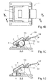
- FIG. 1a-g is a first embodiment of the invention shown.
- FIG 1 a is shown an isometric view of a phone holder 1.
- the phone holder 1 comprises a rear support structure 2, intended to face a backside of a phone 8 (see figure 1 g) , and a front support structure 3, intended to face a front side of a phone 8.
- the phone holder 1 further comprises a right side support structure 4 and a left side support structure 5 in order to align a phone in the phone holder 1.
- the support structures 2, 3, 4, 5 defines a slot opening 6 through which a phone 8 may be inserted.
- the phone holder 1 is provided with a lower stop structure 12.
- the stop structure may be provided with connectors 11 for connecting a phone 8 to be charged or connected to a vehicle electronic system.
- the phone holder 1 needs to be attached to the interior of a vehicle and may either be attached by a separate attachment structure or an integrated attachment portion 13 which is specifically designed for attaching the phone holder 1 to a vehicle.
- the phone holder 1 is further provided with a rotatable member 7 which in this case is exemplified as a roll or wide wheel located in the centre portion of the rear support structure 2.
- the rotatable member 7 rotates around a centre axle 14 which is resiliently suspended by a spring arrangement 10.
- the rotatable member 7 is in contact with a latch 9 (see figure 1c and an enlargement in figure 1 f) designed to allow the rotatable member to rotate in the insertion direction, ID, while preventing the rotatable member from being able to rotate in a release direction, RD.
- the latch 9 is designed to allow insertion of a phone 8 in the insertion direction ID while preventing a phone 8 from being moved in the release direction RD when the rotatable member 7 is in contact with a phone 8 in the phone holder 1.
- the function of the latch may be best seen in figure 1f where it may be seen that the latch 9 is pressed against the surface of the rotatable member 7 by means of a spring 15.
- the geometrical configuration of the latch 9 is designed such that when the rotatable member is influenced by a turning force in the release direction RD will the surface friction between the latch 9 and the rotatable member 7 cause the arrangement to be stuck and prevent rotation of the rotatable member 7.
- the rotatable member 7 is turned in the other direction, i.e. the insertion direction ID, will the geometrical configuration of the latch 9 allow the rotatable member to rotate.
- the phone holder is also provided with a control mechanism 100 which is used to switch the phone holder 1 from being in a first insertion mode (I) and a second, release mode (II).
- the control mechanism 100 which in this case comprises a resilient flap 101, is designed to, when being pressed upon its free end 102 upwards in the release direction R (see fig 1c-e ), change the phone holder from being in a first insertion mode (I) to a second, release mode (II).
- the change from the first mode to the second mode is caused by the flap 101 performing a pivotal motion by engaging with an anvil 104 such that the remote end portion 103 will cause a casing 105, to which the axle 14 of the rotatable member 7 is attached, to move away from the rear support structure 2.
- the change of modes is thus caused by moving the rotatable member 7 relative the rear support structure.
- insertion mode (I) is the rotatable member located in a position in which a phone 8 inserted in the phone holder 1 is in contact with the rotatable member 7 when the control mechanism 100 and its flap 101 are at rest. This first insertion mode (I) is exemplified in figure 1 d.
- this mode may thus a phone 8 only be moved in the insertion direction ID when located in the phone holder 1. If the phone 8 is tried to be moved in the release direction RD will the latch 9 prevent the rotatable member 7 from rotating and thus causing the phone 8 not to moved.
- the flap 101 is being pressed upon will the rotatable member 7 change its position to a position in which a phone 8 inserted in the phone holder 1 not is in contact with the rotatable member 7 and the mode is changed by the control mechanism 100.
- This configuration thus corresponds to the second release mode (II) in which a phone 8 inserted in the phone holder 1 may be moved in the release direction RD since the retaining force from the rotatable member 7 no longer is working on the phone 8.
- This second release mode (II) is illustrated in figure 1e in which the control mechanism 100 has been pressed upwards such that the surface of the rotatable member 7 is lowered below the surface level of the rear support structure 2 facing towards the space where a phone 8 is intended to be located.
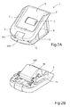
- FIG. 2a is an isometric view shown of a phone holder 1 having the same kind of support structures 2,3,4,5 defining a slot 6, a lower stop structure 12, an attachment portion 13 and a rotatable member 7 as described for the device of figure 1 .
- the second embodiment differs in that there is a different control mechanism 200, comprising a push button 201, in the lower support structure 12 to be used to switch the phone holder from the first, insertion mode (I) to the second, release mode(II).
- FIG 2b is shown the backside of the rear support structure 2 which is provided with a casing 205 comprising the rotatable member 7 (see figure 2a ) which is attached to a centre axle 14 resiliently pressed towards the rear support structure 2 by a spring arrangement 10.
- a cross sectional view along line A ---A in figure 2c disclosing a view from above of the phone holder, is disclosed in figure 2d .
- the phone holder 1 shown when it is in its first, insertion mode (I).
- I In this cross sectional view is it shown how the rotatable member 7 is placed next to and in contact with a latch 9 being pressed against the rotatable member by a spring 15 in an arrangement corresponding to the one described for the first embodiment.
- the principle for switching between the first, insertion mode (I) and the second, release mode (II) is based on controlling the latch 9 instead of moving the relative position of the rear support plate 2 and the rotatable member 7 as for the first embodiment disclosed in figure 1 .
- the push button 201 is connected to an actuator protrusion 202 located on a shank (or pair of shanks) 203.
- the actuator protrusion 203 is designed to be able to engage with a latch protrusion 204.
- the latch may be substituted for other arrangements function to prevent the rotatable member from rotating freely in a desired direction and thus also other arrangements of the release mechanism may be used.
- the arrangements of the support structures may be designed otherwise, e.g. may it be sufficient with a single side support structure to be used for aligning the phone instead of using both a left and right side support structure enabling different sizes of the width of a phone to be used in the same phone holder.
Priority Applications (1)
| Application Number | Priority Date | Filing Date | Title |
|---|---|---|---|
| EP15166894.4A EP3090902B1 (de) | 2015-05-08 | 2015-05-08 | Telefonhalter für ein fahrzeug |
Applications Claiming Priority (1)
| Application Number | Priority Date | Filing Date | Title |
|---|---|---|---|
| EP15166894.4A EP3090902B1 (de) | 2015-05-08 | 2015-05-08 | Telefonhalter für ein fahrzeug |
Publications (2)
| Publication Number | Publication Date |
|---|---|
| EP3090902A1 true EP3090902A1 (de) | 2016-11-09 |
| EP3090902B1 EP3090902B1 (de) | 2018-07-11 |
Family
ID=53054956
Family Applications (1)
| Application Number | Title | Priority Date | Filing Date |
|---|---|---|---|
| EP15166894.4A Active EP3090902B1 (de) | 2015-05-08 | 2015-05-08 | Telefonhalter für ein fahrzeug |
Country Status (1)
| Country | Link |
|---|---|
| EP (1) | EP3090902B1 (de) |
Cited By (2)
| Publication number | Priority date | Publication date | Assignee | Title |
|---|---|---|---|---|
| FR3070934A1 (fr) * | 2017-09-11 | 2019-03-15 | Faurecia Interieur Industrie | Station d'accueil pour appareil electronique mobile et habillage interieur de vehicule comprenant une telle station d'accueil |
| CN109866696A (zh) * | 2017-12-01 | 2019-06-11 | 丰田自动车株式会社 | 车载固定结构 |
Citations (5)
| Publication number | Priority date | Publication date | Assignee | Title |
|---|---|---|---|---|
| EP0585011A1 (de) | 1992-08-22 | 1994-03-02 | Nec Corporation | Haltevorrichtung für tragbares Gerät |
| US5996866A (en) | 1998-09-29 | 1999-12-07 | Lear Corporation | Phone holder for vehicle console |
| DE20306910U1 (de) | 2003-05-02 | 2003-08-07 | Tobe Kfz Zubehoer Handel Gmbh | Armkonsole (für Kraftfahrzeuge) mit integrierter Telefon-Freisprech-Anlage |
| US20060145039A1 (en) * | 2004-11-24 | 2006-07-06 | Shawver Michael J | Universal modular docking platform for portable device |
| EP1973313A1 (de) | 2007-03-23 | 2008-09-24 | Henryk Bury Mielec Sp.zo.o. | Fahrzeughalterung für ein Mobiltelefon |
-
2015
- 2015-05-08 EP EP15166894.4A patent/EP3090902B1/de active Active
Patent Citations (5)
| Publication number | Priority date | Publication date | Assignee | Title |
|---|---|---|---|---|
| EP0585011A1 (de) | 1992-08-22 | 1994-03-02 | Nec Corporation | Haltevorrichtung für tragbares Gerät |
| US5996866A (en) | 1998-09-29 | 1999-12-07 | Lear Corporation | Phone holder for vehicle console |
| DE20306910U1 (de) | 2003-05-02 | 2003-08-07 | Tobe Kfz Zubehoer Handel Gmbh | Armkonsole (für Kraftfahrzeuge) mit integrierter Telefon-Freisprech-Anlage |
| US20060145039A1 (en) * | 2004-11-24 | 2006-07-06 | Shawver Michael J | Universal modular docking platform for portable device |
| EP1973313A1 (de) | 2007-03-23 | 2008-09-24 | Henryk Bury Mielec Sp.zo.o. | Fahrzeughalterung für ein Mobiltelefon |
Cited By (2)
| Publication number | Priority date | Publication date | Assignee | Title |
|---|---|---|---|---|
| FR3070934A1 (fr) * | 2017-09-11 | 2019-03-15 | Faurecia Interieur Industrie | Station d'accueil pour appareil electronique mobile et habillage interieur de vehicule comprenant une telle station d'accueil |
| CN109866696A (zh) * | 2017-12-01 | 2019-06-11 | 丰田自动车株式会社 | 车载固定结构 |
Also Published As
| Publication number | Publication date |
|---|---|
| EP3090902B1 (de) | 2018-07-11 |
Similar Documents
| Publication | Publication Date | Title |
|---|---|---|
| US8066330B2 (en) | Motor-vehicle headrest | |
| CN103298648B (zh) | 适于机动车辆座椅的包括两对导轨的纵向调节装置 | |
| JP4500739B2 (ja) | 車両用ペダルの後退防止装置 | |
| KR102575354B1 (ko) | 차량용 콘솔장치 | |
| EP3090902B1 (de) | Telefonhalter für ein fahrzeug | |
| CN102294972B (zh) | 用于车辆的杯子保持设备 | |
| JP2010052489A (ja) | パネル着脱機構 | |
| CN206327154U (zh) | 用于车辆的电子离合器踏板 | |
| EP2752335B1 (de) | Schiebbares Gesprächsspiegel mit magnetsiches Halterung für Fahrzeug | |
| CN105793102A (zh) | 包括能够枢转的扶手和摆式元件的系统 | |
| CN102402972B (zh) | 踏板装置 | |
| EP0640511A2 (de) | Auto-Stereosystem | |
| US9796363B2 (en) | Brake pedal assembly | |
| JP2014234009A (ja) | 車両用装置の取付構造 | |
| EP3048506A1 (de) | Pedal zur fahrzeugbedienung | |
| CN113370906A (zh) | 包括阻挡装置的用于移动电子装置的支撑装置 | |
| JP7068368B2 (ja) | 車両用収納構造 | |
| JP5115228B2 (ja) | パネル着脱機構およびそれを有する車載装置 | |
| CN108312924B (zh) | 用于交通工具扶手的制动器 | |
| JP2008143379A (ja) | トノカバー係合構造 | |
| US9296371B2 (en) | Position adjustable pedal | |
| CN104417510A (zh) | 用于机动车的驻车制动装置 | |
| CN212220010U (zh) | 汽车杯托安装结构 | |
| JP2009113697A (ja) | オーバーヘッドコンソールの仮固定用爪 | |
| KR100840220B1 (ko) | 전자 파킹 브레이크의 스위치 |
Legal Events
| Date | Code | Title | Description |
|---|---|---|---|
| PUAI | Public reference made under article 153(3) epc to a published international application that has entered the european phase |
Free format text: ORIGINAL CODE: 0009012 |
|
| AK | Designated contracting states |
Kind code of ref document: A1 Designated state(s): AL AT BE BG CH CY CZ DE DK EE ES FI FR GB GR HR HU IE IS IT LI LT LU LV MC MK MT NL NO PL PT RO RS SE SI SK SM TR |
|
| AX | Request for extension of the european patent |
Extension state: BA ME |
|
| STAA | Information on the status of an ep patent application or granted ep patent |
Free format text: STATUS: REQUEST FOR EXAMINATION WAS MADE |
|
| 17P | Request for examination filed |
Effective date: 20170509 |
|
| RBV | Designated contracting states (corrected) |
Designated state(s): AL AT BE BG CH CY CZ DE DK EE ES FI FR GB GR HR HU IE IS IT LI LT LU LV MC MK MT NL NO PL PT RO RS SE SI SK SM TR |
|
| GRAP | Despatch of communication of intention to grant a patent |
Free format text: ORIGINAL CODE: EPIDOSNIGR1 |
|
| STAA | Information on the status of an ep patent application or granted ep patent |
Free format text: STATUS: GRANT OF PATENT IS INTENDED |
|
| INTG | Intention to grant announced |
Effective date: 20180108 |
|
| GRAS | Grant fee paid |
Free format text: ORIGINAL CODE: EPIDOSNIGR3 |
|
| GRAA | (expected) grant |
Free format text: ORIGINAL CODE: 0009210 |
|
| STAA | Information on the status of an ep patent application or granted ep patent |
Free format text: STATUS: THE PATENT HAS BEEN GRANTED |
|
| AK | Designated contracting states |
Kind code of ref document: B1 Designated state(s): AL AT BE BG CH CY CZ DE DK EE ES FI FR GB GR HR HU IE IS IT LI LT LU LV MC MK MT NL NO PL PT RO RS SE SI SK SM TR |
|
| REG | Reference to a national code |
Ref country code: GB Ref legal event code: FG4D |
|
| REG | Reference to a national code |
Ref country code: CH Ref legal event code: EP |
|
| REG | Reference to a national code |
Ref country code: AT Ref legal event code: REF Ref document number: 1016533 Country of ref document: AT Kind code of ref document: T Effective date: 20180715 |
|
| REG | Reference to a national code |
Ref country code: IE Ref legal event code: FG4D |
|
| REG | Reference to a national code |
Ref country code: DE Ref legal event code: R096 Ref document number: 602015013254 Country of ref document: DE |
|
| REG | Reference to a national code |
Ref country code: NL Ref legal event code: MP Effective date: 20180711 |
|
| REG | Reference to a national code |
Ref country code: LT Ref legal event code: MG4D |
|
| REG | Reference to a national code |
Ref country code: AT Ref legal event code: MK05 Ref document number: 1016533 Country of ref document: AT Kind code of ref document: T Effective date: 20180711 |
|
| PG25 | Lapsed in a contracting state [announced via postgrant information from national office to epo] |
Ref country code: NL Free format text: LAPSE BECAUSE OF FAILURE TO SUBMIT A TRANSLATION OF THE DESCRIPTION OR TO PAY THE FEE WITHIN THE PRESCRIBED TIME-LIMIT Effective date: 20180711 |
|
| PG25 | Lapsed in a contracting state [announced via postgrant information from national office to epo] |
Ref country code: FI Free format text: LAPSE BECAUSE OF FAILURE TO SUBMIT A TRANSLATION OF THE DESCRIPTION OR TO PAY THE FEE WITHIN THE PRESCRIBED TIME-LIMIT Effective date: 20180711 Ref country code: IS Free format text: LAPSE BECAUSE OF FAILURE TO SUBMIT A TRANSLATION OF THE DESCRIPTION OR TO PAY THE FEE WITHIN THE PRESCRIBED TIME-LIMIT Effective date: 20181111 Ref country code: RS Free format text: LAPSE BECAUSE OF FAILURE TO SUBMIT A TRANSLATION OF THE DESCRIPTION OR TO PAY THE FEE WITHIN THE PRESCRIBED TIME-LIMIT Effective date: 20180711 Ref country code: NO Free format text: LAPSE BECAUSE OF FAILURE TO SUBMIT A TRANSLATION OF THE DESCRIPTION OR TO PAY THE FEE WITHIN THE PRESCRIBED TIME-LIMIT Effective date: 20181011 Ref country code: AT Free format text: LAPSE BECAUSE OF FAILURE TO SUBMIT A TRANSLATION OF THE DESCRIPTION OR TO PAY THE FEE WITHIN THE PRESCRIBED TIME-LIMIT Effective date: 20180711 Ref country code: GR Free format text: LAPSE BECAUSE OF FAILURE TO SUBMIT A TRANSLATION OF THE DESCRIPTION OR TO PAY THE FEE WITHIN THE PRESCRIBED TIME-LIMIT Effective date: 20181012 Ref country code: BG Free format text: LAPSE BECAUSE OF FAILURE TO SUBMIT A TRANSLATION OF THE DESCRIPTION OR TO PAY THE FEE WITHIN THE PRESCRIBED TIME-LIMIT Effective date: 20181011 Ref country code: SE Free format text: LAPSE BECAUSE OF FAILURE TO SUBMIT A TRANSLATION OF THE DESCRIPTION OR TO PAY THE FEE WITHIN THE PRESCRIBED TIME-LIMIT Effective date: 20180711 Ref country code: LT Free format text: LAPSE BECAUSE OF FAILURE TO SUBMIT A TRANSLATION OF THE DESCRIPTION OR TO PAY THE FEE WITHIN THE PRESCRIBED TIME-LIMIT Effective date: 20180711 Ref country code: PL Free format text: LAPSE BECAUSE OF FAILURE TO SUBMIT A TRANSLATION OF THE DESCRIPTION OR TO PAY THE FEE WITHIN THE PRESCRIBED TIME-LIMIT Effective date: 20180711 |
|
| PG25 | Lapsed in a contracting state [announced via postgrant information from national office to epo] |
Ref country code: HR Free format text: LAPSE BECAUSE OF FAILURE TO SUBMIT A TRANSLATION OF THE DESCRIPTION OR TO PAY THE FEE WITHIN THE PRESCRIBED TIME-LIMIT Effective date: 20180711 Ref country code: AL Free format text: LAPSE BECAUSE OF FAILURE TO SUBMIT A TRANSLATION OF THE DESCRIPTION OR TO PAY THE FEE WITHIN THE PRESCRIBED TIME-LIMIT Effective date: 20180711 Ref country code: LV Free format text: LAPSE BECAUSE OF FAILURE TO SUBMIT A TRANSLATION OF THE DESCRIPTION OR TO PAY THE FEE WITHIN THE PRESCRIBED TIME-LIMIT Effective date: 20180711 |
|
| REG | Reference to a national code |
Ref country code: DE Ref legal event code: R097 Ref document number: 602015013254 Country of ref document: DE |
|
| PG25 | Lapsed in a contracting state [announced via postgrant information from national office to epo] |
Ref country code: ES Free format text: LAPSE BECAUSE OF FAILURE TO SUBMIT A TRANSLATION OF THE DESCRIPTION OR TO PAY THE FEE WITHIN THE PRESCRIBED TIME-LIMIT Effective date: 20180711 Ref country code: CZ Free format text: LAPSE BECAUSE OF FAILURE TO SUBMIT A TRANSLATION OF THE DESCRIPTION OR TO PAY THE FEE WITHIN THE PRESCRIBED TIME-LIMIT Effective date: 20180711 Ref country code: EE Free format text: LAPSE BECAUSE OF FAILURE TO SUBMIT A TRANSLATION OF THE DESCRIPTION OR TO PAY THE FEE WITHIN THE PRESCRIBED TIME-LIMIT Effective date: 20180711 Ref country code: RO Free format text: LAPSE BECAUSE OF FAILURE TO SUBMIT A TRANSLATION OF THE DESCRIPTION OR TO PAY THE FEE WITHIN THE PRESCRIBED TIME-LIMIT Effective date: 20180711 |
|
| PLBE | No opposition filed within time limit |
Free format text: ORIGINAL CODE: 0009261 |
|
| STAA | Information on the status of an ep patent application or granted ep patent |
Free format text: STATUS: NO OPPOSITION FILED WITHIN TIME LIMIT |
|
| PG25 | Lapsed in a contracting state [announced via postgrant information from national office to epo] |
Ref country code: DK Free format text: LAPSE BECAUSE OF FAILURE TO SUBMIT A TRANSLATION OF THE DESCRIPTION OR TO PAY THE FEE WITHIN THE PRESCRIBED TIME-LIMIT Effective date: 20180711 Ref country code: SM Free format text: LAPSE BECAUSE OF FAILURE TO SUBMIT A TRANSLATION OF THE DESCRIPTION OR TO PAY THE FEE WITHIN THE PRESCRIBED TIME-LIMIT Effective date: 20180711 Ref country code: SK Free format text: LAPSE BECAUSE OF FAILURE TO SUBMIT A TRANSLATION OF THE DESCRIPTION OR TO PAY THE FEE WITHIN THE PRESCRIBED TIME-LIMIT Effective date: 20180711 |
|
| 26N | No opposition filed |
Effective date: 20190412 |
|
| PG25 | Lapsed in a contracting state [announced via postgrant information from national office to epo] |
Ref country code: SI Free format text: LAPSE BECAUSE OF FAILURE TO SUBMIT A TRANSLATION OF THE DESCRIPTION OR TO PAY THE FEE WITHIN THE PRESCRIBED TIME-LIMIT Effective date: 20180711 |
|
| REG | Reference to a national code |
Ref country code: CH Ref legal event code: PL |
|
| GBPC | Gb: european patent ceased through non-payment of renewal fee |
Effective date: 20190508 |
|
| PG25 | Lapsed in a contracting state [announced via postgrant information from national office to epo] |
Ref country code: MC Free format text: LAPSE BECAUSE OF FAILURE TO SUBMIT A TRANSLATION OF THE DESCRIPTION OR TO PAY THE FEE WITHIN THE PRESCRIBED TIME-LIMIT Effective date: 20180711 Ref country code: CH Free format text: LAPSE BECAUSE OF NON-PAYMENT OF DUE FEES Effective date: 20190531 Ref country code: LI Free format text: LAPSE BECAUSE OF NON-PAYMENT OF DUE FEES Effective date: 20190531 |
|
| REG | Reference to a national code |
Ref country code: BE Ref legal event code: MM Effective date: 20190531 |
|
| PG25 | Lapsed in a contracting state [announced via postgrant information from national office to epo] |
Ref country code: LU Free format text: LAPSE BECAUSE OF NON-PAYMENT OF DUE FEES Effective date: 20190508 |
|
| PG25 | Lapsed in a contracting state [announced via postgrant information from national office to epo] |
Ref country code: TR Free format text: LAPSE BECAUSE OF FAILURE TO SUBMIT A TRANSLATION OF THE DESCRIPTION OR TO PAY THE FEE WITHIN THE PRESCRIBED TIME-LIMIT Effective date: 20180711 |
|
| PG25 | Lapsed in a contracting state [announced via postgrant information from national office to epo] |
Ref country code: GB Free format text: LAPSE BECAUSE OF NON-PAYMENT OF DUE FEES Effective date: 20190508 Ref country code: IE Free format text: LAPSE BECAUSE OF NON-PAYMENT OF DUE FEES Effective date: 20190508 |
|
| PG25 | Lapsed in a contracting state [announced via postgrant information from national office to epo] |
Ref country code: BE Free format text: LAPSE BECAUSE OF NON-PAYMENT OF DUE FEES Effective date: 20190531 |
|
| PG25 | Lapsed in a contracting state [announced via postgrant information from national office to epo] |
Ref country code: PT Free format text: LAPSE BECAUSE OF FAILURE TO SUBMIT A TRANSLATION OF THE DESCRIPTION OR TO PAY THE FEE WITHIN THE PRESCRIBED TIME-LIMIT Effective date: 20181111 |
|
| PG25 | Lapsed in a contracting state [announced via postgrant information from national office to epo] |
Ref country code: CY Free format text: LAPSE BECAUSE OF FAILURE TO SUBMIT A TRANSLATION OF THE DESCRIPTION OR TO PAY THE FEE WITHIN THE PRESCRIBED TIME-LIMIT Effective date: 20180711 |
|
| PG25 | Lapsed in a contracting state [announced via postgrant information from national office to epo] |
Ref country code: MT Free format text: LAPSE BECAUSE OF FAILURE TO SUBMIT A TRANSLATION OF THE DESCRIPTION OR TO PAY THE FEE WITHIN THE PRESCRIBED TIME-LIMIT Effective date: 20180711 Ref country code: HU Free format text: LAPSE BECAUSE OF FAILURE TO SUBMIT A TRANSLATION OF THE DESCRIPTION OR TO PAY THE FEE WITHIN THE PRESCRIBED TIME-LIMIT; INVALID AB INITIO Effective date: 20150508 |
|
| PG25 | Lapsed in a contracting state [announced via postgrant information from national office to epo] |
Ref country code: MK Free format text: LAPSE BECAUSE OF FAILURE TO SUBMIT A TRANSLATION OF THE DESCRIPTION OR TO PAY THE FEE WITHIN THE PRESCRIBED TIME-LIMIT Effective date: 20180711 |
|
| PGFP | Annual fee paid to national office [announced via postgrant information from national office to epo] |
Ref country code: IT Payment date: 20230420 Year of fee payment: 9 Ref country code: FR Payment date: 20230420 Year of fee payment: 9 Ref country code: DE Payment date: 20230419 Year of fee payment: 9 |
|
| P01 | Opt-out of the competence of the unified patent court (upc) registered |
Effective date: 20231212 |