EP3090887A1 - A towing hitch assembly and a towing system - Google Patents
A towing hitch assembly and a towing system Download PDFInfo
- Publication number
- EP3090887A1 EP3090887A1 EP15166796.1A EP15166796A EP3090887A1 EP 3090887 A1 EP3090887 A1 EP 3090887A1 EP 15166796 A EP15166796 A EP 15166796A EP 3090887 A1 EP3090887 A1 EP 3090887A1
- Authority
- EP
- European Patent Office
- Prior art keywords
- towing
- vehicle
- hitch assembly
- carrier vehicle
- recess
- Prior art date
- Legal status (The legal status is an assumption and is not a legal conclusion. Google has not performed a legal analysis and makes no representation as to the accuracy of the status listed.)
- Granted
Links
- 230000005484 gravity Effects 0.000 claims description 7
- 230000008901 benefit Effects 0.000 description 19
- 239000000463 material Substances 0.000 description 4
- 230000032258 transport Effects 0.000 description 4
- 239000000284 extract Substances 0.000 description 3
- 230000003993 interaction Effects 0.000 description 3
- 238000004519 manufacturing process Methods 0.000 description 3
- 230000007246 mechanism Effects 0.000 description 3
- 238000010276 construction Methods 0.000 description 2
- 230000002349 favourable effect Effects 0.000 description 2
- 230000004048 modification Effects 0.000 description 2
- 238000012986 modification Methods 0.000 description 2
- 230000000284 resting effect Effects 0.000 description 2
- 230000008859 change Effects 0.000 description 1
- 230000007797 corrosion Effects 0.000 description 1
- 238000005260 corrosion Methods 0.000 description 1
- 239000000314 lubricant Substances 0.000 description 1
- 230000010355 oscillation Effects 0.000 description 1
- 230000007306 turnover Effects 0.000 description 1
- 239000002699 waste material Substances 0.000 description 1
- XLYOFNOQVPJJNP-UHFFFAOYSA-N water Substances O XLYOFNOQVPJJNP-UHFFFAOYSA-N 0.000 description 1
Images


Classifications
-
- B—PERFORMING OPERATIONS; TRANSPORTING
- B60—VEHICLES IN GENERAL
- B60D—VEHICLE CONNECTIONS
- B60D1/00—Traction couplings; Hitches; Draw-gear; Towing devices
- B60D1/01—Traction couplings or hitches characterised by their type
-
- B—PERFORMING OPERATIONS; TRANSPORTING
- B60—VEHICLES IN GENERAL
- B60D—VEHICLE CONNECTIONS
- B60D1/00—Traction couplings; Hitches; Draw-gear; Towing devices
- B60D1/14—Draw-gear or towing devices characterised by their type
- B60D1/143—Draw-gear or towing devices characterised by their type characterised by the mounting of the draw-gear on the towed vehicle
-
- B—PERFORMING OPERATIONS; TRANSPORTING
- B60—VEHICLES IN GENERAL
- B60D—VEHICLE CONNECTIONS
- B60D1/00—Traction couplings; Hitches; Draw-gear; Towing devices
- B60D1/14—Draw-gear or towing devices characterised by their type
- B60D1/145—Draw-gear or towing devices characterised by their type consisting of an elongated single bar or tube
- B60D1/155—Draw-gear or towing devices characterised by their type consisting of an elongated single bar or tube comprising telescopic or foldable parts
-
- B—PERFORMING OPERATIONS; TRANSPORTING
- B60—VEHICLES IN GENERAL
- B60D—VEHICLE CONNECTIONS
- B60D1/00—Traction couplings; Hitches; Draw-gear; Towing devices
- B60D1/24—Traction couplings; Hitches; Draw-gear; Towing devices characterised by arrangements for particular functions
-
- B—PERFORMING OPERATIONS; TRANSPORTING
- B60—VEHICLES IN GENERAL
- B60D—VEHICLE CONNECTIONS
- B60D1/00—Traction couplings; Hitches; Draw-gear; Towing devices
- B60D1/24—Traction couplings; Hitches; Draw-gear; Towing devices characterised by arrangements for particular functions
- B60D1/36—Traction couplings; Hitches; Draw-gear; Towing devices characterised by arrangements for particular functions for facilitating connection, e.g. hitch catchers, visual guide means, signalling aids
-
- B—PERFORMING OPERATIONS; TRANSPORTING
- B60—VEHICLES IN GENERAL
- B60D—VEHICLE CONNECTIONS
- B60D1/00—Traction couplings; Hitches; Draw-gear; Towing devices
- B60D1/48—Traction couplings; Hitches; Draw-gear; Towing devices characterised by the mounting
- B60D1/54—Traction couplings; Hitches; Draw-gear; Towing devices characterised by the mounting collapsible or retractable when not in use, e.g. hide-away hitches
-
- B—PERFORMING OPERATIONS; TRANSPORTING
- B60—VEHICLES IN GENERAL
- B60D—VEHICLE CONNECTIONS
- B60D1/00—Traction couplings; Hitches; Draw-gear; Towing devices
- B60D2001/001—Traction couplings; Hitches; Draw-gear; Towing devices specially adapted for use on vehicles other than cars
- B60D2001/005—Traction couplings; Hitches; Draw-gear; Towing devices specially adapted for use on vehicles other than cars for carts, scooters, or the like
Definitions
- the present invention relates to a towing hitch assembly according to the preamble of claim 1 and a towing system according to claim 9.
- the transports can for example be of elements to be assembled at an assembly line or it could be waste products to be disposed of in another part of the facility.
- the aim of using auto guided vehicles is to increase efficiency and to reduce man hours for simple tasks.
- the auto guided vehicles can either carry the transported goods by themselves or use another vehicle for carrying the goods. In the latter case some sort of wagon is often used.
- a towing hitch assembly comprising a first part that is connectable to a carrier vehicle and a second part which is attachable to a towing vehicle, the second part being slidably moveable relative to the first part, between a first retracted configuration, and a second extended configuration, characterized in that when the first part is attached to a carrier vehicle, a towing vehicle can by engaging a connecting section of the second part, pull the second part to the second extended configuration, wherein the second extended configuration allows for towing the carrier vehicle, and wherein when a towing vehicle disengages the connecting section, the second part will attend the first retracted configuration automatically, by means of an installed retraction device acting to slidably retract the first part.
- the above towing hitch assembly has the advantage that the carrier vehicle to which the assembly is to be attached can be stored very conveniently. Another advantage is that the towing hitch assembly can be connected and disconnected automatically, without interaction by any human hand. A further advantage is that the manoeuvrability of a connected towing vehicle is adaptable, without affecting the ability to stow the carrier vehicle.
- the retracted second part is kept in the first retracted configuration by means of the retraction device.
- the advantage of this aspect is that the towing hitch assembly will not unexpectedly move from retracted configuration to extended configuration. Further the advantage is that there is no need for a specific device to keep the towing hitch assembly in position after usage.
- the retraction device comprises a helical spring and/or a gas spring.
- the connecting section comprises a recess.
- a protrusion is simple to implement for a towing vehicle that can connect to the recess.
- the recess has a triangular shape, preferably the recess has a corner of said triangular shape positioned in the main towing direction of a carrier vehicle, such that when connecting to the recess, guiding may be achieved by the angled sides of the triangular shape.
- the advantage of this is that it saves material on the towing hitch, but still provides a large base line where a protrusion of a towing vehicle can access the recess. For comparison a round hole would have to remove considerably more material in order to provide for a comparable base line width.
- the guiding is provided in a particularly simple manner.
- a locking device is provided on the second part.
- the advantage of providing a locking device on the second part is so to prevent the second from retracting during towing. Instead the second part stays in extended configuration until the towing vehicle is disconnected. This has the further advantage that free movement of the towing vehicle is guaranteed.
- the locking device uses a side of a towing vehicle to be kept in locking position, wherein the side is preferably an upper side of a towing vehicle.
- the advantage of using a side of the towing vehicle for keeping the locking device in a locked position is that the locking is particularly simple and there is no need for modification of the towing vehicle.
- the locking device uses gravity to reach the correct positon for being able to engage a towing vehicle, preferably the correct position is reached by using a transversal axis that does not run through the centre of gravity of the locking device.
- This configuration of the locking device is particularly advantageous, as no other springs or other devices are needed. Thus it is both reliable and cost effective, and uncomplicated.
- a towing system comprising a towing vehicle, a carrier vehicle, and a towing hitch assembly according to any of the aspects above attached to the carrier vehicle.
- the towing system is particularly advantageous for transports within a production facility.
- the carrier vehicle comprises two swivelling wheels, preferably four swivelling wheels.
- the manoeuvrability of the towing system is considerably increased. It further gives the advantage that if a human desires to move the back end of the carrier vehicle sideways, this can be easily achieved without applying considerably force. If four swivelling wheels are applied, both ends of the carrier vehicle can be moved more freely. If no further wheels in addition to the four swivelling wheels are applied, the carrier vehicle can be moved with ease in any direction.
- the carrier vehicle has a limited travel speed of 15 km/h, preferably 7 km/h, even more preferred 3 km/h, and/or the carrier vehicle has a maximum total weight of 400 kg, preferably 200 kg.
- the vehicle By applying a limited travel speed, the vehicle does not risk to damage any persons when moving. It is also an advantage that the carrier vehicle can be designed in a particularly simple manner, thus being very cost effective but also lightweight.
- the advantage of providing a maximum total weight of 400 kg, or even 200 kg, is that the basic design can be kept simple. It can be made up by a simple frame work construction.
- the towing system is adapted for indoor use only.
- the advantage of this aspect is that the towing vehicle, the towing hitch assembly and the carrier vehicle can be made from simple materials that need not be able to manage rain, wind etc. It is a further advantage that the support surface on which the system is to operate is in general flat and without irregularities found outdoors. Thus both the weight and cost of the system can be reduced. Electronics of the towing vehicle need not be water proof. The materials used need not be corrosion resistant and do not need to be stable when exposed to ultraviolet light.
- the towing vehicle has a high point that engages the connecting section of the towing hitch assembly, such that the towing vehicle in full can pass under the towing hitch assembly for engaging the connecting section.
- the towing vehicle is an auto guided vehicle, preferably being an electric vehicle.
- the width of the towing vehicle is smaller than the width of the carrier vehicle.
- the towing hitch assembly has a second part 3 that is slidably engaged in a first part 2.
- the second part 3 further has a front end 10 and a back end 11.
- the back end 11 can be connected to a retraction device 5, as seen in Figure 7 .
- the connection between the back end 11 and the retraction device 5 can be made by means of an opening 12 in the back end 11.
- the function of the towing hitch assembly 1 is the following. It is attached to a carrier vehicle 15 underside. A towing vehicle 20 passes under the carrier vehicle 15 and engages a connection section 4 of the first part 2; see for example Figures 7 and 9 . As the towing vehicle 20 passes under the carrier vehicle 15, the second part is drawn from a retracted position A to an extended configuration B, as seen in Figure 3 and 4 .
- First part 2 is attachable to a carrier vehicle 15, see figure 3 and 4 .
- the first part 2 can be made from two essentially parallel tubes.
- a lubricant such that the second part 3 can slide with ease inside the first part 2.
- ball bushings 47 it is possible to provide the first part 2 with ball bushings 47, as can be seen in Figure 11a and 11b with two ball bushings 47 at a distance from each other in each tube the friction is considerably lower and the guiding of the second part 3 inside the first part 2 is much improved.
- the tube configuration is not mandatory, the first part 2 can be made up from for example squared bars, with a hole.
- the first part 2 can also be made from a rail and wheel assembly.
- the second part 3 is best seen in Figure 1 and Figure 2 .
- the second part 3 comprises a connecting front end 10, a connecting section 4, a locking device 9, and a back end 11.
- the second part 3 comprises preferably two longitudinal tubes 14 that can slide inside the first part 2.
- the tubes 14 are shown to have a circular shape, this is to be understood to not be a mandatory shape.
- the tubes 14 of the second part 3 could also have a square section, as long as the first part 2 is adapted for good sliding ability.
- the tubes 14 of the second part 3 need not be completely straight, even though this is preferred for the best sliding ability.
- the front end 10 of the first part has a rounded shape. This shape allows for the second part 3 to slide forward in the first part 2 without hooking into a carrier vehicle 15 during extension.
- the front end 10 is preferably provided at an angle to the main length of the second part 3. The angle ensures that when disconnecting from a towing vehicle 20, the second part 3 cannot hook into protrusions as it slides back.
- the angle also provides for a towing vehicle 20 that is in the operation to connect to the connecting section 4 by performing moving rearwards towards the towing hitch assembly 1.
- the towing vehicle 20 has a resilient connecting device 22, the angle helps to push the connecting device 22 downwards such that it can connect to the connecting section 4.
- the rear end 11 is angled in the same manner as the front end 10.
- the towing vehicle 20 has a resilient connecting device 22, the angle helps to push the connecting device 22 downwards such that it can connect to the connecting section 4, when the towing vehicle 20 enters from the rear end 11.
- the back end is also provided with a recess 12 for attachment of a retraction device that will be described below.
- the recess 12 is of course easiest made as a through hole. But it is of course possible to provide an attached hook or an angled edge or any other way of attachment.
- the locking device 9 is provided in a groove in the middle of a central section 40 of the first part.
- the locking device 9 is preferably made as an irregularly shaped element, as seen in Figure 5 and 6 .
- a through hole 41 is provided. By applying the through hole 41 such that it does not run through the centre of gravity 42 of the locking device 9, the locking device is arranged to swing into a resting position. When a towing vehicle passes by the locking device, it is swung up and remains resting on an upper side 21 of a towing vehicle 20. By this position the locking device, together with a not disclosed rim, prevents the second part 3 from sliding back under the carrier vehicle 15.
- Other locking systems are of course thinkable.
- the presented locking device 9 is particularly simple and allows for the important function to allow for automatic retraction of the second part 3 after usage.
- the locking device 9 locks to the upper side 21 of a towing vehicle 20.
- the towing vehicle 20 moves into position according to the arrow 45.
- the locking device 9 is rotated clockwise past a rim 44 on the carrying vehicle 15, in direction of arrow 9a.
- the locking device 9 is in locked position against the upper side 21 of a towing vehicle 20. If the carrying vehicle seeks to approach the towing vehicle it will be prevented to do this by the locking device 9 as the locking device 9 will be pushed against both the rim 44 and the upper side 21.
- the connecting section 4 is preferably made up of a recess 6, see Figure 1 and 2 .
- the recess 6 is positioned closer to the front end 10 than the back end 11 of the second part 3.
- the recess 6 is in general of triangular shape.
- the triangular shape is advantageously positioned such that one corner 7 of the triangular shape is in line with the front end 10, see Figure 2 . This means that the corner 7 is positioned such that at towing in a straight line, the corner will be in contact with connecting device 22 of a towing vehicle 20, see Figure 9 .
- the recess 6 with a triangular shape can guide the connecting device 22. This is possible as the connecting device will hook up from the base line of the recess 6.
- the connecting device 22 will pass the carrier vehicle from back to front and thus also along the recess from the base line 42 to the corner 7.
- the sides of the triangular shape will thus guide the connecting device 22 such that it easily can engage the corner 7.
- the connecting section 4 further is advantageously provided with a cover plate 13.
- the cover plate 13 guides the connecting device 22 before it has reached the corner 7.
- the cover plate 13 prevents the connecting device 22 from extending through the recess 6.
- the cover plate 13 is mainly guiding the connecting device 22 to the corner 7 where it can protrude upwards freely and be supported by the rim 43 in longitudinal direction.
- the cover plate 13 preferably has a rounded edge 43 which keeps an engaged towing vehicle 20 in position within a smaller recess that comprises the corner 7 and the rounded edge 43. This provides for a better operation when towing the carrier vehicle 15.
- the retraction device 5 can be seen in Figure 7 and 9 .
- the retraction device 5 is preferably a helical spring. It should be attached to the second part 3 of the towing hitch assembly 1, and to the carrier vehicle 15 frame.
- the retraction device 5 could also be made from a gas spring 5a or a combination of a gas spring or a helical spring. Other designs are also thinkable of course. It is possible to apply an electrical drive mechanism that retracts the second part 3. It is also possible to apply the towing hitch assembly at an angle and to let gravitation perform the retraction movement. That is the towing hitch assembly 1 is provided with the second part 3 higher than the first part 2 and all at an angle.
- the operation of the retraction device 5 is to apply a retraction force, to retract the first part from an extended configuration A to the retracted configuration B. It is also an aim to keep the second part 3 in the retracted configuration. By having this way of keeping the second part 3 in retracted position, this provides for possibility to extract the second part 3 without having to unlock any extra locks etc.
- a towing system comprising a towing hitch assembly 1 as described above, a carrier vehicle 15 and a towing vehicle 20.
- the carrier vehicle 15 is preferably built from a structure of tubes.
- the carrier vehicle is preferably adapted for indoor use. Thus it can be made in a very simple manner.
- the limited travel speed for the carrier vehicle is preferably 15 km/h, more preferably 10 km/h or more preferable 7 km/h, in particular 3 km/h.
- the low speed limit provides for that the carrier vehicle can have a very simple configuration.
- the carrier vehicle 15 preferably comprises at least two swivelling wheels 16, see Figure 7 . There can be more swivelling wheels 16 if desired. And of course there can be more than four wheels. For example there can be a configuration with two swivelling wheels at the front and back of the carrier vehicle and two wheels around the middle in longitudinal direction.
- the middle wheels are linear wheels with no swivelling function.
- a preferred configuration is two swivelling wheels 16 at the end where the towing hitch assembly can protrude and two linear wheels 16a at the other end, as seen in Figure 7 .
- the maximal total weight of the carrier vehicle 15 is preferred to be 400 kg or preferably below 200 kg.
- the advantage of providing a maximum total weight of 400 kg, or even 200 kg, is that the basic design can be kept simple. It can be made up by a simple frame work construction.
- the towing vehicle 20 is preferably an electrical vehicle.
- the power to the towing vehicle 20 is preferably provided from an internal battery that is rechargeable.
- the important design of the towing vehicle is that it is lower than the height over ground where the towing hitch assembly 1 is attached to the carrier vehicle 15.
- a mayor aspect of the present disclosure is that at operation, the towing vehicle 20 passes in full under the carrier vehicle and engages the connecting section 4 of the second part 3 of the towing hitch assembly. And the towing vehicle 20 then continues its movement in the direction of the towing hitch assembly 1 and extracts the first part, such that the towing hitch assembly 1 attains the extracted configuration as seen in Figure 4 .
- the engagement of the towing vehicle 20 is preferably made by the connecting device 22, i.e. the high point 22 of the towing vehicle 20.
- the high point/connecting device 22 is preferably a pin 22.
- the pin 22 can have a spring resilient function such that when it is pressed down from above it moves resiliently downwards. This provides for an easy engagement of the connecting section 4 as the pin can be partly pressed down by first the rear end 11 of the first part and then be more pressed down by the middle part 40 as the towing vehicle 20 moves under the towing hitch assembly 1.
- the pin 22 can resiliently extend upwards and thereby engage the recess 6 and finally after guiding of the sides 8 reach the corner 7 of the recess 6. If the recess 6 is not triangular, it will with less efficiency reach the end of the recess 6.
- the towing vehicle 20 can move the first part to its extracted configuration B and in doing that also extract the retraction device 5.
- the towing vehicle 20 is preferably an AGV or an auto guided vehicle, this means that it can operate on its own without direct human control. This means that it can be programmed to perform tasks and then perform them without any human intervention. Even if it is not preferred the towing vehicle 20 could be programmed to extract the towing hitch assembly 1 from the first configuration A to the second configuration B, by applying a rear ward movement in front of the carrier vehicle 15, and then engage the recess 6 of the towing hitch assembly 1. And after this a change of direction of the AGV would extract the second part 3.
- the towing vehicle When releasing the first part, the towing vehicle preferably lowers the high point 22. This is performed by a non-disclosed mechanism within the towing vehicle 20. After this is performed the towing vehicle 20 can move freely and the retraction device 5 retracts the first part and the towing hitch assembly attains its retracted position.
Landscapes
- Engineering & Computer Science (AREA)
- Transportation (AREA)
- Mechanical Engineering (AREA)
- Handcart (AREA)
- Agricultural Machines (AREA)
Abstract
Description
- The present invention relates to a towing hitch assembly according to the preamble of
claim 1 and a towing system according toclaim 9. - In industrial manufacturing facilities it has been more and more common to use auto guided vehicles for transports within the industrial manufacturing facility. The transports can for example be of elements to be assembled at an assembly line or it could be waste products to be disposed of in another part of the facility. The aim of using auto guided vehicles is to increase efficiency and to reduce man hours for simple tasks. The auto guided vehicles can either carry the transported goods by themselves or use another vehicle for carrying the goods. In the latter case some sort of wagon is often used.
- When an auto guided vehicle is used in a towing situation there is a further need to reduce man hours by avoiding human interaction for connection and disconnection of a carrier vehicle from a towing vehicle. In general this can be achieved by having a mechanism on the towing vehicle that disengages a connecting recess on a carrier vehicle. However it has been found that the manoeuvring of the combined system of a towing vehicle and a carrier vehicle can be limited. It has been a challenge to arrive at a solution to this without affecting the possibility to store the carrier vehicle when not in use.
- A solution to at least one of the problems discussed above is provided by a towing hitch assembly, wherein the towing hitch assembly comprises a first part that is connectable to a carrier vehicle and a second part which is attachable to a towing vehicle, the second part being slidably moveable relative to the first part, between a first retracted configuration, and a second extended configuration, characterized in that when the first part is attached to a carrier vehicle, a towing vehicle can by engaging a connecting section of the second part, pull the second part to the second extended configuration, wherein the second extended configuration allows for towing the carrier vehicle, and wherein when a towing vehicle disengages the connecting section, the second part will attend the first retracted configuration automatically, by means of an installed retraction device acting to slidably retract the first part.
- The above towing hitch assembly has the advantage that the carrier vehicle to which the assembly is to be attached can be stored very conveniently. Another advantage is that the towing hitch assembly can be connected and disconnected automatically, without interaction by any human hand. A further advantage is that the manoeuvrability of a connected towing vehicle is adaptable, without affecting the ability to stow the carrier vehicle.
- According to another aspect of the present invention the retracted second part is kept in the first retracted configuration by means of the retraction device.
- The advantage of this aspect is that the towing hitch assembly will not unexpectedly move from retracted configuration to extended configuration. Further the advantage is that there is no need for a specific device to keep the towing hitch assembly in position after usage.
- According to a further aspect of the retraction device, it comprises a helical spring and/or a gas spring.
- This has the advantage that it is cost effective and simple to implement. Another advantage is that it can be acquired of the shelf and need no particular modification for implementation.
- According to a further aspect of the connecting section, it comprises a recess.
- The advantage of this is that it is particularly easy to connect to the connecting section. A protrusion is simple to implement for a towing vehicle that can connect to the recess.
- According to a further aspect, the recess has a triangular shape, preferably the recess has a corner of said triangular shape positioned in the main towing direction of a carrier vehicle, such that when connecting to the recess, guiding may be achieved by the angled sides of the triangular shape.
- The advantage of this is that it saves material on the towing hitch, but still provides a large base line where a protrusion of a towing vehicle can access the recess. For comparison a round hole would have to remove considerably more material in order to provide for a comparable base line width. By providing the triangular shape positioned as described, the guiding is provided in a particularly simple manner.
- According to a further aspect of the towing hitch assembly a locking device is provided on the second part.
- The advantage of providing a locking device on the second part is so to prevent the second from retracting during towing. Instead the second part stays in extended configuration until the towing vehicle is disconnected. This has the further advantage that free movement of the towing vehicle is guaranteed.
- According to a further aspect of the locking device, it uses a side of a towing vehicle to be kept in locking position, wherein the side is preferably an upper side of a towing vehicle.
- The advantage of using a side of the towing vehicle for keeping the locking device in a locked position is that the locking is particularly simple and there is no need for modification of the towing vehicle. By using the upper side for locking, it provides for using gravity as a means of keeping the locking device in locked position.
- According to a further aspect of the locking device it uses gravity to reach the correct positon for being able to engage a towing vehicle, preferably the correct position is reached by using a transversal axis that does not run through the centre of gravity of the locking device.
- This configuration of the locking device is particularly advantageous, as no other springs or other devices are needed. Thus it is both reliable and cost effective, and uncomplicated.
- According to a further aspect of the invention there is provided a towing system comprising a towing vehicle, a carrier vehicle, and a towing hitch assembly according to any of the aspects above attached to the carrier vehicle.
- The towing system is particularly advantageous for transports within a production facility.
- According to a further aspect of the towing system, the carrier vehicle comprises two swivelling wheels, preferably four swivelling wheels.
- By applying two swivelling wheels to the carrier vehicle, the manoeuvrability of the towing system is considerably increased. It further gives the advantage that if a human desires to move the back end of the carrier vehicle sideways, this can be easily achieved without applying considerably force. If four swivelling wheels are applied, both ends of the carrier vehicle can be moved more freely. If no further wheels in addition to the four swivelling wheels are applied, the carrier vehicle can be moved with ease in any direction.
- According to a further aspect of the towing system the carrier vehicle has a limited travel speed of 15 km/h, preferably 7 km/h, even more preferred 3 km/h, and/or the carrier vehicle has a maximum total weight of 400 kg, preferably 200 kg.
- By applying a limited travel speed, the vehicle does not risk to damage any persons when moving. It is also an advantage that the carrier vehicle can be designed in a particularly simple manner, thus being very cost effective but also lightweight. The advantage of providing a maximum total weight of 400 kg, or even 200 kg, is that the basic design can be kept simple. It can be made up by a simple frame work construction.
- According to a further aspect of the towing system, it is adapted for indoor use only.
- The advantage of this aspect is that the towing vehicle, the towing hitch assembly and the carrier vehicle can be made from simple materials that need not be able to manage rain, wind etc. It is a further advantage that the support surface on which the system is to operate is in general flat and without irregularities found outdoors. Thus both the weight and cost of the system can be reduced. Electronics of the towing vehicle need not be water proof. The materials used need not be corrosion resistant and do not need to be stable when exposed to ultraviolet light.
- According to a further aspect of the towing vehicle, it has a high point that engages the connecting section of the towing hitch assembly, such that the towing vehicle in full can pass under the towing hitch assembly for engaging the connecting section.
- This is particularly advantageous as it provides for a simple and stable towing vehicle. As the towing vehicle is low it does not turn over easily. And further the limited height of the towing vehicle itself provides for a function of connection that does not need any complicated movement patterns by the towing vehicle as it can move forward in an essentially straight line when connecting to the towing hitch assembly. This is in contrast to all other vehicles using a towing hitch which need to move rearwards to a towing hitch prior to connecting to it.
- According to another aspect of the towing vehicle, it is an auto guided vehicle, preferably being an electric vehicle.
- By having an auto guide vehicle performing the transports and connection and disconnection, the need for human interaction is minimized and the productivity is considerably increased.
- According to another aspect of the towing system, the width of the towing vehicle is smaller than the width of the carrier vehicle.
- This is an advantage as it assures that the towing vehicle can pass without obstruction or movement of the carrier vehicle.
-
-
Figure 1 discloses a towing hitch assembly according to one aspect of the invention. -
Figure 2 discloses a towing hitch assembly according toFigure 1 . -
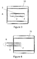
Figure 3 discloses a towing hitch assembly according to one aspect of the invention in retracted configuration. -
Figure 4 discloses a towing hitch assembly according toFigure 3 in extended configuration. -
Figure 5 discloses a locking device of the first part. -
Figure 6 discloses a locking device according toFigure 5 when engaged to an upper side of a towing vehicle. -
Figure 7 discloses a towing hitch assembly and a towing system according to one aspect of the invention. -
Figure 8 discloses a towing hitch assembly according to the invention connected to a towing vehicle. -
Figure 9 discloses a towing hitch assembly and a towing system according to one aspect of the invention. -
Figure 10a-d Function of the locking device is disclosed. -
Figure 11a and 11b a first part with ball bushings is disclosed. - The general object or idea of embodiments of the present disclosure is to address at least one or some of the disadvantages with the prior art solutions described above as well as below. The various steps described below in connection with the figures should be primarily understood in a logical sense.
- The terminology used herein is for the purpose of describing particular aspects of the disclosure only, and is not intended to limit the disclosure to any particular embodiment. As used herein, the singular forms "a", "an" and "the" are intended to include the plural forms as well, unless the context clearly indicates otherwise.
- According to
Figure 1 it is disclosed atowing hitch assembly 1. The towing hitch assembly has asecond part 3 that is slidably engaged in afirst part 2. Thesecond part 3 further has afront end 10 and aback end 11. Theback end 11 can be connected to aretraction device 5, as seen inFigure 7 . The connection between theback end 11 and theretraction device 5 can be made by means of anopening 12 in theback end 11. - The function of the towing
hitch assembly 1 is the following. It is attached to acarrier vehicle 15 underside. A towingvehicle 20 passes under thecarrier vehicle 15 and engages aconnection section 4 of thefirst part 2; see for exampleFigures 7 and 9 . As the towingvehicle 20 passes under thecarrier vehicle 15, the second part is drawn from a retracted position A to an extended configuration B, as seen inFigure 3 and 4 . -
First part 2 is attachable to acarrier vehicle 15, seefigure 3 and 4 . In general thefirst part 2 can be made from two essentially parallel tubes. For lowering friction inside the tubes there can be provided a lubricant, such that thesecond part 3 can slide with ease inside thefirst part 2. If more guidance is desired it is possible to provide thefirst part 2 withball bushings 47, as can be seen inFigure 11a and 11b with twoball bushings 47 at a distance from each other in each tube the friction is considerably lower and the guiding of thesecond part 3 inside thefirst part 2 is much improved. However the tube configuration is not mandatory, thefirst part 2 can be made up from for example squared bars, with a hole. Thefirst part 2 can also be made from a rail and wheel assembly. - The
second part 3 is best seen inFigure 1 and Figure 2 . Thesecond part 3 comprises a connectingfront end 10, a connectingsection 4, alocking device 9, and aback end 11. The features will be discussed further below. Thesecond part 3 comprises preferably twolongitudinal tubes 14 that can slide inside thefirst part 2. For the function of the towinghitch assembly 1, it is important that this sliding is performed with as low friction as possible. Even though thetubes 14 are shown to have a circular shape, this is to be understood to not be a mandatory shape. Thetubes 14 of thesecond part 3 could also have a square section, as long as thefirst part 2 is adapted for good sliding ability. Thetubes 14 of thesecond part 3 need not be completely straight, even though this is preferred for the best sliding ability. - The
front end 10 of the first part has a rounded shape. This shape allows for thesecond part 3 to slide forward in thefirst part 2 without hooking into acarrier vehicle 15 during extension. Thefront end 10 is preferably provided at an angle to the main length of thesecond part 3. The angle ensures that when disconnecting from a towingvehicle 20, thesecond part 3 cannot hook into protrusions as it slides back. The angle also provides for a towingvehicle 20 that is in the operation to connect to the connectingsection 4 by performing moving rearwards towards the towinghitch assembly 1. In particular it is favourable if the towingvehicle 20 has a resilient connectingdevice 22, the angle helps to push the connectingdevice 22 downwards such that it can connect to the connectingsection 4. - The
rear end 11 is angled in the same manner as thefront end 10. In particular it is favourable if the towingvehicle 20 has a resilient connectingdevice 22, the angle helps to push the connectingdevice 22 downwards such that it can connect to the connectingsection 4, when the towingvehicle 20 enters from therear end 11. As there is no need for a rounded shape for therear end 11 it can be made with a simple shape as a squared shape. The back end is also provided with arecess 12 for attachment of a retraction device that will be described below. Therecess 12 is of course easiest made as a through hole. But it is of course possible to provide an attached hook or an angled edge or any other way of attachment. - The
locking device 9 is provided in a groove in the middle of acentral section 40 of the first part. Thelocking device 9 is preferably made as an irregularly shaped element, as seen inFigure 5 and 6 . A throughhole 41 is provided. By applying the throughhole 41 such that it does not run through the centre ofgravity 42 of thelocking device 9, the locking device is arranged to swing into a resting position. When a towing vehicle passes by the locking device, it is swung up and remains resting on anupper side 21 of a towingvehicle 20. By this position the locking device, together with a not disclosed rim, prevents thesecond part 3 from sliding back under thecarrier vehicle 15. Other locking systems are of course thinkable. The presentedlocking device 9 is particularly simple and allows for the important function to allow for automatic retraction of thesecond part 3 after usage. Infigures 10a-d the function can be seen. Thelocking device 9 locks to theupper side 21 of a towingvehicle 20. InFigure 10a the towingvehicle 20 moves into position according to thearrow 45. Thelocking device 9 is rotated clockwise past arim 44 on the carryingvehicle 15, in direction ofarrow 9a. InFigure 10b thelocking device 9 is in locked position against theupper side 21 of a towingvehicle 20. If the carrying vehicle seeks to approach the towing vehicle it will be prevented to do this by thelocking device 9 as thelocking device 9 will be pushed against both therim 44 and theupper side 21. Thus oscillation between the towingvehicle 20 and the carryingvehicle 15 is avoided. InFigure 10c the towingvehicle 20 has disconnected from the connectingsection 4 of the towinghitch assembly 1. Thesecond part 3 of the towinghitch assembly 1 can thus retract backwards as the towingvehicle 20 continues forward in direction ofarrow 46. Theupper side 21 is no longer present under thelocking device 9 and thus thelocking device 9 can rotate,arrow 9b, such that it allows for the retraction of thesecond part 3. This is further presented inFigure 10d , where thelocking device 9 moves with thesecond part 3 in the direction of thearrow 9c under therim 44. - The connecting
section 4 is preferably made up of arecess 6, seeFigure 1 and 2 . Therecess 6 is positioned closer to thefront end 10 than theback end 11 of thesecond part 3. Therecess 6 is in general of triangular shape. The triangular shape is advantageously positioned such that onecorner 7 of the triangular shape is in line with thefront end 10, seeFigure 2 . This means that thecorner 7 is positioned such that at towing in a straight line, the corner will be in contact with connectingdevice 22 of a towingvehicle 20, seeFigure 9 . Further, therecess 6 with a triangular shape can guide the connectingdevice 22. This is possible as the connecting device will hook up from the base line of therecess 6. That is, the connectingdevice 22 will pass the carrier vehicle from back to front and thus also along the recess from thebase line 42 to thecorner 7. The sides of the triangular shape will thus guide the connectingdevice 22 such that it easily can engage thecorner 7. The connectingsection 4 further is advantageously provided with acover plate 13. Thecover plate 13 guides the connectingdevice 22 before it has reached thecorner 7. Thecover plate 13 prevents the connectingdevice 22 from extending through therecess 6. Thecover plate 13 is mainly guiding the connectingdevice 22 to thecorner 7 where it can protrude upwards freely and be supported by therim 43 in longitudinal direction. If the connectingdevice 22 would protrude freely upwards in thewhole recess 6, theupper side 21 of a towing vehicle would risk touching thesecond part 3, and prevent guiding of the connectingdevice 22 forward in therecess 6. This is not ideal as it could obstruct the free movement of a towingvehicle 20. Thecover plate 13 preferably has a roundededge 43 which keeps an engaged towingvehicle 20 in position within a smaller recess that comprises thecorner 7 and therounded edge 43. This provides for a better operation when towing thecarrier vehicle 15. - The
retraction device 5 can be seen inFigure 7 and 9 . Theretraction device 5 is preferably a helical spring. It should be attached to thesecond part 3 of the towinghitch assembly 1, and to thecarrier vehicle 15 frame. Theretraction device 5 could also be made from agas spring 5a or a combination of a gas spring or a helical spring. Other designs are also thinkable of course. It is possible to apply an electrical drive mechanism that retracts thesecond part 3. It is also possible to apply the towing hitch assembly at an angle and to let gravitation perform the retraction movement. That is the towinghitch assembly 1 is provided with thesecond part 3 higher than thefirst part 2 and all at an angle. Then thesecond part 3 could by gravity slide backwards after disconnection of a towingvehicle 20 has occurred. The operation of theretraction device 5 is to apply a retraction force, to retract the first part from an extended configuration A to the retracted configuration B. It is also an aim to keep thesecond part 3 in the retracted configuration. By having this way of keeping thesecond part 3 in retracted position, this provides for possibility to extract thesecond part 3 without having to unlock any extra locks etc. - It is further disclosed a towing system comprising a towing
hitch assembly 1 as described above, acarrier vehicle 15 and a towingvehicle 20. - The
carrier vehicle 15 is preferably built from a structure of tubes. The carrier vehicle is preferably adapted for indoor use. Thus it can be made in a very simple manner. The limited travel speed for the carrier vehicle is preferably 15 km/h, more preferably 10 km/h or more preferable 7 km/h, in particular 3 km/h. The low speed limit provides for that the carrier vehicle can have a very simple configuration. Thecarrier vehicle 15 preferably comprises at least two swivellingwheels 16, seeFigure 7 . There can bemore swivelling wheels 16 if desired. And of course there can be more than four wheels. For example there can be a configuration with two swivelling wheels at the front and back of the carrier vehicle and two wheels around the middle in longitudinal direction. Preferably, in this configuration, the middle wheels are linear wheels with no swivelling function. A preferred configuration is two swivellingwheels 16 at the end where the towing hitch assembly can protrude and twolinear wheels 16a at the other end, as seen inFigure 7 . This gives a stable operation and good operation when changing direction. Also the maximal total weight of thecarrier vehicle 15 is preferred to be 400 kg or preferably below 200 kg. The advantage of providing a maximum total weight of 400 kg, or even 200 kg, is that the basic design can be kept simple. It can be made up by a simple frame work construction. - The towing
vehicle 20 is preferably an electrical vehicle. The power to the towingvehicle 20 is preferably provided from an internal battery that is rechargeable. The important design of the towing vehicle is that it is lower than the height over ground where the towinghitch assembly 1 is attached to thecarrier vehicle 15. A mayor aspect of the present disclosure is that at operation, the towingvehicle 20 passes in full under the carrier vehicle and engages the connectingsection 4 of thesecond part 3 of the towing hitch assembly. And the towingvehicle 20 then continues its movement in the direction of the towinghitch assembly 1 and extracts the first part, such that the towinghitch assembly 1 attains the extracted configuration as seen inFigure 4 . The engagement of the towingvehicle 20 is preferably made by the connectingdevice 22, i.e. thehigh point 22 of the towingvehicle 20. The high point/connectingdevice 22 is preferably apin 22. Thepin 22 can have a spring resilient function such that when it is pressed down from above it moves resiliently downwards. This provides for an easy engagement of the connectingsection 4 as the pin can be partly pressed down by first therear end 11 of the first part and then be more pressed down by themiddle part 40 as the towingvehicle 20 moves under the towinghitch assembly 1. When thepin 22 reaches the connectingsection 4 it can resiliently extend upwards and thereby engage therecess 6 and finally after guiding of thesides 8 reach thecorner 7 of therecess 6. If therecess 6 is not triangular, it will with less efficiency reach the end of therecess 6. After this the towingvehicle 20 can move the first part to its extracted configuration B and in doing that also extract theretraction device 5. The towingvehicle 20 is preferably an AGV or an auto guided vehicle, this means that it can operate on its own without direct human control. This means that it can be programmed to perform tasks and then perform them without any human intervention. Even if it is not preferred the towingvehicle 20 could be programmed to extract the towinghitch assembly 1 from the first configuration A to the second configuration B, by applying a rear ward movement in front of thecarrier vehicle 15, and then engage therecess 6 of the towinghitch assembly 1. And after this a change of direction of the AGV would extract thesecond part 3. - When releasing the first part, the towing vehicle preferably lowers the
high point 22. This is performed by a non-disclosed mechanism within the towingvehicle 20. After this is performed the towingvehicle 20 can move freely and theretraction device 5 retracts the first part and the towing hitch assembly attains its retracted position.
Claims (15)
- A towing hitch assembly (1), wherein the towing hitch assembly (1) comprises a first part (2) that is connectable to a carrier vehicle (15) and a second part (3) which is attachable to a towing vehicle (20), the second part (3) being slidably moveable relative to the first part (2), between a first retracted configuration (A), and a second extended configuration (B), characterized in that when the first part (2) is attached to a carrier vehicle (15), a towing vehicle (20) can by engaging a connecting section (4) of the second part (3), pull the second part (3) to the second extended configuration (B), wherein the second extended configuration (B) allows for towing the carrier vehicle (15), and wherein when a towing vehicle (20) disengages the connecting section, the second part (3) will attend the first retracted configuration (A) automatically, by means of an installed retraction device (5) acting to slidably retract the first part (2).
- A towing hitch assembly (1) according to claim 1, wherein the retracted second part (3) is kept in the first retracted configuration (A) by means of the retraction device (5).
- A towing hitch assembly (1) according claim 1 or 2, wherein the retraction device (5, 5a) comprises a helical spring (5) and/or a gas spring (5a).
- A towing hitch assembly (1) according any of the claims 1 - 3, wherein the connecting section (4) comprises a recess (6).
- A towing hitch assembly (1) according to claim 4, wherein the recess (6) has a triangular shape, preferably the recess (6) has a corner (7) of said triangular shape positioned in the main towing direction of a carrier vehicle (15), such that when connecting to the recess (6) guiding may be achieved by the angled sides (8) of the triangular shape.
- A towing hitch assembly (1) according to any of the claims above, wherein a locking device (9) is provided on the second part (3).
- A towing hitch assembly (1) according to claim 6, wherein the locking device (9) uses a side (21) of a towing vehicle (20) to be kept in locking position, wherein the side (21) is preferably an upper side (21) of a towing vehicle (20).
- A towing hitch assembly (1) according to claim 6 or 7, wherein the locking device (9) uses gravity to reach the correct positon for being able to engage a towing vehicle (20), preferably the correct position is reached by using a transversal axis that does not run through the centre of gravity of the locking device (9).
- A towing system comprising a towing vehicle (20), a carrier vehicle (15), and a towing hitch assembly (1) according to any of the claims 1-8 attached to the carrier vehicle (15).
- A towing system according to claim 9, wherein the carrier vehicle (15) comprises two swivelling wheels (16), preferably four swivelling wheels.
- A towing system according to claim 9 or 10, wherein the carrier vehicle (15) has a limited travel speed of 15 km/h, preferably 7 km/h, even more preferred 3 km/h, and/or the carrier vehicle (15) has a maximum total weight of 400 kg, preferably 200 kg.
- A towing system according to any of the claims 9-11, wherein the towing system is adapted for indoor use only.
- A towing system according to any of the claims 9-12 above, wherein the towing vehicle (20) has a high point (22) that engages the connecting section (4) of the towing hitch assembly (1), such that the towing vehicle (20) in full can pass under the towing hitch assembly (1) for engaging the connecting section (4).
- A towing system according to any of the claims 9-13, wherein the towing vehicle (20) is an auto guided vehicle, preferably being an electric vehicle.
- A towing system according to any of the claims 9-14, wherein the width of the towing vehicle (20) is smaller than the width of the carrier vehicle (15).
Priority Applications (2)
| Application Number | Priority Date | Filing Date | Title |
|---|---|---|---|
| EP15166796.1A EP3090887B1 (en) | 2015-05-07 | 2015-05-07 | A towing hitch assembly and a towing system |
| CN201610201402.7A CN106114090B (en) | 2015-05-07 | 2016-03-31 | Traction coupling assembly and traction system |
Applications Claiming Priority (1)
| Application Number | Priority Date | Filing Date | Title |
|---|---|---|---|
| EP15166796.1A EP3090887B1 (en) | 2015-05-07 | 2015-05-07 | A towing hitch assembly and a towing system |
Publications (2)
| Publication Number | Publication Date |
|---|---|
| EP3090887A1 true EP3090887A1 (en) | 2016-11-09 |
| EP3090887B1 EP3090887B1 (en) | 2019-09-25 |
Family
ID=53054941
Family Applications (1)
| Application Number | Title | Priority Date | Filing Date |
|---|---|---|---|
| EP15166796.1A Active EP3090887B1 (en) | 2015-05-07 | 2015-05-07 | A towing hitch assembly and a towing system |
Country Status (2)
| Country | Link |
|---|---|
| EP (1) | EP3090887B1 (en) |
| CN (1) | CN106114090B (en) |
Cited By (3)
| Publication number | Priority date | Publication date | Assignee | Title |
|---|---|---|---|---|
| US20160375736A1 (en) * | 2014-11-28 | 2016-12-29 | Sharmel Wilson | Dolly Stabilizer |
| KR20230042158A (en) * | 2021-09-17 | 2023-03-28 | 주식회사 크래블 | A system that assists in autonomous driving of mechanical tractors via human machine interface |
| DE102021212210A1 (en) | 2021-10-28 | 2023-05-04 | B.PRO GmbH | Hitch and pick-up device |
Families Citing this family (3)
| Publication number | Priority date | Publication date | Assignee | Title |
|---|---|---|---|---|
| CN110253008B (en) * | 2019-07-31 | 2021-01-01 | 广东韶钢松山股份有限公司 | Hot metal bottle tractor operation system |
| CN112549878B (en) * | 2019-09-10 | 2022-07-08 | 杭州海康机器人技术有限公司 | Tractor |
| CN111619681A (en) * | 2020-06-23 | 2020-09-04 | 北京海益同展信息科技有限公司 | Traction robot and conveying system and control method thereof |
Citations (2)
| Publication number | Priority date | Publication date | Assignee | Title |
|---|---|---|---|---|
| DE2939927A1 (en) * | 1979-10-02 | 1981-04-23 | Alf Sävsjö Claesson | Adjustable trailer chassis with interchangeable components - allows different types of trailer to be constructed on same chassis, with adjustment of tow rod length |
| GB2059896A (en) * | 1979-10-10 | 1981-04-29 | Clifton R J | Improvements in or relating to vehicle recovery tow bars |
Family Cites Families (7)
| Publication number | Priority date | Publication date | Assignee | Title |
|---|---|---|---|---|
| US3639164A (en) * | 1969-12-15 | 1972-02-01 | Gen Electric | Enameled metal substrates and method of forming |
| US5382042A (en) * | 1993-11-15 | 1995-01-17 | Mcphee; Steven J. | Towing device support |
| MX2013006200A (en) * | 2010-12-01 | 2013-07-29 | Hartwall K Oy Ab | Coupling arrangement for a dolly and a dolly. |
| GB2493764B (en) * | 2011-08-18 | 2017-10-18 | Storm Env Ltd | A Moveable Container comprising a Towing hitch assembly |
| CN203844559U (en) * | 2014-05-29 | 2014-09-24 | 安徽江淮汽车股份有限公司 | Trolley connecting device |
| CN203920300U (en) * | 2014-06-16 | 2014-11-05 | 苏州工业园区艾吉威自动化设备有限公司 | Automatically-unhooked and the hitch gear of AGV dolly afterbody traction |
| EP3090888B1 (en) * | 2015-05-04 | 2019-12-11 | Toyota Material Handling Manufacturing Sweden AB | A towing hitch assembly and a towing system |
-
2015
- 2015-05-07 EP EP15166796.1A patent/EP3090887B1/en active Active
-
2016
- 2016-03-31 CN CN201610201402.7A patent/CN106114090B/en active Active
Patent Citations (2)
| Publication number | Priority date | Publication date | Assignee | Title |
|---|---|---|---|---|
| DE2939927A1 (en) * | 1979-10-02 | 1981-04-23 | Alf Sävsjö Claesson | Adjustable trailer chassis with interchangeable components - allows different types of trailer to be constructed on same chassis, with adjustment of tow rod length |
| GB2059896A (en) * | 1979-10-10 | 1981-04-29 | Clifton R J | Improvements in or relating to vehicle recovery tow bars |
Cited By (4)
| Publication number | Priority date | Publication date | Assignee | Title |
|---|---|---|---|---|
| US20160375736A1 (en) * | 2014-11-28 | 2016-12-29 | Sharmel Wilson | Dolly Stabilizer |
| US9987893B2 (en) * | 2014-11-28 | 2018-06-05 | Sharmel Wilson | Dolly stabilizer |
| KR20230042158A (en) * | 2021-09-17 | 2023-03-28 | 주식회사 크래블 | A system that assists in autonomous driving of mechanical tractors via human machine interface |
| DE102021212210A1 (en) | 2021-10-28 | 2023-05-04 | B.PRO GmbH | Hitch and pick-up device |
Also Published As
| Publication number | Publication date |
|---|---|
| CN106114090A (en) | 2016-11-16 |
| EP3090887B1 (en) | 2019-09-25 |
| CN106114090B (en) | 2020-06-02 |
Similar Documents
| Publication | Publication Date | Title |
|---|---|---|
| EP3090887B1 (en) | A towing hitch assembly and a towing system | |
| US11897126B2 (en) | System for connecting an autonomous mobile robot | |
| EP3250404B1 (en) | Drive system for a movable roof part of a roof module of a motor vehicle | |
| US9862298B2 (en) | Trailer dovetail actuating system | |
| DE102007004704A1 (en) | Pushchair for use with e.g. industrial truck, has electric motor and electric power storage formed in housing of drive unit, and drive attached at motor, where drive wheel is lowerable and liftable together with drive unit | |
| EP2865585B1 (en) | Transport set | |
| US11745551B2 (en) | Tow bar assembly | |
| CN102416909A (en) | Deployable roof rack system | |
| CN110803257A (en) | Unmanned navigation equipment collecting and releasing system | |
| DE202011051446U1 (en) | Dolly | |
| EP3177467B1 (en) | Set of trolleys configured to be towed | |
| EP2692681B1 (en) | Hoisting device provided with a mechanical interlocking system | |
| EP2518007B1 (en) | Industrial truck, in particular forklift equipped with a counterweight | |
| EP3090888B1 (en) | A towing hitch assembly and a towing system | |
| EP2660102B1 (en) | Equipment for recovering broken-down vehicles and system provided with such equipment | |
| CN109205210B (en) | Moving device for automatic collection and distribution of carrying compartment body and double-compartment equipment | |
| EP2657177A1 (en) | Trolley for the towing of vehicles | |
| CN215205019U (en) | Car door transfer cart | |
| CN106760773A (en) | Parking conveying arrangement and lugs and parking method | |
| EP3315333B1 (en) | Towing hitch assembly | |
| CN209757325U (en) | AGV car for conveying fused zirconia corundum bricks | |
| CN215318804U (en) | Intelligent bottom layer control device of omnidirectional mobile robot | |
| CN203698472U (en) | Vehicle body assembly transferring trolley | |
| CN219446997U (en) | Portable roadway car arrester for coal mine track | |
| CN113003482B (en) | AGV (automatic guided vehicle) matched with wire vehicle |
Legal Events
| Date | Code | Title | Description |
|---|---|---|---|
| PUAI | Public reference made under article 153(3) epc to a published international application that has entered the european phase |
Free format text: ORIGINAL CODE: 0009012 |
|
| AK | Designated contracting states |
Kind code of ref document: A1 Designated state(s): AL AT BE BG CH CY CZ DE DK EE ES FI FR GB GR HR HU IE IS IT LI LT LU LV MC MK MT NL NO PL PT RO RS SE SI SK SM TR |
|
| AX | Request for extension of the european patent |
Extension state: BA ME |
|
| 17P | Request for examination filed |
Effective date: 20170502 |
|
| RBV | Designated contracting states (corrected) |
Designated state(s): AL AT BE BG CH CY CZ DE DK EE ES FI FR GB GR HR HU IE IS IT LI LT LU LV MC MK MT NL NO PL PT RO RS SE SI SK SM TR |
|
| STAA | Information on the status of an ep patent application or granted ep patent |
Free format text: STATUS: REQUEST FOR EXAMINATION WAS MADE |
|
| RAP1 | Party data changed (applicant data changed or rights of an application transferred) |
Owner name: TOYOTA MATERIAL HANDLING MANUFACTURING SWEDEN AB |
|
| GRAP | Despatch of communication of intention to grant a patent |
Free format text: ORIGINAL CODE: EPIDOSNIGR1 |
|
| STAA | Information on the status of an ep patent application or granted ep patent |
Free format text: STATUS: GRANT OF PATENT IS INTENDED |
|
| INTG | Intention to grant announced |
Effective date: 20190412 |
|
| GRAS | Grant fee paid |
Free format text: ORIGINAL CODE: EPIDOSNIGR3 |
|
| GRAA | (expected) grant |
Free format text: ORIGINAL CODE: 0009210 |
|
| STAA | Information on the status of an ep patent application or granted ep patent |
Free format text: STATUS: THE PATENT HAS BEEN GRANTED |
|
| AK | Designated contracting states |
Kind code of ref document: B1 Designated state(s): AL AT BE BG CH CY CZ DE DK EE ES FI FR GB GR HR HU IE IS IT LI LT LU LV MC MK MT NL NO PL PT RO RS SE SI SK SM TR |
|
| REG | Reference to a national code |
Ref country code: GB Ref legal event code: FG4D |
|
| REG | Reference to a national code |
Ref country code: CH Ref legal event code: EP |
|
| REG | Reference to a national code |
Ref country code: AT Ref legal event code: REF Ref document number: 1183459 Country of ref document: AT Kind code of ref document: T Effective date: 20191015 |
|
| REG | Reference to a national code |
Ref country code: IE Ref legal event code: FG4D |
|
| REG | Reference to a national code |
Ref country code: DE Ref legal event code: R096 Ref document number: 602015038544 Country of ref document: DE |
|
| REG | Reference to a national code |
Ref country code: SE Ref legal event code: TRGR |
|
| REG | Reference to a national code |
Ref country code: NL Ref legal event code: MP Effective date: 20190925 |
|
| PG25 | Lapsed in a contracting state [announced via postgrant information from national office to epo] |
Ref country code: NO Free format text: LAPSE BECAUSE OF FAILURE TO SUBMIT A TRANSLATION OF THE DESCRIPTION OR TO PAY THE FEE WITHIN THE PRESCRIBED TIME-LIMIT Effective date: 20191225 Ref country code: HR Free format text: LAPSE BECAUSE OF FAILURE TO SUBMIT A TRANSLATION OF THE DESCRIPTION OR TO PAY THE FEE WITHIN THE PRESCRIBED TIME-LIMIT Effective date: 20190925 Ref country code: FI Free format text: LAPSE BECAUSE OF FAILURE TO SUBMIT A TRANSLATION OF THE DESCRIPTION OR TO PAY THE FEE WITHIN THE PRESCRIBED TIME-LIMIT Effective date: 20190925 Ref country code: LT Free format text: LAPSE BECAUSE OF FAILURE TO SUBMIT A TRANSLATION OF THE DESCRIPTION OR TO PAY THE FEE WITHIN THE PRESCRIBED TIME-LIMIT Effective date: 20190925 Ref country code: BG Free format text: LAPSE BECAUSE OF FAILURE TO SUBMIT A TRANSLATION OF THE DESCRIPTION OR TO PAY THE FEE WITHIN THE PRESCRIBED TIME-LIMIT Effective date: 20191225 |
|
| REG | Reference to a national code |
Ref country code: LT Ref legal event code: MG4D |
|
| PG25 | Lapsed in a contracting state [announced via postgrant information from national office to epo] |
Ref country code: GR Free format text: LAPSE BECAUSE OF FAILURE TO SUBMIT A TRANSLATION OF THE DESCRIPTION OR TO PAY THE FEE WITHIN THE PRESCRIBED TIME-LIMIT Effective date: 20191226 Ref country code: RS Free format text: LAPSE BECAUSE OF FAILURE TO SUBMIT A TRANSLATION OF THE DESCRIPTION OR TO PAY THE FEE WITHIN THE PRESCRIBED TIME-LIMIT Effective date: 20190925 Ref country code: LV Free format text: LAPSE BECAUSE OF FAILURE TO SUBMIT A TRANSLATION OF THE DESCRIPTION OR TO PAY THE FEE WITHIN THE PRESCRIBED TIME-LIMIT Effective date: 20190925 |
|
| REG | Reference to a national code |
Ref country code: AT Ref legal event code: MK05 Ref document number: 1183459 Country of ref document: AT Kind code of ref document: T Effective date: 20190925 |
|
| PG25 | Lapsed in a contracting state [announced via postgrant information from national office to epo] |
Ref country code: ES Free format text: LAPSE BECAUSE OF FAILURE TO SUBMIT A TRANSLATION OF THE DESCRIPTION OR TO PAY THE FEE WITHIN THE PRESCRIBED TIME-LIMIT Effective date: 20190925 Ref country code: AL Free format text: LAPSE BECAUSE OF FAILURE TO SUBMIT A TRANSLATION OF THE DESCRIPTION OR TO PAY THE FEE WITHIN THE PRESCRIBED TIME-LIMIT Effective date: 20190925 Ref country code: NL Free format text: LAPSE BECAUSE OF FAILURE TO SUBMIT A TRANSLATION OF THE DESCRIPTION OR TO PAY THE FEE WITHIN THE PRESCRIBED TIME-LIMIT Effective date: 20190925 Ref country code: PL Free format text: LAPSE BECAUSE OF FAILURE TO SUBMIT A TRANSLATION OF THE DESCRIPTION OR TO PAY THE FEE WITHIN THE PRESCRIBED TIME-LIMIT Effective date: 20190925 Ref country code: PT Free format text: LAPSE BECAUSE OF FAILURE TO SUBMIT A TRANSLATION OF THE DESCRIPTION OR TO PAY THE FEE WITHIN THE PRESCRIBED TIME-LIMIT Effective date: 20200127 Ref country code: RO Free format text: LAPSE BECAUSE OF FAILURE TO SUBMIT A TRANSLATION OF THE DESCRIPTION OR TO PAY THE FEE WITHIN THE PRESCRIBED TIME-LIMIT Effective date: 20190925 Ref country code: EE Free format text: LAPSE BECAUSE OF FAILURE TO SUBMIT A TRANSLATION OF THE DESCRIPTION OR TO PAY THE FEE WITHIN THE PRESCRIBED TIME-LIMIT Effective date: 20190925 Ref country code: AT Free format text: LAPSE BECAUSE OF FAILURE TO SUBMIT A TRANSLATION OF THE DESCRIPTION OR TO PAY THE FEE WITHIN THE PRESCRIBED TIME-LIMIT Effective date: 20190925 Ref country code: IT Free format text: LAPSE BECAUSE OF FAILURE TO SUBMIT A TRANSLATION OF THE DESCRIPTION OR TO PAY THE FEE WITHIN THE PRESCRIBED TIME-LIMIT Effective date: 20190925 |
|
| PG25 | Lapsed in a contracting state [announced via postgrant information from national office to epo] |
Ref country code: SM Free format text: LAPSE BECAUSE OF FAILURE TO SUBMIT A TRANSLATION OF THE DESCRIPTION OR TO PAY THE FEE WITHIN THE PRESCRIBED TIME-LIMIT Effective date: 20190925 Ref country code: CZ Free format text: LAPSE BECAUSE OF FAILURE TO SUBMIT A TRANSLATION OF THE DESCRIPTION OR TO PAY THE FEE WITHIN THE PRESCRIBED TIME-LIMIT Effective date: 20190925 Ref country code: IS Free format text: LAPSE BECAUSE OF FAILURE TO SUBMIT A TRANSLATION OF THE DESCRIPTION OR TO PAY THE FEE WITHIN THE PRESCRIBED TIME-LIMIT Effective date: 20200224 Ref country code: SK Free format text: LAPSE BECAUSE OF FAILURE TO SUBMIT A TRANSLATION OF THE DESCRIPTION OR TO PAY THE FEE WITHIN THE PRESCRIBED TIME-LIMIT Effective date: 20190925 |
|
| REG | Reference to a national code |
Ref country code: DE Ref legal event code: R097 Ref document number: 602015038544 Country of ref document: DE |
|
| PG2D | Information on lapse in contracting state deleted |
Ref country code: IS |
|
| PG25 | Lapsed in a contracting state [announced via postgrant information from national office to epo] |
Ref country code: DK Free format text: LAPSE BECAUSE OF FAILURE TO SUBMIT A TRANSLATION OF THE DESCRIPTION OR TO PAY THE FEE WITHIN THE PRESCRIBED TIME-LIMIT Effective date: 20190925 Ref country code: IS Free format text: LAPSE BECAUSE OF FAILURE TO SUBMIT A TRANSLATION OF THE DESCRIPTION OR TO PAY THE FEE WITHIN THE PRESCRIBED TIME-LIMIT Effective date: 20200126 |
|
| PLBE | No opposition filed within time limit |
Free format text: ORIGINAL CODE: 0009261 |
|
| STAA | Information on the status of an ep patent application or granted ep patent |
Free format text: STATUS: NO OPPOSITION FILED WITHIN TIME LIMIT |
|
| 26N | No opposition filed |
Effective date: 20200626 |
|
| PG25 | Lapsed in a contracting state [announced via postgrant information from national office to epo] |
Ref country code: SI Free format text: LAPSE BECAUSE OF FAILURE TO SUBMIT A TRANSLATION OF THE DESCRIPTION OR TO PAY THE FEE WITHIN THE PRESCRIBED TIME-LIMIT Effective date: 20190925 |
|
| PG25 | Lapsed in a contracting state [announced via postgrant information from national office to epo] |
Ref country code: MC Free format text: LAPSE BECAUSE OF FAILURE TO SUBMIT A TRANSLATION OF THE DESCRIPTION OR TO PAY THE FEE WITHIN THE PRESCRIBED TIME-LIMIT Effective date: 20190925 Ref country code: CH Free format text: LAPSE BECAUSE OF NON-PAYMENT OF DUE FEES Effective date: 20200531 Ref country code: LI Free format text: LAPSE BECAUSE OF NON-PAYMENT OF DUE FEES Effective date: 20200531 |
|
| REG | Reference to a national code |
Ref country code: BE Ref legal event code: MM Effective date: 20200531 |
|
| PG25 | Lapsed in a contracting state [announced via postgrant information from national office to epo] |
Ref country code: LU Free format text: LAPSE BECAUSE OF NON-PAYMENT OF DUE FEES Effective date: 20200507 |
|
| PG25 | Lapsed in a contracting state [announced via postgrant information from national office to epo] |
Ref country code: IE Free format text: LAPSE BECAUSE OF NON-PAYMENT OF DUE FEES Effective date: 20200507 |
|
| PG25 | Lapsed in a contracting state [announced via postgrant information from national office to epo] |
Ref country code: BE Free format text: LAPSE BECAUSE OF NON-PAYMENT OF DUE FEES Effective date: 20200531 |
|
| PG25 | Lapsed in a contracting state [announced via postgrant information from national office to epo] |
Ref country code: TR Free format text: LAPSE BECAUSE OF FAILURE TO SUBMIT A TRANSLATION OF THE DESCRIPTION OR TO PAY THE FEE WITHIN THE PRESCRIBED TIME-LIMIT Effective date: 20190925 Ref country code: MT Free format text: LAPSE BECAUSE OF FAILURE TO SUBMIT A TRANSLATION OF THE DESCRIPTION OR TO PAY THE FEE WITHIN THE PRESCRIBED TIME-LIMIT Effective date: 20190925 Ref country code: CY Free format text: LAPSE BECAUSE OF FAILURE TO SUBMIT A TRANSLATION OF THE DESCRIPTION OR TO PAY THE FEE WITHIN THE PRESCRIBED TIME-LIMIT Effective date: 20190925 |
|
| PG25 | Lapsed in a contracting state [announced via postgrant information from national office to epo] |
Ref country code: MK Free format text: LAPSE BECAUSE OF FAILURE TO SUBMIT A TRANSLATION OF THE DESCRIPTION OR TO PAY THE FEE WITHIN THE PRESCRIBED TIME-LIMIT Effective date: 20190925 |
|
| P01 | Opt-out of the competence of the unified patent court (upc) registered |
Effective date: 20230526 |
|
| PGFP | Annual fee paid to national office [announced via postgrant information from national office to epo] |
Ref country code: GB Payment date: 20240521 Year of fee payment: 10 |
|
| PGFP | Annual fee paid to national office [announced via postgrant information from national office to epo] |
Ref country code: DE Payment date: 20240529 Year of fee payment: 10 |
|
| PGFP | Annual fee paid to national office [announced via postgrant information from national office to epo] |
Ref country code: FR Payment date: 20240527 Year of fee payment: 10 |
|
| PGFP | Annual fee paid to national office [announced via postgrant information from national office to epo] |
Ref country code: SE Payment date: 20240524 Year of fee payment: 10 |