EP3090858A2 - Welding method free of bead trimming and double-head cutting saw with automatic processing function - Google Patents
Welding method free of bead trimming and double-head cutting saw with automatic processing function Download PDFInfo
- Publication number
- EP3090858A2 EP3090858A2 EP16154241.0A EP16154241A EP3090858A2 EP 3090858 A2 EP3090858 A2 EP 3090858A2 EP 16154241 A EP16154241 A EP 16154241A EP 3090858 A2 EP3090858 A2 EP 3090858A2
- Authority
- EP
- European Patent Office
- Prior art keywords
- saw
- head
- cutting
- section bar
- welding
- Prior art date
- Legal status (The legal status is an assumption and is not a legal conclusion. Google has not performed a legal analysis and makes no representation as to the accuracy of the status listed.)
- Granted
Links
Images



Classifications
-
- B—PERFORMING OPERATIONS; TRANSPORTING
- B29—WORKING OF PLASTICS; WORKING OF SUBSTANCES IN A PLASTIC STATE IN GENERAL
- B29C—SHAPING OR JOINING OF PLASTICS; SHAPING OF MATERIAL IN A PLASTIC STATE, NOT OTHERWISE PROVIDED FOR; AFTER-TREATMENT OF THE SHAPED PRODUCTS, e.g. REPAIRING
- B29C66/00—General aspects of processes or apparatus for joining preformed parts
- B29C66/01—General aspects dealing with the joint area or with the area to be joined
- B29C66/05—Particular design of joint configurations
- B29C66/10—Particular design of joint configurations particular design of the joint cross-sections
- B29C66/11—Joint cross-sections comprising a single joint-segment, i.e. one of the parts to be joined comprising a single joint-segment in the joint cross-section
- B29C66/116—Single bevelled joints, i.e. one of the parts to be joined being bevelled in the joint area
- B29C66/1162—Single bevel to bevel joints, e.g. mitre joints
-
- B—PERFORMING OPERATIONS; TRANSPORTING
- B23—MACHINE TOOLS; METAL-WORKING NOT OTHERWISE PROVIDED FOR
- B23C—MILLING
- B23C3/00—Milling particular work; Special milling operations; Machines therefor
- B23C3/002—Milling elongated workpieces
-
- B—PERFORMING OPERATIONS; TRANSPORTING
- B23—MACHINE TOOLS; METAL-WORKING NOT OTHERWISE PROVIDED FOR
- B23C—MILLING
- B23C3/00—Milling particular work; Special milling operations; Machines therefor
- B23C3/12—Trimming or finishing edges, e.g. deburring welded corners
- B23C3/128—Trimming or finishing edges of doors and windows
-
- B—PERFORMING OPERATIONS; TRANSPORTING
- B23—MACHINE TOOLS; METAL-WORKING NOT OTHERWISE PROVIDED FOR
- B23C—MILLING
- B23C3/00—Milling particular work; Special milling operations; Machines therefor
- B23C3/28—Grooving workpieces
- B23C3/30—Milling straight grooves, e.g. keyways
- B23C3/305—Milling straight grooves, e.g. keyways in which more than one milling tool is used simultaneously, e.g. for sheet material
-
- B—PERFORMING OPERATIONS; TRANSPORTING
- B23—MACHINE TOOLS; METAL-WORKING NOT OTHERWISE PROVIDED FOR
- B23D—PLANING; SLOTTING; SHEARING; BROACHING; SAWING; FILING; SCRAPING; LIKE OPERATIONS FOR WORKING METAL BY REMOVING MATERIAL, NOT OTHERWISE PROVIDED FOR
- B23D45/00—Sawing machines or sawing devices with circular saw blades or with friction saw discs
- B23D45/04—Sawing machines or sawing devices with circular saw blades or with friction saw discs with a circular saw blade or the stock carried by a pivoted lever
- B23D45/042—Sawing machines or sawing devices with circular saw blades or with friction saw discs with a circular saw blade or the stock carried by a pivoted lever with the saw blade carried by a pivoted lever
- B23D45/046—Sawing machines or sawing devices with circular saw blades or with friction saw discs with a circular saw blade or the stock carried by a pivoted lever with the saw blade carried by a pivoted lever the pivoted lever being mounted on a carriage
-
- B—PERFORMING OPERATIONS; TRANSPORTING
- B23—MACHINE TOOLS; METAL-WORKING NOT OTHERWISE PROVIDED FOR
- B23D—PLANING; SLOTTING; SHEARING; BROACHING; SAWING; FILING; SCRAPING; LIKE OPERATIONS FOR WORKING METAL BY REMOVING MATERIAL, NOT OTHERWISE PROVIDED FOR
- B23D45/00—Sawing machines or sawing devices with circular saw blades or with friction saw discs
- B23D45/14—Sawing machines or sawing devices with circular saw blades or with friction saw discs for cutting otherwise than in a plane perpendicular to the axis of the stock, e.g. for making a mitred cut
- B23D45/143—Sawing machines or sawing devices with circular saw blades or with friction saw discs for cutting otherwise than in a plane perpendicular to the axis of the stock, e.g. for making a mitred cut with a plurality of circular saw blades
-
- B—PERFORMING OPERATIONS; TRANSPORTING
- B29—WORKING OF PLASTICS; WORKING OF SUBSTANCES IN A PLASTIC STATE IN GENERAL
- B29C—SHAPING OR JOINING OF PLASTICS; SHAPING OF MATERIAL IN A PLASTIC STATE, NOT OTHERWISE PROVIDED FOR; AFTER-TREATMENT OF THE SHAPED PRODUCTS, e.g. REPAIRING
- B29C65/00—Joining or sealing of preformed parts, e.g. welding of plastics materials; Apparatus therefor
- B29C65/02—Joining or sealing of preformed parts, e.g. welding of plastics materials; Apparatus therefor by heating, with or without pressure
-
- B—PERFORMING OPERATIONS; TRANSPORTING
- B29—WORKING OF PLASTICS; WORKING OF SUBSTANCES IN A PLASTIC STATE IN GENERAL
- B29C—SHAPING OR JOINING OF PLASTICS; SHAPING OF MATERIAL IN A PLASTIC STATE, NOT OTHERWISE PROVIDED FOR; AFTER-TREATMENT OF THE SHAPED PRODUCTS, e.g. REPAIRING
- B29C66/00—General aspects of processes or apparatus for joining preformed parts
- B29C66/01—General aspects dealing with the joint area or with the area to be joined
- B29C66/02—Preparation of the material, in the area to be joined, prior to joining or welding
- B29C66/022—Mechanical pre-treatments, e.g. reshaping
- B29C66/0224—Mechanical pre-treatments, e.g. reshaping with removal of material
- B29C66/02241—Cutting, e.g. by using waterjets, or sawing
-
- B—PERFORMING OPERATIONS; TRANSPORTING
- B29—WORKING OF PLASTICS; WORKING OF SUBSTANCES IN A PLASTIC STATE IN GENERAL
- B29C—SHAPING OR JOINING OF PLASTICS; SHAPING OF MATERIAL IN A PLASTIC STATE, NOT OTHERWISE PROVIDED FOR; AFTER-TREATMENT OF THE SHAPED PRODUCTS, e.g. REPAIRING
- B29C66/00—General aspects of processes or apparatus for joining preformed parts
- B29C66/01—General aspects dealing with the joint area or with the area to be joined
- B29C66/32—Measures for keeping the burr form under control; Avoiding burr formation; Shaping the burr
- B29C66/322—Providing cavities in the joined article to collect the burr
-
- B—PERFORMING OPERATIONS; TRANSPORTING
- B29—WORKING OF PLASTICS; WORKING OF SUBSTANCES IN A PLASTIC STATE IN GENERAL
- B29C—SHAPING OR JOINING OF PLASTICS; SHAPING OF MATERIAL IN A PLASTIC STATE, NOT OTHERWISE PROVIDED FOR; AFTER-TREATMENT OF THE SHAPED PRODUCTS, e.g. REPAIRING
- B29C66/00—General aspects of processes or apparatus for joining preformed parts
- B29C66/50—General aspects of joining tubular articles; General aspects of joining long products, i.e. bars or profiled elements; General aspects of joining single elements to tubular articles, hollow articles or bars; General aspects of joining several hollow-preforms to form hollow or tubular articles
- B29C66/51—Joining tubular articles, profiled elements or bars; Joining single elements to tubular articles, hollow articles or bars; Joining several hollow-preforms to form hollow or tubular articles
- B29C66/52—Joining tubular articles, bars or profiled elements
- B29C66/524—Joining profiled elements
- B29C66/5241—Joining profiled elements for forming coaxial connections, i.e. the profiled elements to be joined forming a zero angle relative to each other
-
- B—PERFORMING OPERATIONS; TRANSPORTING
- B29—WORKING OF PLASTICS; WORKING OF SUBSTANCES IN A PLASTIC STATE IN GENERAL
- B29C—SHAPING OR JOINING OF PLASTICS; SHAPING OF MATERIAL IN A PLASTIC STATE, NOT OTHERWISE PROVIDED FOR; AFTER-TREATMENT OF THE SHAPED PRODUCTS, e.g. REPAIRING
- B29C66/00—General aspects of processes or apparatus for joining preformed parts
- B29C66/50—General aspects of joining tubular articles; General aspects of joining long products, i.e. bars or profiled elements; General aspects of joining single elements to tubular articles, hollow articles or bars; General aspects of joining several hollow-preforms to form hollow or tubular articles
- B29C66/51—Joining tubular articles, profiled elements or bars; Joining single elements to tubular articles, hollow articles or bars; Joining several hollow-preforms to form hollow or tubular articles
- B29C66/52—Joining tubular articles, bars or profiled elements
- B29C66/524—Joining profiled elements
- B29C66/5243—Joining profiled elements for forming corner connections, e.g. for making window frames or V-shaped pieces
- B29C66/52431—Joining profiled elements for forming corner connections, e.g. for making window frames or V-shaped pieces with a right angle, e.g. for making L-shaped pieces
-
- B—PERFORMING OPERATIONS; TRANSPORTING
- B29—WORKING OF PLASTICS; WORKING OF SUBSTANCES IN A PLASTIC STATE IN GENERAL
- B29C—SHAPING OR JOINING OF PLASTICS; SHAPING OF MATERIAL IN A PLASTIC STATE, NOT OTHERWISE PROVIDED FOR; AFTER-TREATMENT OF THE SHAPED PRODUCTS, e.g. REPAIRING
- B29C66/00—General aspects of processes or apparatus for joining preformed parts
- B29C66/70—General aspects of processes or apparatus for joining preformed parts characterised by the composition, physical properties or the structure of the material of the parts to be joined; Joining with non-plastics material
- B29C66/71—General aspects of processes or apparatus for joining preformed parts characterised by the composition, physical properties or the structure of the material of the parts to be joined; Joining with non-plastics material characterised by the composition of the plastics material of the parts to be joined
-
- B—PERFORMING OPERATIONS; TRANSPORTING
- B29—WORKING OF PLASTICS; WORKING OF SUBSTANCES IN A PLASTIC STATE IN GENERAL
- B29C—SHAPING OR JOINING OF PLASTICS; SHAPING OF MATERIAL IN A PLASTIC STATE, NOT OTHERWISE PROVIDED FOR; AFTER-TREATMENT OF THE SHAPED PRODUCTS, e.g. REPAIRING
- B29C66/00—General aspects of processes or apparatus for joining preformed parts
- B29C66/70—General aspects of processes or apparatus for joining preformed parts characterised by the composition, physical properties or the structure of the material of the parts to be joined; Joining with non-plastics material
- B29C66/72—General aspects of processes or apparatus for joining preformed parts characterised by the composition, physical properties or the structure of the material of the parts to be joined; Joining with non-plastics material characterised by the structure of the material of the parts to be joined
- B29C66/725—General aspects of processes or apparatus for joining preformed parts characterised by the composition, physical properties or the structure of the material of the parts to be joined; Joining with non-plastics material characterised by the structure of the material of the parts to be joined being hollow-walled or honeycombs
- B29C66/7252—General aspects of processes or apparatus for joining preformed parts characterised by the composition, physical properties or the structure of the material of the parts to be joined; Joining with non-plastics material characterised by the structure of the material of the parts to be joined being hollow-walled or honeycombs hollow-walled
- B29C66/72523—General aspects of processes or apparatus for joining preformed parts characterised by the composition, physical properties or the structure of the material of the parts to be joined; Joining with non-plastics material characterised by the structure of the material of the parts to be joined being hollow-walled or honeycombs hollow-walled multi-channelled or multi-tubular
-
- B—PERFORMING OPERATIONS; TRANSPORTING
- B29—WORKING OF PLASTICS; WORKING OF SUBSTANCES IN A PLASTIC STATE IN GENERAL
- B29C—SHAPING OR JOINING OF PLASTICS; SHAPING OF MATERIAL IN A PLASTIC STATE, NOT OTHERWISE PROVIDED FOR; AFTER-TREATMENT OF THE SHAPED PRODUCTS, e.g. REPAIRING
- B29C66/00—General aspects of processes or apparatus for joining preformed parts
- B29C66/70—General aspects of processes or apparatus for joining preformed parts characterised by the composition, physical properties or the structure of the material of the parts to be joined; Joining with non-plastics material
- B29C66/73—General aspects of processes or apparatus for joining preformed parts characterised by the composition, physical properties or the structure of the material of the parts to be joined; Joining with non-plastics material characterised by the intensive physical properties of the material of the parts to be joined, by the optical properties of the material of the parts to be joined, by the extensive physical properties of the parts to be joined, by the state of the material of the parts to be joined or by the material of the parts to be joined being a thermoplastic or a thermoset
- B29C66/739—General aspects of processes or apparatus for joining preformed parts characterised by the composition, physical properties or the structure of the material of the parts to be joined; Joining with non-plastics material characterised by the intensive physical properties of the material of the parts to be joined, by the optical properties of the material of the parts to be joined, by the extensive physical properties of the parts to be joined, by the state of the material of the parts to be joined or by the material of the parts to be joined being a thermoplastic or a thermoset characterised by the material of the parts to be joined being a thermoplastic or a thermoset
- B29C66/7392—General aspects of processes or apparatus for joining preformed parts characterised by the composition, physical properties or the structure of the material of the parts to be joined; Joining with non-plastics material characterised by the intensive physical properties of the material of the parts to be joined, by the optical properties of the material of the parts to be joined, by the extensive physical properties of the parts to be joined, by the state of the material of the parts to be joined or by the material of the parts to be joined being a thermoplastic or a thermoset characterised by the material of the parts to be joined being a thermoplastic or a thermoset characterised by the material of at least one of the parts being a thermoplastic
- B29C66/73921—General aspects of processes or apparatus for joining preformed parts characterised by the composition, physical properties or the structure of the material of the parts to be joined; Joining with non-plastics material characterised by the intensive physical properties of the material of the parts to be joined, by the optical properties of the material of the parts to be joined, by the extensive physical properties of the parts to be joined, by the state of the material of the parts to be joined or by the material of the parts to be joined being a thermoplastic or a thermoset characterised by the material of the parts to be joined being a thermoplastic or a thermoset characterised by the material of at least one of the parts being a thermoplastic characterised by the materials of both parts being thermoplastics
-
- E—FIXED CONSTRUCTIONS
- E06—DOORS, WINDOWS, SHUTTERS, OR ROLLER BLINDS IN GENERAL; LADDERS
- E06B—FIXED OR MOVABLE CLOSURES FOR OPENINGS IN BUILDINGS, VEHICLES, FENCES OR LIKE ENCLOSURES IN GENERAL, e.g. DOORS, WINDOWS, BLINDS, GATES
- E06B3/00—Window sashes, door leaves, or like elements for closing wall or like openings; Layout of fixed or moving closures, e.g. windows in wall or like openings; Features of rigidly-mounted outer frames relating to the mounting of wing frames
- E06B3/96—Corner joints or edge joints for windows, doors, or the like frames or wings
- E06B3/9604—Welded or soldered joints
- E06B3/9608—Mitre joints
-
- B—PERFORMING OPERATIONS; TRANSPORTING
- B29—WORKING OF PLASTICS; WORKING OF SUBSTANCES IN A PLASTIC STATE IN GENERAL
- B29C—SHAPING OR JOINING OF PLASTICS; SHAPING OF MATERIAL IN A PLASTIC STATE, NOT OTHERWISE PROVIDED FOR; AFTER-TREATMENT OF THE SHAPED PRODUCTS, e.g. REPAIRING
- B29C2793/00—Shaping techniques involving a cutting or machining operation
- B29C2793/0081—Shaping techniques involving a cutting or machining operation before shaping
-
- B—PERFORMING OPERATIONS; TRANSPORTING
- B29—WORKING OF PLASTICS; WORKING OF SUBSTANCES IN A PLASTIC STATE IN GENERAL
- B29L—INDEXING SCHEME ASSOCIATED WITH SUBCLASS B29C, RELATING TO PARTICULAR ARTICLES
- B29L2031/00—Other particular articles
- B29L2031/001—Profiled members, e.g. beams, sections
- B29L2031/003—Profiled members, e.g. beams, sections having a profiled transverse cross-section
- B29L2031/005—Profiled members, e.g. beams, sections having a profiled transverse cross-section for making window frames
Definitions
- the present invention relates to the field of deep processing of uPVC section bars and the field of processing of doors, windows and curtain walls, and in particular to an angle clearance-free welding method and a double-head cutting saw with an automatic processing function mated with the method, and a processing application of the double-head cutting saw.
- a traditional process for uPVC doors and windows is as follows: feeding and cutting a section bar, milling a drainage channel, a lock hole and the like, welding connection opposite angles of the section bar, clearing angles and assembling; and in the welding process of the connection opposite angles of the section bar in the traditional process, welding flux at a weld softens and overflows to form an outward protruding weld flash at a seam (as shown in Fig.2 ); an angle clearance procedure is carried out after the welding is completed, the angle clearance procedure refers to removing the welded weld flash by using a milling cutter or a planer tool to achieve a smooth and beautiful outline, however, the process has the defect that the processing track of removing the weld flash is very obvious, and a white groove will be left after the weld flash is removed; and in particular, for a lot of imitation wood-grain materials or materials with patterns on surfaces, a white processing
- the object of the present invention is to provide an angle clearance-free welding method, which is free of angle clearance of a welded section bar to prevent a white groove and achieve a seamless splicing effect of natural wood grains.
- the present invention discloses an angle clearance-free welding method for uPVC doors and windows, which is used for welding a welding angle formed by assembly of a left side welding unit and a right side welding unit, wherein opposite assembly inner side faces of the left side welding unit and the right side welding unit are cut surfaces; before the left side welding unit and the right side welding unit are welded, the outer surface of the outer contour of each of the cut surfaces needs to be milled off inward by using a cutting saw for a width of 1-4mm and a depth of 1.5-3mm to form a groove on the outer surface of the outer contour, so that a material fused by welding the cut surfaces in a welding process does not overflow to the surface and is retained in the groove, therefore no weld flash is formed on the surface, no angle clearance is necessary after welding, a seamless splicing effect is achieved, seamless butt joint of the patterns is achieved particularly for the welding of section bars with natural wood grains and patterns on surfaces, and the appearance quality is improved.
- the present invention further discloses a double-head cutting saw with an automatic processing function, which is applied to the angle clearance-free welding method for uPVC doors and windows for processing a groove on the outer contour of a section bar.
- the double-head cutting saw includes a fixed saw head and a movable saw head; processing centers are arranged in both the fixed saw head and the movable saw head, so that the fixed saw head and the movable saw head can simultaneously process the outer contour of the end face of the section bar; each processing center includes an X direction bottom plate, an X direction servo motor and feed screw nut, an X direction guide rail and slide block, a Y direction bottom plate, a Y direction guide rail and slide block, a Y direction servo motor and feed screw nut, a Z direction bottom plate, a Z direction servo motor and feed screw nut, a Z direction guide rail and slide block, a sliding plate and a power head and cutter; the power head and cutter is installed on the sliding plate; the X direction guide rail and
- the processing center adopts three-axis (X, Y and Z axes) coordinated control, has an interpolation function and can process various curves, so as to mill the outer contour lines of different section bars.
- the double-head cutting saw includes a lathe bed, the fixed saw head, the movable saw head, an electric box and a control device; the fixed saw head is fixed at one end of the lathe bed, and the movable saw head moves along a slide rail on the lathe bed; the control device is connected with the electric box, a command sent by the control device is transmitted to the fixed saw head and the movable saw head through the electric box to control the start, stop and movement of the fixed saw head and the movable saw head; each one of the fixed saw head and the movable saw head includes a saw cutting center, the processing center, a locating and clamping mould and a worktable; the locating and clamping mould clamps and fixes a section bar needing to be processed on the worktable, and the saw cutting center horizontally saws and cuts the end face of the section bar; the processing center mills the outer contour of the cut end face of the section bar; the cutter in the power head and cutter is perpendicular to a saw blade in the saw cutting center,
- each one of the fixed saw head and the movable saw head includes the saw cutting center and the processing center, saw cutting and milling are located and completed at one time, moreover, double saw heads are adopted in the present invention, both ends of the saw heads can be simultaneously cut, no re-locating is necessary in the entire processing procedure of the section bar, secondary clamping is avoided, and cutting and outer contour milling are completed at one time, so that the procedures are greatly saved, the processing accuracy is high, and the defective percentage is low.
- the control device in the present invention includes an operation box and/or a computer control console.
- the operation of the double-head cutting saw can be semi-automatic by only adopting the operation box, or be subjected to full-automatic control by the coordinated control of the operation box and the computer control console, or be subjected to entire process control by directing adopting the computer control console.
- the fixed saw head and the movable saw head in the present invention have the same structure.
- the present invention further discloses a processing method of the double-head cutting saw with the automatic processing function, the processing method aims at length cutting and outer contour line milling steps of the section bar, and the specific steps of the method are as follows:
- the processing of the double-head cutting saw achieves cutting of the outer contour and plays an important role in the entire process, no weld flash is formed only when the outer contour is slightly lower than the internal structure, and the achievement of the process is guaranteed.
- 1 lathe bed; 2. fixed saw head; 3. movable saw head; 4. electric box; 5. operation box; 6. computer control console; 7. outer contour of section bar; 31. saw cutting center; 32. processing center; 33. locating and clamping mould; 34. section bar; 3201. X direction bottom plate; 3202. X direction servo motor and feed screw nut; 3203. X direction guide rail and slide block; 3204. Y direction bottom plate; 3205. Y direction guide rail and slide block; 3206. Y direction servo motor and feed screw nut; 3207. Z direction bottom plate; 3208. Z direction servo motor and feed screw nut; 3209. Z direction guide rail and slide block; 3210. sliding plate; 3211. power head and cutter.
- the embodiment discloses an angle clearance-free welding method for processing a seamless welding angle as shown in Fig.4 .
- the angle clearance-free welding method for uPVC doors and windows is used for welding the welding angle formed by assembly of a left side welding unit and a right side welding unit; wherein opposite assembly inner side faces of the left side welding unit and the right side welding unit are cut surfaces; before the left side welding unit and the right side welding unit are welded, the outer surface of the outer contour of each of the cut surfaces needs to be milled off inward by using a cutting saw for a width of 1-4mm and a depth of 1.5-3mm to form a groove on the outer surface of the outer contour, so that a material fused by welding of the cut surfaces in a welding process does not overflow to the surface and is retained in the groove, therefore no weld flash is formed on the surface, and the appearance quality is good.
- the embodiment further discloses a double-head cutting saw (as shown in Fig.5 to Fig.8 ) with an automatic processing function in the above process for cutting the section bar.
- the double-head cutting saw includes a lathe bed 1, a fixed saw head 2, a movable saw head 3, an electric box 4, an operation box 5 and a computer control console 6; the fixed saw head 2 is fixed at one end of the lathe bed 1, and the movable saw head 3 moves along a slide rail on the lathe bed 1; the computer control console 6 is connected with the operation box 5; the operation box 5 is connected with the electric box 4; the movement of the fixed saw head 2 and the movable saw head 3 is controlled by the electric box 4; the movable saw head 3 includes a saw cutting center 31, a processing center 32, a locating and clamping mould 33 and a worktable; the locating and clamping mould 33 clamps and fixes a section bar 34 needing to be processed on the worktable, and the saw cutting center 31 horizontally saws and cuts the end face of the section
- the processing center 32 is arranged in each of the fixed saw head 2 and the movable saw head 3; the processing center 32 includes an X direction bottom plate 3201, an X direction servo motor and feed screw nut 3202, an X direction guide rail and slide block 3203, a Y direction bottom plate 3204, a Y direction guide rail and slide block 3205, a Y direction servo motor and feed screw nut 3206, a Z direction bottom plate 3207, a Z direction servo motor and feed screw nut 3208, a Z direction guide rail and slide block 3209, a sliding plate 3210 and a power head and cutter 3211.
- the processing center 32 includes an X direction bottom plate 3201, an X direction servo motor and feed screw nut 3202, an X direction guide rail and slide block 3203, a Y direction bottom plate 3204, a Y direction guide rail and slide block 3205, a Y direction servo motor and feed screw nut 3206, a Z direction bottom plate 3207, a Z
- connection relationship of the above components is as follows: the power head and cutter 3211 is installed on the sliding plate 3210; the X direction guide rail and slide block 3203 is installed on the X direction bottom plate 3201; the X direction servo motor and feed screw nut 3202 drives the sliding plate 3210 to move in an X direction under the guide of the X direction guide rail and slide block 3203; the Y direction bottom plate 3204 is installed under the X direction bottom plate 3201; the Y direction guide rail and slide block 3205 is installed on the Y direction bottom plate 3204; the Y direction servo motor and feed screw nut 3206 drives the sliding plate 3210 to move in a Y direction under the guide of the Y direction guide rail and slide block 3205; the Z direction bottom plate 3207 is installed on the side face of the Y direction bottom plate 3204; the Z direction guide rail and slide block 3209 is installed on the Z direction bottom plate 3207; and the Z direction servo motor and feed screw nut 3208 drives the sliding plate 3210 to move in a Z direction under
- the working process of the double-head cutting saw in the embodiment is as follows: the movable saw head 3 moves to a corresponding position of the lathe bed 1 according to a required length, then the locating and clamping mould 33 in the fixed saw head 2 and the movable saw head 3 presses and locates the section bar to be processed on the worktable, the saw cutting center 31 cuts the end face of the section bar according to cutting requirements of the end face of the section bar, the processing center 32 mills the outer contour of the section bar according to outer contour data of the section bar calculated by the computer control console 6, and the processing center 32 guarantees whole-space accurate processing of the outer contour at various angles in various direction via three-axis linkage.
- a processing method of the double-head cutting saw with the automatic processing function for processing the outer contour of the section bar includes the following steps:
Landscapes
- Engineering & Computer Science (AREA)
- Mechanical Engineering (AREA)
- Civil Engineering (AREA)
- Structural Engineering (AREA)
- Dovetailed Work, And Nailing Machines And Stapling Machines For Wood (AREA)
- Sawing (AREA)
- Joining Of Corner Units Of Frames Or Wings (AREA)
Abstract
Description
- The present invention relates to the field of deep processing of uPVC section bars and the field of processing of doors, windows and curtain walls, and in particular to an angle clearance-free welding method and a double-head cutting saw with an automatic processing function mated with the method, and a processing application of the double-head cutting saw.
- In the industry of doors, windows and curtain walls, a traditional process for uPVC doors and windows (as shown in
Fig.1 ) is as follows: feeding and cutting a section bar, milling a drainage channel, a lock hole and the like, welding connection opposite angles of the section bar, clearing angles and assembling; and in the welding process of the connection opposite angles of the section bar in the traditional process, welding flux at a weld softens and overflows to form an outward protruding weld flash at a seam (as shown inFig.2 ); an angle clearance procedure is carried out after the welding is completed, the angle clearance procedure refers to removing the welded weld flash by using a milling cutter or a planer tool to achieve a smooth and beautiful outline, however, the process has the defect that the processing track of removing the weld flash is very obvious, and a white groove will be left after the weld flash is removed; and in particular, for a lot of imitation wood-grain materials or materials with patterns on surfaces, a white processing groove line is formed at the joint, which breaks the overall beautiful appearance of doors and windows (as shown inFig.3 ) . - Invention Object: the object of the present invention is to provide an angle clearance-free welding method, which is free of angle clearance of a welded section bar to prevent a white groove and achieve a seamless splicing effect of natural wood grains.
- Technical solution: the present invention discloses an angle clearance-free welding method for uPVC doors and windows, which is used for welding a welding angle formed by assembly of a left side welding unit and a right side welding unit, wherein opposite assembly inner side faces of the left side welding unit and the right side welding unit are cut surfaces; before the left side welding unit and the right side welding unit are welded, the outer surface of the outer contour of each of the cut surfaces needs to be milled off inward by using a cutting saw for a width of 1-4mm and a depth of 1.5-3mm to form a groove on the outer surface of the outer contour, so that a material fused by welding the cut surfaces in a welding process does not overflow to the surface and is retained in the groove, therefore no weld flash is formed on the surface, no angle clearance is necessary after welding, a seamless splicing effect is achieved, seamless butt joint of the patterns is achieved particularly for the welding of section bars with natural wood grains and patterns on surfaces, and the appearance quality is improved.
- The present invention further discloses a double-head cutting saw with an automatic processing function, which is applied to the angle clearance-free welding method for uPVC doors and windows for processing a groove on the outer contour of a section bar. The double-head cutting saw includes a fixed saw head and a movable saw head; processing centers are arranged in both the fixed saw head and the movable saw head, so that the fixed saw head and the movable saw head can simultaneously process the outer contour of the end face of the section bar; each processing center includes an X direction bottom plate, an X direction servo motor and feed screw nut, an X direction guide rail and slide block, a Y direction bottom plate, a Y direction guide rail and slide block, a Y direction servo motor and feed screw nut, a Z direction bottom plate, a Z direction servo motor and feed screw nut, a Z direction guide rail and slide block, a sliding plate and a power head and cutter; the power head and cutter is installed on the sliding plate; the X direction guide rail and slide block is installed on the X direction bottom plate; the X direction servo motor and feed screw nut drives the sliding plate to move in an X direction under the guide of the X direction guide rail and slide block; the Y direction bottom plate is installed under the X direction bottom plate; the Y direction guide rail and slide block is installed on the Y direction bottom plate; the Y direction servo motor and feed screw nut drives the sliding plate to move in a Y direction under the guide of the Y direction guide rail and slide block; the Z direction bottom plate is installed on the side face of the Y direction bottom plate; the Z direction guide rail and slide block is installed on the Z direction bottom plate; and the Z direction servo motor and feed screw nut drives the sliding plate to move in a Z direction under the guide of the Z direction guide rail and slide block.
- In the present invention, the processing center adopts three-axis (X, Y and Z axes) coordinated control, has an interpolation function and can process various curves, so as to mill the outer contour lines of different section bars.
- The double-head cutting saw provided by the present invention includes a lathe bed, the fixed saw head, the movable saw head, an electric box and a control device; the fixed saw head is fixed at one end of the lathe bed, and the movable saw head moves along a slide rail on the lathe bed; the control device is connected with the electric box, a command sent by the control device is transmitted to the fixed saw head and the movable saw head through the electric box to control the start, stop and movement of the fixed saw head and the movable saw head; each one of the fixed saw head and the movable saw head includes a saw cutting center, the processing center, a locating and clamping mould and a worktable; the locating and clamping mould clamps and fixes a section bar needing to be processed on the worktable, and the saw cutting center horizontally saws and cuts the end face of the section bar; the processing center mills the outer contour of the cut end face of the section bar; the cutter in the power head and cutter is perpendicular to a saw blade in the saw cutting center, and when cutting at different angles, the cutter is consistently perpendicular to the cut surface.
- In the present invention, since each one of the fixed saw head and the movable saw head includes the saw cutting center and the processing center, saw cutting and milling are located and completed at one time, moreover, double saw heads are adopted in the present invention, both ends of the saw heads can be simultaneously cut, no re-locating is necessary in the entire processing procedure of the section bar, secondary clamping is avoided, and cutting and outer contour milling are completed at one time, so that the procedures are greatly saved, the processing accuracy is high, and the defective percentage is low.
- The control device in the present invention includes an operation box and/or a computer control console. The operation of the double-head cutting saw can be semi-automatic by only adopting the operation box, or be subjected to full-automatic control by the coordinated control of the operation box and the computer control console, or be subjected to entire process control by directing adopting the computer control console.
- The fixed saw head and the movable saw head in the present invention have the same structure.
- The present invention further discloses a processing method of the double-head cutting saw with the automatic processing function, the processing method aims at length cutting and outer contour line milling steps of the section bar, and the specific steps of the method are as follows:
- (1) inputting a sectional view of a section bar to be cut into the control device, actively extracting the outer contour of the section bar to be cut through a computing center in the control device, and generating an outer contour processing procedure of the double-head cutting saw;
- (2) starting the double-head cutting saw for saw cutting, and locating and pressing the section bar on the worktable through the locating and clamping mould in the double-head cutting saw, wherein the entire cutting off, saw cutting and end face milling process of the section bar is located at a pressed state;
- (3) cutting: using the saw cutting center to cut the section bar into a section bar conforming to a required length, then removing scrap materials dropping in the cutting process of the section bar and the remaining uncut material having entire segments, only retaining the section bar conforming to the length requirement and having an end face to be further processed, and leaving a corresponding space for the participation of the processing center for subsequent processing;
- (4) cutting the outer contour of the end face: driving the power head and cutter in the processing center to move along the outer contour line of the section bar by means of the servo motors and the feed screw nuts to mill the outer contour of the end face;
- (6) loosening the locating and clamping mould after cutting the outer contour of the end face, and taking out the material; and
- (7) feeding the material again, and repeating the above process.
- In the present invention, the processing of the double-head cutting saw achieves cutting of the outer contour and plays an important role in the entire process, no weld flash is formed only when the outer contour is slightly lower than the internal structure, and the achievement of the process is guaranteed.
-
- Compared with the prior art, the present invention has the following advantages:
- 1. The welding method provided by the present invention is a novel welding process applied to uPVC, a part of the cut surface is removed along the outer contour before welding to prevent fused material from overflowing to the surface in the welding process, so no weld flash will be formed on the surface, no angle clearance is necessary, a seamless splicing natural effect is achieved, and for section bars with patterns on outer surfaces, the beautiful appearance is greatly improved.
- 2. The present invention further provides the double-head cutting saw with the automatic processing function, the double-head cutting saw removes a part of material from the outer contour of the cut surface in a cutting and blanking process, so that cutting and outer contour processing are completed at one time, secondary clamping is avoided, and the processing accuracy and the production efficiency are greatly improved.
-
-
Fig.1 is a schematic diagram of a structure of UPVC door and window, in which a welding angle is circled by dotted lines. -
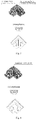
Fig.2 is a sample angle of a welding angle with a weld flash after welding. -
Fig.3 is a sample angle of the welding angle after weld flash removal. -
Fig.4 is an angle clearance-free welding effect of the welding angle after the welding method in the present invention is adopted. -
Fig.5 is a perspective diagram of a section bar to be processed. -
Fig.6 is a 45° sectional view of the section bar to be processed; and a part marked by an oblique line is an outer contour 7. -
Fig.7 is a schematic diagram of a structure of a double-head saw in the embodiment. -
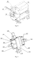
Fig.8 is a schematic diagram of a structure of a movable saw head of the double-head saw in the embodiment. -
Fig.9 is a schematic diagram of a structure of a processing center in the double-head saw in the embodiment. -
Fig.10 is another schematic diagram of a structure of the processing center in the double-head saw in the embodiment. -
Fig.11 is a schematic diagram of angle change of a saw head in the embodiment. - In the
figures: 1 . lathe bed; 2. fixed saw head; 3. movable saw head; 4. electric box; 5. operation box; 6. computer control console; 7. outer contour of section bar; 31. saw cutting center; 32. processing center; 33. locating and clamping mould; 34. section bar; 3201. X direction bottom plate; 3202. X direction servo motor and feed screw nut; 3203. X direction guide rail and slide block; 3204. Y direction bottom plate; 3205. Y direction guide rail and slide block; 3206. Y direction servo motor and feed screw nut; 3207. Z direction bottom plate; 3208. Z direction servo motor and feed screw nut; 3209. Z direction guide rail and slide block; 3210. sliding plate; 3211. power head and cutter. - The present invention will be further illustrated below in combination with the accompanying drawings and specific embodiments.
- The embodiment discloses an angle clearance-free welding method for processing a seamless welding angle as shown in
Fig.4 . The angle clearance-free welding method for uPVC doors and windows is used for welding the welding angle formed by assembly of a left side welding unit and a right side welding unit; wherein opposite assembly inner side faces of the left side welding unit and the right side welding unit are cut surfaces; before the left side welding unit and the right side welding unit are welded, the outer surface of the outer contour of each of the cut surfaces needs to be milled off inward by using a cutting saw for a width of 1-4mm and a depth of 1.5-3mm to form a groove on the outer surface of the outer contour, so that a material fused by welding of the cut surfaces in a welding process does not overflow to the surface and is retained in the groove, therefore no weld flash is formed on the surface, and the appearance quality is good. - The embodiment further discloses a double-head cutting saw (as shown in
Fig.5 to Fig.8 ) with an automatic processing function in the above process for cutting the section bar. The double-head cutting saw includes a lathe bed 1, a fixed saw head 2, a movable saw head 3, an electric box 4, an operation box 5 and a computer control console 6; the fixed saw head 2 is fixed at one end of the lathe bed 1, and the movable saw head 3 moves along a slide rail on the lathe bed 1; the computer control console 6 is connected with the operation box 5; the operation box 5 is connected with the electric box 4; the movement of the fixed saw head 2 and the movable saw head 3 is controlled by the electric box 4; the movable saw head 3 includes asaw cutting center 31, aprocessing center 32, a locating and clampingmould 33 and a worktable; the locating and clampingmould 33 clamps and fixes asection bar 34 needing to be processed on the worktable, and thesaw cutting center 31 horizontally saws and cuts the end face of the section bar; and theprocessing center 32 mills the outer contour of the cut end face of the section bar. - In the embodiment, the
processing center 32 is arranged in each of the fixed saw head 2 and the movable saw head 3; theprocessing center 32 includes an X directionbottom plate 3201, an X direction servo motor and feedscrew nut 3202, an X direction guide rail andslide block 3203, a Y directionbottom plate 3204, a Y direction guide rail andslide block 3205, a Y direction servo motor and feedscrew nut 3206, a Z directionbottom plate 3207, a Z direction servo motor and feedscrew nut 3208, a Z direction guide rail andslide block 3209, a slidingplate 3210 and a power head andcutter 3211. - The connection relationship of the above components is as follows: the power head and
cutter 3211 is installed on the slidingplate 3210; the X direction guide rail andslide block 3203 is installed on the X directionbottom plate 3201; the X direction servo motor and feedscrew nut 3202 drives the slidingplate 3210 to move in an X direction under the guide of the X direction guide rail andslide block 3203; the Y directionbottom plate 3204 is installed under the X directionbottom plate 3201; the Y direction guide rail andslide block 3205 is installed on the Y directionbottom plate 3204; the Y direction servo motor and feedscrew nut 3206 drives the slidingplate 3210 to move in a Y direction under the guide of the Y direction guide rail andslide block 3205; the Z directionbottom plate 3207 is installed on the side face of the Y directionbottom plate 3204; the Z direction guide rail andslide block 3209 is installed on the Z directionbottom plate 3207; and the Z direction servo motor and feedscrew nut 3208 drives the slidingplate 3210 to move in a Z direction under the guide of the Z direction guide rail andslide block 3209. - The working process of the double-head cutting saw in the embodiment is as follows: the movable saw head 3 moves to a corresponding position of the lathe bed 1 according to a required length, then the locating and clamping
mould 33 in the fixed saw head 2 and the movable saw head 3 presses and locates the section bar to be processed on the worktable, thesaw cutting center 31 cuts the end face of the section bar according to cutting requirements of the end face of the section bar, theprocessing center 32 mills the outer contour of the section bar according to outer contour data of the section bar calculated by the computer control console 6, and theprocessing center 32 guarantees whole-space accurate processing of the outer contour at various angles in various direction via three-axis linkage. - A processing method of the double-head cutting saw with the automatic processing function for processing the outer contour of the section bar includes the following steps:
- (1) inputting a sectional view of a section bar to be cut into the control device, actively extracting the outer contour of the section bar to be cut through a computing center in the control device, and generating an outer contour processing procedure of the double-head cutting saw;
- (2) starting the double-head cutting saw for saw cutting, and locating and pressing the section bar on the worktable through the locating and clamping mould in the double-head cutting saw, wherein the entire cutting off, saw cutting and end face milling process of the section bar is located at a pressed state;
- (3) cutting: using the saw cutting center to cut the section bar into a section bar conforming to a required length, then removing scrap materials dropping in the cutting process of the section bar and the remaining uncut material having entire segments, only retaining the section bar conforming to the length requirement and having an end face to be further processed, and leaving a corresponding space for the participation of the processing center for subsequent processing;
- (4) cutting the outer contour of the end face: driving the power head and cutter in the processing center to move along the outer contour line of the section bar by means of the servo motors and the feed screw nuts to mill the outer contour of the end face;
- (6) loosening the locating and clamping mould after cutting the outer contour of the end face, and taking out the material; and
- (7) feeding the material again, and repeating the above process.
Claims (5)
- An angle clearance-free welding method for uPVC doors and windows, wherein the method is used for welding a welding angle formed by assembly of a left side welding unit and a right side welding unit; opposite assembly inner side faces of the left side welding unit and the right side welding unit are cut surfaces; before the left side welding unit and the right side welding unit are welded, the outer surface of the outer contour of the cut surface needs to be milled off inward by using a cutting saw for a width of 1-4mm and a depth of 1.5-3mm to form a groove on the outer surface of the outer contour, so that a material fused by welding of the cut surface in a welding process does not overflow to the surface and is retained in the groove.
- A double-head cutting saw with an automatic processing function, which is applied to the angle clearance-free welding method for uPVC doors and windows of claim 1, comprising a fixed saw head (2) and a movable saw head (3), wherein processing centers (32) are arranged in both of the fixed saw head (2) and the movable saw head (3);
the processing center (32) comprises an X direction bottom plate (3201), an X direction servo motor and feed screw nut (3202), an X direction guide rail and slide block (3203), a Y direction bottom plate (3204), a Y direction guide rail and slide block (3205), a Y direction servo motor and feed screw nut (3206), a Z direction bottom plate (3207), a Z direction servo motor and feed screw nut (3208), a Z direction guide rail and slide block (3209), a sliding plate (3210) and a power head and cutter (3211);
the power head and cutter (3211) is installed on the sliding plate (3210); the X direction guide rail and slide block (3203) is installed on the X direction bottom plate (3201); the X direction servo motor and feed screw nut (3202) drives the sliding plate (3210) to move in an X direction under the guide of the X direction guide rail and slide block (3203);
the Y direction bottom plate (3204) is installed under the X direction bottom plate (3201); the Y direction guide rail and slide block (3205) is installed on the Y direction bottom plate (3204); the Y direction servo motor and feed screw nut (3206) drives the sliding plate (3210) to move in a Y direction under the guide of the Y direction guide rail and slide block (3205); and
the Z direction bottom plate (3207) is installed on the side face of the Y direction bottom plate (3204); the Z direction guide rail and slide block (3209) is installed on the Z direction bottom plate (3207); and the Z direction servo motor and feed screw nut (3208) drives the sliding plate (3210) to move in a Z direction under the guide of the Z direction guide rail and slide block (3209). - The double-head cutting saw with the automatic processing function of claim 2, comprising: a lathe bed (1), the fixed saw head (2), the movable saw head (3), an electric box (4) and a control device;
the fixed saw head (2) is fixed at one end of the lathe bed (1), and the movable saw head (3) moves along a slide rail on the lathe bed (1); the control device is connected with the electric box (4), a command sent by the control device is transmitted to the fixed saw head (2) and the movable saw head (3) through the electric box (4) to control the start, stop and movement of the fixed saw head (2) and the movable saw head (3);
each of the fixed saw head (2) and the movable saw head (3) comprises a saw cutting center (31), the processing center (32), a locating and clamping mould (33) and a worktable; the locating and clamping mould (33) clamps and fixes a section bar (34) needing to be processed on the worktable, and the saw cutting center (31) horizontally saws and cuts the end face of the section bar; the processing center (32) mills the outer contour of the cut end face of the section bar; the cutter in the power head and cutter (3211) is perpendicular to a saw blade in the saw cutting center (31), and when cutting at different angles, the cutter is consistently perpendicular to the cut surface. - The double-head cutting saw with the automatic processing function of claim 3, wherein the control device comprises an operation box (5) and/or a computer control console (6).
- A processing method of the double-head cutting saw with the automatic processing function of claim 3, wherein the specific steps of the method are as follows:(1) inputting a sectional view of a section bar to be cut into the control device, actively extracting the outer contour of the section bar to be cut through a computing center in the control device, and generating an outer contour processing procedure of the double-head cutting saw;(2) starting the double-head cutting saw for saw cutting, and locating and pressing the section bar on the worktable through the locating and clamping mould in the double-head cutting saw, wherein the entire cutting off, saw cutting and end face milling process of the section bar is located at a pressed state;(3) cutting: using the saw cutting center to cut the section bar into a section bar conforming to a required length, then removing scrap materials dropping in the cutting process of the section bar and the remaining uncut material having entire segments, only retaining the section bar conforming to the required length and having an end face to be further processed, and leaving a corresponding space for the participation of the processing center for subsequent processing;(4) cutting the outer contour of the end face: driving the power head and cutter in the processing center to move along the outer contour line of the section bar by means of the servo motors and the feed screw nuts to mill the outer contour of the end face;(6) loosening the locating and clamping mould after cutting the outer contour of the end face, and taking out the material; and(7) feeding the material again, and repeating the above process.
Priority Applications (1)
| Application Number | Priority Date | Filing Date | Title |
|---|---|---|---|
| PL16154241T PL3090858T3 (en) | 2015-04-13 | 2016-02-04 | Double-head cutting saw with automatic processing function |
Applications Claiming Priority (1)
| Application Number | Priority Date | Filing Date | Title |
|---|---|---|---|
| CN201510169463.5A CN104786492B (en) | 2015-04-13 | 2015-04-13 | A kind of exempt from clear welded corner joint method and the Double-edged Incising Saw with automatic machining function |
Publications (3)
| Publication Number | Publication Date |
|---|---|
| EP3090858A2 true EP3090858A2 (en) | 2016-11-09 |
| EP3090858A3 EP3090858A3 (en) | 2017-03-15 |
| EP3090858B1 EP3090858B1 (en) | 2018-07-04 |
Family
ID=53551881
Family Applications (1)
| Application Number | Title | Priority Date | Filing Date |
|---|---|---|---|
| EP16154241.0A Active EP3090858B1 (en) | 2015-04-13 | 2016-02-04 | Double-head cutting saw with automatic processing function |
Country Status (4)
| Country | Link |
|---|---|
| EP (1) | EP3090858B1 (en) |
| CN (1) | CN104786492B (en) |
| PL (1) | PL3090858T3 (en) |
| WO (1) | WO2016165450A1 (en) |
Cited By (2)
| Publication number | Priority date | Publication date | Assignee | Title |
|---|---|---|---|---|
| CN110466164A (en) * | 2019-06-27 | 2019-11-19 | 上海浩泽诺瑞空气净化设备有限公司 | A kind of central air-conditioning plastic-steel section bar machine-shaping device and its processing method |
| IT202200007391A1 (en) * | 2022-04-13 | 2023-10-13 | Emmegi Spa | Method, system and tool device for processing profiled bars. |
Families Citing this family (16)
| Publication number | Priority date | Publication date | Assignee | Title |
|---|---|---|---|---|
| CN104786492B (en) * | 2015-04-13 | 2017-03-08 | 太仓威格玛机械设备有限公司 | A kind of exempt from clear welded corner joint method and the Double-edged Incising Saw with automatic machining function |
| CN105414619A (en) * | 2015-12-31 | 2016-03-23 | 无锡华联科技集团有限公司 | Longitudinal joint milling machine for pipe |
| CN106273522B (en) * | 2016-08-11 | 2019-02-05 | 浙江瑞明节能科技股份有限公司 | A kind of aluminium macromolecule veneer composite door and window corner processing method |
| CN108741163A (en) * | 2017-02-05 | 2018-11-06 | 六安永贞匠道机电科技有限公司 | A kind of root excision equipment of crops |
| CN107214378B (en) * | 2017-07-17 | 2018-10-12 | 台州创兴环保科技有限公司 | A kind of double head type die cutting devices |
| CN107520374B (en) * | 2017-09-13 | 2019-07-26 | 福建鼎力电缆科技有限公司 | A kind of efficient double end cable cast-cutting saw |
| CN107671558A (en) * | 2017-09-19 | 2018-02-09 | 佛山锋顺机械科技有限公司 | A kind of double-pole angle cutting machine |
| CN107639842B (en) * | 2017-10-31 | 2023-07-21 | 山东辰禾智能装备有限公司 | Four-corner welding machine head for welding plastic doors and windows and welding method |
| CN107877264A (en) * | 2017-11-29 | 2018-04-06 | 广东海富纳数控科技有限公司 | Bilateral positions cutters |
| CN108312195B (en) * | 2018-02-26 | 2023-05-26 | 蒋丰亮 | Pipeline port rotary cutting machine for PE large-caliber fiber reinforced pipeline |
| CN109434214A (en) * | 2018-12-19 | 2019-03-08 | 鹤山联塑实业发展有限公司 | A kind of process equipment for profile |
| CN112846324B (en) * | 2021-03-08 | 2025-10-14 | 山东乾正数控机械有限公司 | Milling machine head for processing thermal insulation aluminum doors and windows |
| CN113182608B (en) * | 2021-03-31 | 2023-12-15 | 杭州晨龙智能科技有限公司 | Multi-row band sawing machine and cutting method for multi-row band sawing machine |
| CN115890305B (en) * | 2022-11-29 | 2026-05-05 | 济南康宏机械有限公司 | High-precision sawing method for Z-shaped materials |
| CN116571810B (en) * | 2023-07-14 | 2023-11-03 | 山东辰禾智能装备有限公司 | Sawing device and method for profile with drainage slope |
| CN118404345B (en) * | 2024-05-20 | 2024-12-27 | 沧州鹏发管道装备制造有限公司 | A positioning device for welding a pipe support |
Family Cites Families (14)
| Publication number | Priority date | Publication date | Assignee | Title |
|---|---|---|---|---|
| DE3511498C2 (en) * | 1985-03-29 | 1995-06-01 | Bernhard Eisenbach | Device for processing posts or rungs made of plastic or aluminum profile bars for windows or doors |
| JP4855802B2 (en) * | 2006-02-28 | 2012-01-18 | 独立行政法人理化学研究所 | Long shape material processing apparatus and method |
| WO2010133910A1 (en) * | 2009-05-21 | 2010-11-25 | Emmegi S.P.A. | Machine tool |
| CN201745121U (en) * | 2010-06-17 | 2011-02-16 | 安阳市佳明机械有限责任公司 | Plastic door and window cross-shaped corner cleaning machine |
| US20120060662A1 (en) * | 2010-07-07 | 2012-03-15 | Dummow Systems Corporation | Automated stick-frame system |
| EP3156214B1 (en) * | 2012-03-07 | 2018-11-28 | Graf Synergy S.r.L. | Device for welding profiled elements in plastic material, in particular pvc |
| ITMI20130137A1 (en) * | 2013-01-31 | 2014-08-01 | Graf Synergy Srl | METHOD AND DEFINITION EQUIPMENT OF PROFILE PERIMETER FOR TUBULARS |
| CN203356728U (en) * | 2013-04-18 | 2013-12-25 | 太仓威格玛机械设备有限公司 | Dual-head composite angle cutting saw |
| CN203542072U (en) * | 2013-11-07 | 2014-04-16 | 佛山金皇宇机械实业有限公司 | Cutting device and profile processing machine |
| CN103737914B (en) * | 2013-11-11 | 2016-04-06 | 浙江瑞明节能科技股份有限公司 | The welding method that a kind of plastic-steel door and window bight connects |
| CN203610968U (en) * | 2013-12-11 | 2014-05-28 | 河北万林门窗有限公司 | Broken bridge alumium profile sawing machine tool |
| CN204248536U (en) * | 2014-10-23 | 2015-04-08 | 太仓威格玛机械设备有限公司 | Be suitable for the Horizontal double-headed machining center of production line balance |
| CN104786492B (en) * | 2015-04-13 | 2017-03-08 | 太仓威格玛机械设备有限公司 | A kind of exempt from clear welded corner joint method and the Double-edged Incising Saw with automatic machining function |
| CN204622613U (en) * | 2015-04-13 | 2015-09-09 | 太仓威格玛机械设备有限公司 | A kind of Double-edged Incising Saw with automatic machining functions |
-
2015
- 2015-04-13 CN CN201510169463.5A patent/CN104786492B/en active Active
-
2016
- 2016-01-28 WO PCT/CN2016/072486 patent/WO2016165450A1/en not_active Ceased
- 2016-02-04 PL PL16154241T patent/PL3090858T3/en unknown
- 2016-02-04 EP EP16154241.0A patent/EP3090858B1/en active Active
Non-Patent Citations (1)
| Title |
|---|
| None |
Cited By (3)
| Publication number | Priority date | Publication date | Assignee | Title |
|---|---|---|---|---|
| CN110466164A (en) * | 2019-06-27 | 2019-11-19 | 上海浩泽诺瑞空气净化设备有限公司 | A kind of central air-conditioning plastic-steel section bar machine-shaping device and its processing method |
| IT202200007391A1 (en) * | 2022-04-13 | 2023-10-13 | Emmegi Spa | Method, system and tool device for processing profiled bars. |
| EP4261019A1 (en) | 2022-04-13 | 2023-10-18 | Emmegi S.P.A. | Method, plant and tool device for processing profiled bars |
Also Published As
| Publication number | Publication date |
|---|---|
| EP3090858A3 (en) | 2017-03-15 |
| WO2016165450A1 (en) | 2016-10-20 |
| CN104786492A (en) | 2015-07-22 |
| PL3090858T3 (en) | 2019-03-29 |
| CN104786492B (en) | 2017-03-08 |
| EP3090858B1 (en) | 2018-07-04 |
Similar Documents
| Publication | Publication Date | Title |
|---|---|---|
| EP3090858B1 (en) | Double-head cutting saw with automatic processing function | |
| CN219131115U (en) | Sheet metal router and laser cutting machine with void structure | |
| US4765532A (en) | Method of and apparatus for connecting metal strips | |
| CN204053063U (en) | A CNC sheet metal V-groove planer | |
| KR20170038065A (en) | Automatic machining device for high-speed rail pantograph carbon contact strip and machining method therefor | |
| US7159294B2 (en) | Burr removal apparatus for laser beam machine | |
| CN212330569U (en) | Multifunctional machine for slitting V-shaped groove and edging | |
| CN204622613U (en) | A kind of Double-edged Incising Saw with automatic machining functions | |
| WO2019057658A1 (en) | METHOD OF WORKING WORKPIECES, COMPUTER PROGRAM PRODUCT, AND WORKPIECE MACHINING SYSTEM | |
| CN210703814U (en) | Automatic steering machine for cross axle | |
| CN208992162U (en) | Automotive door hinge drilling hole machine tool | |
| CN105252273A (en) | Numeral control planing and shearing machine integrating slot planing and plate shearing | |
| KR102334940B1 (en) | Door and windows welding machine to minimize welding line | |
| CN216370360U (en) | Automatic edge planing mechanism for square plate | |
| KR200200915Y1 (en) | Cutting and boring machine of wood | |
| CN216462955U (en) | Well club angle sign indicating number automatic processing equipment | |
| CN214815152U (en) | A multi-station milling machine | |
| CN219853433U (en) | Blank positioner | |
| CN115401468A (en) | Aluminum alloy door and window machining center | |
| CN222002051U (en) | High efficiency CNC cutting saw | |
| CN209255995U (en) | A kind of double sawframe vertical band sawing machines | |
| CN115476407B (en) | Self-wedge type primary-secondary groove synchronous machining equipment and process | |
| CN106826973A (en) | A kind of guillotine based on 3D rotations | |
| EP1430996B1 (en) | Machining unit for deburring corner joints of frames of welded plastic profiles | |
| CN215788249U (en) | Skin sheet metal precision mills cuts auxiliary device |
Legal Events
| Date | Code | Title | Description |
|---|---|---|---|
| PUAI | Public reference made under article 153(3) epc to a published international application that has entered the european phase |
Free format text: ORIGINAL CODE: 0009012 |
|
| 17P | Request for examination filed |
Effective date: 20160204 |
|
| AK | Designated contracting states |
Kind code of ref document: A2 Designated state(s): AL AT BE BG CH CY CZ DE DK EE ES FI FR GB GR HR HU IE IS IT LI LT LU LV MC MK MT NL NO PL PT RO RS SE SI SK SM TR |
|
| AX | Request for extension of the european patent |
Extension state: BA ME |
|
| REG | Reference to a national code |
Ref country code: DE Ref legal event code: R079 Ref document number: 602016003867 Country of ref document: DE Free format text: PREVIOUS MAIN CLASS: B29C0065020000 Ipc: B23C0003000000 |
|
| PUAL | Search report despatched |
Free format text: ORIGINAL CODE: 0009013 |
|
| AK | Designated contracting states |
Kind code of ref document: A3 Designated state(s): AL AT BE BG CH CY CZ DE DK EE ES FI FR GB GR HR HU IE IS IT LI LT LU LV MC MK MT NL NO PL PT RO RS SE SI SK SM TR |
|
| AX | Request for extension of the european patent |
Extension state: BA ME |
|
| RIC1 | Information provided on ipc code assigned before grant |
Ipc: B23D 45/04 20060101ALI20170203BHEP Ipc: E06B 3/96 20060101ALI20170203BHEP Ipc: B23Q 39/02 20060101ALI20170203BHEP Ipc: B23C 3/12 20060101ALI20170203BHEP Ipc: B23D 45/14 20060101ALI20170203BHEP Ipc: B23C 3/30 20060101ALI20170203BHEP Ipc: B23C 3/00 20060101AFI20170203BHEP Ipc: B29C 65/02 20060101ALI20170203BHEP |
|
| GRAP | Despatch of communication of intention to grant a patent |
Free format text: ORIGINAL CODE: EPIDOSNIGR1 |
|
| STAA | Information on the status of an ep patent application or granted ep patent |
Free format text: STATUS: GRANT OF PATENT IS INTENDED |
|
| INTG | Intention to grant announced |
Effective date: 20180226 |
|
| GRAS | Grant fee paid |
Free format text: ORIGINAL CODE: EPIDOSNIGR3 |
|
| GRAA | (expected) grant |
Free format text: ORIGINAL CODE: 0009210 |
|
| STAA | Information on the status of an ep patent application or granted ep patent |
Free format text: STATUS: THE PATENT HAS BEEN GRANTED |
|
| AK | Designated contracting states |
Kind code of ref document: B1 Designated state(s): AL AT BE BG CH CY CZ DE DK EE ES FI FR GB GR HR HU IE IS IT LI LT LU LV MC MK MT NL NO PL PT RO RS SE SI SK SM TR |
|
| REG | Reference to a national code |
Ref country code: GB Ref legal event code: FG4D |
|
| REG | Reference to a national code |
Ref country code: CH Ref legal event code: EP |
|
| REG | Reference to a national code |
Ref country code: AT Ref legal event code: REF Ref document number: 1013969 Country of ref document: AT Kind code of ref document: T Effective date: 20180715 |
|
| REG | Reference to a national code |
Ref country code: IE Ref legal event code: FG4D |
|
| REG | Reference to a national code |
Ref country code: DE Ref legal event code: R096 Ref document number: 602016003867 Country of ref document: DE |
|
| REG | Reference to a national code |
Ref country code: NL Ref legal event code: MP Effective date: 20180704 |
|
| REG | Reference to a national code |
Ref country code: LT Ref legal event code: MG4D |
|
| REG | Reference to a national code |
Ref country code: AT Ref legal event code: MK05 Ref document number: 1013969 Country of ref document: AT Kind code of ref document: T Effective date: 20180704 |
|
| PG25 | Lapsed in a contracting state [announced via postgrant information from national office to epo] |
Ref country code: NL Free format text: LAPSE BECAUSE OF FAILURE TO SUBMIT A TRANSLATION OF THE DESCRIPTION OR TO PAY THE FEE WITHIN THE PRESCRIBED TIME-LIMIT Effective date: 20180704 |
|
| PG25 | Lapsed in a contracting state [announced via postgrant information from national office to epo] |
Ref country code: FI Free format text: LAPSE BECAUSE OF FAILURE TO SUBMIT A TRANSLATION OF THE DESCRIPTION OR TO PAY THE FEE WITHIN THE PRESCRIBED TIME-LIMIT Effective date: 20180704 Ref country code: AT Free format text: LAPSE BECAUSE OF FAILURE TO SUBMIT A TRANSLATION OF THE DESCRIPTION OR TO PAY THE FEE WITHIN THE PRESCRIBED TIME-LIMIT Effective date: 20180704 Ref country code: IS Free format text: LAPSE BECAUSE OF FAILURE TO SUBMIT A TRANSLATION OF THE DESCRIPTION OR TO PAY THE FEE WITHIN THE PRESCRIBED TIME-LIMIT Effective date: 20181104 Ref country code: GR Free format text: LAPSE BECAUSE OF FAILURE TO SUBMIT A TRANSLATION OF THE DESCRIPTION OR TO PAY THE FEE WITHIN THE PRESCRIBED TIME-LIMIT Effective date: 20181005 Ref country code: RS Free format text: LAPSE BECAUSE OF FAILURE TO SUBMIT A TRANSLATION OF THE DESCRIPTION OR TO PAY THE FEE WITHIN THE PRESCRIBED TIME-LIMIT Effective date: 20180704 Ref country code: NO Free format text: LAPSE BECAUSE OF FAILURE TO SUBMIT A TRANSLATION OF THE DESCRIPTION OR TO PAY THE FEE WITHIN THE PRESCRIBED TIME-LIMIT Effective date: 20181004 Ref country code: SE Free format text: LAPSE BECAUSE OF FAILURE TO SUBMIT A TRANSLATION OF THE DESCRIPTION OR TO PAY THE FEE WITHIN THE PRESCRIBED TIME-LIMIT Effective date: 20180704 Ref country code: CZ Free format text: LAPSE BECAUSE OF FAILURE TO SUBMIT A TRANSLATION OF THE DESCRIPTION OR TO PAY THE FEE WITHIN THE PRESCRIBED TIME-LIMIT Effective date: 20180704 Ref country code: BG Free format text: LAPSE BECAUSE OF FAILURE TO SUBMIT A TRANSLATION OF THE DESCRIPTION OR TO PAY THE FEE WITHIN THE PRESCRIBED TIME-LIMIT Effective date: 20181004 Ref country code: LT Free format text: LAPSE BECAUSE OF FAILURE TO SUBMIT A TRANSLATION OF THE DESCRIPTION OR TO PAY THE FEE WITHIN THE PRESCRIBED TIME-LIMIT Effective date: 20180704 |
|
| PG25 | Lapsed in a contracting state [announced via postgrant information from national office to epo] |
Ref country code: HR Free format text: LAPSE BECAUSE OF FAILURE TO SUBMIT A TRANSLATION OF THE DESCRIPTION OR TO PAY THE FEE WITHIN THE PRESCRIBED TIME-LIMIT Effective date: 20180704 Ref country code: LV Free format text: LAPSE BECAUSE OF FAILURE TO SUBMIT A TRANSLATION OF THE DESCRIPTION OR TO PAY THE FEE WITHIN THE PRESCRIBED TIME-LIMIT Effective date: 20180704 Ref country code: AL Free format text: LAPSE BECAUSE OF FAILURE TO SUBMIT A TRANSLATION OF THE DESCRIPTION OR TO PAY THE FEE WITHIN THE PRESCRIBED TIME-LIMIT Effective date: 20180704 Ref country code: ES Free format text: LAPSE BECAUSE OF FAILURE TO SUBMIT A TRANSLATION OF THE DESCRIPTION OR TO PAY THE FEE WITHIN THE PRESCRIBED TIME-LIMIT Effective date: 20180704 |
|
| REG | Reference to a national code |
Ref country code: DE Ref legal event code: R097 Ref document number: 602016003867 Country of ref document: DE |
|
| PG25 | Lapsed in a contracting state [announced via postgrant information from national office to epo] |
Ref country code: RO Free format text: LAPSE BECAUSE OF FAILURE TO SUBMIT A TRANSLATION OF THE DESCRIPTION OR TO PAY THE FEE WITHIN THE PRESCRIBED TIME-LIMIT Effective date: 20180704 Ref country code: EE Free format text: LAPSE BECAUSE OF FAILURE TO SUBMIT A TRANSLATION OF THE DESCRIPTION OR TO PAY THE FEE WITHIN THE PRESCRIBED TIME-LIMIT Effective date: 20180704 Ref country code: IT Free format text: LAPSE BECAUSE OF FAILURE TO SUBMIT A TRANSLATION OF THE DESCRIPTION OR TO PAY THE FEE WITHIN THE PRESCRIBED TIME-LIMIT Effective date: 20180704 |
|
| PLBE | No opposition filed within time limit |
Free format text: ORIGINAL CODE: 0009261 |
|
| STAA | Information on the status of an ep patent application or granted ep patent |
Free format text: STATUS: NO OPPOSITION FILED WITHIN TIME LIMIT |
|
| PG25 | Lapsed in a contracting state [announced via postgrant information from national office to epo] |
Ref country code: SM Free format text: LAPSE BECAUSE OF FAILURE TO SUBMIT A TRANSLATION OF THE DESCRIPTION OR TO PAY THE FEE WITHIN THE PRESCRIBED TIME-LIMIT Effective date: 20180704 Ref country code: DK Free format text: LAPSE BECAUSE OF FAILURE TO SUBMIT A TRANSLATION OF THE DESCRIPTION OR TO PAY THE FEE WITHIN THE PRESCRIBED TIME-LIMIT Effective date: 20180704 Ref country code: SK Free format text: LAPSE BECAUSE OF FAILURE TO SUBMIT A TRANSLATION OF THE DESCRIPTION OR TO PAY THE FEE WITHIN THE PRESCRIBED TIME-LIMIT Effective date: 20180704 |
|
| 26N | No opposition filed |
Effective date: 20190405 |
|
| PG25 | Lapsed in a contracting state [announced via postgrant information from national office to epo] |
Ref country code: SI Free format text: LAPSE BECAUSE OF FAILURE TO SUBMIT A TRANSLATION OF THE DESCRIPTION OR TO PAY THE FEE WITHIN THE PRESCRIBED TIME-LIMIT Effective date: 20180704 |
|
| REG | Reference to a national code |
Ref country code: CH Ref legal event code: PL |
|
| PG25 | Lapsed in a contracting state [announced via postgrant information from national office to epo] |
Ref country code: LU Free format text: LAPSE BECAUSE OF NON-PAYMENT OF DUE FEES Effective date: 20190204 Ref country code: MC Free format text: LAPSE BECAUSE OF FAILURE TO SUBMIT A TRANSLATION OF THE DESCRIPTION OR TO PAY THE FEE WITHIN THE PRESCRIBED TIME-LIMIT Effective date: 20180704 |
|
| REG | Reference to a national code |
Ref country code: BE Ref legal event code: MM Effective date: 20190228 |
|
| REG | Reference to a national code |
Ref country code: IE Ref legal event code: MM4A |
|
| PG25 | Lapsed in a contracting state [announced via postgrant information from national office to epo] |
Ref country code: CH Free format text: LAPSE BECAUSE OF NON-PAYMENT OF DUE FEES Effective date: 20190228 Ref country code: LI Free format text: LAPSE BECAUSE OF NON-PAYMENT OF DUE FEES Effective date: 20190228 |
|
| PG25 | Lapsed in a contracting state [announced via postgrant information from national office to epo] |
Ref country code: IE Free format text: LAPSE BECAUSE OF NON-PAYMENT OF DUE FEES Effective date: 20190204 |
|
| PG25 | Lapsed in a contracting state [announced via postgrant information from national office to epo] |
Ref country code: BE Free format text: LAPSE BECAUSE OF NON-PAYMENT OF DUE FEES Effective date: 20190228 Ref country code: FR Free format text: LAPSE BECAUSE OF NON-PAYMENT OF DUE FEES Effective date: 20190228 |
|
| PG25 | Lapsed in a contracting state [announced via postgrant information from national office to epo] |
Ref country code: TR Free format text: LAPSE BECAUSE OF FAILURE TO SUBMIT A TRANSLATION OF THE DESCRIPTION OR TO PAY THE FEE WITHIN THE PRESCRIBED TIME-LIMIT Effective date: 20180704 |
|
| PG25 | Lapsed in a contracting state [announced via postgrant information from national office to epo] |
Ref country code: PT Free format text: LAPSE BECAUSE OF FAILURE TO SUBMIT A TRANSLATION OF THE DESCRIPTION OR TO PAY THE FEE WITHIN THE PRESCRIBED TIME-LIMIT Effective date: 20181104 Ref country code: MT Free format text: LAPSE BECAUSE OF NON-PAYMENT OF DUE FEES Effective date: 20190204 |
|
| PG25 | Lapsed in a contracting state [announced via postgrant information from national office to epo] |
Ref country code: CY Free format text: LAPSE BECAUSE OF FAILURE TO SUBMIT A TRANSLATION OF THE DESCRIPTION OR TO PAY THE FEE WITHIN THE PRESCRIBED TIME-LIMIT Effective date: 20180704 |
|
| PG25 | Lapsed in a contracting state [announced via postgrant information from national office to epo] |
Ref country code: HU Free format text: LAPSE BECAUSE OF FAILURE TO SUBMIT A TRANSLATION OF THE DESCRIPTION OR TO PAY THE FEE WITHIN THE PRESCRIBED TIME-LIMIT; INVALID AB INITIO Effective date: 20160204 |
|
| PG25 | Lapsed in a contracting state [announced via postgrant information from national office to epo] |
Ref country code: MK Free format text: LAPSE BECAUSE OF FAILURE TO SUBMIT A TRANSLATION OF THE DESCRIPTION OR TO PAY THE FEE WITHIN THE PRESCRIBED TIME-LIMIT Effective date: 20180704 |
|
| PGFP | Annual fee paid to national office [announced via postgrant information from national office to epo] |
Ref country code: GB Payment date: 20260219 Year of fee payment: 11 |
|
| PGFP | Annual fee paid to national office [announced via postgrant information from national office to epo] |
Ref country code: DE Payment date: 20260206 Year of fee payment: 11 |
|
| PGFP | Annual fee paid to national office [announced via postgrant information from national office to epo] |
Ref country code: PL Payment date: 20260119 Year of fee payment: 11 |