CN115401468A - Aluminum alloy door and window machining center - Google Patents
Aluminum alloy door and window machining center Download PDFInfo
- Publication number
- CN115401468A CN115401468A CN202211365000.2A CN202211365000A CN115401468A CN 115401468 A CN115401468 A CN 115401468A CN 202211365000 A CN202211365000 A CN 202211365000A CN 115401468 A CN115401468 A CN 115401468A
- Authority
- CN
- China
- Prior art keywords
- cutting
- laser
- saw blade
- machining center
- alloy door
- Prior art date
- Legal status (The legal status is an assumption and is not a legal conclusion. Google has not performed a legal analysis and makes no representation as to the accuracy of the status listed.)
- Pending
Links
Images


Classifications
-
- B—PERFORMING OPERATIONS; TRANSPORTING
- B23—MACHINE TOOLS; METAL-WORKING NOT OTHERWISE PROVIDED FOR
- B23P—METAL-WORKING NOT OTHERWISE PROVIDED FOR; COMBINED OPERATIONS; UNIVERSAL MACHINE TOOLS
- B23P23/00—Machines or arrangements of machines for performing specified combinations of different metal-working operations not covered by a single other subclass
- B23P23/04—Machines or arrangements of machines for performing specified combinations of different metal-working operations not covered by a single other subclass for both machining and other metal-working operations
Landscapes
- Physics & Mathematics (AREA)
- Optics & Photonics (AREA)
- Engineering & Computer Science (AREA)
- Mechanical Engineering (AREA)
- Laser Beam Processing (AREA)
Abstract
The invention provides an aluminum alloy door and window machining center which comprises a feeding mechanism, a laser scribing and cutting mechanism and a discharging mechanism which are sequentially arranged, wherein the laser scribing and cutting mechanism comprises a base, a scribing device and a cutting device, the scribing device is arranged on the base and close to the feeding mechanism, and the cutting device is arranged on the base and close to the discharging mechanism. The laser scribing and cutting device integrates two independent operating devices, namely laser scribing and laser cutting, into one device, so that the laser scribing and cutting device has the functions of simplifying the structure and saving the space, and also perfectly integrates all functions of a plurality of independent parts in function; in efficiency, due to the fact that the existing laser scribing technology can realize carving on a moving object, the carving can be directly carried out during section material loading without independent time, namely the time required by laser scribing is contained in the loading time, extra time for scribing is not needed, and further the processing efficiency is improved; the holes of various patterns are cut by laser without tool changing, the feeding speed is high, and the processing efficiency is further improved.
Description
Technical Field
The invention relates to the technical field of aluminum alloy door and window processing equipment, in particular to an aluminum alloy door and window processing center.
Background
Along with the diversification of the section and the window size and the style of the aluminum alloy door and window assembly section and the development of the home decoration industry, the individuation and the quality requirements of the door and the window are higher and higher, and the precision requirements of the window and the technical requirements of technical workers are also improved. And along with the more and more high labour cost and trade concentration, original unit processing mode, because this kind of mode is higher to technical worker's skill requirement, if workman's skill can not reach the requirement, its production efficiency and door and window quality all can not obtain effectual guarantee, and its administrative cost and comprehensive cost are all higher. Therefore, the processing mode is not suitable for the processing production of modern aluminum alloy doors and windows.
In addition, in the application of an automatic assembly line in the door and window industry, the working procedures are usually split as much as possible, so that the cutting, laser scribing and milling of the section are usually independent parts, the length of the assembly line is prolonged, the production cost is high, the logic relationship is complex, and the distribution is difficult.
Disclosure of Invention
The invention provides an aluminum alloy door and window machining center, which aims at the problems that in the existing door and window production, the cutting, laser scribing and milling of sectional materials are independent to each other, so that the production line is too long, and the like.
The invention provides an aluminum alloy door and window machining center which comprises a feeding mechanism, a laser scribing and cutting mechanism and a discharging mechanism which are sequentially arranged, wherein the laser scribing and cutting mechanism comprises a base, a scribing device and a cutting device, the scribing device is arranged on the base and close to the feeding mechanism, and the cutting device is arranged on the base and close to the discharging mechanism.
Preferably, the groove device includes mounting panel and laser assembly, the mounting panel set up in the up end of base just the through-hole has been seted up at the middle part of mounting panel, the bottom of through-hole is provided with table surface, the mounting panel orientation cutting device's side is provided with laser assembly, laser assembly can pass through at the section bar warp feed mechanism passes through the through-hole moves extremely carry out laser groove or cutting to the section bar behind the table surface.
Preferably, laser subassembly includes slide, first laser head, second laser head and first slip subassembly, first laser head with the second laser head is located respectively the both ends of slide, the slide passes through first slip subassembly slide set up in the mounting panel, the slide can drive first laser head with the second laser head is in the both sides up-and-down motion of through-hole.
Preferably, the laser assembly further comprises a second sliding assembly, and the second laser head is slidably connected with the sliding plate through the second sliding assembly, so that the second laser head can horizontally move along the sliding plate.
Preferably, first slip subassembly includes driving piece, lead screw, nut, linear guide and slider, linear guide is fixed in the mounting panel, one side of slider with linear guide sliding connection, the opposite side with the slide is fixed, the nut rotate set up in the lead screw just the nut is fixed in the slide, the driving piece is fixed in the mounting panel, the drive end of driving piece with the tip fixed connection of lead screw, the driving piece can drive the lead screw rotates, so that the nut drives the slide is followed linear guide up-and-down motion.
Preferably, the mounting panel orientation cutting device's side is provided with the side direction setting element, the side direction setting element is located the through-hole is provided with one side of second laser head, just the side direction setting element set up in table surface's top.
Preferably, the cutting device includes second cutting saw bit, third cutting saw bit and the first cutting saw bit that sets gradually by height on the base, first cutting saw bit can up-and-down motion, the third cutting saw bit can horizontal motion, the cutting edge direction of first cutting saw bit with the cutting edge direction of second cutting saw bit mutually perpendicular and both all are 45 degrees with vertical plane in the horizontal plane, the cutting edge direction of third cutting saw bit with the cutting edge direction of first cutting saw bit, the cutting edge direction of second cutting saw bit all is 45 degrees in the horizontal plane.
Preferably, the cutting device further comprises a lifting assembly, the lifting assembly comprises a stand column, a screw and nut mechanism, a linear guide rail pair and a motor, the stand column is fixed on the base, the linear guide rail pair is arranged on the stand column, the motor is fixed on the stand column, the screw and nut mechanism is connected with the first cutting saw blade, and the motor can drive the screw and nut mechanism to enable the first cutting saw blade to move up and down along the linear guide rail pair.
Preferably, feed mechanism includes feed frame and feeding manipulator, feeding manipulator includes mechanical tongs, link mechanism, cylinder and finger bedplate, mechanical tongs articulate in the finger bedplate, mechanical tongs with link mechanism connects, the cylinder can drive link mechanism drives mechanical tongs with the laminating of finger bedplate or keep away from.
Preferably, the scribing device is one of a single electric spindle mechanism, a front and rear double electric spindle mechanism or an upper and lower double electric spindle mechanism.
Preferably, the discharging mechanism comprises a discharging rack and a labeling machine, and the labeling machine is slidably arranged on the discharging rack.
The invention has the beneficial effects that:
the laser scribing and cutting device integrates two independent operating devices, namely a plurality of independent devices are masoned together on the space structure layout, so that the laser scribing and cutting device plays the roles of simplifying the structure and saving the space, and also perfectly integrates all functions of a plurality of independent parts on the function; in efficiency, the carving on a moving object can be realized due to the existing laser scribing technology, the carving can be directly carried out during the section bar loading without independent time, namely, the time required by laser scribing is included in the loading time, and extra time for scribing is not required, so that the processing efficiency is improved; the holes of various patterns are cut by laser without tool changing, the feeding speed is high, and the processing efficiency is further improved.
Drawings
In order to more clearly illustrate the technical solution of the present invention, the drawings used in the description will be briefly introduced, and it is obvious that the drawings in the following description are only some embodiments of the present invention, and it is obvious for those skilled in the art that other drawings can be obtained based on these drawings without creative efforts.
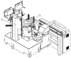
FIG. 1 is a schematic perspective view of a portion of the aluminum alloy door/window machining center according to the present invention.
Fig. 2 is a schematic perspective view of the laser scribing and cutting mechanism according to the present invention.
Fig. 3 is an enlarged view of a portion a in fig. 2.
Fig. 4 is a schematic perspective view of the cutting device according to the present invention.
Fig. 5 is a schematic perspective view of a feeding manipulator according to the present invention.
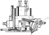
Fig. 6 is a schematic structural diagram of the single electric spindle mechanism according to the present invention.
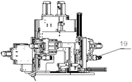
Fig. 7 is a schematic structural diagram of a single electric spindle mechanism with another angle according to the present invention.
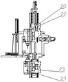
Fig. 8 is a schematic structural diagram of the upper and lower dual electric spindle mechanisms according to the present invention.
Fig. 9 is a schematic structural diagram of the front and rear dual electric spindle mechanisms according to the present invention.
In the figure: 1. the cutting device comprises a feeding mechanism, 2, a discharging mechanism, 3, a base, 4, a scribing device, 5, a cutting device, 6, a mechanical gripper, 7, a link mechanism, 8, a cylinder, 9, a finger seat plate, 10, a mounting plate, 11, a through hole, 12, a workbench surface, 13, a sliding plate, 14, a first laser head, 15, a second laser head, 16, a lateral positioning piece, 17, a driving piece, 18, an electric spindle, 19, a laser cutting head, 20, an upper electric spindle, 21, a lower electric spindle, 22, an upper electric spindle mounting plate, 23, a lower electric spindle mounting plate, 24, a right electric spindle, 25, a left electric spindle, 26, a right electric spindle mounting plate, 27, a left electric spindle mounting plate, 28, a sliding rail seat plate, 29, a second cutting saw blade, 30, a third cutting saw blade, 31, a first cutting saw blade, 32 and a stand column.
Detailed Description
In order to make the objects, features and advantages of the present invention more obvious and understandable, the technical solutions of the present invention will be clearly and completely described below with reference to the accompanying drawings in the present embodiment, and it is obvious that the embodiments described below are only a part of embodiments of the present invention, and not all embodiments. All other embodiments, which can be derived by a person skilled in the art from the embodiments in this patent without making creative efforts, shall fall within the protection scope of this patent.
As shown in fig. 1 to 9, in the embodiment, the invention provides an aluminum alloy door and window machining center, which includes a feeding mechanism 1, a laser scribing and cutting mechanism, and a discharging mechanism 2, which are sequentially arranged, the laser scribing and cutting mechanism includes a base 3, a scribing device 4, and a cutting device 5, the scribing device 4 is arranged on the base 3 and close to the feeding mechanism 1, and the cutting device 5 is arranged on the base 3 and close to the discharging mechanism 2. According to the invention, the scribing device 4 and the cutting device 5 are integrated on the base 3, the feeding end of the scribing device 4 is provided with the feeding mechanism 1, and the discharging end of the cutting device 5 is provided with the discharging mechanism 2, so that scribing, cutting and marking are realized in the workpiece conveying process, the processing efficiency is greatly improved, and the labor intensity of workers is reduced.
Wherein, as shown in fig. 1, 5, feed mechanism includes feed frame and feeding manipulator, and feeding manipulator includes mechanical tongs 6, link mechanism 7, cylinder 8 and finger bedplate 9, and mechanical tongs 6 articulates in finger bedplate 9, and mechanical tongs 6 is connected with link mechanism 7, and cylinder 8 can drive link mechanism 7 and drive mechanical tongs 6 and point bedplate 9 laminating or keep away from. The main function of the feeding mechanism is that the aluminum profile is clamped to enter a working area along the feeding frame. The mechanical gripper 6 is attached to the finger seat plate 9 through the action of the cylinder 8 and the conduction of the connecting rod mechanism 7 so as to grip the aluminum profile, and in order to prevent the aluminum profile from loosening, a serrated tooth form is designed at the tail end of the mechanical gripper 6 so as to ensure that the mechanical gripper 6 can hold the aluminum profile tightly. The connecting rod mechanism 7, the rotating shaft and the part for clamping the aluminum profile are subjected to quenching and tempering, so that the precision and the service life of the feeding manipulator are greatly enhanced, and the requirements on installation and debugging are higher.
Specifically, the material loading manipulator is installed on a long frame with the length of 9 m, and the long frame is installed on an installation plate provided with two servo motors and a lead screw drive, so that the material loading manipulator can clamp different sectional materials. When the aluminum profile is placed on the conveying belt manually or by a robot, the synchronous belt driven by the servo motor drives the aluminum profile to be sent to the direction of the feeding mechanical arm, and the feeding mechanical arm sends the aluminum profile to an area to be processed to wait for processing through the guide and positioning rollers.
As shown in fig. 3, the scribing device includes mounting panel 10 and laser assembly, mounting panel 10 is the L template, mounting panel 10 sets up and has seted up through-hole 11 in the middle part of the up end of base 3 and mounting panel 10, the aluminium alloy carries out the material loading through this through-hole 11, the bottom of through-hole 11 is provided with table surface 12, mounting panel 10 is provided with laser assembly towards cutting device 5's side, laser assembly can carry out laser scribing or cutting to the section bar after section bar through feed mechanism 1 passes through-hole 11 and moves to table surface 12. Specifically, laser subassembly includes slide 13, first laser head 14, second laser head 15 and first slip subassembly, and first laser head 14 and second laser head 15 are located the both ends of slide 13 respectively, and slide 13 sets up in mounting panel 10 through first slip subassembly slip, and slide 13 can drive first laser head 14 and second laser head 15 in the both sides up-and-down motion of through-hole 11, the groove and the cutting of adaptable various not co-altitude or width section bar. The first laser head 14 is fixed on the sliding plate, the second laser head 15 is connected with the sliding plate 13 in a sliding mode through the second sliding assembly, so that the second laser head 15 can move horizontally along the sliding plate 13, a lateral positioning piece 16 is arranged on the side, facing the cutting device 5, of the mounting plate 10, the lateral positioning piece 16 is located on one side, provided with the second laser head 15, of the through hole 11, and the lateral positioning piece 16 is arranged above the working table top 12. Because the table top 12 is provided with the lateral positioning piece 16, only one movable laser head (the second laser head 15) can deal with the focusing problem of various profiles, and the other fixed laser head (the first laser head 14) does not need to move because the distance facing the profiles is fixed, thereby simplifying the structure and saving the space.
Specifically, first slip subassembly includes driving piece 17, the lead screw, the nut, linear guide and slider, linear guide is fixed in mounting panel 10, one side and linear guide sliding connection of slider, the opposite side is fixed with the slide, the nut rotates and sets up and be fixed in slide 13 in lead screw and nut, driving piece 17 is fixed in mounting panel 10, the drive end of driving piece 17 and the tip fixed connection of lead screw, driving piece 17 can drive the lead screw and rotate, so that the nut drives slide 13 along linear guide up-and-down motion, driving piece 17 can set up to servo motor. The second sliding component can also be a screw nut structure driven by a servo motor, and therefore, the details are not repeated herein.
In addition to the above structure, as shown in fig. 6 to 9, the reticle device may be configured as one of a single electric spindle mechanism, a front and rear double electric spindle mechanism, or an upper and lower double electric spindle mechanism according to actual production requirements.
As shown in fig. 6 and 7, the electric spindle 18 changes its machining angle mainly by the expansion and contraction of the air cylinder, and ensures the machining position accuracy of the specific hole of the aluminum profile by the guide rails in the Y direction and the Z direction. The laser cutting head 19 also guarantees the precision of the processing position of the specific hole of the aluminum profile through the Y-direction guide rail and the Z-direction guide rail, does not need to change a tool rest, has high feeding speed and improves the processing efficiency.
As shown in fig. 8, the upper and lower dual electric spindle mechanisms are shown, the upper electric spindle 20 and the lower electric spindle 21 are mounted on the upper electric spindle mounting plate 22 and the lower electric spindle mounting plate 23, the upper electric spindle 20 and the lower electric spindle 21 can slide up and down on the mounting plates through the rail sliders, and then special holes are machined in the aluminum profiles.
As shown in fig. 9, the front and rear dual electric spindle mechanisms are configured such that a right electric spindle 24 and a left electric spindle 25 are mounted on a right electric spindle mounting plate 26 and a left electric spindle mounting plate 27, and the machining positions are adjusted by moving up and down by a slide rail seat plate 28.
As shown in fig. 4, the cutting device includes the second cutting saw blade 29 that sets gradually by height to low on base 3, third cutting saw blade 30 and first cutting saw blade 31, first cutting saw blade 31 can the up-and-down motion, third cutting saw blade 30 can the horizontal motion, the cutting edge direction of first cutting saw blade 31 and the cutting edge direction of second cutting saw blade 29 are mutually perpendicular and both all are 45 degrees with vertical plane in the horizontal plane, the cutting edge direction of third cutting saw blade 30 and the cutting edge direction of first cutting saw blade 31, the cutting edge direction of second cutting saw blade 29 all is 45 degrees in the horizontal plane, the setting direction of three cutting saw blade can adapt to different modes of compressing tightly in the aluminium alloy course of working and lead to the opposite 45 degrees angle switching-over problems that arouse of direction are put to the section bar. Specifically, the up-and-down movement of the first cutting blade 31 is realized by a lifting assembly, the lifting assembly includes an upright column 32, a screw nut mechanism, a linear guide pair and a motor, the upright column 32 is fixed to the base 3, the linear guide pair is disposed on the upright column 32, the motor is fixed to the upright column 32, the screw nut mechanism is connected to the first cutting blade 31, and the motor can drive the screw nut mechanism to move the first cutting blade 31 up and down along the linear guide pair. The horizontal movement of the third cutting blade 30 is implemented substantially similar to the structure of the elevation assembly, and thus, the detailed description thereof is omitted.
As shown in fig. 1, the discharging mechanism includes a discharging rack and a labeling machine for labeling, and the labeling machine is slidably disposed on the discharging rack. When the aluminium alloy sent the aluminium alloy to treat the processing region through the robot tongs, hug tight mechanism and push down the aluminium alloy and send the aluminium alloy to the processing region through the roller, the processing region firmly fixes the section bar on the workstation backup plate through last compress tightly and side compression waits the processing of saw bit. The mid portion of base 3 is equipped with blanking mouth, and the aluminium alloy waste material that cuts off falls to collection device through this mouth in, and the section bar that has finished is then transported out the work or material rest through ejection of compact splint.
After the aluminum profile is processed, the aluminum profile is sent out by a conveyor belt on the labeling rack, and when the aluminum profile reaches a specified position, a movable labeling machine is used for labeling. The function of the labeling machine is to utilize a vacuum loop on the paper suction soft plate to suck the label on the labeling machine and then to adhere the label to the section bar which is already in place through the action of the air cylinder, thus completing the whole processing process.
If a water drain hole, a mounting hole, a glue injection hole or various lock holes need to be machined in the process of cutting off the aluminum profile, an additional process and corresponding machining equipment need to be added, and the machining process can be continuously changed due to different requirements of aluminum profiles with different specifications and models on the positions of various holes. The laser scribing or laser cutting is added in the sawing process, so that the pressure of the subsequent process can be greatly reduced, particularly, the laser scribing can be carved even in the section transportation process, the work which is finished by the scribing machine is finished on the premise of not influencing the work of the machine, and the laser scribing machine has great practical significance.
The beneficial effects of the invention are as follows through the embodiment:
the laser scribing and cutting device integrates two independent operating devices, namely a plurality of independent devices are masoned together on the space structure layout, so that the laser scribing and cutting device plays the roles of simplifying the structure and saving the space, and also perfectly integrates all functions of a plurality of independent parts on the function; in efficiency, due to the fact that the existing laser scribing technology can realize carving on a moving object, the carving can be directly carried out during section material loading without independent time, namely the time required by laser scribing is contained in the loading time, extra time for scribing is not needed, and further the processing efficiency is improved; the holes of various patterns are cut by laser without tool changing, the feeding speed is high, and the processing efficiency is further improved.
The previous description of the disclosed embodiments is provided to enable any person skilled in the art to make or use the present invention. Various modifications to these embodiments will be readily apparent to those skilled in the art, and the generic principles defined herein may be applied to other embodiments without departing from the spirit or scope of the invention. Thus, the present invention is not intended to be limited to the embodiments shown herein but is to be accorded the widest scope consistent with the principles and novel features disclosed herein.
Claims (10)
1. The utility model provides an aluminum alloy door and window machining center, its characterized in that, is including the feed mechanism, laser groove and cutting mechanism and the discharge mechanism that set gradually, laser groove and cutting mechanism include base, groove device and cutting device, the groove device set up in the base is close to feed mechanism, cutting device set up in the base is close to discharge mechanism.
2. The aluminum alloy door and window machining center of claim 1, wherein the scribing device comprises a mounting plate and a laser assembly, the mounting plate is arranged on the upper end face of the base, a through hole is formed in the middle of the mounting plate, a working table face is arranged at the bottom end of the through hole, the laser assembly is arranged on the side, facing the cutting device, of the mounting plate, and the laser assembly can perform laser scribing or cutting on a section after the section passes through the through hole through the feeding mechanism and moves to the working table face.
3. The al-alloy door & window machining center of claim 2, wherein the laser assembly comprises a sliding plate, a first laser head, a second laser head and a first sliding assembly, the first laser head and the second laser head are respectively located at two ends of the sliding plate, the sliding plate is slidably arranged on the mounting plate through the first sliding assembly, and the sliding plate can drive the first laser head and the second laser head to move up and down on two sides of the through hole.
4. The al-alloy door & window machining center of claim 3, wherein the laser assembly further comprises a second sliding assembly, and the second laser head is slidably connected with the sliding plate through the second sliding assembly so that the second laser head can horizontally move along the sliding plate.
5. The al-alloy door & window machining center of claim 3, wherein the first sliding assembly includes a driving member, a lead screw, a nut, a linear guide rail and a slider, the linear guide rail is fixed to the mounting plate, one side of the slider is slidably connected to the linear guide rail, the other side of the slider is fixed to the sliding plate, the nut is rotatably disposed on the lead screw, the nut is fixed to the sliding plate, the driving member is fixed to the mounting plate, a driving end of the driving member is fixedly connected to an end of the lead screw, and the driving member can drive the lead screw to rotate, so that the nut drives the sliding plate to move up and down along the linear guide rail.
6. The al-alloy door & window machining center of claim 4, wherein a lateral positioning piece is arranged on a side of the mounting plate facing the cutting device, the lateral positioning piece is located on one side of the through hole where the second laser head is arranged, and the lateral positioning piece is arranged above the worktable.
7. The al-alloy door & window machining center of claim 1, wherein the cutting device comprises a second cutting saw blade, a third cutting saw blade and a first cutting saw blade which are sequentially arranged from high to low on the base, the first cutting saw blade can move up and down, the third cutting saw blade can move horizontally, the cutting edge direction of the first cutting saw blade and the cutting edge direction of the second cutting saw blade are perpendicular to each other in a horizontal plane and both of the cutting edge directions are 45 degrees to a vertical plane, and the cutting edge direction of the third cutting saw blade and the cutting edge directions of the first cutting saw blade and the second cutting saw blade are 45 degrees in the horizontal plane.
8. The al-alloy door & window machining center of claim 7, wherein the cutting device further comprises a lifting assembly, the lifting assembly comprises a column, a lead screw nut mechanism, a linear guide pair and a motor, the column is fixed to the base, the linear guide pair is disposed on the column, the motor is fixed to the column, the lead screw nut mechanism is connected to the first cutting saw blade, and the motor can drive the lead screw nut mechanism to move the first cutting saw blade up and down along the linear guide pair.
9. The aluminum alloy door and window machining center according to claim 1, wherein the feeding mechanism comprises a feeding frame and a feeding manipulator, the feeding manipulator comprises a mechanical hand, a connecting rod mechanism, an air cylinder and a finger seat plate, the mechanical hand is hinged to the finger seat plate, the mechanical hand is connected with the connecting rod mechanism, and the air cylinder can drive the connecting rod mechanism to drive the mechanical hand to be attached to or away from the finger seat plate.
10. The aluminum alloy door and window machining center of claim 1, wherein the scoring device is configured as one of a single electric spindle mechanism, a front and rear dual electric spindle mechanism, or an upper and lower dual electric spindle mechanism.
Priority Applications (1)
| Application Number | Priority Date | Filing Date | Title |
|---|---|---|---|
| CN202211365000.2A CN115401468A (en) | 2022-11-03 | 2022-11-03 | Aluminum alloy door and window machining center |
Applications Claiming Priority (1)
| Application Number | Priority Date | Filing Date | Title |
|---|---|---|---|
| CN202211365000.2A CN115401468A (en) | 2022-11-03 | 2022-11-03 | Aluminum alloy door and window machining center |
Publications (1)
| Publication Number | Publication Date |
|---|---|
| CN115401468A true CN115401468A (en) | 2022-11-29 |
Family
ID=84169412
Family Applications (1)
| Application Number | Title | Priority Date | Filing Date |
|---|---|---|---|
| CN202211365000.2A Pending CN115401468A (en) | 2022-11-03 | 2022-11-03 | Aluminum alloy door and window machining center |
Country Status (1)
| Country | Link |
|---|---|
| CN (1) | CN115401468A (en) |
Cited By (1)
| Publication number | Priority date | Publication date | Assignee | Title |
|---|---|---|---|---|
| CN117600836A (en) * | 2023-10-31 | 2024-02-27 | 山东雷德数控机械股份有限公司 | Multifunctional automatic sawing and milling system and method for sectional materials |
Citations (4)
| Publication number | Priority date | Publication date | Assignee | Title |
|---|---|---|---|---|
| CN106624819A (en) * | 2016-12-19 | 2017-05-10 | 中车长春轨道客车股份有限公司 | Multifunctional processing system for stretch-bent component of railway vehicle |
| WO2021056191A1 (en) * | 2019-09-24 | 2021-04-01 | 大族激光科技产业集团股份有限公司 | Laser processing system |
| CN113714653A (en) * | 2021-09-14 | 2021-11-30 | 山东雷德数控机械股份有限公司 | Machining center with laser scribing or laser cutting function |
| CN113814744A (en) * | 2021-10-14 | 2021-12-21 | 济南凯之岳机器有限公司 | Drilling, milling and scribing combined machining center for door and window aluminum profiles |
-
2022
- 2022-11-03 CN CN202211365000.2A patent/CN115401468A/en active Pending
Patent Citations (4)
| Publication number | Priority date | Publication date | Assignee | Title |
|---|---|---|---|---|
| CN106624819A (en) * | 2016-12-19 | 2017-05-10 | 中车长春轨道客车股份有限公司 | Multifunctional processing system for stretch-bent component of railway vehicle |
| WO2021056191A1 (en) * | 2019-09-24 | 2021-04-01 | 大族激光科技产业集团股份有限公司 | Laser processing system |
| CN113714653A (en) * | 2021-09-14 | 2021-11-30 | 山东雷德数控机械股份有限公司 | Machining center with laser scribing or laser cutting function |
| CN113814744A (en) * | 2021-10-14 | 2021-12-21 | 济南凯之岳机器有限公司 | Drilling, milling and scribing combined machining center for door and window aluminum profiles |
Cited By (1)
| Publication number | Priority date | Publication date | Assignee | Title |
|---|---|---|---|---|
| CN117600836A (en) * | 2023-10-31 | 2024-02-27 | 山东雷德数控机械股份有限公司 | Multifunctional automatic sawing and milling system and method for sectional materials |
Similar Documents
| Publication | Publication Date | Title |
|---|---|---|
| CN108188756B (en) | Glass window section bar preprocessing system | |
| CN110549123B (en) | Automatic door and window material processing equipment | |
| CN110560521A (en) | automatic bending machine | |
| CN110587023A (en) | Machining center for 45-degree-angle automatic cutting of single door and window aluminum-plastic profiles | |
| CN209998471U (en) | 45-degree and 90-degree sawing center | |
| CN111015225B (en) | Automatic saw cutting and end milling equipment | |
| CN219053538U (en) | Sawing and milling machining center | |
| CN105082291A (en) | Full-automatic production line of stand columns | |
| CN113857862A (en) | Door and window processing production line and processing technology | |
| CN115401468A (en) | Aluminum alloy door and window machining center | |
| CN211136237U (en) | Automatic processing equipment for door and window materials | |
| CN216264558U (en) | Novel door and window processing lines | |
| CN113814744A (en) | Drilling, milling and scribing combined machining center for door and window aluminum profiles | |
| CN215615822U (en) | Machining center with laser scribing or laser cutting function | |
| CN113059283A (en) | Section bar laser cutting device and method | |
| CN116765838A (en) | Sheet metal part laser cutting device with flattening structure and machining method | |
| CN211194161U (en) | Full-automatic numerical control panel cutting saw for sanitary appliance cabinet | |
| CN113714653A (en) | Machining center with laser scribing or laser cutting function | |
| CN217122389U (en) | Aluminum profile machining center | |
| CN216178348U (en) | Drilling, milling and scribing combined machining center for door and window aluminum profiles | |
| CN215788519U (en) | Curve sawing machine | |
| CN109834772B (en) | Numerical control sawing and milling machine | |
| CN210615745U (en) | Grooving device and aluminum plate cutting grooving machine with same | |
| CN210633034U (en) | Machining center for 45-degree-angle automatic cutting of single door and window aluminum-plastic profiles | |
| CN210615243U (en) | A high-efficient double-end milling machine for large-scale work piece processing |
Legal Events
| Date | Code | Title | Description |
|---|---|---|---|
| PB01 | Publication | ||
| PB01 | Publication | ||
| SE01 | Entry into force of request for substantive examination | ||
| SE01 | Entry into force of request for substantive examination |