EP3089340A1 - Élement d'un reseau de distribution destine a alimenter un convertisseur - Google Patents
Élement d'un reseau de distribution destine a alimenter un convertisseur Download PDFInfo
- Publication number
- EP3089340A1 EP3089340A1 EP16152516.7A EP16152516A EP3089340A1 EP 3089340 A1 EP3089340 A1 EP 3089340A1 EP 16152516 A EP16152516 A EP 16152516A EP 3089340 A1 EP3089340 A1 EP 3089340A1
- Authority
- EP
- European Patent Office
- Prior art keywords
- power supply
- voltage
- current
- control device
- switching power
- Prior art date
- Legal status (The legal status is an assumption and is not a legal conclusion. Google has not performed a legal analysis and makes no representation as to the accuracy of the status listed.)
- Granted
Links
- 239000003990 capacitor Substances 0.000 claims abstract description 50
- 239000004065 semiconductor Substances 0.000 claims abstract description 19
- 238000004804 winding Methods 0.000 claims description 23
- 101000628592 Homo sapiens StAR-related lipid transfer protein 7, mitochondrial Proteins 0.000 claims description 3
- 101100393842 Saccharomyces cerevisiae (strain ATCC 204508 / S288c) GTT2 gene Proteins 0.000 claims description 3
- 102100026760 StAR-related lipid transfer protein 7, mitochondrial Human genes 0.000 claims description 3
- 238000004519 manufacturing process Methods 0.000 description 4
- 230000010363 phase shift Effects 0.000 description 4
- 239000006185 dispersion Substances 0.000 description 3
- 230000001419 dependent effect Effects 0.000 description 2
- 230000001681 protective effect Effects 0.000 description 2
- XEEYBQQBJWHFJM-UHFFFAOYSA-N Iron Chemical group [Fe] XEEYBQQBJWHFJM-UHFFFAOYSA-N 0.000 description 1
- 230000003139 buffering effect Effects 0.000 description 1
- 230000007423 decrease Effects 0.000 description 1
- 230000002950 deficient Effects 0.000 description 1
- 238000004870 electrical engineering Methods 0.000 description 1
- 238000005516 engineering process Methods 0.000 description 1
- 238000002955 isolation Methods 0.000 description 1
- 230000009466 transformation Effects 0.000 description 1
- 230000001960 triggered effect Effects 0.000 description 1
Images
Classifications
-
- H—ELECTRICITY
- H02—GENERATION; CONVERSION OR DISTRIBUTION OF ELECTRIC POWER
- H02M—APPARATUS FOR CONVERSION BETWEEN AC AND AC, BETWEEN AC AND DC, OR BETWEEN DC AND DC, AND FOR USE WITH MAINS OR SIMILAR POWER SUPPLY SYSTEMS; CONVERSION OF DC OR AC INPUT POWER INTO SURGE OUTPUT POWER; CONTROL OR REGULATION THEREOF
- H02M1/00—Details of apparatus for conversion
- H02M1/36—Means for starting or stopping converters
-
- H—ELECTRICITY
- H02—GENERATION; CONVERSION OR DISTRIBUTION OF ELECTRIC POWER
- H02M—APPARATUS FOR CONVERSION BETWEEN AC AND AC, BETWEEN AC AND DC, OR BETWEEN DC AND DC, AND FOR USE WITH MAINS OR SIMILAR POWER SUPPLY SYSTEMS; CONVERSION OF DC OR AC INPUT POWER INTO SURGE OUTPUT POWER; CONTROL OR REGULATION THEREOF
- H02M1/00—Details of apparatus for conversion
- H02M1/0003—Details of control, feedback or regulation circuits
- H02M1/0006—Arrangements for supplying an adequate voltage to the control circuit of converters
-
- H—ELECTRICITY
- H02—GENERATION; CONVERSION OR DISTRIBUTION OF ELECTRIC POWER
- H02M—APPARATUS FOR CONVERSION BETWEEN AC AND AC, BETWEEN AC AND DC, OR BETWEEN DC AND DC, AND FOR USE WITH MAINS OR SIMILAR POWER SUPPLY SYSTEMS; CONVERSION OF DC OR AC INPUT POWER INTO SURGE OUTPUT POWER; CONTROL OR REGULATION THEREOF
- H02M3/00—Conversion of DC power input into DC power output
- H02M3/22—Conversion of DC power input into DC power output with intermediate conversion into AC
- H02M3/24—Conversion of DC power input into DC power output with intermediate conversion into AC by static converters
- H02M3/28—Conversion of DC power input into DC power output with intermediate conversion into AC by static converters using discharge tubes with control electrode or semiconductor devices with control electrode to produce the intermediate AC
- H02M3/325—Conversion of DC power input into DC power output with intermediate conversion into AC by static converters using discharge tubes with control electrode or semiconductor devices with control electrode to produce the intermediate AC using devices of a triode or a transistor type requiring continuous application of a control signal
- H02M3/335—Conversion of DC power input into DC power output with intermediate conversion into AC by static converters using discharge tubes with control electrode or semiconductor devices with control electrode to produce the intermediate AC using devices of a triode or a transistor type requiring continuous application of a control signal using semiconductor devices only
- H02M3/3353—Conversion of DC power input into DC power output with intermediate conversion into AC by static converters using discharge tubes with control electrode or semiconductor devices with control electrode to produce the intermediate AC using devices of a triode or a transistor type requiring continuous application of a control signal using semiconductor devices only having at least two simultaneously operating switches on the input side, e.g. "double forward" or "double (switched) flyback" converter
Definitions
- the present invention relates to a switching power supply for supplying an inverter, in particular a starting circuit for such a switching power supply.
- Such start-up circuits serve, after switching on an inverter, to be able to put into operation a switching power supply used to supply the converter with an operating voltage of, for example, 24V.
- the switched-mode power supply like the converter itself, requires a low operating voltage in comparison with the mains voltage in order to be able to operate a control device serving to drive semiconductor switching elements. This operating voltage must be maintained even after starting in all operating states of the inverter and the switching power supply.
- Converters are used, for example, to provide an alternating current for driving electric motors.
- AC voltage constant frequency of a multi-phase supply network with a Rectifier converted into a DC voltage to charge a DC link capacitor.
- the DC voltage of this intermediate circuit is then converted by means of an inverter into an AC voltage of arbitrary frequency and phase in order to control an electric motor appropriately.
- the inverter of an electric motor takes energy from the feeding network, which is ultimately fed to the electric motor and converted there into kinetic energy.
- a supply voltage of, for example, 24 V is required, with which the control device for controlling the semiconductor switches of the converter by means of pulse width modulation (PWM) is supplied.
- PWM pulse width modulation
- Switching power supplies are constructed similar to a converter, and initially set the mains voltage equal to charge a DC link.
- this DC voltage is converted to an AC voltage whose frequency is significantly higher (15-300 kHz) than that of the mains voltage (50-60 Hz). Only this higher clocked AC voltage is fed to a transformer that provides a suitable voltage at its output, which is then rectified again to operate the inverter available.
- Switching power supplies which are constructed according to the known three-level phase shift topology (see, eg G. Kácsor, P. ⁇ pánik, J. Dudrik, M. Lucas, E. Szychta, Principles of Operation of Three-level Phase Shift Controlled Converters, Electronics and Electrical Engineering, 2008. no. 2 (82 )) have four semiconductor switching elements for clocked applying a from a mains AC voltage obtained DC voltage to a primary winding of a transformer.
- the switching power supply Like the inverter but also requires the switching power supply a power supply to control its semiconductor switching elements can. Immediately after switching on the inverter, the switching power supply can deliver no voltage because it can not operate its semiconductor switches yet.
- a start-up circuit which supplies after switching on a switching power supply, a supply voltage for the switching power supply to put it into operation.
- the starting circuit has a capacitive and an ohmic device, which are connected together.
- the capacitive device is charged via the ohmic device from a rectified mains alternating voltage until a control device can be supplied from the voltage lying across the capacitive device.
- a start-up circuit for the power supply for the control electronics of an inverter is known in which a capacitor is charged via a resistor from the intermediate circuit. After a certain time, a voltage across the capacitor which is sufficient for starting up a PWM control device is then present. If the switching power supply has started its operation, the control device is powered by a self-supply winding of the switching power supply.
- This document also addresses the problem that the start-up threshold of such circuits is not precisely defined due to manufacturing tolerances of conventional PWM controllers and the associated leakage current associated therewith. This problem is remedied there with an additional switching element which ensures a defined switching hysteresis as a function of the applied input voltage.
- a switched-mode power supply of an inverter In this case, despite a significant series dispersion with respect to the current consumption of a control circuit of the switching power supply, a defined behavior in the commissioning of the switching power supply and thus the inverter can be ensured.
- a switching power supply for supplying an inverter with an operating voltage, with a supply capacitor, via which a control device for generating control signals for semiconductor switches of the switching power supply is supplied with voltage.
- the supply capacitor is charged for this purpose via a starting circuit from a DC link of the inverter.
- the starting circuit comprises a current regulator, by which a total current from the intermediate circuit to the starting circuit can be influenced.
- the current controller keeps the total current constant, wherein a valve influencing the total current of the current controller acts only on a first partial flow, which together with a second partial flow results in the total flow.
- the second partial flow comprises a leakage current of the control device and a charging current of the supply capacitor.
- This switch-on threshold is now at a defined intermediate circuit voltage and is independent of the leakage current of the control device. If the leakage current of the control device is large, the current through the parallel to the control device and gate driver connected current control is small, and vice versa. The voltage value of the supply capacitor of the control device required for starting the switched-mode power supply is thus achieved at the same value of the rectified mains input voltage or intermediate circuit voltage.
- control device and the gate driver for driving the semiconductor switches are connected via two high-impedance resistor chains to the upper or lower potential of the rectified mains voltage of the intermediate circuit.
- the reference potential of the control device and the gate driver is at the middle potential of the two DC link capacitors connected to the bridge rectifier via a charging resistor, but is nevertheless safely isolated from the mains voltage by the protective impedance of the resistor chains.
- a start-up of the switching power supply is thus guaranteed on the one hand even at input-side connection to a non-starred isolation transformer, on the other hand, the controller can be connected during operation via a diode to the output capacitors of the switching power supply. This is to ensure operation of the switching power supply under all conditions.
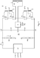
- the FIG. 1 shows the primary part of a switching power supply S with a three-level phase shift topology.
- the three phases L1, L2, L3 of a feeding network supplied via an isolating transformer (not shown here) are rectified in a first rectifier G1.
- a DC link ZK is charged from two capacitors C1, C2 connected in series between the positive and negative potential + UZ, -UZ of the DC voltage.
- the DC link capacitors C1, C2 with a capacity of 690 ⁇ F each smooth the DC voltage generated by the rectifier G1, and provide an average, between the upper and lower potential + UZ, -UZ of the DC voltage lying potential 0V available.
- the upper or lower potential of the intermediate circuit ZK is therefore + 280V or -280V with respect to the mean potential of 0V.
- a first terminal of a primary winding NP of the transformer T of the switching power supply S is alternately connected to the positive or negative potential + UZ, -UZ of the intermediate circuit ZK, so that at this terminal a square-wave voltage is applied, which jumps between -280V and 280V.
- the second terminal of the primary winding NP is connected to the middle potential 0V between the two DC link capacitors C1, C2.
- the current flowing in the primary winding NP current is detected by means of a current measuring unit C and provided its value via a current sense transformer ST subsequent electronics available (via terminal 5, see also FIG. 2 ).
- the semiconductor switches T1, T2, T3, T4 are driven by gate driver transformers GTT1, GTT2.
- GTT1, GTT2 gate driver transformers
- each resistor chain RK1, RK2 has a total resistance of 450k, so that the allowable voltage of 3.5mA is not exceeded. This is due to the distribution of this total resistance to several individual resistors in one of the resistor chains RK1, RK2 even if one of the individual resistors is defective and, for example, low impedance.
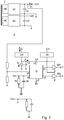
- the secondary part of the switching power supply is in the FIG. 2 presented together with the FIG. 1 is to be considered.
- the two sub-circuits are electrically connected to each other.
- a secondary winding NS which is the primary winding NP opposite, so that from the secondary winding NS after rectification by means of a second rectifier G2 necessary for the operation of an inverter DC voltage of 24V, for example.
- This DC voltage is smoothed and buffered with a first buffer capacitor C4.
- the primary winding NP opposite a self-supply winding NE is arranged, which is used to supply the switching power S in operation.
- a control device IC is used to drive two gate drivers GT1 and GT2, via which the two gate driver transformers GTT1 and GTT2, and thus ultimately the semiconductor switches T1, T2, T3, T4 are activated.
- the control device IC is formed as an integrated circuit, it generates the necessary for the pulse width modulated control of the semiconductor switches T1, T2, T3, T4 rectangular signals.
- the control device IC has the following connection pins: The supply voltage for the control device is present at pin p1, the reference potential at pin p2. Typically, such control devices IC turn on as soon as a voltage of 12V is applied between the input terminal EK and the reference potential terminal BK.
- the pins p3 and p4 serve to drive the gate drivers GT1, GT2.
- the pin p5 is used to measure the output voltage of the switching power supply S, which is tapped by means of a voltage divider from the output of the switching power supply S. Finally, the measured value of the current in the primary coil NP is present at the pin p6.
- control device IC calculates suitable control signals (PWM patterns) for the gate drivers GT1, GT2 on the basis of the information about the output voltage of the switched-mode power supply S and the current in the primary coil NP.
- these elements must be supplied by a start-up circuit with the necessary supply voltage.
- they each have an input terminal EK for the supply of the supply voltage and a reference potential terminal BK for a reference potential, which is also identified in the figures with a triangle.
- a supply capacitor C3 with a capacity of 230 ⁇ F is a central element of the starting circuit. This capacitor C3 is connected between the input terminal EK and the reference potential terminal BK. The voltage lying across the supply capacitor C3 thus corresponds to the supply voltage available to the control device IC and the gate drivers GT1, GT2.
- the starting circuit charges the supply capacitor C3 from the DC link ZK.
- the upper potential + UZ of the intermediate circuit ZK is connected via the first high-resistance resistor chain RK1 to the input terminal EK, wherein in the supply line still Current controller CR is located.
- the reference potential terminal BK is connected via the second resistor chain RK2 to the lower potential -UZ of the intermediate circuit ZK.
- the total current i flowing through the first resistor chain RK1 to the starting circuit is set to a fixed value by the current controller CR.
- This total current i is divided into a first partial flow i1 and a second partial flow i2.
- the valve V which is influenced by the current controller CR to keep the total current i constant
- the second partial current i2 on the one hand charges the supply capacitor C3, but also includes the leakage current to the control device IC.
- the AC voltage of the secondary winding NP is rectified by a second rectifier G2.
- the resulting DC voltage is smoothed by the first buffer capacitor C4 and fed via a diode D1 a voltage regulator VR.
- This voltage regulator VR outputs the voltage required for operation of the control device IC and the gate drivers GT1, GT2 to the input terminal EK.
- the AC voltage of the self-supply winding NE is rectified by a third rectifier G3.
- the resulting DC voltage is smoothed by a second buffer capacitor C5, and also fed to the voltage regulator SR to provide a sufficient supply voltage for operating the control device IC, even before the voltage at the first buffer capacitor C4 is sufficient.
- the capacitance value of the buffer capacitor C5 is 2 ⁇ F
- the capacitance value of the buffer capacitor C4 is higher with 10mF by more than three orders of magnitude. For this reason, the voltage increases on Buffer capacitor C5 much faster than at the buffer capacitor C4.
- the supply of the control device IC and gate driver GT1, GT2 is thus very quickly ensured by the buffer capacitor C5 and the downstream voltage regulator SR after the first start of the switching power supply S, before the voltage at the buffer capacitor C4 is sufficient to supply the control device IC and gate driver GT1 To ensure GT2.
- the diode D1 separates the two buffer capacitors C4 and C5 from each other.
- the power required for the operation of the switching power supply S for the control device IC and the gate drivers GT1, GT2 is about 2 watts. If the output current of the switched-mode power supply S is suddenly reduced, this leads to the control device IC reducing the pulse width in the primary winding NP of the transformer T in order to keep the output voltage at C4 and thus also the voltage at pin 5 of the control device IC constant.
- the pin 5 of the control device IC is an inverting input of an operational amplifier, which is connected as a PID controller. This serves to regulate the output voltage of the switched-mode power supply S. Due to the greatly differing capacitance values of C4 and C5, the reduced pulse width means that the voltage at C5 is no longer sufficient to maintain the supply voltage. In this case, the supply of the control device IC and the gate driver GT1, GT2 via the buffer capacitor C4, the diode D1 and the voltage regulator SR is ensured.
- the control device IC is thus fed after starting using the start-up circuit first from the supply capacitor C3 and from the self-supply winding NE and thus from the second buffer capacitor C5. As soon as the secondary winding NS has completely charged the significantly larger second buffer capacitor C4, its output voltage is also made available to the voltage regulator VR via D1.
- a fast intrinsic supply of the switching power supply S is ensured, and on the other hand, a stable buffering for operating states in which the transformer T can not supply enough energy, for example because the DC link voltage decreases briefly. This can be caused by a particularly high energy requirement of the motors connected to the inverter, for example when several axes have to be accelerated at the same time.
- the control device IC switches off the control signals of the four semiconductor switches T1, T2, T3, T4.
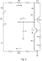
- a total current i of approx. 440 ⁇ A flows via the resistor chains RK1, RK2 into the starting circuit. This total current i also flows through the resistors R9 and R10.
- the current-dependent voltage drop across these resistors R9, R10 is measured by the bipolar transistor PNP and kept constant by varying the voltage at the collector of the bipolar transistor PNP. If the current through R9 and R10 becomes smaller, the voltage on the Collector from the bipolar transistor PNP. The acting as a valve V bipolar transistor is then more conductive, and the current through the resistors R9, R10 and R12 increases again.
- the circuit in FIG. 3 is dimensioned so that at a DC link voltage of 400V when switching on the control device, a first partial flow i1 flows through the resistor R12, whose value is between 190 ⁇ A and 290 ⁇ A.
- the leakage current or second partial current i2 of the control device IC is due to production scattering between 250 ⁇ A and 150 ⁇ A.
- the total current (total current i) of the two partial currents i1, i2, however, is constant 440 ⁇ A thanks to the current regulator CR.
- a defined switch-on point of the switched-mode power supply S is obtained, independently of Leakage current of the drive circuit IC installed in the respective device.
- the special, doubly configured supply of the switched-mode power supply S quickly establishes a secure supply after startup and is stable in all operating states.
Landscapes
- Engineering & Computer Science (AREA)
- Power Engineering (AREA)
- Dc-Dc Converters (AREA)
Applications Claiming Priority (1)
| Application Number | Priority Date | Filing Date | Title |
|---|---|---|---|
| DE102015207454.4A DE102015207454A1 (de) | 2015-04-23 | 2015-04-23 | Schaltnetzteil zur Versorgung eines Umrichters |
Publications (2)
| Publication Number | Publication Date |
|---|---|
| EP3089340A1 true EP3089340A1 (fr) | 2016-11-02 |
| EP3089340B1 EP3089340B1 (fr) | 2018-03-14 |
Family
ID=55229600
Family Applications (1)
| Application Number | Title | Priority Date | Filing Date |
|---|---|---|---|
| EP16152516.7A Active EP3089340B1 (fr) | 2015-04-23 | 2016-01-25 | Élement d'un reseau de distribution destine a alimenter un convertisseur |
Country Status (3)
| Country | Link |
|---|---|
| US (1) | US9923452B2 (fr) |
| EP (1) | EP3089340B1 (fr) |
| DE (1) | DE102015207454A1 (fr) |
Cited By (1)
| Publication number | Priority date | Publication date | Assignee | Title |
|---|---|---|---|---|
| DE102022132279A1 (de) | 2022-12-06 | 2024-06-06 | Ebm-Papst Mulfingen Gmbh & Co. Kg | Gleichspannungswandler und Verfahren zum Betreiben eines Gleichspannungswandlers |
Citations (7)
| Publication number | Priority date | Publication date | Assignee | Title |
|---|---|---|---|---|
| JPH01110060A (ja) * | 1987-10-22 | 1989-04-26 | Toshiba Corp | 電源装置 |
| EP0494327B1 (fr) | 1991-01-09 | 1996-04-10 | Siemens Aktiengesellschaft | Alimentateur à découpage à récupération |
| DE102008032316A1 (de) | 2008-07-09 | 2009-08-20 | Siemens Aktiengesellschaft | Stromversorgung für die Steuerelektronik eines Umrichters |
| EP2264884A2 (fr) * | 2009-06-11 | 2010-12-22 | Kabushiki Kaisha Toyota Jidoshokki | Dispositif d'onduleur |
| US20110234184A1 (en) * | 2010-03-26 | 2011-09-29 | Panasonic Corporation | Start-up in-rush current protection circuit for dcdc converter |
| US8629631B1 (en) * | 2011-07-21 | 2014-01-14 | Cooper Technologies Company | Method and system for improving start-up time of a light emitting diode (LED) driver at reduced input voltage |
| CN104410303A (zh) * | 2014-11-27 | 2015-03-11 | 成都芯源系统有限公司 | 一种高压电流源及其提供方法 |
Family Cites Families (19)
| Publication number | Priority date | Publication date | Assignee | Title |
|---|---|---|---|---|
| US3453519A (en) * | 1967-04-11 | 1969-07-01 | Thomas C Hunter Jr | Power responsive current regulator |
| US4460969A (en) * | 1980-12-04 | 1984-07-17 | The United States Of America As Represented By The Secretary Of The Army | Image spectrum analyzer for cartographic feature extraction |
| DE4111277A1 (de) * | 1991-04-08 | 1992-10-15 | Thomson Brandt Gmbh | Anlaufschaltung fuer ein schaltnetzteil |
| DE10002325A1 (de) * | 2000-01-20 | 2001-08-09 | Infineon Technologies Ag | Verfahren zum Anlaufen eines Schaltnetzteiles und Schaltnetzteil mit einer Anlaufschaltung |
| US6456511B1 (en) * | 2000-02-17 | 2002-09-24 | Tyco Electronics Corporation | Start-up circuit for flyback converter having secondary pulse width modulation |
| CN1248406C (zh) * | 2000-07-17 | 2006-03-29 | 东洋通信机株式会社 | 压电振荡器 |
| DE10347193A1 (de) * | 2003-10-10 | 2005-05-12 | Thomson Brandt Gmbh | Schaltnetzteil |
| US7136292B1 (en) * | 2005-07-29 | 2006-11-14 | Infineon Technologies Austria Ag | Power supply and method for regulating supply voltage |
| DE102005039867B4 (de) * | 2005-08-23 | 2016-04-07 | Power Systems Technologies Gmbh | Eingangsschaltung für ein Schaltnetzteil |
| US8363436B2 (en) * | 2009-12-10 | 2013-01-29 | Microsemi Corporation | Non-dissipative start up circuit |
| US9041311B2 (en) * | 2010-03-26 | 2015-05-26 | Cree Led Lighting Solutions, Inc. | Dynamic loading of power supplies |
| TWI440288B (zh) * | 2011-03-11 | 2014-06-01 | Neoenergy Microelectronics Inc | 具有加速啓動功能之啓動控制電路及其操作方法 |
| EP2512021B1 (fr) * | 2011-04-14 | 2017-07-19 | Nxp B.V. | Contrôleur pour un convertisseur de puissance en mode commuté |
| US9048747B2 (en) * | 2011-11-23 | 2015-06-02 | Zahid Ansari | Switched-mode power supply startup circuit, method, and system incorporating same |
| CN104429159A (zh) * | 2011-12-16 | 2015-03-18 | 替代照明科技公司 | 近似单位功率因数、寿命长、成本低的led灯改进系统及方法 |
| DE102012205335A1 (de) * | 2012-04-02 | 2013-10-02 | Dr. Johannes Heidenhain Gmbh | Wechselrichter |
| US8933681B2 (en) * | 2012-04-30 | 2015-01-13 | Intersil Americas Inc. | Integrated power supply with wide input supply voltage range |
| US9337720B2 (en) * | 2014-01-06 | 2016-05-10 | Bel Fuse (Macao Commercial Offshore) Limited | Switching power supply startup circuit having normally on emitter-switched current source |
| US9241380B2 (en) * | 2014-03-04 | 2016-01-19 | Osram Sylvania Inc. | Hybrid dimming control techniques for lighting drivers |
-
2015
- 2015-04-23 DE DE102015207454.4A patent/DE102015207454A1/de not_active Withdrawn
-
2016
- 2016-01-25 EP EP16152516.7A patent/EP3089340B1/fr active Active
- 2016-04-05 US US15/090,630 patent/US9923452B2/en active Active
Patent Citations (7)
| Publication number | Priority date | Publication date | Assignee | Title |
|---|---|---|---|---|
| JPH01110060A (ja) * | 1987-10-22 | 1989-04-26 | Toshiba Corp | 電源装置 |
| EP0494327B1 (fr) | 1991-01-09 | 1996-04-10 | Siemens Aktiengesellschaft | Alimentateur à découpage à récupération |
| DE102008032316A1 (de) | 2008-07-09 | 2009-08-20 | Siemens Aktiengesellschaft | Stromversorgung für die Steuerelektronik eines Umrichters |
| EP2264884A2 (fr) * | 2009-06-11 | 2010-12-22 | Kabushiki Kaisha Toyota Jidoshokki | Dispositif d'onduleur |
| US20110234184A1 (en) * | 2010-03-26 | 2011-09-29 | Panasonic Corporation | Start-up in-rush current protection circuit for dcdc converter |
| US8629631B1 (en) * | 2011-07-21 | 2014-01-14 | Cooper Technologies Company | Method and system for improving start-up time of a light emitting diode (LED) driver at reduced input voltage |
| CN104410303A (zh) * | 2014-11-27 | 2015-03-11 | 成都芯源系统有限公司 | 一种高压电流源及其提供方法 |
Non-Patent Citations (1)
| Title |
|---|
| G. KÄCSOR; P. SPANIK; J. DUDRIK; M. LUFT; E. SZYCHTA: "Principles of Operation of Three-level Phase Shift controlled Converter", ELECTRONICS AND ELECTRICAL ENGINEERING, vol. 2, no. 82, 2008 |
Cited By (1)
| Publication number | Priority date | Publication date | Assignee | Title |
|---|---|---|---|---|
| DE102022132279A1 (de) | 2022-12-06 | 2024-06-06 | Ebm-Papst Mulfingen Gmbh & Co. Kg | Gleichspannungswandler und Verfahren zum Betreiben eines Gleichspannungswandlers |
Also Published As
| Publication number | Publication date |
|---|---|
| US9923452B2 (en) | 2018-03-20 |
| DE102015207454A1 (de) | 2016-10-27 |
| EP3089340B1 (fr) | 2018-03-14 |
| US20160315546A1 (en) | 2016-10-27 |
Similar Documents
| Publication | Publication Date | Title |
|---|---|---|
| DE102012214832B4 (de) | Notlichtgerät mit Potentialtrennung zwischen Leuchtmittel und Energiespeicher | |
| CH698835B1 (de) | Eigenstromversorgung für Stromrichterschaltertreiber. | |
| DE112017003632T5 (de) | Dc/dc-umrichter | |
| DE112004000209T5 (de) | Mehrphasiger Abwärtswandler mit programmierbarer Phasenauswahl | |
| DE102013213802A1 (de) | Überspannungsschutz für aktive Gleichrichter bei Lastabwurf | |
| DE112014004870T5 (de) | Energieumwandlungsvorrichtung | |
| DE102018221519A1 (de) | Fahrzeugseitige Ladevorrichtung | |
| DE102016104860A1 (de) | Leistungsumwandlungsschaltungssystem | |
| DE112009004565B4 (de) | Umwandlungssystem für elektrische leistung mit einem anpassbaren transformatorwindungsverhältnis für verbesserte effizienz | |
| DE102019005190A1 (de) | Eine vorrichtung und ein verfahren zum begrenzen des einschaltstroms eines einphaseneingangs in einem stromversorgungssystem | |
| EP3602762B1 (fr) | Onduleur | |
| EP3089340B1 (fr) | Élement d'un reseau de distribution destine a alimenter un convertisseur | |
| DE102015215608A1 (de) | Traktionsbatterie-Heizungsregelung | |
| EP2826126B1 (fr) | Dispositif électronique de puissance comportant une symétrisation d'un n ud de tension dans le circuit intermédiaire | |
| DE102017221635B4 (de) | Ermitteln einer Netzsystemart einer Energiequelle zum Aufladen eines elektrischen Energiespeichers | |
| WO2016142217A1 (fr) | Ensemble circuit comprenant un transformateur à prise médiane et mesure de la tension de sortie | |
| DE102022133309A1 (de) | Testanordnung und verfahren zur emulation der phasen-ströme eines elektromotors für ein prüfen eines leistungs-elektronischen steuergeräts | |
| WO2019015971A1 (fr) | Circuit convertisseur de tension et procédé servant à faire fonctionner un circuit convertisseur de tension | |
| EP1396925B1 (fr) | Circuit de charge pour un convertisseur | |
| EP3174204A1 (fr) | Procédé et dispositif de commande d'un élément de commande électrique ou électronique | |
| DE102018116972B3 (de) | Betriebsschaltkreis und Verfahren zum Betreiben einer elektrischen Last | |
| EP2528217A1 (fr) | Hacheur à deux quadrants | |
| EP0148260B1 (fr) | Unite regulee d'alimentation en courant electrique | |
| DE102009000395A1 (de) | Mehrfach-Schaltregler | |
| EP3673551B1 (fr) | Circuit d'alimentation en tension |
Legal Events
| Date | Code | Title | Description |
|---|---|---|---|
| PUAI | Public reference made under article 153(3) epc to a published international application that has entered the european phase |
Free format text: ORIGINAL CODE: 0009012 |
|
| AK | Designated contracting states |
Kind code of ref document: A1 Designated state(s): AL AT BE BG CH CY CZ DE DK EE ES FI FR GB GR HR HU IE IS IT LI LT LU LV MC MK MT NL NO PL PT RO RS SE SI SK SM TR |
|
| AX | Request for extension of the european patent |
Extension state: BA ME |
|
| 17P | Request for examination filed |
Effective date: 20170502 |
|
| RBV | Designated contracting states (corrected) |
Designated state(s): AL AT BE BG CH CY CZ DE DK EE ES FI FR GB GR HR HU IE IS IT LI LT LU LV MC MK MT NL NO PL PT RO RS SE SI SK SM TR |
|
| STAA | Information on the status of an ep patent application or granted ep patent |
Free format text: STATUS: REQUEST FOR EXAMINATION WAS MADE |
|
| GRAP | Despatch of communication of intention to grant a patent |
Free format text: ORIGINAL CODE: EPIDOSNIGR1 |
|
| STAA | Information on the status of an ep patent application or granted ep patent |
Free format text: STATUS: GRANT OF PATENT IS INTENDED |
|
| INTG | Intention to grant announced |
Effective date: 20171102 |
|
| GRAS | Grant fee paid |
Free format text: ORIGINAL CODE: EPIDOSNIGR3 |
|
| GRAA | (expected) grant |
Free format text: ORIGINAL CODE: 0009210 |
|
| STAA | Information on the status of an ep patent application or granted ep patent |
Free format text: STATUS: THE PATENT HAS BEEN GRANTED |
|
| AK | Designated contracting states |
Kind code of ref document: B1 Designated state(s): AL AT BE BG CH CY CZ DE DK EE ES FI FR GB GR HR HU IE IS IT LI LT LU LV MC MK MT NL NO PL PT RO RS SE SI SK SM TR |
|
| REG | Reference to a national code |
Ref country code: GB Ref legal event code: FG4D Free format text: NOT ENGLISH |
|
| REG | Reference to a national code |
Ref country code: CH Ref legal event code: EP Ref country code: AT Ref legal event code: REF Ref document number: 979768 Country of ref document: AT Kind code of ref document: T Effective date: 20180315 |
|
| REG | Reference to a national code |
Ref country code: IE Ref legal event code: FG4D Free format text: LANGUAGE OF EP DOCUMENT: GERMAN |
|
| REG | Reference to a national code |
Ref country code: DE Ref legal event code: R096 Ref document number: 502016000672 Country of ref document: DE |
|
| REG | Reference to a national code |
Ref country code: NL Ref legal event code: MP Effective date: 20180314 |
|
| REG | Reference to a national code |
Ref country code: LT Ref legal event code: MG4D |
|
| PG25 | Lapsed in a contracting state [announced via postgrant information from national office to epo] |
Ref country code: FI Free format text: LAPSE BECAUSE OF FAILURE TO SUBMIT A TRANSLATION OF THE DESCRIPTION OR TO PAY THE FEE WITHIN THE PRESCRIBED TIME-LIMIT Effective date: 20180314 Ref country code: CY Free format text: LAPSE BECAUSE OF FAILURE TO SUBMIT A TRANSLATION OF THE DESCRIPTION OR TO PAY THE FEE WITHIN THE PRESCRIBED TIME-LIMIT Effective date: 20180314 Ref country code: LT Free format text: LAPSE BECAUSE OF FAILURE TO SUBMIT A TRANSLATION OF THE DESCRIPTION OR TO PAY THE FEE WITHIN THE PRESCRIBED TIME-LIMIT Effective date: 20180314 Ref country code: HR Free format text: LAPSE BECAUSE OF FAILURE TO SUBMIT A TRANSLATION OF THE DESCRIPTION OR TO PAY THE FEE WITHIN THE PRESCRIBED TIME-LIMIT Effective date: 20180314 Ref country code: NO Free format text: LAPSE BECAUSE OF FAILURE TO SUBMIT A TRANSLATION OF THE DESCRIPTION OR TO PAY THE FEE WITHIN THE PRESCRIBED TIME-LIMIT Effective date: 20180614 |
|
| PG25 | Lapsed in a contracting state [announced via postgrant information from national office to epo] |
Ref country code: BG Free format text: LAPSE BECAUSE OF FAILURE TO SUBMIT A TRANSLATION OF THE DESCRIPTION OR TO PAY THE FEE WITHIN THE PRESCRIBED TIME-LIMIT Effective date: 20180614 Ref country code: RS Free format text: LAPSE BECAUSE OF FAILURE TO SUBMIT A TRANSLATION OF THE DESCRIPTION OR TO PAY THE FEE WITHIN THE PRESCRIBED TIME-LIMIT Effective date: 20180314 Ref country code: LV Free format text: LAPSE BECAUSE OF FAILURE TO SUBMIT A TRANSLATION OF THE DESCRIPTION OR TO PAY THE FEE WITHIN THE PRESCRIBED TIME-LIMIT Effective date: 20180314 Ref country code: SE Free format text: LAPSE BECAUSE OF FAILURE TO SUBMIT A TRANSLATION OF THE DESCRIPTION OR TO PAY THE FEE WITHIN THE PRESCRIBED TIME-LIMIT Effective date: 20180314 Ref country code: GR Free format text: LAPSE BECAUSE OF FAILURE TO SUBMIT A TRANSLATION OF THE DESCRIPTION OR TO PAY THE FEE WITHIN THE PRESCRIBED TIME-LIMIT Effective date: 20180615 |
|
| PG25 | Lapsed in a contracting state [announced via postgrant information from national office to epo] |
Ref country code: MT Free format text: LAPSE BECAUSE OF FAILURE TO SUBMIT A TRANSLATION OF THE DESCRIPTION OR TO PAY THE FEE WITHIN THE PRESCRIBED TIME-LIMIT Effective date: 20180314 |
|
| PG25 | Lapsed in a contracting state [announced via postgrant information from national office to epo] |
Ref country code: PL Free format text: LAPSE BECAUSE OF FAILURE TO SUBMIT A TRANSLATION OF THE DESCRIPTION OR TO PAY THE FEE WITHIN THE PRESCRIBED TIME-LIMIT Effective date: 20180314 Ref country code: EE Free format text: LAPSE BECAUSE OF FAILURE TO SUBMIT A TRANSLATION OF THE DESCRIPTION OR TO PAY THE FEE WITHIN THE PRESCRIBED TIME-LIMIT Effective date: 20180314 Ref country code: RO Free format text: LAPSE BECAUSE OF FAILURE TO SUBMIT A TRANSLATION OF THE DESCRIPTION OR TO PAY THE FEE WITHIN THE PRESCRIBED TIME-LIMIT Effective date: 20180314 Ref country code: NL Free format text: LAPSE BECAUSE OF FAILURE TO SUBMIT A TRANSLATION OF THE DESCRIPTION OR TO PAY THE FEE WITHIN THE PRESCRIBED TIME-LIMIT Effective date: 20180314 Ref country code: ES Free format text: LAPSE BECAUSE OF FAILURE TO SUBMIT A TRANSLATION OF THE DESCRIPTION OR TO PAY THE FEE WITHIN THE PRESCRIBED TIME-LIMIT Effective date: 20180314 Ref country code: AL Free format text: LAPSE BECAUSE OF FAILURE TO SUBMIT A TRANSLATION OF THE DESCRIPTION OR TO PAY THE FEE WITHIN THE PRESCRIBED TIME-LIMIT Effective date: 20180314 |
|
| PG25 | Lapsed in a contracting state [announced via postgrant information from national office to epo] |
Ref country code: SK Free format text: LAPSE BECAUSE OF FAILURE TO SUBMIT A TRANSLATION OF THE DESCRIPTION OR TO PAY THE FEE WITHIN THE PRESCRIBED TIME-LIMIT Effective date: 20180314 Ref country code: SM Free format text: LAPSE BECAUSE OF FAILURE TO SUBMIT A TRANSLATION OF THE DESCRIPTION OR TO PAY THE FEE WITHIN THE PRESCRIBED TIME-LIMIT Effective date: 20180314 Ref country code: CZ Free format text: LAPSE BECAUSE OF FAILURE TO SUBMIT A TRANSLATION OF THE DESCRIPTION OR TO PAY THE FEE WITHIN THE PRESCRIBED TIME-LIMIT Effective date: 20180314 |
|
| REG | Reference to a national code |
Ref country code: DE Ref legal event code: R097 Ref document number: 502016000672 Country of ref document: DE |
|
| PG25 | Lapsed in a contracting state [announced via postgrant information from national office to epo] |
Ref country code: PT Free format text: LAPSE BECAUSE OF FAILURE TO SUBMIT A TRANSLATION OF THE DESCRIPTION OR TO PAY THE FEE WITHIN THE PRESCRIBED TIME-LIMIT Effective date: 20180716 |
|
| PLBE | No opposition filed within time limit |
Free format text: ORIGINAL CODE: 0009261 |
|
| STAA | Information on the status of an ep patent application or granted ep patent |
Free format text: STATUS: NO OPPOSITION FILED WITHIN TIME LIMIT |
|
| PG25 | Lapsed in a contracting state [announced via postgrant information from national office to epo] |
Ref country code: DK Free format text: LAPSE BECAUSE OF FAILURE TO SUBMIT A TRANSLATION OF THE DESCRIPTION OR TO PAY THE FEE WITHIN THE PRESCRIBED TIME-LIMIT Effective date: 20180314 |
|
| 26N | No opposition filed |
Effective date: 20181217 |
|
| PG25 | Lapsed in a contracting state [announced via postgrant information from national office to epo] |
Ref country code: SI Free format text: LAPSE BECAUSE OF FAILURE TO SUBMIT A TRANSLATION OF THE DESCRIPTION OR TO PAY THE FEE WITHIN THE PRESCRIBED TIME-LIMIT Effective date: 20180314 |
|
| PG25 | Lapsed in a contracting state [announced via postgrant information from national office to epo] |
Ref country code: MC Free format text: LAPSE BECAUSE OF FAILURE TO SUBMIT A TRANSLATION OF THE DESCRIPTION OR TO PAY THE FEE WITHIN THE PRESCRIBED TIME-LIMIT Effective date: 20180314 |
|
| REG | Reference to a national code |
Ref country code: CH Ref legal event code: PL |
|
| PG25 | Lapsed in a contracting state [announced via postgrant information from national office to epo] |
Ref country code: LU Free format text: LAPSE BECAUSE OF NON-PAYMENT OF DUE FEES Effective date: 20190125 |
|
| REG | Reference to a national code |
Ref country code: BE Ref legal event code: MM Effective date: 20190131 |
|
| REG | Reference to a national code |
Ref country code: IE Ref legal event code: MM4A |
|
| PG25 | Lapsed in a contracting state [announced via postgrant information from national office to epo] |
Ref country code: BE Free format text: LAPSE BECAUSE OF NON-PAYMENT OF DUE FEES Effective date: 20190131 |
|
| PG25 | Lapsed in a contracting state [announced via postgrant information from national office to epo] |
Ref country code: LI Free format text: LAPSE BECAUSE OF NON-PAYMENT OF DUE FEES Effective date: 20190131 Ref country code: CH Free format text: LAPSE BECAUSE OF NON-PAYMENT OF DUE FEES Effective date: 20190131 |
|
| PG25 | Lapsed in a contracting state [announced via postgrant information from national office to epo] |
Ref country code: IE Free format text: LAPSE BECAUSE OF NON-PAYMENT OF DUE FEES Effective date: 20190125 |
|
| PG25 | Lapsed in a contracting state [announced via postgrant information from national office to epo] |
Ref country code: TR Free format text: LAPSE BECAUSE OF FAILURE TO SUBMIT A TRANSLATION OF THE DESCRIPTION OR TO PAY THE FEE WITHIN THE PRESCRIBED TIME-LIMIT Effective date: 20180314 |
|
| PG25 | Lapsed in a contracting state [announced via postgrant information from national office to epo] |
Ref country code: IS Free format text: LAPSE BECAUSE OF FAILURE TO SUBMIT A TRANSLATION OF THE DESCRIPTION OR TO PAY THE FEE WITHIN THE PRESCRIBED TIME-LIMIT Effective date: 20180714 |
|
| PG25 | Lapsed in a contracting state [announced via postgrant information from national office to epo] |
Ref country code: HU Free format text: LAPSE BECAUSE OF FAILURE TO SUBMIT A TRANSLATION OF THE DESCRIPTION OR TO PAY THE FEE WITHIN THE PRESCRIBED TIME-LIMIT; INVALID AB INITIO Effective date: 20160125 |
|
| REG | Reference to a national code |
Ref country code: AT Ref legal event code: MM01 Ref document number: 979768 Country of ref document: AT Kind code of ref document: T Effective date: 20210125 |
|
| PG25 | Lapsed in a contracting state [announced via postgrant information from national office to epo] |
Ref country code: AT Free format text: LAPSE BECAUSE OF NON-PAYMENT OF DUE FEES Effective date: 20210125 |
|
| PG25 | Lapsed in a contracting state [announced via postgrant information from national office to epo] |
Ref country code: MK Free format text: LAPSE BECAUSE OF FAILURE TO SUBMIT A TRANSLATION OF THE DESCRIPTION OR TO PAY THE FEE WITHIN THE PRESCRIBED TIME-LIMIT Effective date: 20180314 |
|
| PGFP | Annual fee paid to national office [announced via postgrant information from national office to epo] |
Ref country code: DE Payment date: 20250121 Year of fee payment: 10 |
|
| PGFP | Annual fee paid to national office [announced via postgrant information from national office to epo] |
Ref country code: FR Payment date: 20250127 Year of fee payment: 10 |
|
| PGFP | Annual fee paid to national office [announced via postgrant information from national office to epo] |
Ref country code: IT Payment date: 20250129 Year of fee payment: 10 Ref country code: GB Payment date: 20250128 Year of fee payment: 10 |