EP3088096B1 - Devices and method for the pressure forming of connector bridges between parts of a board-shaped workpiece - Google Patents
Devices and method for the pressure forming of connector bridges between parts of a board-shaped workpiece Download PDFInfo
- Publication number
- EP3088096B1 EP3088096B1 EP15165673.3A EP15165673A EP3088096B1 EP 3088096 B1 EP3088096 B1 EP 3088096B1 EP 15165673 A EP15165673 A EP 15165673A EP 3088096 B1 EP3088096 B1 EP 3088096B1
- Authority
- EP
- European Patent Office
- Prior art keywords
- forming
- workpiece
- tool
- connecting web
- parts
- Prior art date
- Legal status (The legal status is an assumption and is not a legal conclusion. Google has not performed a legal analysis and makes no representation as to the accuracy of the status listed.)
- Active
Links
- 238000000034 method Methods 0.000 title claims description 31
- 239000002184 metal Substances 0.000 claims description 87
- 238000003754 machining Methods 0.000 claims description 56
- 238000005520 cutting process Methods 0.000 claims description 25
- 239000000463 material Substances 0.000 claims description 14
- 238000000926 separation method Methods 0.000 claims description 10
- 238000011156 evaluation Methods 0.000 claims description 8
- 230000000694 effects Effects 0.000 claims description 3
- 238000007493 shaping process Methods 0.000 description 61
- 238000012545 processing Methods 0.000 description 32
- 210000000056 organ Anatomy 0.000 description 12
- 238000003698 laser cutting Methods 0.000 description 9
- 230000008569 process Effects 0.000 description 9
- 230000001419 dependent effect Effects 0.000 description 5
- 238000013461 design Methods 0.000 description 5
- 238000004080 punching Methods 0.000 description 4
- 238000013459 approach Methods 0.000 description 3
- 239000002245 particle Substances 0.000 description 3
- 238000011161 development Methods 0.000 description 2
- 239000007787 solid Substances 0.000 description 2
- 230000009471 action Effects 0.000 description 1
- 239000011324 bead Substances 0.000 description 1
- 238000010276 construction Methods 0.000 description 1
- 238000006073 displacement reaction Methods 0.000 description 1
- 238000007654 immersion Methods 0.000 description 1
- 238000012805 post-processing Methods 0.000 description 1
- 230000009467 reduction Effects 0.000 description 1
- 239000012858 resilient material Substances 0.000 description 1
- 238000010008 shearing Methods 0.000 description 1
- 230000007704 transition Effects 0.000 description 1
- 239000002699 waste material Substances 0.000 description 1
Images


Classifications
-
- B—PERFORMING OPERATIONS; TRANSPORTING
- B21—MECHANICAL METAL-WORKING WITHOUT ESSENTIALLY REMOVING MATERIAL; PUNCHING METAL
- B21D—WORKING OR PROCESSING OF SHEET METAL OR METAL TUBES, RODS OR PROFILES WITHOUT ESSENTIALLY REMOVING MATERIAL; PUNCHING METAL
- B21D37/00—Tools as parts of machines covered by this subclass
- B21D37/10—Die sets; Pillar guides
-
- B—PERFORMING OPERATIONS; TRANSPORTING
- B21—MECHANICAL METAL-WORKING WITHOUT ESSENTIALLY REMOVING MATERIAL; PUNCHING METAL
- B21D—WORKING OR PROCESSING OF SHEET METAL OR METAL TUBES, RODS OR PROFILES WITHOUT ESSENTIALLY REMOVING MATERIAL; PUNCHING METAL
- B21D28/00—Shaping by press-cutting; Perforating
- B21D28/02—Punching blanks or articles with or without obtaining scrap; Notching
- B21D28/10—Incompletely punching in such a manner that the parts are still coherent with the work
-
- B—PERFORMING OPERATIONS; TRANSPORTING
- B21—MECHANICAL METAL-WORKING WITHOUT ESSENTIALLY REMOVING MATERIAL; PUNCHING METAL
- B21D—WORKING OR PROCESSING OF SHEET METAL OR METAL TUBES, RODS OR PROFILES WITHOUT ESSENTIALLY REMOVING MATERIAL; PUNCHING METAL
- B21D28/00—Shaping by press-cutting; Perforating
- B21D28/02—Punching blanks or articles with or without obtaining scrap; Notching
- B21D28/16—Shoulder or burr prevention, e.g. fine-blanking
-
- B—PERFORMING OPERATIONS; TRANSPORTING
- B21—MECHANICAL METAL-WORKING WITHOUT ESSENTIALLY REMOVING MATERIAL; PUNCHING METAL
- B21D—WORKING OR PROCESSING OF SHEET METAL OR METAL TUBES, RODS OR PROFILES WITHOUT ESSENTIALLY REMOVING MATERIAL; PUNCHING METAL
- B21D28/00—Shaping by press-cutting; Perforating
- B21D28/24—Perforating, i.e. punching holes
- B21D28/34—Perforating tools; Die holders
Definitions
- the invention also relates to a method for pressure forming a connecting web of the type mentioned, carried out by means of the above forming tool and / or by means of the above machine tool.
- the previously known forming tool comprises a forming punch with a beveled punch tip and a forming die with a flat support surface and a die recess embedded in the flat support surface.
- the forming die is the one who Forming die assigned to the other side of a connecting web to be machined. The forming die is moved in the direction of the forming die with a machining stroke carried out along a stroke axis.
- the forming die acts on the connecting web, which is arranged between the forming die and the forming die, with the beveled die tip.
- the connecting web is squeezed while reducing the thickness of the connecting web between the forming die and the forming die and also bent over an edge that is formed on the forming die by the support surface and a lateral boundary surface of the die recess running parallel to the stroke axis.
- a fracture zone with a reduced cross-section compared to the rest of the connecting web is generated on the connecting web.
- DE 10 2012 011 767 A1 discloses an apparatus and method for dicing a workpiece.
- a workpiece to be cut is acted upon on both sides by a cutting edge of a notching tool that is V-shaped in cross section.
- the cutting edges of the notching tool are moved towards one another along a movement axis.
- the tips of the cutting edges lie opposite one another along the axis of movement and penetrate the workpiece on the respectively assigned side of the workpiece, creating a notch geometry with a V-shaped cross-section, so that a residual thickness of the workpiece remains between the tips of the cutting edges.
- the workpiece is sheared along the previously created notch geometries and thus divided.
- U.S. 4,362,078 A relates to a device and a method for the punching processing of plate-like workpieces.
- a punch tool includes two Punch punches which are arranged on both sides of a workpiece to be processed and each of which has a raised circumferential edge with a V-shaped cross section. The tips of the circumferential edges of the punch lie opposite one another along a stroke axis of the punch.
- the punches are moved so far towards each other along the stroke axis that their circumferential edges penetrate the workpiece in question and create a V-shaped workpiece groove on the assigned workpiece sides, but do not yet create a cutout on the workpiece.
- a cutout is produced in a subsequent work step by shearing the workpiece along the V-shaped workpiece grooves.
- the object of the present invention is to provide devices and methods that make it possible to completely separate workpiece parts that are incompletely separated from one another and connected to one another via connecting webs, which are present as machining products of a separating machining of plate-like workpieces, in such a way that no or at least a slight Post-processing of the workpiece parts is required.
- this object is achieved by the forming tool and the machine tool according to claims 1 and 12 and by the methods according to claims 14, 15 and 17.
- a forming tool which, due to the geometry of the forming elements provided on the tool parts of the forming tool, during pressure forming of a connecting web that has remained between two workpiece parts at the end or ends of the connecting web creates a fracture zone which is such that after the breaking of the connecting web no traces, or at most only slight traces, of the connecting web remain on the workpiece part or parts.
- the forming elements of the tool parts dip into the latter and displace the material of the connecting web in the process. Due to the geometry of the shaping elements of the shaping tool, the material of the connecting web plasticized by the shaping tool is displaced away from the workpiece part or parts adjoining the connecting web.
- the material of the connecting web plasticized in the course of the forming process does not leave any traces or at most only slight traces on the workpiece part or parts concerned. Burrs formed on the connecting web are removed together with the connecting web and consequently do not impair the quality of the parting surface on the workpiece part or parts.
- the shaping elements on the tool parts of the shaping tool are offset from one another in the transverse direction of the stroke axis. This results in a gap between the forming members on both sides, which favors an oblique breaking off of the connecting web after forming.
- An inclined fracture surface on a workpiece part can, for example, be desirable in a case in which an inclined surface is also produced by machining the edges of the workpiece part, to which the inclined fracture surface on the workpiece part can then be matched.
- the tool parts of the forming tool according to the invention for forming a connecting web perform a single machining stroke or several successive machining strokes.
- the deformed end of the connecting web only has a relatively small cross section, which is dimensioned in such a way that the connection of the connecting web to the adjacent workpiece part with little effort, for example by moving the machined workpiece to and fro, is at least almost completely can be solved without burrs.
- the connecting web can be dimensioned before the pressure forming in such a way that it creates a load-bearing connection between the workpiece parts in question.
- good parts can be connected to one another, but also one or more good parts to a waste part, for example to a scrap skeleton, by connecting webs.
- the connecting webs can, for example, on straight or curved edges, but also on corners of each other place connected workpiece parts.
- the connecting webs should be aligned with respect to the forming members of the forming tool in such a way that the connecting webs face the forming members along the stroke axis with surfaces and not with edges. In the event of incomplete separation of the workpiece parts, torsion of the connecting webs about their longitudinal axis must therefore be avoided.
- material particles that arise, for example, as chips during the pressure forming of a connecting web can be removed from the processing point.
- at least one of the tool parts of the forming tool according to the invention is provided with a corresponding suction device. The removal of material particles from the processing point also prevents the material particles from leaving traces on the workpiece parts to be separated from one another and thereby reducing the quality of the workpiece processing.
- the tool parts of the forming tool according to the invention are arranged in tool holders, which are provided on opposite sides of the connecting web to be formed or the workpiece parts connected to one another by the connecting web to be formed and which can be moved relative to one another along the stroke axis of the tool parts under numerical control.
- tool holders which are provided on opposite sides of the connecting web to be formed or the workpiece parts connected to one another by the connecting web to be formed and which can be moved relative to one another along the stroke axis of the tool parts under numerical control.
- the workpiece previously machined to be parting usually rests on a conventional workpiece support of the machine tool.
- a connecting web to be formed is pressurized on both sides by the forming members of the tool parts of the forming tool according to the invention.
- the line along which the shaping elements dip at one end of the connecting web can run in the extension of a separating surface that was created on the adjacent workpiece part during the creation of the connecting web, but it can also be set back from this separating surface into the interior of the workpiece part . In the latter case, even if small remnants of the connecting bar remain on the workpiece part when the connecting bar is separated from the workpiece part, it is ensured that no remnants of the connecting bar protrude beyond the parting surface created on the workpiece part when the connecting bar was created.
- the shaping elements overlap with a workpiece part, preferably in the order of magnitude of tenths of a millimeter.
- the forming method according to the invention is part of the cutting method according to the invention and also part of the machining method according to the invention, in the course of which the separating method according to the invention and additionally a further workpiece machining are carried out.
- the forming tool according to the invention can be used to shape the connecting web (s) in a manner that is matched to the workpiece machining provided in addition to the separating machining.
- At least one of the tool parts has a support surface running essentially perpendicular to the stroke axis, from which the forming element of this tool part to the other Tool part protrudes.
- the support surface forms an abutment for the connecting web to be formed and thereby prevents undesired deformation of the processed connecting web.
- At least one of the shaping members has a triangular cross-section or a trapezoidal cross-section in a sectional plane running parallel to the stroke axis.
- a design of the forming tool according to the invention is preferred in which the forming element of one of the tool parts has a triangular cross-section and the forming element of the other tool part has a trapezoidal cross-section.
- the end face of a forming element with a triangular cross-section is in itself linear.
- such a shaping element can be provided with a slight flattening or rounding on the triangular tip forming the end face of the shaping element.
- a shaping element with a trapezoidal cross-section has a flat end face.
- Cross-sections which deviate from the trapezoidal shape and which form a flat end face on the respective shaping element are also conceivable according to the invention.
- Forming elements with a triangular or trapezoidal cross-section are provided in a development of the invention in that the forming element of a tool part is formed by a free end of the tool part provided with an inner cavity, preferably an inner cone (claim 5).
- an inner cavity preferably an inner cone (claim 5).
- material of the connecting web can flow off into the interior of the cavity formed, for example, by the inner cone. This reduces the resistance which the connecting web opposes to processing by the forming tool according to the invention.
- a radius or a bevel can be provided at the transition between the end face of the respective forming element and the inner cone. The radius and the bevel ensure, if necessary, that the reshaped connecting web does not break at this point during the final separation of the workpiece parts but rather directly at the attachment of the connecting web to the adjacent workpiece part.
- a separating surface is created on the workpiece side by the forming elements.
- At least one of the shaping elements on the workpiece side runs along the stroke axis parallel to the separating surface or at an angle to the separating surface on that workpiece part to which the workpiece side of the shaping element is facing during pressure shaping of the connecting web. If the workpiece side of a forming element is parallel to the separating surface on the workpiece part in question, the separating surface created by means of the forming element on the workpiece part in question also runs parallel to the separating surface of the workpiece part created before the pressure forming of the connecting web.
- a separating surface that runs parallel to the separating surface on the workpiece part in question is generated by means of the shaping element in particular when the separating surface generated by means of the shaping element extends as an extension of the separating surface already present on the workpiece part.
- the creation of a separating surface inclined at an angle with respect to the already existing separating surface of the workpiece part by means of the shaping element is, according to the invention, for example in cases provided, in which, before or after the forming of the connecting web, the existing separating surface on the workpiece part is formed by additional edge processing of the workpiece part and is beveled in the process.
- the inclined surface generated on the workpiece by means of the forming element is aligned with the inclined surface that is created as part of the additional edge processing of the workpiece part.
- the forming tool according to the invention is designed in such a way that the forming element of one of the tool parts on the workpiece part in question creates a separating surface that runs parallel to the existing separating surface of the workpiece part, while the forming element of the other tool part creates a separating surface that is at an angle opposite the already existing separation surface of the workpiece part.
- connecting web If a connecting web establishes a connection between two workpiece parts provided as good parts, the connecting web must be separated from both workpiece parts with as little residue as possible.
- Claim 8 relates to a design of the forming tool according to the invention which is provided for this purpose and which makes it possible to form a connecting web at the same time at several points spaced apart from one another along the connecting web.
- Each of the reshaping points on the connecting web is processed by two organ sections, one organ section being part of the shaping organ on one workpiece part and the other organ section being part of the shaping organ on the other workpiece part of the shaping tool according to the invention.
- the shaping elements on the two tool parts of the shaping tool according to the invention run in a circumferential direction and in particular in an arc-shaped manner, preferably along a circular arc, around the stroke axis.
- the extension of the shaping elements in the circumferential direction can be dimensioned in such a way that the shaping elements come to lie at several points of the connecting web at the same time when a connecting web is shaped.
- An arc-shaped, in particular a circular course of the deforming elements offers the possibility of arranging the fracture zone at which the connecting web is to break after the deformation on the workpiece part adjoining the connecting web in an area that is opposite to that on this workpiece part before the connecting web is deformed created parting surface is set back into the interior of the workpiece part.
- a circular course of the shaping elements is also advantageous insofar as by simply rotating the tool parts around a positioning axis concentric with the shaping elements, different organ sections of the shaping elements can be assigned to one and the same processing point and / or one and the same organ sections to different machining points.
- the successive use of different organ sections of a forming organ is particularly recommended because of the associated equalization of tool wear.
- At least one of the forming members is designed to be endless in the circumferential direction.
- shaping elements segmented in the circumferential direction are also conceivable.
- Claim 11 relates to a design of the forming tool according to the invention, which enables a force-dependent control of the machining stroke of the tool parts of the forming tool.
- a mutual support of the tool parts effective along the stroke axis while bypassing the pressure-formed connecting web is implemented in a preferred embodiment of the forming tool according to the invention by at least one of the Tool parts has a portal-like shape and engages over the connecting web to be formed while it is being processed.
- the portal supports of the relevant tool part can be placed on the other tool part laterally next to the connecting web at the end of the stroke position of the two tool parts.
- the shaping element can be arranged on the tool part or parts provided with at least one projection between the portal supports.
- the at least one connecting web when machining a plate-like workpiece from an elastically deformable material, is created as a solid body joint and is resilient in the transverse direction of the parting surfaces of the workpiece parts connected to one another by the connecting web. If such a connecting web is deformed by means of the forming tool according to the invention and pressurized at two points spaced apart from one another along the connecting web, in particular at both opposite ends of the connecting web, the area of the connecting web located between the two contact points of the forming tool can be made use of the elasticity of the connecting web be compressed. As a result, only a relatively small amount of force has to be applied to reshape the connecting web.
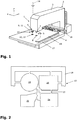
- a machine tool 1 is designed as a punch-laser combination machine.
- a machine frame 2 of the machine tool 1 has a C-shape and has an upper frame leg 3 and a lower frame leg 4. At the free ends of the upper frame leg 3 and the lower frame leg 4, a laser cutting station 5 and a forming station 6 are provided.
- the laser cutting station 5 comprises a laser cutting head 7 on the upper frame leg 3 and a laser beam holder 8 on the lower frame leg 4.
- the forming station 6 has an upper tool holder 9 on the upper frame leg 3 and a lower tool holder 10 on the lower frame leg 4.
- An upper tool embodied as a forming punch 11 is exchanged into the upper tool holder 9, and a lower tool embodied as a shaping die 12 is exchanged into the lower tool holder 10.
- the forming punch 11 and the forming die 12 are tool parts of a forming tool 13.
- the forming die 11 can be raised and lowered along a lifting axis 14 relative to the forming die 12.
- the upper tool holder 9 and the lower tool holder 10, together with the forming punch 11 and the forming die 12, can be adjusted to rotate about the lifting axis 14 (double arrow in Figure 1 ). All functions of the machine tool 1 are controlled by a programmable numerical control.
- Plate-like workpieces in the illustrated example a sheet metal 15, are processed at the laser cutting station 5 and at the forming station 6.
- the sheet metal 15 is moved by means of a conventional coordinate guide 16 with a two-axis horizontal movement over a workpiece support 17 of the machine tool 1 and relative to the laser cutting head 7 and the laser beam receptacle 8 and also relative to the forming tool 13.
- Figure 1 the plate 15 is shown broken off.
- the laser beam receptacle 8 and the lower tool receptacle 10 with the forming die 12 of the forming tool 13 can be seen in FIG.
- the sheet metal 15 is first machined in a separating manner at the laser cutting station 5.
- One possible result of the separating machining of the sheet metal 15 is shown in FIG Figure 2 shown. Accordingly, in the case of the laser cutting head 7 performed separating machining as workpiece parts in Figure 2 scrap skeleton 18, shown broken off, and sheet metal parts 19, 20, 21, 22 provided as good parts, incompletely separated from one another. Due to a movement of the sheet metal 15 generated by means of the coordinate guide 16, a laser beam directed from the laser cutting head 7 onto the sheet 15 cuts the sheet metal parts 19, 20, 21, 22 free, leaving the connecting webs 23 standing.
- the residual lattice 18 and the sheet metal parts 19, 20, 21, 22 are only incompletely separated from one another.
- a different type of cutting tool in particular a punching tool exchanged at the forming station 6, could also be used for incomplete separation of the residual lattice 18 and the sheet metal parts 19, 20, 21, 22.
- the sheet metal 15 is moved to the forming station 6 of the machine tool 1 by means of the coordinate guide 16.
- the connecting webs 23 are pressure-formed by means of the forming tool 13 that has been exchanged in the upper tool holder 9 and the lower tool holder 10.
- FIG Figure 3 the forming tool 13 with the forming die 11 provided as the upper tool and the forming die 12 provided as the lower tool is shown in FIG Figure 3 shown.
- the stroke axis 14 is indicated by dash-dotted lines on both the forming die 11 and the forming die 12, along which the forming die 11 is lowered relative to the forming die 12 with one machining stroke for pressure forming of a connecting web 23.
- a die-side shaping element 24 and a die-side shaping element 25 lie opposite one another along the stroke axis 14.
- a flat, circular end face 26 of the die-side forming element 24 and a circular end face 27 of the die-side forming element 25 point toward one another along the stroke axis 14.
- the free end of the forming die 11 is provided with an inner cone 28.
- the upper limit of the trapezoidal cross-section of the forming element 24 on the punch side is shown in FIG Figure 5 indicated by an imaginary dashed line.
- the die-side forming element 25 protrudes from a support surface 29 of the forming die 12 towards the forming die 11.
- the support surface 29 runs on the forming die 12 perpendicular to the stroke axis 14.
- the cross section of the die-side forming member 25 has the shape of an isosceles triangle, the base of which lies in the support surface 29 of the forming die 12 and the tip of which forms the linear end face 27 of the die-side forming member 25.
- Both the punch-side forming element 24 and the die-side shaping element 25 run endlessly along a circular line and thereby concentric with the stroke axis 14.
- the punch-side shaping element 24 and the die-side shaping element 25 are offset from one another, with the flat face 26 of the punch-side shaping element 24 lies within the linear end face 27 of the forming element 25 on the die side.
- the processed sheet metal 15 is positioned relative to the forming tool 13 exchanged at the forming station 6 by means of the coordinate guide 16 of the machine tool 1 in such a way that the forming tool 13 assumes a ready-to-process position opposite the connecting web 23 to be formed.
- the forming die 11 of the forming tool 13 is spaced along the stroke axis 14 from the top of the connecting web 23 and the workpiece parts adjoining it.
- the end face 27 of the shaping member 25 on the die side is at a minimal distance along the stroke axis 14 from the underside of the connecting web 23 and the workpiece parts connected by it.
- the vertical projection of the linear end face 27 of the die-side forming element 25 onto the machined sheet 15 runs concentrically with and radially outside the vertical projection of the end face 26 of the punch-side forming element 24.
- the forming punch 11 is moved with a processing stroke along the stroke axis 14 in the direction of the forming die 12 up to a stroke end position.
- the machining stroke is controlled as a function of the path, in the example according to the Figure 13 the machining stroke is controlled depending on the force.
- the amount of the machining stroke performed by the forming die 11 relative to the forming die 12 can be set variably and depends in particular on the desired remaining thickness of the connecting web 23 after the forming.
- the one covered by the forming die 11 along the stroke axis 14 Distance is recorded by means of a conventional position measuring system and forms the basis for the control of the lifting drive of the machine tool 1.
- the remaining thickness of the connecting web 23 is also determined by the height of the die-side forming element 25 measured along the stroke axis 14.
- FIG Figure 5 The conditions at the end of the stroke position of the forming die 11 are shown in FIG Figure 5 illustrated.
- the end faces 26, 27 of the stamp-side forming element 24 and the die-side forming element 25 are spaced apart from one another which is smaller than the thickness of the undeformed connecting web 23.
- the connecting web 23, the scrap skeleton 18 and the sheet metal part 20 are affected the impact by the forming die 11 is pressed with its underside against the support surface 29 of the forming die 12.
- the forming die 11 is immersed in the course of the machining stroke with diametrically opposite organ sections of the die-side forming member 24 at both ends of the connecting web 23 in this and in the adjoining areas of the residual lattice 18 and the sheet metal part 20.
- a workpiece side 31 of the forming element 24 on the punch side faces the residual lattice 18, and a workpiece side 32 of the forming element 24 on the punch side faces the sheet metal part 20.
- Web sides 33, 34 of the stamp-side forming member 24 point to the connecting web 23 and are accordingly facing away from the residual lattice 18 and the sheet metal part 20.
- the conditions at the die-side forming element 25 are represented.
- the die-side forming element 25 has two diametrically opposed organ sections at the ends of the connecting web in these and in regions of the residual lattice 18 and near the web of the sheet metal part 20 pressed in.
- Workpiece sides 35, 36 of the die-side forming element 25 face the scrap lattice 18 and the sheet metal part 20
- web sides 37, 38 of the die-side forming element 25 face away from the scrap lattice 18 and from the sheet metal part 20.
- the die-side forming element 24 has forming surfaces 40, 41.
- Forming surfaces 42, 43 are provided on the web sides 37, 38 of the die-side forming element 25.
- the shaping surfaces 40, 41 of the shaping element 24 on the punch side run, starting from the end face 26 of the shaping element 24 on the punch side, along the stroke axis 14 away from the workpiece sides 31, 32 of the shaping element 24 on the punch side.
- the shaping surfaces 42, 43 of the die-side shaping element 25 move away from the workpiece sides 35, 36 of the die-side shaping element 25 along the stroke axis 24.
- plasticized material of the connecting member 23 on the web sides 33, 34, 37, 38 of the forming member 24 on the punch side and the forming member 24 and the die side is produced under the action of the connecting web 23 being acted upon by the forming tool 13
- the forming element 25 is displaced towards the connecting web 23 and thus away from the workpiece sides 31, 32, 35, 36 of the forming element 24 on the punch side and the shaping element 25 on the die side.
- the pressure forming by means of the forming tool 13 reduces the cross section of the connecting web 23 along the stroke axis 14. Due to the oversize of the diameter of the end faces 26, 27 of the punch-side forming element 24 and of the die-side forming element 25 compared to the connecting web 23, the cross-sectional areas are reduced Approaches of the connecting web 23 on the residual lattice 18 and on the sheet metal part 20 set back opposite the separating surfaces 39 into the interior of the residual lattice 18 and the sheet metal part 20.
- a corresponding offset of the approaches of the cross-section-reduced connecting web 23 on the scrap lattice 18 and on the sheet metal part 20 occurs when the separating surfaces 39 on the scrap skeleton 18 and the sheet metal part 20 are already in the separating processing of the sheet metal 15 prior to the pressure forming of the connecting webs 23 with a be provided with a corresponding return ( Figure 6 ).
- the connecting web 23 and not also an area of the residual lattice 18 and the sheet metal part 20 immediately adjoining the connecting web 23 is to be machined during the pressure forming that follows the separating machining of the sheet metal 15. Accordingly, in the case of the processing situation, according to Figure 6 to apply a lower force for the pressure forming of the connecting web 23 than with the conditions according to FIG Figure 4 .
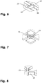
- FIG Figures 7 and 8 illustrate by way of example the processing of processing webs 23 intersecting in an X-shape, as they are of the type in FIG Figure 2 between the sheet metal parts 19, 20, 21, 22 are provided.
- Figure 7 relates to the case that not only the connecting webs 23 themselves but also directly adjacent workpiece areas are to be reshaped, while according to FIG Figure 8 Workpiece areas directly adjoining the connecting webs 23 have already been removed during the previous separating machining of the sheet metal 15 and consequently only the connecting webs 23 need to be reshaped.
- Figure 9 shows a connecting web 23 provided between two incompletely separated workpiece parts, which, like the rest of the separating machined workpiece, consists of a resilient material and which is also used in the incomplete separation of the adjacent workpiece parts a meander shape has been created. Due to the material and its special shape, the connecting web 23 is resilient and accordingly forms a solid body joint between the two adjacent workpiece parts. If the connecting web 23 according to Figure 9 in the in Figure 5 When pressurized by the forming die 11 and the forming die 12 of the forming tool 13 as illustrated, the connecting web 23 only offers a relatively small resistance to the pressure forming due to its resilience. The resilience of the connecting web 23 facilitates the displacement of plasticized material of the connecting web 23 away from the workpiece sides 31, 32, 35, 36 of the forming member 24 on the punch side and the forming member 25 on the die side.
- the Figures 10a, 10b and 10c show forming tools 13/1, 13/2, 13/3 structurally different from the forming tool 13, each in the circumference of a forming die 11/1, 11/2, 11/3.
- a forming element 24/1 on the punch side of the forming punch 11/1 unlike the forming element 24 of the forming punch 11 on the punch side, has an elliptical shape.
- the forming punch 11/2 is divided in a plane parallel to the stroke axis 14 and consequently has a two-part forming element 24/2 on the punch side, each segment of the forming element 24/2 on the punch side being semicircular.
- the forming die 11/3 has resulted from the forming die 11/1 by division along a plane running parallel to the stroke axis 14.
- a forming element 24/3 of the forming die 11/3 on the punch side is consequently also segmented and comprises two halves of identical construction.
- the reshaping punches 11/1, 11/2, 11/3 are assigned reshaping dies, not shown, with die-side reshaping elements, the geometry of which is adapted to the geometry of the reshaping elements 24/1, 24/2, 24/3 on the punch-side and which, moreover, are adapted to the die-side Forming element 25 of the forming die 12 of the forming tool 13 match.
- a pressure forming is carried out with several processing strokes of the forming tool 13/1 one after the other at the ends of connecting webs 23.
- the forming die 11/1 and the forming die assigned to it are set by rotating the upper tool holder 9 and the lower tool holder 10 of the machine tool 1 about the stroke axis 14.
- the processed sheet metal 15 is positioned relative to the forming tool 13/1 by means of the coordinate guide 16 of the machine tool 1.
- a simple connecting web 23 is processed by means of the forming tool 13/2.
- the forming tool 13/3 is used for pressure forming two connecting webs 23 intersecting in an X-shape.
- the forming tools 13/2, 13/3 perform pressure forming at both ends of a connecting web 23 with a single processing stroke, whereby two successive processing strokes of the forming tool 13/3 are required to process the two X-shaped crossing connecting webs 23 and the forming tool 13 / 3 is rotated about the stroke axis 14 after the first machining stroke.
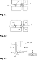
- a tool part of a forming tool 13/4 is designed as a forming punch 11/4.
- the forming punch 11/4 is a second tool part in Figure 13 Forming die 12, not shown, according to FIG Figure 3 assigned.
- a forming unit 44 of the forming die 11/4 corresponds to the forming die 11 according to FIG Figure 3 match.
- the forming die 11/4 ends in a die-side forming element 24/4 with a trapezoidal cross-section.
- the forming die 11/4 has cheeks 45, 46 which protrude from the forming element 24/4 of the forming die 11/4 on the die side along the stroke axis 14 to the forming die 12, not shown, and thereby projections 47, 48 of the forming die 11/4 train.
- the previously cut sheet metal 15 and the forming tool 13/4 are positioned relative to one another in such a way that during a processing stroke carried out by the forming die 11/4 to the forming die 12, the connecting web 23 to be formed is located between the projections 47, 48 of the Forming punch 11/4 comes to rest.
- the projections 47, 48 of the forming die 11/4 come into contact with the support surface 29 of the forming die 12 with their end faces leading along the stroke axis 14.
- the protrusion of the projections 47, 48 with respect to the die-side forming element 24/4 is dimensioned such that at the end of the stroke end position of the forming die 11/4 the end face of the punch-side forming element 24/4 is at a distance from the end face of the die-side forming element 25 along the stroke axis 14 , which corresponds to the desired remaining thickness of the pressure-formed connecting web 23.
- the forming die 11/4 overlaps the formed connecting web 23 like a portal.
- the projections 47, 48 of the forming die 11/4 are laterally adjacent to the connecting web 23 in the manner of portal supports.
- the machining stroke carried out by the forming punch 11/4 relative to the forming die 12 is force-controlled.
- an in Figure 13 Stroke control device 49 shown hinted at, for the stroke drive of the forming tool 13/4 integrated.
- the stroke control device 49 comprises a force measuring device 50, an evaluation device 51 and an actuating device 52.
- the force measuring device 50 measures the amount of support force with which the forming die 11/4 of the forming tool 13/4 is supported along the stroke axis 14 on the forming die 12.
- the evaluation device 51 the measured actual amount of the support force is compared with a limit amount of the support force stored in the stroke control device 49. If the measured actual amount of the supporting force reaches the predetermined limit amount, this indicates that the forming punch 11/4 along the stroke axis 14 has reached its stroke end position Has.
- the evaluation device 51 then generates a switching signal for the actuation device 52.
- the actuation device 52 actuates the stroke drive of the forming tool 13/4 to the effect that the processing stroke of the forming die 12 directed towards the forming die 12 ends and a Return stroke of the forming punch 11/4 is initiated in the opposite direction of the machining stroke.
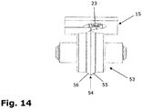
- Figure 14 illustrates a method step which is carried out in the machining of the sheet metal 15 in the illustrated example before the pressure forming of the connecting webs 23.
- sheet metal parts that are incompletely separated from one another are edge-machined on the underside by separating machining while leaving resilient connecting webs 23.
- a forming roller 53 is provided, which is exchanged in the lower tool holder 10 at the forming station 6 of the machine tool 1.
- the forming roller 53 acts when machining the sheet metal parts of a sheet metal previously machined in a separating manner with an in Figure 14 counterpressure roller, not shown, which is exchanged into the upper tool holder 9 of the machine tool 1 and which rests on the upper side of the processed sheet metal with a cylindrical outer surface.
- the forming roller 53 is provided with a double-conical bead 54 which has two conical forming surfaces 55, 56.
- the latter In order to carry out the edge processing of the incompletely separated sheet metal parts of the sheet metal that has been machined separately, the latter is moved by means of the coordinate guide 16 over the workpiece support 17 of the machine tool 1 in such a way that the forming roller 53 pressed against the sheet metal parts rolls along the edges of the sheet metal parts and thereby on the edges of the sheet metal parts generated by means of the forming surfaces 55, 56 inclined surfaces (chamfers).
- the approaches of the connecting webs 23 are cut out on the sheet metal parts.
- the connecting webs 23 are made by means of the Die-side forming member 25 of the forming tool 13 or by means of the die-side forming members of the forming tools 13/1, 13/2, 13/3, 13/4 created a corresponding inclined surface.
- the sheet metal parts in the example shown in FIG Figure 2 the sheet metal parts 19, 20, 21, 22 of the processed sheet 15, from the associated scrap skeleton (scrap skeleton 18 in Figure 2 ) solved. Due to the cross-sectional reduction of the connecting webs 23, shaking the processed sheet is sufficient for this. Due to the load acting here, the connecting webs 23 break in the fracture zones generated by pressure forming, whereby due to the geometry of the die-side forming elements 24, 24/1, 24/2, 24/3, 24/4 and the associated die-side forming elements of the forming tools 13, 13 / 1, 13/2, 13/3, 13/4 no or at most minimal traces of the connecting webs 23 remain on the sheet metal parts.
- the diameter-reduced attachments of the connecting webs 23 are set back into the interior of the sheet metal parts, remnants remaining on the sheet metal parts also protrude the connecting webs 23 do not protrude beyond the separating surfaces of the sheet metal parts created before the pressure forming of the connecting webs 23.
Landscapes
- Engineering & Computer Science (AREA)
- Mechanical Engineering (AREA)
- Mounting, Exchange, And Manufacturing Of Dies (AREA)
- Punching Or Piercing (AREA)
Description
Die Erfindung betrifft ein Umformwerkzeug sowie eine mit einem derartigen Umformwerkzeug versehene Werkzeugmaschine zum Druckumformen eines Verbindungsstegs, der an seinen Enden an Werkstückteilen ansetzt und der die Werkstückteile miteinander verbindet, die als Bearbeitungsprodukte einer trennenden Bearbeitung von plattenartigen Werkstücken, insbesondere von Blechen, vorliegen und die jeweils eine Trennfläche aufweisen, in deren Querrichtung der Verbindungssteg verläuft,
- mit zwei Werkzeugteilen, welche beim Druckumformen des Verbindungsstegs einander gegenüberliegenden Seiten des Verbindungsstegs zugeordnet sind und welche relativ zueinander längs einer Hubachse bewegbar sind, die beim Druckumformen des Verbindungsstegs in Querrichtung des Verbindungsstegs verläuft,
- wobei die Werkzeugteile an längs der Hubachse einander zugewandten Seiten jeweils mit einem Umformorgan versehen sind und freie Enden der Umformorgane mit Stirnseiten längs der Hubachse zueinander hinweisen,
- wobei jedes der Umformorgane eine Werkstückseite und eine Stegseite aufweist und beim Druckumformen des Verbindungsstegs die Werkstückseite der Umformorgane ein und demselben Werkstückteil zugewandt und die Stegseite der Umformorgane von diesem Werkstückteil abgewandt ist und
- wobei die Werkzeugteile längs der Hubachse mit einem Bearbeitungshub aufeinander zu in eine Hub-Endposition bewegbar sind, in welcher die Stirnseiten der Umformorgane längs der Hubachse einen Abstand voneinander aufweisen, der beim Druckumformen des Verbindungsstegs kleiner ist als die Erstreckung des umzuformenden Verbindungsstegs längs der Hubachse.
- with two tool parts which are assigned to opposite sides of the connecting web during pressure forming of the connecting web and which are movable relative to one another along a stroke axis which runs in the transverse direction of the connecting web during pressure forming of the connecting web,
- wherein the tool parts are each provided with a shaping element on sides facing one another along the stroke axis and free ends of the shaping elements with end faces point towards one another along the stroke axis,
- wherein each of the shaping elements has a workpiece side and a web side and, during pressure forming of the connecting web, the workpiece side of the shaping elements faces one and the same workpiece part and the web side of the shaping elements faces away from this workpiece part and
- wherein the tool parts can be moved along the stroke axis with a machining stroke towards one another into a stroke end position in which the end faces of the shaping elements are at a distance from one another along the stroke axis which, during pressure forming of the connecting web, is smaller than the extent of the connecting web to be reshaped along the stroke axis.
Die Erfindung betrifft außerdem ein mittels des vorstehenden Umformwerkzeugs und/oder mittels der vorstehenden Werkzeugmaschine durchgeführtes Verfahren zum Druckumformen eines Verbindungsstegs der genannten Art.The invention also relates to a method for pressure forming a connecting web of the type mentioned, carried out by means of the above forming tool and / or by means of the above machine tool.
Schließlich betrifft die Erfindung Verfahren zum Bearbeiten von plattenartigen Werkstücken, insbesondere zum Bearbeiten von Blechen, im Rahmen derer zwei Werkstückteile voneinander getrennt werden,
- indem die beiden Werkstückteile zunächst unter Erstellen einer Trennfläche an jedem der beiden Werkstückteile und unter Stehenlassen wenigstens eines Verbindungsstegs unvollständig voneinander getrennt werden, der an seinen Enden an den Werkstückteilen ansetzt, der die Werkstückteile miteinander verbindet und der in Querrichtung der Trennflächen verläuft,
- indem nach dem unvollständigen Trennen der Werkstückteile der Verbindungssteg druckumgeformt wird und
- indem die beiden Werkstückteile anschließend durch Lösen der durch den umgeformten Verbindungssteg hergestellten Verbindung vollständig voneinander getrennt werden.
- in that the two workpiece parts are initially incompletely separated from each other while creating a separating surface on each of the two workpiece parts and leaving at least one connecting web that attaches at its ends to the workpiece parts, which connects the workpiece parts to one another and which runs in the transverse direction of the separating surfaces,
- by pressure-forming the connecting web after the workpiece parts have been incompletely separated and
- in that the two workpiece parts are then completely separated from one another by loosening the connection established by the deformed connecting web.
Vorrichtungen und Verfahren mit den vorgenannten Merkmalen sind bekannt aus
Die Aufgabe der vorliegenden Erfindung besteht darin, Vorrichtungen und Verfahren bereitzustellen, die es ermöglichen, unvollständig voneinander getrennte und über Verbindungsstege miteinander verbundene Werkstückteile, die als Bearbeitungsprodukte einer trennenden Bearbeitung von plattenartigen Werkstücken vorliegen, derart vollständig voneinander zu trennen, dass keine oder allenfalls eine geringfügige Nachbearbeitung der Werkstückteile erforderlich ist.The object of the present invention is to provide devices and methods that make it possible to completely separate workpiece parts that are incompletely separated from one another and connected to one another via connecting webs, which are present as machining products of a separating machining of plate-like workpieces, in such a way that no or at least a slight Post-processing of the workpiece parts is required.
Erfindungsgemäß gelöst wird diese Aufgabe durch das Umformwerkzeug und die Werkzeugmaschine gemäß den Patentansprüchen 1 und 12 sowie durch die Verfahren gemäß den Patentansprüchen 14, 15 und 17.According to the invention, this object is achieved by the forming tool and the machine tool according to
Es wird von einem Umformwerkzeug Gebrauch gemacht, das aufgrund der Geometrie der an den Werkzeugteilen des Umformwerkzeugs vorgesehenen Umformorgane beim Druckumformen eines zwischen zwei Werkstückteilen stehengebliebenen Verbindungsstegs an dem oder den Enden des Verbindungsstegs eine Bruchzone erzeugt, die derart beschaffen ist, dass nach dem Brechen des Verbindungsstegs keine oder nur allenfalls geringfügige Spuren des Verbindungsstegs an dem oder den Werkstückteilen verbleiben. Die Umformorgane der Werkzeugteile tauchen beim Druckumformen eines Verbindungsstegs in diesen ein und verdrängen dabei Werkstoff des Verbindungsstegs. Aufgrund der Geometrie der Umformorgane des Umformwerkzeugs wird der durch das Umformwerkzeug plastifizierte Werkstoff des Verbindungsstegs von dem oder den an den Verbindungssteg angrenzenden Werkstückteilen weg verdrängt. Infolgedessen kann der im Laufe des Umformprozesses plastifizierte Werkstoff des Verbindungsstegs an dem oder den betreffenden Werkstückteilen keine oder allenfalls geringfügige Spuren hinterlassen. An dem Verbindungssteg gebildeter Grat wird gemeinsam mit dem Verbindungssteg entfernt und beeinträchtigt folglich die Qualität der Trennfläche an dem oder den Werkstückteilen nicht. Erfindungsgemäß sind die Umformorgane an den Werkzeugteilen des Umformwerkzeugs in Querrichtung der Hubachse gegeneinander versetzt. Dadurch ergibt sich zwischen den beiderseitigen Umformorganen ein Spalt, der ein schräges Abbrechen des Verbindungsstegs nach dem Umformen begünstigt. Eine schräge Bruchfläche an einem Werkstückteil kann beispielsweise in einem Fall erstrebenswert sein, in dem durch Kantenbearbeitung des Werkstückteils ebenfalls eine Schrägfläche erzeugt wird, auf welche die schräge Bruchfläche an dem Werkstückteil dann abgestimmt sein kann.Use is made of a forming tool which, due to the geometry of the forming elements provided on the tool parts of the forming tool, during pressure forming of a connecting web that has remained between two workpiece parts at the end or ends of the connecting web creates a fracture zone which is such that after the breaking of the connecting web no traces, or at most only slight traces, of the connecting web remain on the workpiece part or parts. During the pressure forming of a connecting web, the forming elements of the tool parts dip into the latter and displace the material of the connecting web in the process. Due to the geometry of the shaping elements of the shaping tool, the material of the connecting web plasticized by the shaping tool is displaced away from the workpiece part or parts adjoining the connecting web. As a result, the In the course of the forming process, the material of the connecting web plasticized in the course of the forming process does not leave any traces or at most only slight traces on the workpiece part or parts concerned. Burrs formed on the connecting web are removed together with the connecting web and consequently do not impair the quality of the parting surface on the workpiece part or parts. According to the invention, the shaping elements on the tool parts of the shaping tool are offset from one another in the transverse direction of the stroke axis. This results in a gap between the forming members on both sides, which favors an oblique breaking off of the connecting web after forming. An inclined fracture surface on a workpiece part can, for example, be desirable in a case in which an inclined surface is also produced by machining the edges of the workpiece part, to which the inclined fracture surface on the workpiece part can then be matched.
Je nach Anwendungsfall, beispielsweise je nach Bemessung der Breite des Verbindungsstegs einerseits und der Breite der Umformorgane andererseits, führen die Werkzeugteile des erfindungsgemäßen Umformwerkzeugs zum Umformen eines Verbindungsstegs einen einzelnen Bearbeitungshub oder mehrere aufeinanderfolgende Bearbeitungshübe aus.Depending on the application, for example depending on the dimensioning of the width of the connecting web on the one hand and the width of the forming elements on the other hand, the tool parts of the forming tool according to the invention for forming a connecting web perform a single machining stroke or several successive machining strokes.
Nach dem Druckumformen eines Verbindungsstegs besitzt das umgeformte Ende des Verbindungsstegs nur noch einen verhältnismäßig kleinen Querschnitt, der derart bemessen ist, dass die Anbindung des Verbindungsstegs an den benachbarten Werkstückteil mit geringem Kraftaufwand, beispielsweise durch Hin- und Herbewegen des bearbeiteten Werkstücks, zumindest annähernd restlos und gratfrei gelöst werden kann. Dessen ungeachtet kann der Verbindungssteg vor dem Druckumformen derart dimensioniert sein, dass er eine belastbare Verbindung zwischen den betreffenden Werkstückteilen herstellt.After the pressure forming of a connecting web, the deformed end of the connecting web only has a relatively small cross section, which is dimensioned in such a way that the connection of the connecting web to the adjacent workpiece part with little effort, for example by moving the machined workpiece to and fro, is at least almost completely can be solved without burrs. Regardless of this, the connecting web can be dimensioned before the pressure forming in such a way that it creates a load-bearing connection between the workpiece parts in question.
Als Werkstückteile können Gutteile untereinander aber auch ein oder mehrere Gutteile mit einem Abfallteil, beispielsweise mit einem Restgitter, durch Verbindungsstege verbunden sein. Die Verbindungsstege können beispielsweise an geradlinig oder bogenförmig verlaufenden Kanten aber auch an Ecken der miteinander verbundenen Werkstückteile ansetzen. Im Interesse einer möglichst langen Standzeit des Umformwerkzeugs sollten die Verbindungsstege gegenüber den Umformorganen des Umformwerkzeugs derart ausgerichtet sein, dass die Verbindungsstege den Umformorganen längs der Hubachse mit Flächen und nicht mit Kanten gegenüberliegen. Beim unvollständigen Trennen der Werkstückteile ist deshalb eine Torsion der Verbindungsstege um ihre Längsachse zu vermeiden.As workpiece parts, good parts can be connected to one another, but also one or more good parts to a waste part, for example to a scrap skeleton, by connecting webs. The connecting webs can, for example, on straight or curved edges, but also on corners of each other place connected workpiece parts. In the interest of the longest possible service life of the forming tool, the connecting webs should be aligned with respect to the forming members of the forming tool in such a way that the connecting webs face the forming members along the stroke axis with surfaces and not with edges. In the event of incomplete separation of the workpiece parts, torsion of the connecting webs about their longitudinal axis must therefore be avoided.
Ebenfalls im Interesse einer Optimierung der Standzeit des erfindungsgemäßen Umformwerkzeugs können Werkstoffteilchen, die beim Druckumformen eines Verbindungsstegs beispielsweise als Späne anfallen, von der Bearbeitungsstelle abgeführt werden. Zu diesem Zweck ist in bevorzugter Ausgestaltung der Erfindung wenigstens einer der Werkzeugteile des erfindungsgemäßen Umformwerkzeugs mit einer entsprechenden Absaugung versehen. Durch das Abführen von Werkstoffteilchen von der Bearbeitungsstelle wird im Übrigen auch verhindert, dass die Werkstoffteilchen an den voneinander zu trennenden Werkstückteilen Spuren hinterlassen und dadurch die Qualität der Werkstückbearbeitung mindern.Also in the interest of optimizing the service life of the forming tool according to the invention, material particles that arise, for example, as chips during the pressure forming of a connecting web, can be removed from the processing point. For this purpose, in a preferred embodiment of the invention, at least one of the tool parts of the forming tool according to the invention is provided with a corresponding suction device. The removal of material particles from the processing point also prevents the material particles from leaving traces on the workpiece parts to be separated from one another and thereby reducing the quality of the workpiece processing.
An der erfindungsgemäßen Werkzeugmaschine sind die Werkzeugteile des erfindungsgemäßen Umformwerkzeugs in Werkzeugaufnahmen angeordnet, die an einander gegenüberliegenden Seiten des umzuformenden Verbindungsstegs bzw. der durch den umzuformenden Verbindungssteg miteinander verbundenen Werkstückteile vorgesehen sind und die numerisch gesteuert längs der Hubachse der Werkzeugteile relativ zueinander bewegt werden können. Außerdem kann die Möglichkeit bestehen, die Werkzeugaufnahmen gemeinsam mit den daran fixierten Werkzeugteilen um die Hubachse dreheinzustellen. Das zuvor trennend bearbeitete Werkstück ruht üblicherweise auf einer herkömmlichen Werkstückauflage der Werkzeugmaschine. Durch eine parallel zu der Plattenebene des bearbeiteten Werkstücks ausgeführte Relativbewegung der Werkstückteile und der Verbindungsstege einerseits und der Werkzeugaufnahmen der Werkzeugmaschine andererseits werden die Verbindungsstege gegenüber den in den Werkzeugaufnahmen gehaltenen Werkzeugteilen des Umformwerkzeugs zur Bearbeitung positioniert.On the machine tool according to the invention, the tool parts of the forming tool according to the invention are arranged in tool holders, which are provided on opposite sides of the connecting web to be formed or the workpiece parts connected to one another by the connecting web to be formed and which can be moved relative to one another along the stroke axis of the tool parts under numerical control. In addition, there can be the possibility of rotating the tool holders together with the tool parts fixed to them about the lifting axis. The workpiece previously machined to be parting usually rests on a conventional workpiece support of the machine tool. A relative movement of the workpiece parts and the connecting webs on the one hand and the tool holders of the machine tool on the other hand, parallel to the plate plane of the machined workpiece, positions the connecting webs with respect to the tool parts of the forming tool held in the tool holders for machining.
Während des Umformvorgangs wird ein umzuformender Verbindungssteg beidseits durch die Umformorgane der Werkzeugteile des erfindungsgemäßen Umformwerkzeugs druckbeaufschlagt. Die Linie, entlang derer die Umformorgane dabei an einem Ende des Verbindungsstegs eintauchen, kann in Verlängerung einer Trennfläche verlaufen, die an dem benachbarten Werkstückteil bei der Erzeugung des Verbindungsstegs erstellt worden ist, sie kann aber auch gegenüber dieser Trennfläche in das Innere des Werkstückteils zurückversetzt sein. In dem letztgenannten Fall ist selbst dann, wenn beim Trennen des Verbindungsstegs von dem Werkstückteil kleine Reste des Verbindungsstegs an dem Werkstückteil verbleiben, gewährleistet, dass keine Reste des Verbindungsstegs über die beim Erzeugen des Verbindungsstegs an dem Werkstückteil erstellte Trennfläche vorstehen. Gegebenenfalls überlappen die Umformorgane mit einem Werkstückteil vorzugsweise in der Größenordnung von Zehntelmillimetern.During the forming process, a connecting web to be formed is pressurized on both sides by the forming members of the tool parts of the forming tool according to the invention. The line along which the shaping elements dip at one end of the connecting web can run in the extension of a separating surface that was created on the adjacent workpiece part during the creation of the connecting web, but it can also be set back from this separating surface into the interior of the workpiece part . In the latter case, even if small remnants of the connecting bar remain on the workpiece part when the connecting bar is separated from the workpiece part, it is ensured that no remnants of the connecting bar protrude beyond the parting surface created on the workpiece part when the connecting bar was created. If necessary, the shaping elements overlap with a workpiece part, preferably in the order of magnitude of tenths of a millimeter.
Das erfindungsgemäße Umformverfahren ist Teil des erfindungsgemäßen Trennverfahrens und auch Teil des erfindungsgemäßen Bearbeitungsverfahrens, im Laufe dessen das erfindungsgemäße Trennverfahren und zusätzlich eine weitere Werkstückbearbeitung durchgeführt werden. Im Rahmen des erfindungsgemäßen Bearbeitungsverfahrens kann das erfindungsgemäße Umformwerkzeug dazu dienen, den oder die Verbindungsstege auf eine Art und Weise umzuformen, die auf die zusätzlich zu der trennenden Bearbeitung vorgesehene Werkstückbearbeitung abgestimmt ist. Insbesondere besteht die Möglichkeit, beim Umformen des oder der Verbindungsstege an einem Werkstückteil Geometrien zu erzeugen, wie sie im Rahmen der zusätzlichen Werkstückbearbeitung an der restlichen Trennfläche des betreffenden Werkstückteils hergestellt werden.The forming method according to the invention is part of the cutting method according to the invention and also part of the machining method according to the invention, in the course of which the separating method according to the invention and additionally a further workpiece machining are carried out. Within the scope of the machining method according to the invention, the forming tool according to the invention can be used to shape the connecting web (s) in a manner that is matched to the workpiece machining provided in addition to the separating machining. In particular, there is the possibility, when reshaping the connecting web or webs, to generate geometries on a workpiece part such as are produced in the context of the additional workpiece machining on the remaining separating surface of the workpiece part in question.
Besondere Ausführungsarten der Erfindung nach den unabhängigen Patentansprüchen ergeben sich aus den abhängigen Patentansprüchen 2 bis 11, 13 und 16.Special embodiments of the invention according to the independent patent claims emerge from the dependent patent claims 2 to 11, 13 and 16.
Gemäß Patentanspruch 2 ist in bevorzugter Ausgestaltung des erfindungsgemäßen Umformwerkzeugs vorgesehen, dass wenigstens einer der Werkzeugteile eine im Wesentlichen senkrecht zu der Hubachse verlaufende Auflagefläche aufweist, von welcher das Umformorgan dieses Werkzeugteils zu dem anderen Werkzeugteil hin vorsteht. Die Auflagefläche bildet während des Umformprozesses ein Widerlager für den umzuformenden Verbindungssteg und verhindert dadurch eine unerwünschte Deformation des bearbeiteten Verbindungsstegs.According to
Für die Umformorgane der Werkzeugteile des erfindungsgemäßen Umformwerkzeugs kommen unterschiedliche Geometrien in Frage.Different geometries can be used for the shaping elements of the tool parts of the shaping tool according to the invention.
Gemäß Patentanspruch 3 weist wenigstens eines der Umformorgane in einer parallel zu der Hubachse verlaufenden Schnittebene einen dreiecksförmigen Querschnitt oder einen trapezförmigen Querschnitt auf. Bevorzugt wird ausweislich Patentanspruch 4 eine Bauart des erfindungsgemäßen Umformwerkzeugs, im Falle derer das Umformorgan eines der Werkzeugteile einen dreiecksförmigen Querschnitt und das Umformorgan des anderen Werkzeugteils einen trapezförmigen Querschnitt aufweist. Die Stirnseite eines Umformorgans mit Dreiecksquerschnitt ist an sich linienförmig. Zur Erhöhung der Standzeit kann ein derartiges Umformorgan in bevorzugter Ausgestaltung der Erfindung mit einer geringfügigen Abflachung oder Abrundung an der die Stirnseite des Umformorgans ausbildenden Dreiecksspitze versehen sein. Abweichend von einem Umformorgan mit Dreiecksquerschnitt besitzt ein Umformorgan mit trapezförmigem Querschnitt eine flächige Stirnseite. Auch von der Trapezform abweichende Querschnitte, die an dem betreffenden Umformorgan eine flächige Stirnseite ausbilden, sind erfindungsgemäß denkbar.According to
Umformorgane mit einem dreiecksförmigen oder mit einem trapezförmigen Querschnitt werden in Weiterbildung der Erfindung dadurch bereitgestellt, dass das Umformorgan eines Werkzeugteils von einem mit einem Innenhohlraum, vorzugsweise einem Innenkonus versehenen freien Ende des Werkzeugteils gebildet ist (Patentanspruch 5). Beim Druckumformen eines Verbindungsstegs kann Werkstoff des Verbindungsstegs in das Innere des beispielsweise von dem Innenkonus gebildeten Hohlraums abfließen. Dadurch reduziert sich der Widerstand, welchen der Verbindungssteg der Bearbeitung durch das erfindungsgemäße Umformwerkzeug entgegensetzt. In Weiterbildung der Erfindung kann an dem Übergang zwischen der Stirnseite des betreffenden Umformorgans und dem Innenkonus ein Radius oder eine Abschrägung vorgesehen sein. Der Radius und die Abschrägung sorgen gegebenenfalls dafür, dass der umgeformte Verbindungssteg bei der endgültigen Trennung der Werkstückteile nicht an dieser Stelle sondern vielmehr unmittelbar an dem Ansatz des Verbindungsstegs an dem benachbarten Werkstückteil bricht.Forming elements with a triangular or trapezoidal cross-section are provided in a development of the invention in that the forming element of a tool part is formed by a free end of the tool part provided with an inner cavity, preferably an inner cone (claim 5). During the pressure forming of a connecting web, material of the connecting web can flow off into the interior of the cavity formed, for example, by the inner cone. This reduces the resistance which the connecting web opposes to processing by the forming tool according to the invention. In a further development of the invention, at the transition between the end face of the respective forming element and the inner cone a radius or a bevel can be provided. The radius and the bevel ensure, if necessary, that the reshaped connecting web does not break at this point during the final separation of the workpiece parts but rather directly at the attachment of the connecting web to the adjacent workpiece part.
Beim Druckumformen des Verbindungsstegs und dem damit verbundenen Eintauchen der Umformorgane des erfindungsgemäßen Umformwerkzeugs an wenigstens einem Ende des Verbindungsstegs wird durch die Umformorgane werkstückseitig eine Trennfläche erstellt. Durch entsprechende Gestaltung der Umformorgane kann auf die Beschaffenheit der durch die Umformorgane erzeugten Trennfläche Einfluss genommen werden. Weist ein Umformorgan eine scharfe Kante auf, so erzeugt das Umformorgan eine glatte und somit qualitativ hochwertige Trennfläche.During the pressure forming of the connecting web and the associated immersion of the forming elements of the forming tool according to the invention at at least one end of the connecting web, a separating surface is created on the workpiece side by the forming elements. By appropriately designing the shaping elements, it is possible to influence the nature of the separating surface produced by the shaping elements. If a shaping element has a sharp edge, the shaping element produces a smooth and thus high-quality separating surface.
Im Falle der Erfindungsbauart gemäß Patentanspruch 6 ist vorgesehen, dass wenigstens eines der Umformorgane an der Werkstückseite längs der Hubachse parallel zu der Trennfläche oder unter einem Winkel gegenüber der Trennfläche an demjenigen Werkstückteil verläuft, welchem die Werkstückseite des Umformorgans beim Druckumformen des Verbindungsstegs zugewandt ist. Ist die Werkstückseite eines Umformorgans parallel zu der Trennfläche an dem betreffenden Werkstückteil, so verläuft auch die mittels des Umformorgans an dem betreffenden Werkstückteil erstellte Trennfläche parallel zu der vor dem Druckumformen des Verbindungsstegs erstellten Trennfläche des Werkstückteils. Verläuft die Werkstückseite des Umformorgans unter einem Winkel gegenüber der bereits vor dem Umformen des Verbindungsstegs erstellten Trennfläche an dem betreffenden Werkstückteil, so gilt Entsprechendes für die mittels des Umformorgans an dem Werkstückteil erzeugte Trennfläche. Eine parallel zu der Trennfläche an dem betreffenden Werkstückteil verlaufende Trennfläche wird mittels des Umformorgans erfindungsgemäß insbesondere dann erzeugt, wenn die mittels des Umformorgans erzeugte Trennfläche in Verlängerung der bereits vorhandenen Trennfläche an dem Werkstückteil verläuft. Die Erstellung einer unter einem Winkel gegen die bereits vorhandene Trennfläche des Werkstückteils geneigten Trennfläche mittels des Umformorgans ist erfindungsgemäß beispielsweise in Fällen vorgesehen, in denen vor oder nach dem Umformen des Verbindungsstegs die bereits vorhandene Trennfläche an dem Werkstückteil durch zusätzliche Kantenbearbeitung des Werkstückteils umgeformt und dabei abgeschrägt wird. Bei entsprechender Wahl des Winkels zwischen der Werkstückseite des Umformorgans und der bereits vorhandenen Trennfläche des Werkstückteils fluchtet die mittels des Umformorgans an dem Werkstück erzeugte Schrägfläche mit der Schrägfläche, die im Rahmen der zusätzlichen Kantenbearbeitung des Werkstückteils erstellt wird.In the case of the inventive design according to
Gemäß Patentanspruch 7 ist das erfindungsgemäße Umformwerkzeug derart gestaltet, dass das Umformorgan eines der Werkzeugteile an dem betreffenden Werkstückteil eine Trennfläche erzeugt, die parallel zu der bereits vorhandenen Trennfläche des Werkstückteils verläuft, während das Umformorgan des anderen Werkzeugteils eine Trennfläche erstellt, die unter einem Winkel gegenüber der bereits vorhandenen Trennfläche des Werkstückteils verläuft.According to
Stellt ein Verbindungssteg eine Verbindung zwischen zwei als Gutteile vorgesehenen Werkstückteilen her, so ist der Verbindungssteg von beiden Werkstückteilen möglichst rückstandslos zu trennen.If a connecting web establishes a connection between two workpiece parts provided as good parts, the connecting web must be separated from both workpiece parts with as little residue as possible.
Patentanspruch 8 betrifft eine zu diesem Zweck vorgesehene Bauart des erfindungsgemäßen Umformwerkzeugs, die es erlaubt, einen Verbindungssteg zeitgleich an mehreren längs des Verbindungsstegs voneinander beabstandeten Stellen umzuformen. Jede der Umformstellen an dem Verbindungssteg wird dabei durch zwei Organabschnitte bearbeitet, wobei der eine Organabschnitt Teil des Umformorgans an dem einen Werkstückteil und der andere Organabschnitt Teil des Umformorgans an dem anderen Werkstückteil des erfindungsgemäßen Umformwerkzeugs ist.
Zur Ausbildung von Organabschnitten, die verschiedenen Bearbeitungsstellen an einem Verbindungssteg zugeordnet sind, werden im Falle der Erfindung unterschiedliche Möglichkeiten zur konstruktiven Gestaltung der Umformorgane an den Werkzeugteilen des erfindungsgemäßen Umformwerkzeugs genutzt.To form organ sections that are assigned to different processing points on a connecting web, in the case of the invention, different possibilities for the structural design of the shaping elements on the tool parts of the shaping tool according to the invention are used.
Gemäß Patentanspruch 9 verlaufen die Umformorgane an den beiden Werkzeugteilen des erfindungsgemäßen Umformwerkzeugs in einer Umfangsrichtung und dabei insbesondere bogenförmig, vorzugsweise längs eines Kreisbogens, um die Hubachse. Die Erstreckung der Umformorgane in Umfangsrichtung kann dabei derart bemessen sein, dass die Umformorgane beim Umformen eines Verbindungsstegs gleichzeitig an mehreren Stellen des Verbindungsstegs zu liegen kommen. Ein bogenförmiger, insbesondere ein kreisförmiger Verlauf der Umformorgane bietet die Möglichkeit, die Bruchzone, an welcher der Verbindungssteg nach dem Umformen brechen soll, an dem an den Verbindungssteg anschließenden Werkstückteil in einem Bereich anzuordnen, der gegenüber der an diesem Werkstückteil bereits vor dem Umformen des Verbindungsstegs erstellten Trennfläche in das Innere des Werkstückteils zurückversetzt ist. Ein kreisförmiger Verlauf der Umformorgane ist darüber hinaus insofern vorteilhaft, als durch eine einfache Dreheinstellung der Werkzeugteile um eine mit den Umformorganen konzentrische Positionierachse unterschiedliche Organabschnitte der Umformorgane ein und derselben Bearbeitungsstelle und/oder ein und dieselben Organabschnitte unterschiedlichen Bearbeitungsstellen zugeordnet werden können. Der sukzessive Einsatz unterschiedlicher Organabschnitte eines Umformorgans empfiehlt sich insbesondere aufgrund der damit verbundenen Vergleichmäßigung des Werkzeugverschleißes.According to patent claim 9, the shaping elements on the two tool parts of the shaping tool according to the invention run in a circumferential direction and in particular in an arc-shaped manner, preferably along a circular arc, around the stroke axis. The extension of the shaping elements in the circumferential direction can be dimensioned in such a way that the shaping elements come to lie at several points of the connecting web at the same time when a connecting web is shaped. An arc-shaped, in particular a circular course of the deforming elements offers the possibility of arranging the fracture zone at which the connecting web is to break after the deformation on the workpiece part adjoining the connecting web in an area that is opposite to that on this workpiece part before the connecting web is deformed created parting surface is set back into the interior of the workpiece part. A circular course of the shaping elements is also advantageous insofar as by simply rotating the tool parts around a positioning axis concentric with the shaping elements, different organ sections of the shaping elements can be assigned to one and the same processing point and / or one and the same organ sections to different machining points. The successive use of different organ sections of a forming organ is particularly recommended because of the associated equalization of tool wear.
Gemäß Patentanspruch 10 ist in weiterer bevorzugter Ausgestaltung des erfindungsgemäßen Umformwerkzeugs wenigstens eines der Umformorgane in Umfangsrichtung endlos ausgebildet. Alternativ sind im Falle der Erfindung aber auch in Umfangsrichtung segmentierte Umformorgane denkbar.According to claim 10, in a further preferred embodiment of the forming tool according to the invention, at least one of the forming members is designed to be endless in the circumferential direction. Alternatively, in the case of the invention, shaping elements segmented in the circumferential direction are also conceivable.
An der erfindungsgemäßen Werkzeugmaschine nach Patentanspruch 13 ist der zum Druckumformen eines Verbindungsstegs auszuführende Bearbeitungshub kraftabhängig gesteuert. Patentanspruch 11 betrifft eine Bauart des erfindungsgemäßen Umformwerkzeugs, das eine kraftabhängige Steuerung des Bearbeitungshubs der Werkzeugteile des Umformwerkzeugs ermöglicht. Eine längs der Hubachse wirksame gegenseitige Abstützung der Werkzeugteile unter Umgehung des druckumgeformten Verbindungsstegs ist in bevorzugter Ausgestaltung des erfindungsgemäßen Umformwerkzeugs realisiert, indem wenigstens einer der Werkzeugteile eine portalartige Gestalt aufweist und den umzuformenden Verbindungssteg während dessen Bearbeitung übergreift. Die Portalstützen des betreffenden Werkzeugteils können bei Hub-Endposition der beiden Werkzeugteile auf dem anderen Werkzeugteil seitlich neben dem Verbindungssteg aufsetzen. Das Umformorgan kann an dem oder den mit wenigstens einem Vorsprung versehenen Werkzeugteilen zwischen den Portalstützen angeordnet sein.On the machine tool according to the invention according to
In bevorzugter Ausgestaltung des erfindungsgemäßen Trennverfahrens ist ausweislich Patentanspruch 16 vorgesehen, dass bei der Bearbeitung eines plattenartigen Werkstücks aus einem elastisch verformbaren Werkstoff der wenigstens eine Verbindungssteg als Festkörpergelenk erstellt wird und in Querrichtung der Trennflächen der durch den Verbindungssteg miteinander verbundenen Werkstückteile federelastisch ist. Wird ein derartiger Verbindungssteg mittels des erfindungsgemäßen Umformwerkzeugs umgeformt und dabei an zwei längs des Verbindungsstegs voneinander beabstandeten Stellen, insbesondere an beiden einander gegenüberliegenden Enden des Verbindungsstegs, druckbeaufschlagt, so kann der zwischen den beiden Angriffsstellen des Umformwerkzeugs gelegene Bereich des Verbindungsstegs unter Ausnutzung der Elastizität des Verbindungsstegs gestaucht werden. Zur Umformung des Verbindungsstegs ist folglich nur eine verhältnismäßig geringe Kraft aufzuwenden.In a preferred embodiment of the separation method according to the invention, it is evidenced by
Nachfolgend wird die Erfindung anhand beispielhafter schematischer Darstellungen näher erläutert.The invention is explained in more detail below with the aid of exemplary schematic representations.
Es zeigen:
- Figur 1
- eine Werkzeugmaschine für die Blechbearbeitung mit einer Schneidstation und einer Umformstation,
Figur 2- über Verbindungsstege miteinander verbundene Blechteile, erzeugt durch die Bearbeitung einer Blechtafel an der Werkzeugmaschine gemäß
Figur 1 , Figur 3- ein Umformwerkzeug erster Bauart zum Einsatz an der Umformstation der Werkzeugmaschine gemäß
Figur 1 , Figuren 4 bis 9- Darstellungen zur Veranschaulichung der Funktionsweise des Umformwerkzeugs gemäß
Figur 3 beim Umformen von zwischen zwei Blechteilen vorgesehenen Verbindungsstegen, - Figuren 10a, 10b, 10c
- die Oberwerkzeuge weiterer Bauarten eines Umformwerkzeugs zum Einsatz an der Umformstation der Werkzeugmaschine gemäß
Figur 1 , Figur 11- eine Darstellung zur Veranschaulichung der Funktionsweise des Umformwerkzeugs gemäß
Figur 10a , Figur 12- eine Darstellung zur Veranschaulichung der Funktionsweise des Umformwerkzeugs gemäß
Figur 10b und des Umformwerkzeugs gemäßFigur 10c , Figur 13- eine Variante des Umformwerkzeugs gemäß
Figur 3 zur Verwendung bei kraftabhängiger Steuerung eines von dem Umformwerkzeug ausgeführten Bearbeitungshubs und Figur 14- zwei über einen Verbindungssteg miteinander verbundene Blechteile während einer Kantenbearbeitung der Blechteile.
- Figure 1
- a machine tool for sheet metal processing with a cutting station and a forming station,
- Figure 2
- Sheet metal parts connected to one another via connecting webs, produced by machining a sheet metal on the machine tool according to
Figure 1 , - Figure 3
- a forming tool of the first type for use at the forming station of the machine tool according to FIG
Figure 1 , - Figures 4 to 9
- Representations to illustrate the functioning of the forming tool according to
Figure 3 when forming connecting webs between two sheet metal parts, - Figures 10a, 10b, 10c
- the upper tools of other types of a forming tool for use at the forming station of the machine tool according to FIG
Figure 1 , - Figure 11
- a representation to illustrate the functioning of the forming tool according to FIG
Figure 10a , - Figure 12
- a representation to illustrate the functioning of the forming tool according to FIG
Figure 10b and the forming tool according toFigure 10c , - Figure 13
- a variant of the forming tool according to
Figure 3 for use with force-dependent control of a machining stroke carried out by the forming tool and - Figure 14
- two sheet metal parts connected to one another via a connecting web during edge processing of the sheet metal parts.
Gemäß
Die Laser-Schneidstation 5 umfasst einen Laserschneidkopf 7 an dem oberen Gestellschenkel 3 und eine Laserstrahlaufnahme 8 an dem unteren Gestellschenkel 4. Die Umformstation 6 weist eine obere Werkzeugaufnahme 9 an dem oberen Gestellschenkel 3 und eine untere Werkzeugaufnahme 10 an dem unteren Gestellschenkel 4 auf. In die obere Werkzeugaufnahme 9 ist ein als Umformstempel 11 ausgebildetes Oberwerkzeug, in die untere Werkzeugaufnahme 10 ein als Umformmatrize 12 ausgebildetes Unterwerkzeug eingewechselt. Der Umformstempel 11 und die Umformmatrize 12 sind Werkzeugteile eines Umformwerkzeugs 13.The
Mittels eines herkömmlichen Hubantriebs für das Umformwerkzeug 13 kann der Umformstempel 11 längs einer Hubachse 14 relativ zu der Umformmatrize 12 angehoben und abgesenkt werden. Die obere Werkzeugaufnahme 9 und die untere Werkzeugaufnahme 10 sind gemeinsam mit dem Umformstempel 11 und der Umformmatrize 12 um die Hubachse 14 dreheinstellbar (Doppelpfeil in
An der Laser-Schneidstation 5 und an der Umformstation 6 werden plattenartige Werkstücke, in dem dargestellten Beispielsfall ein Blech 15, bearbeitet. Zu Bearbeitungszwecken wird das Blech 15 mittels einer herkömmlichen Koordinatenführung 16 mit einer zweiachsigen horizontalen Bewegung über eine Werkstückauflage 17 der Werkzeugmaschine 1 und dabei relativ zu dem Laserschneidkopf 7 und der Laserstrahlaufnahme 8 und auch relativ zu dem Umformwerkzeug 13 bewegt. In
Im Rahmen des an der Werkzeugmaschine 1 durchgeführten Bearbeitungsverfahrens wird das Blech 15 zunächst an der Laser-Schneidstation 5 trennend bearbeitet. Ein mögliches Ergebnis der trennenden Bearbeitung des Blechs 15 ist in
In dem Bearbeitungszustand gemäß
Im Einzelnen ist das Umformwerkzeug 13 mit dem als Oberwerkzeug vorgesehenen Umformstempel 11 und der als Unterwerkzeug vorgesehenen Umformmatrize 12 in
Bei in die obere Werkzeugaufnahme 9 und die untere Werkzeugaufnahme 10 eingewechseltem Umformwerkzeug 13 liegen ein stempelseitiges Umformorgan 24 und ein matrizenseitiges Umformorgan 25 längs der Hubachse 14 einander gegenüber. Eine flächige kreisringförmige Stirnseite 26 des stempelseitigen Umformorgans 24 und eine kreislinienförmige Stirnseite 27 des matrizenseitigen Umformorgans 25 weisen längs der Hubachse 14 zueinander hin.When the forming
Zur Ausbildung der flächigen Stirnseite 26 ist das freie Ende des Umformstempels 11 mit einem Innenkonus 28 versehen. Die Mantelfläche des Innenkonus 28 begrenzt gemeinsam mit der hubachsparallelen zylindrischen Außenfläche des Umformstempels 11 und der senkrecht zu der Hubachse 14 verlaufenden flächigen Stirnseite 26 einen trapezförmigen Querschnitt des stempelseitigen Umformorgans 24. Die obere Begrenzung des trapezförmigen Querschnitts des stempelseitigen Umformorgans 24 ist in
Das matrizenseitige Umformorgan 25 steht von einer Auflagefläche 29 der Umformmatrize 12 zu dem Umformstempel 11 hin vor. Die Auflagefläche 29 verläuft an der Umformmatrize 12 senkrecht zu der Hubachse 14. Der Querschnitt des matrizenseitigen Umformorgans 25 hat die Form eines gleichschenkligen Dreiecks, dessen Basis in der Auflagefläche 29 der Umformmatrize 12 liegt und dessen Spitze die linienförmige Stirnseite 27 des matrizenseitigen Umformorgans 25 ausbildet.The die-
Sowohl das stempelseitige Umformorgan 24 als auch das matrizenseitige Umformorgan 25 verlaufen endlos längs einer Kreislinie und dabei konzentrisch mit der Hubachse 14. In Querrichtung der Hubachse 14 sind das stempelseitige Umformorgan 24 und das matrizenseitige Umformorgan 25 gegeneinander versetzt, wobei die flächige Stirnseite 26 des stempelseitigen Umformorgans 24 innerhalb der linienförmigen Stirnseite 27 des matrizenseitigen Umformorgans 25 liegt.Both the punch-
Die Abläufe beim Druckumformen der Verbindungsstege 23 des bearbeiteten Blechs 15 werden nachfolgend am Beispiel eines der Verbindungsstege 23 zwischen dem Restgitter 18 und dem Blechteil 20 beschrieben.The processes during pressure forming of the connecting
Vor Beginn des eigentlichen Umformprozesses wird das bearbeitete Blech 15 mittels der Koordinatenführung 16 der Werkzeugmaschine 1 relativ zu dem an der Umformstation 6 eingewechselten Umformwerkzeug 13 derart positioniert, dass das Umformwerkzeug 13 gegenüber dem umzuformenden Verbindungssteg 23 eine Bearbeitungs-Bereitschaftsposition einnimmt. Bei Bearbeitungs-Bereitschaftsposition des Umformwerkzeugs 13 ist der Umformstempel 11 des Umformwerkzeugs 13 längs der Hubachse 14 von der Oberseite des Verbindungsstegs 23 und der an diesen angrenzenden Werkstückteile beabstandet. Die Stirnseite 27 des matrizenseitigen Umformorgans 25 weist längs der Hubachse 14 einen minimalen Abstand von der Unterseite des Verbindungsstegs 23 und der durch diesen verbundenen Werkstückteile auf.Before the actual forming process begins, the processed
Aufgrund einer entsprechenden Dimensionierung des Durchmessers des Umformstempels 11 reicht die senkrechte Projektion der flächigen Stirnseite 26 des stempelseitigen Umformorgans 24 des in der Bearbeitungs-Bereitschaftsposition angeordneten Umformstempels 11 auf die Oberseite des bearbeiteten Blechs 15 an beiden Enden des Verbindungsstegs 23 über einen Ansatz 30 des Verbindungsstegs 23 an dem jeweiligen Werkstückteil hinaus. Dargestellt ist dies in
Ausgehend von der Bearbeitungs-Bereitschaftsposition wird der Umformstempel 11 mit einem Bearbeitungshub längs der Hubachse 14 in Richtung auf die Umformmatrize 12 bis in eine Hub-Endposition bewegt. In den Beispielsfällen gemäß den
Im Rahmen der wegabhängigen Steuerung des Bearbeitungshubs des Umformstempels 11 ist der Betrag des von dem Umformstempel 11 relativ zu der Umformmatrize 12 ausgeführten Bearbeitungshubs variabel einstellbar und hängt insbesondere von der gewünschten Restdicke des Verbindungsstegs 23 nach dem Umformen ab. Der von dem Umformstempel 11 längs der Hubachse 14 zurückgelegte Weg wird mittels eines herkömmlichen Wegmesssystems erfasst und bildet die Grundlage für die Steuerung des Hubantriebs der Werkzeugmaschine 1.As part of the path-dependent control of the machining stroke of the forming
Die Restdicke des Verbindungsstegs 23 wird außerdem durch die längs der Hubachse 14 gemessene Höhe des matrizenseitigen Umformorgans 25 bestimmt.The remaining thickness of the connecting
Die Verhältnisse bei Hub-Endposition des Umformstempels 11 sind in
Der Umformstempel 11 ist im Laufe des Bearbeitungshubs mit diametral einander gegenüberliegenden Organabschnitten des stempelseitigen Umformorgans 24 an beiden Enden des Verbindungsstegs 23 in diesen und in die angrenzenden Bereiche des Restgitters 18 und des Blechteils 20 eingetaucht. Eine Werkstückseite 31 des stempelseitigen Umformorgans 24 ist dem Restgitter 18, eine Werkstückseite 32 des stempelseitigen Umformorgans 24 dem Blechteil 20 zugewandt. Stegseiten 33, 34 des stempelseitigen Umformorgans 24 weisen zu dem Verbindungssteg 23 hin und sind dementsprechend von dem Restgitter 18 und dem Blechteil 20 abgewandt.The forming
Entsprechend stellen sich die Verhältnisse an dem matrizenseitigen Umformorgan 25 dar. Infolge der Druckbeaufschlagung des bearbeiteten Blechs 15 durch den Umformstempel 11 hat sich das matrizenseitige Umformorgan 25 mit zwei einander diametral gegenüberliegenden Organabschnitten an den Enden des Verbindungsstegs in diesen und in stegnahe Bereiche des Restgitters 18 und des Blechteils 20 eingedrückt. Werkstückseiten 35, 36 des matrizenseitigen Umformorgans 25 sind dem Restgitter 18 und dem Blechteil 20 zugewandt, Stegseiten 37, 38 des matrizenseitigen Umformorgans 25 sind von dem Restgitter 18 und von dem Blechteil 20 abgewandt.Correspondingly, the conditions at the die-
Während die Werkstückseiten 31, 32 des stempelseitigen Umformorgans 24 parallel zu der Hubachse 14 und auch parallel zu einer bei der vorausgegangenen trennenden Bearbeitung des Blechs 15 an dem Restgitter 18 erstellten Trennfläche 39 und einer entsprechenden, in
An den Stegseiten 33, 34 weist das stempelseitige Umformorgan 24 Umformflächen 40, 41 auf. An den Stegseiten 37, 38 des matrizenseitigen Umformorgans 25 sind Umformflächen 42, 43 vorgesehen. Die Umformflächen 40, 41 des stempelseitigen Umformorgans 24 verlaufen ausgehend von der Stirnseite 26 des stempelseitigen Umformorgans 24 längs der Hubachse 14 von den Werkstückseiten 31, 32 des stempelseitigen Umformorgans 24 weg. Entsprechend entfernen sich die Umformflächen 42, 43 des matrizenseitigen Umformorgans 25 längs der Hubachse 24 von den Werkstückseiten 35, 36 des matrizenseitigen Umformorgans 25.On the web sides 33, 34, the die-
Aufgrund der sich damit ergebenden Geometrie des stempelseitigen Umformorgans 24 und des matrizenseitigen Umformorgans 25 wird unter der Wirkung der Beaufschlagung des Verbindungsstegs 23 durch das Umformwerkzeug 13 plastifizierter Werkstoff des Verbindungsstegs 23 an den Stegseiten 33, 34, 37, 38 des stempelseitigen Umformorgans 24 und des matrizenseitigen Umformorgans 25 zu dem Verbindungssteg 23 hin und damit von den Werkstückseiten 31, 32, 35, 36 des stempelseitigen Umformorgans 24 und des matrizenseitigen Umformorgans 25 weg verdrängt.Due to the resulting geometry of the forming
An den Enden des Verbindungsstegs 23 wird durch das Druckumformen mittels des Umformwerkzeugs 13 der Querschnitt des Verbindungsstegs 23 längs der Hubachse 14 reduziert. Aufgrund des Übermaßes der Durchmesser der Stirnseiten 26, 27 des stempelseitigen Umformorgans 24 und des matrizenseitigen Umformorgans 25 gegenüber dem Verbindungssteg 23 sind die querschnittsreduzierten Ansätze des Verbindungsstegs 23 an dem Restgitter 18 und an dem Blechteil 20 gegenüber den Trennflächen 39 in das Innere des Restgitters 18 und des Blechteils 20 zurückversetzt.At the ends of the connecting
Ein entsprechender Versatz der Ansätze des querschnittsreduzierten Verbindungsstegs 23 an dem Restgitter 18 und an dem Blechteil 20 stellt sich ein, wenn die Trennflächen 39 an dem Restgitter 18 und dem Blechteil 20 bereits bei der dem Druckumformen der Verbindungsstege 23 vorgeschalteten trennenden Bearbeitung des Blechs 15 mit einem entsprechenden Rücksprung versehen werden (
In der anhand des Verbindungsstegs 23 zwischen dem Restgitter 18 und dem Blechteil 20 im Einzelnen beschriebenen Weise werden nacheinander sämtliche Verbindungsstege 23 an dem gemäß
Die
In den
Ausweislich
Gemäß
Gemäß
Zusätzlich zu der Umformeinheit 44 weist der Umformstempel 11/4 Wangen 45, 46 auf, welche gegenüber dem stempelseitigen Umformorgan 24/4 des Umformstempels 11/4 längs der Hubachse 14 zu der nicht gezeigten Umformmatrize 12 hin vorstehen und dadurch Vorsprünge 47, 48 des Umformstempels 11/4 ausbilden.In addition to the forming
Zum Druckumformen eines Verbindungsstegs 23 werden das zuvor trennend bearbeitete Blech 15 und das Umformwerkzeug 13/4 relativ zueinander derart positioniert, dass bei einem von dem Umformstempel 11/4 zu der Umformmatrize 12 hin ausgeführten Bearbeitungshub der umzuformende Verbindungssteg 23 zwischen den Vorsprüngen 47, 48 des Umformstempels 11/4 zu liegen kommt. Am Ende des Bearbeitungshubs setzen die Vorsprünge 47, 48 des Umformstempels 11/4 mit ihren längs der Hubachse 14 voreilenden Stirnflächen auf der Auflagefläche 29 der Umformmatrize 12 auf. Der Überstand der Vorsprünge 47, 48 gegenüber dem stempelseitigen Umformorgan 24/4 ist derart bemessen, dass bei Hub-Endposition des Umformstempels 11/4 die Stirnseite des stempelseitigen Umformorgans 24/4 von der Stirnseite des matrizenseitigen Umformorgans 25 längs der Hubachse 14 einen Abstand aufweist, welcher der gewünschten Restdicke des druckumgeformten Verbindungsstegs 23 entspricht. In der Hub-Endposition übergreift der Umformstempel 11/4 den umgeformten Verbindungssteg 23 portalartig. Die Vorsprünge 47, 48 des Umformstempels 11/4 sind dem Verbindungssteg 23 nach Art von Portalstützen seitlich benachbart.For pressure forming of a connecting
Der von dem Umformstempel 11/4 relativ zu der Umformmatrize 12 ausgeführte Bearbeitungshub ist kraftgesteuert. In die programmierbare numerische Steuerung der Werkzeugmaschine 1 ist zu diesem Zweck eine in
Die Hubsteuerungsvorrichtung 49 umfasst eine Kraftmessvorrichtung 50, eine Auswertevorrichtung 51 sowie eine Betätigungsvorrichtung 52. Mittels der Kraftmessvorrichtung 50 wird der Betrag der Abstützkraft gemessen, mit welcher der Umformstempel 11/4 des Umformwerkzeugs 13/4 längs der Hubachse 14 an der Umformmatrize 12 abgestützt ist. In der Auswertevorrichtung 51 wird der gemessene Ist-Betrag der Abstützkraft mit einem in der Hubsteuerungsvorrichtung 49 hinterlegten Grenzbetrag der Abstützkraft verglichen. Erreicht der gemessene Ist-Betrag der Abstützkraft den vorgegebenen Grenzbetrag, so indiziert dies, dass der Umformstempel 11/4 längs der Hubachse 14 seine Hub-Endposition erreicht hat. Die Auswertevorrichtung 51 erzeugt daraufhin ein Schaltsignal für die Betätigungsvorrichtung 52. Aufgrund des von der Auswertevorrichtung 51 generierten Schaltsignals betätigt die Betätigungsvorrichtung 52 den Hubantrieb des Umformwerkzeugs 13/4 dahingehend, dass der zu der Umformmatrize 12 hin gerichtete Bearbeitungshub des Umformstempels 11/4 beendet und ein Rückhub des Umformstempels 11/4 in Gegenrichtung des Bearbeitungshubs eingeleitet wird.The
Zu diesem Zweck vorgesehen ist eine Umformrolle 53, die in die untere Werkzeugaufnahme 10 an der Umformstation 6 der Werkzeugmaschine 1 eingewechselt wird. Die Umformrolle 53 wirkt bei der Bearbeitung der Blechteile eines zuvor trennend bearbeiteten Blechs mit einer in
Zur Durchführung der Kantenbearbeitung der unvollständig voneinander getrennten Blechteile des trennend bearbeiteten Blechs wird dieses mittels der Koordinatenführung 16 derart über die Werkstückauflage 17 der Werkzeugmaschine 1 bewegt, dass die gegen die Blechteile gepresste Umformrolle 53 längs der Kanten der Blechteile abrollt und dabei an den Kanten der Blechteile mittels der Umformflächen 55, 56 Schrägflächen (Fasen) erzeugt. Dabei werden die Ansätze der Verbindungsstege 23 an den Blechteilen ausgespart. In diesen Bereichen wird im Anschluss an die Kantenbearbeitung der unvollständig voneinander getrennten Blechteile beim Druckumformen der Verbindungsstege 23 mittels des matrizenseitigen Umformorgans 25 des Umformwerkzeugs 13 beziehungsweise mittels der matrizenseitigen Umformorgane der Umformwerkzeuge 13/1, 13/2, 13/3, 13/4 eine entsprechende Schrägfläche erstellt.In order to carry out the edge processing of the incompletely separated sheet metal parts of the sheet metal that has been machined separately, the latter is moved by means of the coordinate
Nach dem Druckumformen sämtlicher Verbindungsstege 23 eines bearbeiteten Blechs werden die Blechteile, in dem Beispielsfall gemäß
Claims (17)
- Forming tool for pressure-forming a connecting web (23) which is attached at the ends thereof to workpiece parts (18, 19, 20, 21, 22) and interconnects the workpiece parts (18, 19, 20, 21, 22), which workpiece parts are present as machining products of cutting machining of a plate-like workpiece, in particular a metal sheet (15), and each have a cutting surface (39) in the transverse direction of which the connecting web (23) extends,• comprising two tool parts (11, 11/1, 11/2, 11/3, 11/4; 12) which are assigned to mutually opposite sides of the connecting web (23) during pressure-forming of the connecting web (23) and which are movable relative to one another along a stroke axis (14) that extends in the transverse direction of the connecting web (23) during pressure-forming of the connecting web (23),• wherein the tool parts (11, 11/1, 11/2, 11/3, 11/4; 12), on sides which face one another along the stroke axis (14), are each provided with a forming element (24, 24/1, 24/2, 24/3, 24/4; 25), and end faces (26, 27) of the free ends of the forming elements (24, 24/1, 24/2, 24/3, 24/4; 25) point towards one another along the stroke axis (14),• wherein each of the forming elements (24, 24/1, 24/2, 24/3, 24/4; 25) has a workpiece side (31, 32, 35, 36) and a web side (33, 34, 37, 38) and, during pressure-forming of the connecting web (23), the workpiece sides (31, 32, 35, 36) of the forming elements (24, 24/1, 24/2, 24/3, 24/4; 25) face the same workpiece part (18, 19, 20, 21, 22) and the web sides (33, 34, 37, 38) of the forming elements (24, 24/1, 24/2, 24/3, 24/4; 25) face away from this workpiece part (18, 19, 20, 21, 22), and• wherein the tool parts (11, 11/1, 11/2, 11/3, 11/4; 12) can be moved toward one another along the stroke axis (14) with a machining stroke into a stroke end position in which the end faces (26, 27) of the forming elements (24, 24/1, 24/2, 24/3, 24/4; 25) are at a distance from one another along the stroke axis (14) which is smaller during pressure-forming of the connecting web (23) than the extension along the stroke axis (14) of the connecting web (23) to be formed,• wherein each of the forming elements (24, 24/1, 24/2, 24/3, 24/4; 25) has a forming surface (40, 41, 42, 43) on the web side (33, 34, 37, 38) that extends from the end face (26, 27) of the forming element (24, 24/1, 24/2, 24/3, 24/4; 25) along the stroke axis (14) away from the workpiece side (31, 32, 35, 36) of the forming element (24, 24/1, 24/2, 24/3, 24/4; 25), and• wherein the end faces (26, 27) of the forming elements (24, 24/1, 24/2, 24/3, 24/4; 25) are mutually offset in the transverse direction of the stroke axis (14).
- Forming tool according to claim 1, characterized in that at least one of the tool parts (11, 11/1, 11/2, 11/3, 11/4; 12) has a supporting surface (29) which extends substantially perpendicularly to the stroke axis (14) and from which the forming element (25) of this tool part (12) protrudes toward the other tool part (11, 11/1, 11/2, 11/3, 11/4).
- Forming tool according to any of the preceding claims, characterized in that at least one of the forming elements (24, 24/1, 24/2, 24/3, 24/4; 25) has a triangular cross section in a section plane extending parallel to the stroke axis (14), or in that at least one of the forming elements (24, 24/1, 24/2, 24/3, 24/4; 25) has a trapezoidal cross section in a section plane extending parallel to the stroke axis (14).
- Forming tool according to any of the preceding claims, characterized in that, in a section plane extending parallel to the stroke axis (14), one of the forming elements (24, 24/1, 24/2, 24/3, 24/4; 25) has a triangular cross section and the other forming element (24, 24/1, 24/2, 24/3, 24/4; 25) has a trapezoidal cross section.
- Forming tool according to any of the preceding claims, characterized in that, on at least one of the tool parts (11, 11/1, 11/2, 11/3, 11/4; 12), the forming element (24, 24/1, 24/2, 24/3, 24/4; 25) is formed by a free end of the tool part (11, 11/1, 11/2, 11/3, 11/4; 12) provided with an inner cavity, preferably an inner cone (28).
- Forming tool according to any of the preceding claims, characterized in that at least one of the forming elements (24, 24/1, 24/2, 24/3, 24/4; 25), on the workpiece side (31, 32, 35, 35), extends along the stroke axis (14) parallel to the cutting surface (39) on the workpiece part (18, 19, 20, 21, 22) which the workpiece side (31, 32, 35, 36) of the forming element (24, 24/1, 24/2, 24/3, 24/4; 25) faces during pressure-forming of the connecting web (23), or in that at least one of the forming elements (24, 24/1, 24/2, 24/3, 24/4; 25), on the workpiece side (31, 32, 35, 36), extends along the stroke axis (14) at an angle with respect to the cutting surface (39) on the workpiece part (18, 19, 20, 21, 22) which the workpiece side (31, 32, 35, 36) of the forming element (24, 24/1, 24/2, 24/3, 24/4; 25) faces during pressure-forming of the connecting web (23).
- Forming tool according to any of the preceding claims, characterized in that one of the forming elements (24, 24/1, 24/2, 24/3, 24/4; 25), on the workpiece side (31, 32, 35, 36), extends along the stroke axis (14) parallel to the cutting surface (39), and the other forming element (24, 24/1, 24/2, 24/3, 24/4; 25), on the workpiece side (31, 32, 35, 36), extends along the stroke axis (14) at an angle with respect to the cutting surface (39) on the workpiece part (18, 19, 20, 21, 22) which the workpiece sides (31, 32, 35, 36) of the forming elements (24, 24/1, 24/2, 24/3, 24/4; 25) face during pressure-forming of the connecting web (23).
- Forming tool according to any of the preceding claims, characterized in that each of the forming elements (24, 24/1, 24/2, 24/3, 24/4; 25) has element portions which are mutually offset and by means of which the connecting web (23) can be pressure-formed during pressure-forming at a plurality of locations that are mutually offset along the connecting web (23),• an element portion of one of the forming elements (24, 24/1, 24/2, 24/3, 24/4; 25) and an element portion of the other forming element (24, 24/1, 24/2, 24/3, 24/4; 25) being assigned to one another in each case, thus forming element portion pairs,• the forming elements (24, 24/1, 24/2, 24/3, 24/4; 25) on the element portions of the element portion pairs each having a workpiece side (31, 32, 35, 36) and a web side (33, 34, 37, 38) and, during pressure-forming of the connecting web (23), the workpiece sides (31, 32, 35, 36) of the element portions of an element portion pair facing the same workpiece part (18, 19, 20, 21, 22) and the web sides (33, 34, 37, 38) of the element portions of an element portion pair facing away from this workpiece part (18, 19, 20, 21, 22), and• the workpiece sides (31, 32, 35, 36) of the element portions of different element portion pairs facing different workpiece parts (18, 19, 20, 21, 22) and the web sides (33, 34, 37, 38) of the element portions of different element portion pairs facing away from different workpiece parts (18, 19, 20, 21, 22).
- Forming tool according to any of the preceding claims, characterized in that the forming elements (24, 24/1, 24/2, 24/3, 24/4; 25) extend around the stroke axis (14) in a circumferential direction, in particular in an arc-like manner, preferably along a circular arc.
- Forming tool according to claim 9, characterized in that at least one of the forming elements (24, 24/1, 24/4; 25) is designed to be endless in the circumferential direction.
- Forming tool according to any of the preceding claims, characterized in that at least one of the tool parts (11/4; 12) has a projection (47, 48) which extends along the stroke axis (14) toward the other tool part (11/4; 12), and in that the two tool parts (11/4; 12), when moved into the stroke end position, bear against one another along the stroke axis (14) via the projection (47, 48), bypassing the connecting web (23).
- Machine tool comprising a forming tool (13, 13/1, 13/2, 13/3, 13/4) for pressure-forming a connecting web (23) which is attached at the ends thereof to workpiece parts (18, 19, 20, 21, 22) and interconnects the workpiece parts (18, 19, 20, 21, 22), which workpiece parts are present as machining products of cutting machining of a plate-like workpiece, in particular a metal sheet (15), and each have a cutting surface (39) in the transverse direction of which the connecting web (23) extends, characterized in that the forming tool (13, 13/1, 13/2, 13/3, 13/4) according to any of claims 1 to 11 is provided as the forming tool.
- Machine tool according to claim 12, characterized in that the forming tool (13/4) according to claim 11 is provided as the forming tool, and in that the forming tool (13/4) has a stroke drive for the tool parts (11/4; 12) having a stroke control device (49) which comprises a force measuring device (50), an evaluation device (51) connected to the force measuring device (50), and an actuating device (52) connected to the evaluation device (51) of the stroke control device (49) and the stroke drive,• it being possible, by means of the force measuring device (50) of the stroke control device (49) and during the machining stroke of the tool parts (11/4; 12) of the forming tool (13/4), to measure the amount of the bearing force with which the tool parts (11/4; 12) bear against one another via the projection (47, 48) extending along the stroke axis (14),• it being possible, by means of the evaluation device (51) of the stroke control device (49), to compare the amount of bearing force measured by the force measuring device (50) with a threshold amount of bearing force associated with the stroke end position of the tool parts (11/4; 12), and• it being possible, by means of the evaluation device (51) of the stroke control device (49), to generate a switching signal for the actuating device (52) of the stroke control device (49) when the threshold amount of bearing force is reached or exceeded, on the basis of which signal the actuating device (52) actuates the stroke drive of the forming tool (13/4) with the effect of terminating the machining stroke.
- Method for pressure-forming a connecting web (23) which is attached at the ends thereof to workpiece parts (18, 19, 20, 21, 22) and interconnects the workpiece parts (18, 19, 20, 21, 22), which workpiece parts are present as machining products of cutting machining of a plate-like workpiece, in particular a metal sheet (15), and each have a cutting surface (39) in the transverse direction of which the connecting web (23) extends,• two tool parts (11, 11/1, 11/2, 11/3, 11/4; 12) of a forming tool (13, 13/1, 13/2, 13/3, 13/4), at at least one end of the connecting web (23), being assigned to mutually opposite sides of the connecting web (23) and being moved relative to one another along a stroke axis (14) which extends in the transverse direction of the connecting web (23),• the connecting web (23) being acted on at the at least one end by forming elements (24, 24/1, 24/2, 24/3, 24/4; 25) of the tool parts (11, 11/1, 11/2, 11/3, 11/4; 12) with which the tool parts (11, 11/1, 11/2, 11/3, 11/4; 12) are provided on sides which face one another along the stroke axis (14), which forming elements point toward one another along the stroke axis (14) at free ends by means of end faces (26, 27) and each have a workpiece side (31, 32, 35, 36) and a web side (33, 34, 37, 38),• the tool parts (11, 11/1, 11/2, 11/3, 11/4; 12) being aligned with respect to the connecting web (23) in such a way that the workpiece sides (31, 32, 35, 36) of the forming elements (24, 24/1, 24/2, 24/3, 24/4; 25) face the same workpiece part (18, 19, 20, 21, 22) and the web sides (33, 34, 37, 38) of the forming elements (24, 24/1, 24/2, 24/3, 24/4; 25) face away from this workpiece part (18, 19, 20, 21, 22), and• the tool parts (11, 11/1, 11/2, 11/3, 11/4; 12) being moved toward one another along the stroke axis (14) with a machining stroke into a stroke end position in which the end faces (26, 27) of the forming elements (24, 24/1, 24/2, 24/3, 24/4; 25) are at a distance from one another along the stroke axis (14) which is smaller than the extension along the stroke axis (14) of the connecting web (23) to be formed,characterized in that the method is carried out by means of the forming tool (13, 13/1, 13/2, 13/3, 13/4) according to any of claims 1 to 11 and/or by means of the machine tool (1) according to either claim 12 or claim 13, material of the connecting web (23) being plasticized on the mutually opposite sides of the connecting web (23) by means of the forming elements (24, 24/1, 24/2, 24/3, 24/4; 25) of the forming tool (13, 13/1, 13/2, 13/3, 13/4), and plasticized material of the connecting web (23) on the web side (33, 34, 37, 38) of the forming elements (24, 24/1, 24/2, 24/3, 24/4; 25) being displaced by means of the forming surfaces (40, 41, 42, 43) of the forming elements (24, 24/1, 24/2, 24/3, 24/4; 25) away from the workpiece side (31, 32, 35, 36) of the forming elements (24, 24/1, 24/2, 24/3, 24/4; 25).
- Method for cutting machining plate-like workpieces, in particular for cutting machining metal sheets (15), two workpiece parts (18, 19, 20, 21, 22) being separated from one another• by the two workpiece parts (18, 19, 20, 21, 22) first being incompletely separated from one another with a cutting surface (39) being produced on each of the two workpiece parts (18, 19, 20, 21, 22) and with at least one connecting web (23) being left in place, which connecting web is attached at the ends thereof to the workpiece parts (18, 19, 20, 21, 22), interconnects the workpiece parts (18, 19, 20, 21, 22), and extends in the transverse direction of the cutting surfaces (39),• by the connecting web (23) being pressure-formed after the incomplete separation of the workpiece parts (18, 19, 20, 21, 22), and• by the two workpiece parts (18, 19, 20, 21, 22) then being completely separated from one another by removing the connection established by the formed connecting web (23),characterized in that, after the incomplete separation of the workpiece parts (18, 19, 20, 21, 22), the connecting web (23) is pressure-formed in accordance with the method according to claim 14.
- Method according to claim 15, characterized in that a plate-like workpiece, in particular a metal sheet (15), made of an elastically deformable material is machined by cutting, and in that the at least one connecting web (23) is produced as a flexure hinge and is resilient in the transverse direction of the cutting surfaces (39) of the workpiece parts (18, 19, 20, 21, 22) interconnected by the connecting web (23).
- Method for machining plate-like workpieces, in particular for machining metal sheets (15), the workpiece being machined by cutting, characterized in that the workpiece is machined by cutting in accordance with the method according to either claim 15 or claim 16, and in that, after the incomplete separation of the workpiece parts (18, 19, 20, 21, 22), before or after pressure-forming of the at least one connecting web (23) that interconnects the workpiece parts (18, 19, 20, 21, 22), and before the complete separation of the workpiece parts (18, 19, 20, 21, 22), at least one of the incompletely separated workpiece parts (18, 19, 20, 21, 22) is additionally machined, preferably additionally edge machined.
Priority Applications (4)
| Application Number | Priority Date | Filing Date | Title |
|---|---|---|---|
| EP15165673.3A EP3088096B1 (en) | 2015-04-29 | 2015-04-29 | Devices and method for the pressure forming of connector bridges between parts of a board-shaped workpiece |
| JP2016090884A JP6738191B2 (en) | 2015-04-29 | 2016-04-28 | APPARATUS AND METHOD FOR PRESSING DEFORMATION OF BINDING WEB BETWEEN PLATE-TYPE WORK WORK PART |
| US15/142,666 US10058907B2 (en) | 2015-04-29 | 2016-04-29 | Devices and methods for pressure forming connecting webs between workpiece parts of a plate-like workpiece |
| CN201610280382.7A CN106077278B (en) | 2015-04-29 | 2016-04-29 | By the device and method of the dowel pressure forming between the workpiece portion of plate-like workpieces |
Applications Claiming Priority (1)
| Application Number | Priority Date | Filing Date | Title |
|---|---|---|---|
| EP15165673.3A EP3088096B1 (en) | 2015-04-29 | 2015-04-29 | Devices and method for the pressure forming of connector bridges between parts of a board-shaped workpiece |
Publications (2)
| Publication Number | Publication Date |
|---|---|
| EP3088096A1 EP3088096A1 (en) | 2016-11-02 |
| EP3088096B1 true EP3088096B1 (en) | 2021-07-07 |
Family
ID=53008390
Family Applications (1)
| Application Number | Title | Priority Date | Filing Date |
|---|---|---|---|
| EP15165673.3A Active EP3088096B1 (en) | 2015-04-29 | 2015-04-29 | Devices and method for the pressure forming of connector bridges between parts of a board-shaped workpiece |
Country Status (4)
| Country | Link |
|---|---|
| US (1) | US10058907B2 (en) |
| EP (1) | EP3088096B1 (en) |
| JP (1) | JP6738191B2 (en) |
| CN (1) | CN106077278B (en) |
Families Citing this family (2)
| Publication number | Priority date | Publication date | Assignee | Title |
|---|---|---|---|---|
| US20210162534A1 (en) * | 2018-04-13 | 2021-06-03 | Ipg Photonics Corporation | Laser assisted machining of sheet material |
| DE102022127687A1 (en) | 2022-10-20 | 2024-04-25 | TRUMPF Werkzeugmaschinen SE + Co. KG | Method for producing a reduced-thickness connecting web when cutting a workpiece part from a plate-like workpiece and associated control program product |
Family Cites Families (16)
| Publication number | Priority date | Publication date | Assignee | Title |
|---|---|---|---|---|
| JPS56134026A (en) * | 1980-03-25 | 1981-10-20 | Tsubakimoto Chain Co | Blanking method |
| JPS57146428A (en) * | 1981-03-06 | 1982-09-09 | Taiho Kogyo Co Ltd | Piercing method for plate |
| JP2661287B2 (en) * | 1989-01-19 | 1997-10-08 | トヨタ自動車株式会社 | Punching method to prevent drooling and burrs |
| JPH0428439A (en) * | 1990-05-22 | 1992-01-31 | Matsushita Electric Ind Co Ltd | Manufacture of bearing plate |
| JPH06142784A (en) * | 1992-11-10 | 1994-05-24 | Komatsu Ltd | Method for working joint in punch press |
| US5655401A (en) | 1995-11-13 | 1997-08-12 | Interbold | Tabbing tool and method |
| FR2751570B1 (en) | 1996-07-25 | 1998-09-04 | Lorraine Laminage | METHOD OF CUTTING A WORKPIECE INTO A SHEET OF SHEET |
| JP3782853B2 (en) * | 1996-08-22 | 2006-06-07 | 日清紡績株式会社 | Manufacturing method of multi-perforated metal plate in punch press apparatus |
| JP3339363B2 (en) * | 1996-11-25 | 2002-10-28 | トヨタ車体株式会社 | Half blanking forming method and cold forging die used for the method |
| JPH11300428A (en) * | 1998-04-22 | 1999-11-02 | Amada Co Ltd | Working method by punch press and its device |
| DE602005015303D1 (en) | 2004-04-09 | 2009-08-20 | Toyota Boshoku Kk | SHEAR DEVICE |
| DE112006000245T5 (en) * | 2005-01-25 | 2007-12-13 | Aisin AW Co., Ltd., Anjo | Punching device, punching method and stamping product |
| JP2007000901A (en) * | 2005-06-24 | 2007-01-11 | Murata Mach Ltd | Deburring tool for punch press |
| JP2013059777A (en) * | 2011-09-12 | 2013-04-04 | Toyota Motor Corp | Hot press working method and hot press working device |
| DE102012011767A1 (en) * | 2012-05-10 | 2013-11-14 | Technische Universität München | Parting a workpiece |
| CN204159719U (en) | 2014-07-26 | 2015-02-18 | 保定苏博汽车零件制造有限公司 | A kind of half cut-off-die |
-
2015
- 2015-04-29 EP EP15165673.3A patent/EP3088096B1/en active Active
-
2016
- 2016-04-28 JP JP2016090884A patent/JP6738191B2/en not_active Expired - Fee Related
- 2016-04-29 CN CN201610280382.7A patent/CN106077278B/en active Active
- 2016-04-29 US US15/142,666 patent/US10058907B2/en active Active
Non-Patent Citations (1)
| Title |
|---|
| None * |
Also Published As
| Publication number | Publication date |
|---|---|
| CN106077278B (en) | 2019-04-30 |
| US20160318088A1 (en) | 2016-11-03 |
| US10058907B2 (en) | 2018-08-28 |
| JP2017001096A (en) | 2017-01-05 |
| EP3088096A1 (en) | 2016-11-02 |
| JP6738191B2 (en) | 2020-08-12 |
| CN106077278A (en) | 2016-11-09 |
Similar Documents
| Publication | Publication Date | Title |
|---|---|---|
| EP0720695B2 (en) | Self-penetrating fastening device | |
| EP2707173B1 (en) | Method and device for mechanically removing coatings from coated blanks using a press and a scraping knife | |
| WO2005102551A1 (en) | Tool, machine and method for de-burring the cut edges of workpieces | |
| EP2086699B1 (en) | Method for obtaining workpiece cutouts from a plate-like workpiece | |
| DE102014100645B4 (en) | Shear cutting tool and method | |
| EP3088096B1 (en) | Devices and method for the pressure forming of connector bridges between parts of a board-shaped workpiece | |
| EP2532452B1 (en) | Method for punching and straightening sheet metal | |
| EP3088095B1 (en) | Method for processing panel-shaped workpieces | |
| EP3515617B1 (en) | Tool, machine tool, and method for machining planar workpieces | |
| DE102008060700B4 (en) | Method and device for producing a cage of a rolling bearing, and cage of a rolling bearing | |
| EP3088097B1 (en) | Devices and method for the pressure forming of connector bridges between parts of a board-shaped workpiece | |
| WO2014121898A1 (en) | Method for producing a thorugh-hole in a metallic body | |
| EP2953745B1 (en) | Method for the punching of a blind hole in a metal billet | |
| EP3515622B1 (en) | Tool, machine tool, and method for cutting and/or forming planar workpieces | |
| DE102006053223B3 (en) | Sheet metal punch has centering tip surrounded by circular shoulder in close proximity to surplus metal ejector pins | |
| EP3880977B1 (en) | Solid punch rivet | |
| DE19643076C2 (en) | Device for punching and joining at least two sheet metal parts in one operation | |
| WO2017000989A1 (en) | Tool for a stamping machine and method for processing an end face of a flat workpiece | |
| DE10151659B4 (en) | Method for joining at least two components and device therefor | |
| DE102015114074B4 (en) | Device and method for separating a workpiece | |
| DE102014114441A1 (en) | Fine cutting of the bearings | |
| DE102015115170B4 (en) | Method and device for one-step trimming of large cutting lengths | |
| EP3606687A1 (en) | Method and device for cutting a workpiece | |
| WO2024083991A1 (en) | Method for producing a connecting web with a reduced thickness while cutting a workpiece part from a plate-shaped workpiece, and corresponding control program product | |
| DE102004002267B3 (en) | Machine for forming hollow vehicle profiles uses high pressure mould and punch with radially operable ejectors producing peripherally spaced release points |
Legal Events
| Date | Code | Title | Description |
|---|---|---|---|
| PUAI | Public reference made under article 153(3) epc to a published international application that has entered the european phase |
Free format text: ORIGINAL CODE: 0009012 |
|
| AK | Designated contracting states |
Kind code of ref document: A1 Designated state(s): AL AT BE BG CH CY CZ DE DK EE ES FI FR GB GR HR HU IE IS IT LI LT LU LV MC MK MT NL NO PL PT RO RS SE SI SK SM TR |
|
| AX | Request for extension of the european patent |
Extension state: BA ME |
|
| STAA | Information on the status of an ep patent application or granted ep patent |
Free format text: STATUS: REQUEST FOR EXAMINATION WAS MADE |
|
| 17P | Request for examination filed |
Effective date: 20170502 |
|
| RBV | Designated contracting states (corrected) |
Designated state(s): AL AT BE BG CH CY CZ DE DK EE ES FI FR GB GR HR HU IE IS IT LI LT LU LV MC MK MT NL NO PL PT RO RS SE SI SK SM TR |
|
| STAA | Information on the status of an ep patent application or granted ep patent |
Free format text: STATUS: EXAMINATION IS IN PROGRESS |
|
| 17Q | First examination report despatched |
Effective date: 20190129 |
|
| STAA | Information on the status of an ep patent application or granted ep patent |
Free format text: STATUS: EXAMINATION IS IN PROGRESS |
|
| GRAP | Despatch of communication of intention to grant a patent |
Free format text: ORIGINAL CODE: EPIDOSNIGR1 |
|
| STAA | Information on the status of an ep patent application or granted ep patent |
Free format text: STATUS: GRANT OF PATENT IS INTENDED |
|
| INTG | Intention to grant announced |
Effective date: 20210311 |
|
| GRAS | Grant fee paid |
Free format text: ORIGINAL CODE: EPIDOSNIGR3 |
|
| GRAA | (expected) grant |
Free format text: ORIGINAL CODE: 0009210 |
|
| STAA | Information on the status of an ep patent application or granted ep patent |
Free format text: STATUS: THE PATENT HAS BEEN GRANTED |
|
| AK | Designated contracting states |
Kind code of ref document: B1 Designated state(s): AL AT BE BG CH CY CZ DE DK EE ES FI FR GB GR HR HU IE IS IT LI LT LU LV MC MK MT NL NO PL PT RO RS SE SI SK SM TR |
|
| REG | Reference to a national code |
Ref country code: GB Ref legal event code: FG4D Free format text: NOT ENGLISH |
|
| REG | Reference to a national code |
Ref country code: AT Ref legal event code: REF Ref document number: 1408061 Country of ref document: AT Kind code of ref document: T Effective date: 20210715 |
|
| REG | Reference to a national code |
Ref country code: DE Ref legal event code: R096 Ref document number: 502015014898 Country of ref document: DE |
|
| REG | Reference to a national code |
Ref country code: IE Ref legal event code: FG4D Free format text: LANGUAGE OF EP DOCUMENT: GERMAN |
|
| REG | Reference to a national code |
Ref country code: LT Ref legal event code: MG9D |
|
| REG | Reference to a national code |
Ref country code: NL Ref legal event code: MP Effective date: 20210707 |
|
| PG25 | Lapsed in a contracting state [announced via postgrant information from national office to epo] |
Ref country code: SE Free format text: LAPSE BECAUSE OF FAILURE TO SUBMIT A TRANSLATION OF THE DESCRIPTION OR TO PAY THE FEE WITHIN THE PRESCRIBED TIME-LIMIT Effective date: 20210707 Ref country code: RS Free format text: LAPSE BECAUSE OF FAILURE TO SUBMIT A TRANSLATION OF THE DESCRIPTION OR TO PAY THE FEE WITHIN THE PRESCRIBED TIME-LIMIT Effective date: 20210707 Ref country code: HR Free format text: LAPSE BECAUSE OF FAILURE TO SUBMIT A TRANSLATION OF THE DESCRIPTION OR TO PAY THE FEE WITHIN THE PRESCRIBED TIME-LIMIT Effective date: 20210707 Ref country code: FI Free format text: LAPSE BECAUSE OF FAILURE TO SUBMIT A TRANSLATION OF THE DESCRIPTION OR TO PAY THE FEE WITHIN THE PRESCRIBED TIME-LIMIT Effective date: 20210707 Ref country code: ES Free format text: LAPSE BECAUSE OF FAILURE TO SUBMIT A TRANSLATION OF THE DESCRIPTION OR TO PAY THE FEE WITHIN THE PRESCRIBED TIME-LIMIT Effective date: 20210707 Ref country code: NL Free format text: LAPSE BECAUSE OF FAILURE TO SUBMIT A TRANSLATION OF THE DESCRIPTION OR TO PAY THE FEE WITHIN THE PRESCRIBED TIME-LIMIT Effective date: 20210707 Ref country code: PT Free format text: LAPSE BECAUSE OF FAILURE TO SUBMIT A TRANSLATION OF THE DESCRIPTION OR TO PAY THE FEE WITHIN THE PRESCRIBED TIME-LIMIT Effective date: 20211108 Ref country code: NO Free format text: LAPSE BECAUSE OF FAILURE TO SUBMIT A TRANSLATION OF THE DESCRIPTION OR TO PAY THE FEE WITHIN THE PRESCRIBED TIME-LIMIT Effective date: 20211007 Ref country code: BG Free format text: LAPSE BECAUSE OF FAILURE TO SUBMIT A TRANSLATION OF THE DESCRIPTION OR TO PAY THE FEE WITHIN THE PRESCRIBED TIME-LIMIT Effective date: 20211007 Ref country code: LT Free format text: LAPSE BECAUSE OF FAILURE TO SUBMIT A TRANSLATION OF THE DESCRIPTION OR TO PAY THE FEE WITHIN THE PRESCRIBED TIME-LIMIT Effective date: 20210707 |
|
| PG25 | Lapsed in a contracting state [announced via postgrant information from national office to epo] |
Ref country code: PL Free format text: LAPSE BECAUSE OF FAILURE TO SUBMIT A TRANSLATION OF THE DESCRIPTION OR TO PAY THE FEE WITHIN THE PRESCRIBED TIME-LIMIT Effective date: 20210707 Ref country code: LV Free format text: LAPSE BECAUSE OF FAILURE TO SUBMIT A TRANSLATION OF THE DESCRIPTION OR TO PAY THE FEE WITHIN THE PRESCRIBED TIME-LIMIT Effective date: 20210707 Ref country code: GR Free format text: LAPSE BECAUSE OF FAILURE TO SUBMIT A TRANSLATION OF THE DESCRIPTION OR TO PAY THE FEE WITHIN THE PRESCRIBED TIME-LIMIT Effective date: 20211008 |
|
| REG | Reference to a national code |
Ref country code: DE Ref legal event code: R097 Ref document number: 502015014898 Country of ref document: DE |
|
| PG25 | Lapsed in a contracting state [announced via postgrant information from national office to epo] |
Ref country code: DK Free format text: LAPSE BECAUSE OF FAILURE TO SUBMIT A TRANSLATION OF THE DESCRIPTION OR TO PAY THE FEE WITHIN THE PRESCRIBED TIME-LIMIT Effective date: 20210707 |
|
| PLBE | No opposition filed within time limit |
Free format text: ORIGINAL CODE: 0009261 |
|
| STAA | Information on the status of an ep patent application or granted ep patent |
Free format text: STATUS: NO OPPOSITION FILED WITHIN TIME LIMIT |
|
| PG25 | Lapsed in a contracting state [announced via postgrant information from national office to epo] |
Ref country code: SM Free format text: LAPSE BECAUSE OF FAILURE TO SUBMIT A TRANSLATION OF THE DESCRIPTION OR TO PAY THE FEE WITHIN THE PRESCRIBED TIME-LIMIT Effective date: 20210707 Ref country code: SK Free format text: LAPSE BECAUSE OF FAILURE TO SUBMIT A TRANSLATION OF THE DESCRIPTION OR TO PAY THE FEE WITHIN THE PRESCRIBED TIME-LIMIT Effective date: 20210707 Ref country code: RO Free format text: LAPSE BECAUSE OF FAILURE TO SUBMIT A TRANSLATION OF THE DESCRIPTION OR TO PAY THE FEE WITHIN THE PRESCRIBED TIME-LIMIT Effective date: 20210707 Ref country code: EE Free format text: LAPSE BECAUSE OF FAILURE TO SUBMIT A TRANSLATION OF THE DESCRIPTION OR TO PAY THE FEE WITHIN THE PRESCRIBED TIME-LIMIT Effective date: 20210707 Ref country code: CZ Free format text: LAPSE BECAUSE OF FAILURE TO SUBMIT A TRANSLATION OF THE DESCRIPTION OR TO PAY THE FEE WITHIN THE PRESCRIBED TIME-LIMIT Effective date: 20210707 Ref country code: AL Free format text: LAPSE BECAUSE OF FAILURE TO SUBMIT A TRANSLATION OF THE DESCRIPTION OR TO PAY THE FEE WITHIN THE PRESCRIBED TIME-LIMIT Effective date: 20210707 |
|
| 26N | No opposition filed |
Effective date: 20220408 |
|
| PG25 | Lapsed in a contracting state [announced via postgrant information from national office to epo] |
Ref country code: IT Free format text: LAPSE BECAUSE OF FAILURE TO SUBMIT A TRANSLATION OF THE DESCRIPTION OR TO PAY THE FEE WITHIN THE PRESCRIBED TIME-LIMIT Effective date: 20210707 |
|
| PGFP | Annual fee paid to national office [announced via postgrant information from national office to epo] |
Ref country code: FR Payment date: 20220421 Year of fee payment: 8 |
|
| REG | Reference to a national code |
Ref country code: CH Ref legal event code: PL |
|
| REG | Reference to a national code |
Ref country code: BE Ref legal event code: MM Effective date: 20220430 |
|
| PG25 | Lapsed in a contracting state [announced via postgrant information from national office to epo] |
Ref country code: MC Free format text: LAPSE BECAUSE OF FAILURE TO SUBMIT A TRANSLATION OF THE DESCRIPTION OR TO PAY THE FEE WITHIN THE PRESCRIBED TIME-LIMIT Effective date: 20210707 Ref country code: LU Free format text: LAPSE BECAUSE OF NON-PAYMENT OF DUE FEES Effective date: 20220429 Ref country code: LI Free format text: LAPSE BECAUSE OF NON-PAYMENT OF DUE FEES Effective date: 20220430 Ref country code: CH Free format text: LAPSE BECAUSE OF NON-PAYMENT OF DUE FEES Effective date: 20220430 |
|
| PG25 | Lapsed in a contracting state [announced via postgrant information from national office to epo] |
Ref country code: BE Free format text: LAPSE BECAUSE OF NON-PAYMENT OF DUE FEES Effective date: 20220430 |
|
| PG25 | Lapsed in a contracting state [announced via postgrant information from national office to epo] |
Ref country code: IE Free format text: LAPSE BECAUSE OF NON-PAYMENT OF DUE FEES Effective date: 20220429 |
|
| REG | Reference to a national code |
Ref country code: AT Ref legal event code: MM01 Ref document number: 1408061 Country of ref document: AT Kind code of ref document: T Effective date: 20220429 |
|
| PG25 | Lapsed in a contracting state [announced via postgrant information from national office to epo] |
Ref country code: AT Free format text: LAPSE BECAUSE OF NON-PAYMENT OF DUE FEES Effective date: 20220429 |
|
| PGFP | Annual fee paid to national office [announced via postgrant information from national office to epo] |
Ref country code: DE Payment date: 20230420 Year of fee payment: 9 |
|
| PGFP | Annual fee paid to national office [announced via postgrant information from national office to epo] |
Ref country code: GB Payment date: 20230419 Year of fee payment: 9 |
|
| PG25 | Lapsed in a contracting state [announced via postgrant information from national office to epo] |
Ref country code: FR Free format text: LAPSE BECAUSE OF NON-PAYMENT OF DUE FEES Effective date: 20230430 |
|
| PG25 | Lapsed in a contracting state [announced via postgrant information from national office to epo] |
Ref country code: HU Free format text: LAPSE BECAUSE OF FAILURE TO SUBMIT A TRANSLATION OF THE DESCRIPTION OR TO PAY THE FEE WITHIN THE PRESCRIBED TIME-LIMIT; INVALID AB INITIO Effective date: 20150429 |