EP3087244B1 - System zum formen eines rohres aus einem auf einer trommel aufgerollten flachen streifen und bohrverfahren - Google Patents
System zum formen eines rohres aus einem auf einer trommel aufgerollten flachen streifen und bohrverfahren Download PDFInfo
- Publication number
- EP3087244B1 EP3087244B1 EP14809110.1A EP14809110A EP3087244B1 EP 3087244 B1 EP3087244 B1 EP 3087244B1 EP 14809110 A EP14809110 A EP 14809110A EP 3087244 B1 EP3087244 B1 EP 3087244B1
- Authority
- EP
- European Patent Office
- Prior art keywords
- tube
- coiled
- coiled tube
- wellbore
- drill head
- Prior art date
- Legal status (The legal status is an assumption and is not a legal conclusion. Google has not performed a legal analysis and makes no representation as to the accuracy of the status listed.)
- Active
Links
Images


Classifications
-
- E—FIXED CONSTRUCTIONS
- E21—EARTH OR ROCK DRILLING; MINING
- E21B—EARTH OR ROCK DRILLING; OBTAINING OIL, GAS, WATER, SOLUBLE OR MELTABLE MATERIALS OR A SLURRY OF MINERALS FROM WELLS
- E21B19/00—Handling rods, casings, tubes or the like outside the borehole, e.g. in the derrick; Apparatus for feeding the rods or cables
- E21B19/22—Handling reeled pipe or rod units, e.g. flexible drilling pipes
-
- E—FIXED CONSTRUCTIONS
- E21—EARTH OR ROCK DRILLING; MINING
- E21B—EARTH OR ROCK DRILLING; OBTAINING OIL, GAS, WATER, SOLUBLE OR MELTABLE MATERIALS OR A SLURRY OF MINERALS FROM WELLS
- E21B17/00—Drilling rods or pipes; Flexible drill strings; Kellies; Drill collars; Sucker rods; Cables; Casings; Tubings
- E21B17/20—Flexible or articulated drilling pipes, e.g. flexible or articulated rods, pipes or cables
-
- E—FIXED CONSTRUCTIONS
- E21—EARTH OR ROCK DRILLING; MINING
- E21B—EARTH OR ROCK DRILLING; OBTAINING OIL, GAS, WATER, SOLUBLE OR MELTABLE MATERIALS OR A SLURRY OF MINERALS FROM WELLS
- E21B19/00—Handling rods, casings, tubes or the like outside the borehole, e.g. in the derrick; Apparatus for feeding the rods or cables
- E21B19/08—Apparatus for feeding the rods or cables; Apparatus for increasing or decreasing the pressure on the drilling tool; Apparatus for counterbalancing the weight of the rods
-
- E—FIXED CONSTRUCTIONS
- E21—EARTH OR ROCK DRILLING; MINING
- E21B—EARTH OR ROCK DRILLING; OBTAINING OIL, GAS, WATER, SOLUBLE OR MELTABLE MATERIALS OR A SLURRY OF MINERALS FROM WELLS
- E21B25/00—Apparatus for obtaining or removing undisturbed cores, e.g. core barrels or core extractors
-
- E—FIXED CONSTRUCTIONS
- E21—EARTH OR ROCK DRILLING; MINING
- E21B—EARTH OR ROCK DRILLING; OBTAINING OIL, GAS, WATER, SOLUBLE OR MELTABLE MATERIALS OR A SLURRY OF MINERALS FROM WELLS
- E21B7/00—Special methods or apparatus for drilling
- E21B7/20—Driving or forcing casings or pipes into boreholes, e.g. sinking; Simultaneously drilling and casing boreholes
Definitions
- the object of the invention is a drill head driving system and a method of drilling. More precisely, the object of the invention is a drill head driving system and a method of drilling, both adapted for application in difficult conditions, including drilling in space and from unmanned vehicles.
- Drilling systems are used for drilling oil wells and carrying out geological boreholes. In the latter case often a sample of ground is collected in the form of a core extracted from the hole formed in the so-called coring operation. Such operations are sometimes performed in hardly accessible spots, or even in space.
- the drilling rig is then transported by a piloted or unmanned craft, a satellite or a lander. In these applications the key parameter of the drilling rig is its mass and power consumption, which have to be minimised.
- Coiled strip tubes have numerous applications in devices adapted to change of length, which have to combine simultaneously small mass, high durability and high stiffness.
- This relates in particular to booms, manipulators and antennas used in aviation and space exploration.
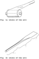
- a tube made of elastic material i.e. a material with a high yield strength, e.g. spring steel, which after straightening and winding on a drum has small size and mass. Being drawn it returns to its nominal form in which it was hardened. In this way, after unwinding the strip from the drum a structure constituting a thin-walled tube reappears, which is characterised by very advantageous flexural strength to mass ratio.
- a disadvantage of this construction is that the strip is vulnerable to damage due to loads transferred by region II, as shown in Fig.
- a significant portion of the drilling systems mass is due to a head pressing system, which has to be long, stiff and allow to transfer heavy loads, in the range of 100°N to 500°N.
- loads acting along the axis of the wellbore exceed the durability of typical coiled strip constructions. It is commonly known to those skilled in the art, that coiled strip tubes subjected to such loads become damaged in the transition region.
- the aim of the invention is to provide a possibility to reduce the mass of a drill system providing the possibility to easily introduce into a wellbore being drilled a casing tube, which protects the wellbore against being filled up in transition through loose layers.
- the aim of the invention is achieved by providing a drill head driving system, as defined in the independent claim 1, for a drill bit to drill a wellbore, wherein the drill head driving system is provided with a drill head (9) for mounting with the drill bit (8); a pressing mechanism (2) for applying a pressing force directed down the wellbore, characterised in that the drill head driving system comprises a first coiled tube (1) being coiled from a first strip (T1) wound on a first drum (B1) and fed into the wellbore, wherein an end of the first coiled tube (1) is attached to the drill head (9); a tube clamping mechanism (11) arranged in the upper portion of the first coiled tube (1) in a section of the first strip (T1) which is already coiled into the first coiled tube (1); wherein the pressing mechanism (2) is for transferring the pressing force to the tube clamping mechanism (11), the tube clamping mechanism (11) transfers the force to the section of the first strip (T1) which is already coiled into the first coiled tube (1), and via the
- the aim of the invention is also achieved by the application of a method of drilling, as defined in the independent claim 5, a wellbore, wherein a drill head (9) and a drill bit (8) mounted on the drill head (9) are lowered down the wellbore and pressed against its bottom, simultaneously inserting a tube into the wellbore, characterised in that a first strip (T1) is unrolled from a first drum (T1) forming a first coiled tube (1) having the drill head (9) attached to its end; in the upper portion of the first coiled tube (1), in a section of the first strip (T1) which is already coiled into the first coiled tube (1), a tube clamping mechanism (11) is arranged, which is used to transfer a pressing force to the section of the first strip (T1) which is already coiled into the first coiled tube (1) directed down the wellbore, the pressing force being applied via a pressing mechanism (2), whereby the drill bit (8) is being pressed to the ground being drilled, via the drill head (9), a casing
- Elimination of heavy pressing systems allows to reduce the weight of the whole drilling system, wherein the drill head driving system or the method of drilling a wellbore according to the invention is used.
- the portion of the coiled tube not in use is stored in the form of a flat strip wound on a drum, therefore the application of coiled tubes as drill head driving system significantly reduces the volume of the system in comparison to known solutions, wherein connected steel tubes are used.
- the application of coiled tubes is less failure prone than currently known and applied solutions, because the change of the drilling depth requires only to rotate the drum on which the strip is located and does not require the application of any releasable interfaces between consecutive segments of the well path.
- Fig. 1 shows strips coiled into coiled tubes known in the state of the art
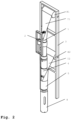
- Fig. 2 shows a drill head driving system
- Fig. 3a shows an interface between a casing tube and a first coiled tube responsible for movement of the drill head in a wellbore
- Fig. 3b shows schematically the operation of the interface
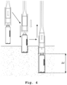
- Fig. 4 shows schematically an embodiment of the method of drilling according to the invention
- Fig. 5a shows a clamping mechanism, having a coiled tube and a securing band
- Fig. 5b shows the clamping mechanism without the securing band and the lower part of the coiled tube
- Fig. 6a shows the clamping mechanism with jaws in the inserted position
- Fig. 6b shows the clamping mechanism with jaws in the expanded position.
- FIG. la A coiled strip mechanism known in the state of the art is shown in Fig. la.
- Fig. la Experiments have proven that although the required head pressing force causes a deformation of the transition region II of the strip, shown in Fig. lb, the same force can be transferred without any damage by the section III of the strip after it has been completely coiled into a tube.
- the application of a clamping mechanism in a coiled tube makes it possible to use it simultaneously for two purposes: to provide protection of the wellbore against wall subsidence and to provide the head pressing force.
- the drill head driving system according to the invention has been shown in Fig. 2 .
- two coiled tubes have been used: a first coiled tube 1 and a casing tube 5.
- the first coiled tube 1 coiled from a strip T1 and the casing tube 5 coiled from a strip T2 are arranged coaxially, and the drums B1 and B2, on which the strips T1 and T2 are wound, respectively, are offset by 150 mm. This separation provides the possibility of free deployment of the strip T2 and change its profile from flat to C-shaped.
- the first coiled tube 1 is provided with a clamping mechanism 11, which is connected via an interface 13 accommodated in the opening of the first coiled tube 1, with a pressing mechanism 2 providing a force pressing the first coiled tube 1 in the direction down the wellbore.
- a drill head 9 is attached to an end of the first coiled tube 1.
- the free ends of the first coiled tube 1 and casing tube 5 are connected to each other via a unidirectional interface 15.
- This interface 15 transfers down the wellbore the pressing force applied via the end of the first coiled tube 1 to the end of the casing tube 5.
- a stimulated movement down the wellbore of the first coiled tube 1 causes also the casing tube 5 to move down the wellbore.
- the interface 15 disengages under the influence of the force exerted on the first coiled tube 1, directed up, to the outside of the wellbore. Thereby, it allows to pull out the drill head 9 and the first coiled tube 1 from the wellbore, while leaving in it the casing tube 5.
- the presence of the casing tube 5 prevent the walls of the wellbore from collapsing and enables pulling the drill head 9 out by winding the strip T1 coiled in the first coiled tube 1 back onto the drum Bl.
- the interface 15 shown in Fig. 3a is in charge of pulling the casing tube 5 formed from the strip T2, being drawn, down the wellbore as the first coiled tube 1 coiled from the strip T1 moves.
- the interface 15 essentially comprises two parts.
- the first element 6 of the interface 15 is attached to the to drill head 9, as shown in Fig. 3a and 3b .
- the first element 6 has its internal diameter less than the internal diameter of the casing tube 5.
- the second element 7 of the interface 15 is attached to the casing tube 5, as shown in Fig. 3a and 3b . Its external diameter is chosen so that during the movement of the drill head 9 down the wellbore the surface 'A' of the interface element 6 supports on the surface 'B' of the interface element 7. In this way a movement of the first coiled tube 1 down the drilled wellbore causes a force directed down the wellbore to be applied to the casing tube 5.
- the technical solution according to the invention can be simplified, by applying only the first coiled tube 1 without the casing tube 5, becoming in such a way the technical solution not according to the invention.
- the first coiled tube 1 acts as a casing tube after the drilling is complete.
- the drill bit 8 and the drill head 9 can be coupled permanently.
- the drill bit 8 can be a bit, a drill, or any other tool applicable in drilling holes known in the state of the art.
- the first coiling tube 1 is connected to the casing tube 5.
- the casing tube 5 is coiled from the strip T2 drawn from the second drum B2.
- the first coiled tube 1 and the casing tube 5 are connected via the interface 15 so that a movement of the first coiled tube 1 downwards is related to application of a force acting downwards the coiled tube 5, and in consequence drawing the strip T2 from the drum B2.
- Fig. 5a shows a clamping mechanism 11.
- the clamping mechanism 11 is almost completely located inside the first coiled tube 1 and is adapted to cooperate with means intended for exerting pressing force known in the state of the art. Outside of the first coiled tube 1 only a moulder 10 is located.
- the moulder diameter corresponds to the nominal external diameter of the first coiled tube 1.
- the moulder 10 prevents the first coiled tube 1 from buckling under the operation of the clamping mechanism 11.
- the clamping mechanism 11 is provided with at least two jaws 12.
- the jaws 12 are arranged inside the structure of the clamping mechanism 11 so that they could be pressed to the inner walls of the first coiled tube 1. Covering the surface of the jaws 12 contacting with the inside of the first coiled tube 1 with a material having a high static friction coefficient makes it possible to increase the maximal pressing force that the clamping mechanism 11 is able to transfer.
- the clamping mechanism 11 is also provided with a drive 14 adapted to press the jaws 12 outwards from the axis of the first coiled tube 1.
- the pressing mechanism 2 transfers the pressing force to the clamping mechanism 11, which transfers it to the section of the strip Tl, which is already coiled in the first coiled tube 1, and via the first coiled tube 1 to the drill head 9.
- the transition section II of the strip Tl does not participate in transferring the pressing force.
- the application as the first coiled tube 1 of the strip T1 coiled into a partially open tube allows for an easier attachment of the clamping mechanism 11 to the pressing mechanism 2 providing the longitudinal force. In this situation it is sufficient to apply only an interface 13 moveable inside the opening of the first coiled tube 1. By means of the interface 13 the pressing mechanism 2 moves down the wellbore.
- the drill head 9 drilling the wellbore is being pressed to the bottom of the wellbore by means of the first coiled tube 1 coiled from the strip T1 drawn from the drum B1.
- the pressing force is applied to the first coiled tube 1 by means of the pressing mechanism 2 attached to any mechanism known in the state of the art which is suitable for jamming on a thin-walled tube.
- the drill head 9 remains at the bottom of the wellbore, and the first coiled tube 1 secures its walls.
- a person skilled in the art could propose numerous mechanisms and methods allowing to disengage the first coiled tube 1 and the drill head 9 after completion of the drilling and pull it out, e.g. by means of a string.
Landscapes
- Engineering & Computer Science (AREA)
- Geology (AREA)
- Life Sciences & Earth Sciences (AREA)
- Mining & Mineral Resources (AREA)
- Environmental & Geological Engineering (AREA)
- Fluid Mechanics (AREA)
- Physics & Mathematics (AREA)
- General Life Sciences & Earth Sciences (AREA)
- Geochemistry & Mineralogy (AREA)
- Mechanical Engineering (AREA)
- Earth Drilling (AREA)
- Perforating, Stamping-Out Or Severing By Means Other Than Cutting (AREA)
- Drilling And Boring (AREA)
Claims (8)
- Bohrkopfantriebssystem für eine Bohrkrone (8) zum Bohren eines Bohrlochs, wobei das Bohrkopfantriebssystem miteinem Bohrkopf (9) zur Montage mit der Bohrkrone (8);einem Pressmechanismus (2) zum Aufbringen einer nach unten in das Bohrloch gerichteten Presskraft, versehen ist;dadurch gekennzeichnet, dassdas Bohrkopfantriebssystem Folgendes umfassteine erste Rohrwendel (1), die von einem ersten Streifen (T1) gewickelt ist, der auf eine erste Trommel (B1) aufgewickelt ist und in das Bohrloch eingeführt wird, wobei ein Ende der ersten Rohrwendel (1) an dem Bohrkopf (9) befestigt ist;einen Rohrklemmmechanismus (11), der im oberen Teil der ersten Rohrwendel (1) in einem Abschnitt des ersten Streifens (Tl) angeordnet ist, der bereits in die erste Rohrwendel (1) eingewickelt ist;wobei der Pressmechanismus (2) zur Übertragung der Presskraft auf den Rohrklemmmechanismus (11) dient, der Rohrklemmmechanismus (11) die Kraft auf den Abschnitt des ersten Streifens (Tl), der bereits in die erste Rohrwendel (1) eingewickelt ist, und über die erste Rohrwendel (1) auf den Bohrkopf (9) überträgt;wobei die erste Rohrwendel (1) teilweise offen ist und die Verbindung zwischen dem Rohrklemmmechanismus (11) und dem Pressmechanismus (2) eine erste Schnittstelle (13) bildet, die erste Schnittstelle (13) in der Öffnung der ersten Rohrwendel (1) beweglich ist unddas System ferner ein Bohrrohr (5) umfasst, das aus einem zweiten Streifen (T2) gewickelt ist, der von einer zweiten Trommel (B2) abgewickelt wird,wobei die erste Rohrwendel (1) und das Bohrrohr (5) im Wesentlichen koaxial sind und der Durchmesser des Bohrrohrs (5) größer ist als der Durchmesser der ersten Rohrwendel (1),wobei die Enden der ersten Rohrwendel (1) und des Bohrrohrs (5) über eine zweite Schnittstelle (15) miteinander zusammenwirken, wobei die zweite Schnittstelle (15) die von der ersten Trommel (T1) ausgehende Kraft überträgt, wobei die Kraft von dem Ende der ersten Rohrwendel (1) auf das Ende des Bohrrohrs (5) ausgeübt wird,
wobei die zweite Schnittstelle (15) ein erstes Element (6), das mit dem Bohrkopf (9) verbunden ist, und ein zweites Element (7) umfasst, das mit dem unteren Ende des Bohrrohrs (5) verbunden und innerhalb des Bohrrohrs (5) angeordnet ist, wobei die zweite Schnittstelle (15) unter einer in Richtung einer Oberfläche gerichteten Kraft, die auf das erste Element (6) ausgeübt wird, lösbar ist. - System nach Anspruch 1, dadurch gekennzeichnet, dass der Rohrklemmmechanismus (11) mit einem Band (10) und Spannmitteln (12, 14) versehen ist, wobei das Band (10) außerhalb der ersten Rohrwendel (1) und die Spannmittel (12, 14) innerhalb der ersten Rohrwendel (1) angeordnet sind.
- System nach Anspruch 2, dadurch gekennzeichnet, dass die Spannmittel (12, 14) aus Klemmbacken (12) und einem Antrieb (14) bestehen, der die Klemmbacken (12) an die Innenwand der ersten Rohrwendel (1) drückt.
- System nach Anspruch 3, dadurch gekennzeichnet, dass die Klemmbacken (12) mit einem Material überzogen sind, das einen hohen Haftreibungskoeffizienten an den Oberflächen aufweist, die die Wände der ersten Rohrwendel (1) berühren.
- Verfahren zum Bohren eines Bohrlochs, bei dem ein Bohrkopf (9) und eine auf dem Bohrkopf (9) montierte Bohrkrone (8) in das Bohrloch abgesenkt und gegen dessen Boden gedrückt werden, wobei gleichzeitig ein Rohr in das Bohrloch eingeführt wird,
dadurch gekennzeichnet, dassein erster Streifen (Tl) von einer ersten Trommel (Tl) abgerollt wird, die eine erste Rohrwendel (1) bildet, an deren Ende der Bohrkopf (9) befestigt ist;im oberen Bereich der ersten Rohrwendel (1) in einem bereits in die erste Rohrwendel (1) eingewickelten Abschnitt des ersten Streifens (Tl) ein Rohrklemmmechanismus (11) angeordnet ist, der dazu dient, eine Presskraft auf den bereits in die erste Rohrwendel (1) eingewickelten Abschnitt des ersten Streifens (Tl) in Richtung des Bohrloches zu übertragen, wobei die Presskraft über einen Pressmechanismus (2) aufgebracht wird, wodurch die Bohrkrone (8) über den Bohrkopf (9) an den zu bohrenden Boden gepresst wird,ein Bohrrohr (5), das von einem zweiten Streifen (T2) gewickelt wird, der von der zweiten Trommel (B2) abgezogen wird, mit der ersten Rohrwendel (1) verbunden ist, wobei ein Ende des Bohrrohrs (5) mit einem Ende der ersten Rohrwendel (1) mittels einer zweiten Schnittstelle (15) verbunden ist, die die vom Ende der ersten Rohrwendel (1) ausgeübte, in das Bohrloch gerichtete Kraft auf das Ende des Bohrrohrs (5) überträgt,
wobei die zweite Schnittstelle (15) ein erstes Element (6), das mit dem Bohrkopf (9) verbunden ist und ein zweites Element (7) umfasst, das mit dem unteren Ende des Bohrrohrs (5) innerhalb des Bohrrohrs (5) verbunden ist und unter einer auf eine Oberfläche gerichteten Kraft, die auf das erste Element (6) ausgeübt wird, lösbar ist,wobei eine stimulierte Bewegung der ersten Rohrwendel (1) im Bohrloch nach unten bewirkt, dass sich auch das Bohrrohr (5) im Bohrloch nach unten bewegt. - Verfahren nach Anspruch 5, dadurch gekennzeichnet, dass der Rohrklemmmechanismus (11) mit einem Band (10) und Spannmitteln (12, 14) versehen ist, wobei das Band (10) außerhalb der ersten Rohrwendel (1) und die Spannmittel (12, 14) innerhalb der ersten Rohrwendel (1) angeordnet sind.
- Verfahren nach Anspruch 6, dadurch gekennzeichnet, dass die Spannmittel (12, 14) aus Klemmbacken (12) und einem Antrieb (14) bestehen, der die Klemmbacken (12) an die Innenwand der ersten Rohrwendel (1) drückt.
- Verfahren nach Anspruch 7, dadurch gekennzeichnet, dass die Klemmbacken (12) mit einem Material überzogen sind, das einen hohen Haftreibungskoeffizienten an den Oberflächen aufweist, die die Wände der ersten Rohrwendel (1) berühren.
Applications Claiming Priority (2)
| Application Number | Priority Date | Filing Date | Title |
|---|---|---|---|
| PL406633A PL224322B1 (pl) | 2013-12-23 | 2013-12-23 | Układ prowadzenia głowicy wiercącej, mechanizm rozporowy oraz sposób wiercenia |
| PCT/IB2014/065537 WO2015097575A2 (en) | 2013-12-23 | 2014-10-22 | Drilling head driving device, spragging mechanism and drilling method |
Publications (3)
| Publication Number | Publication Date |
|---|---|
| EP3087244A2 EP3087244A2 (de) | 2016-11-02 |
| EP3087244C0 EP3087244C0 (de) | 2023-07-19 |
| EP3087244B1 true EP3087244B1 (de) | 2023-07-19 |
Family
ID=52014176
Family Applications (1)
| Application Number | Title | Priority Date | Filing Date |
|---|---|---|---|
| EP14809110.1A Active EP3087244B1 (de) | 2013-12-23 | 2014-10-22 | System zum formen eines rohres aus einem auf einer trommel aufgerollten flachen streifen und bohrverfahren |
Country Status (4)
| Country | Link |
|---|---|
| US (1) | US9995096B2 (de) |
| EP (1) | EP3087244B1 (de) |
| PL (1) | PL224322B1 (de) |
| WO (1) | WO2015097575A2 (de) |
Families Citing this family (3)
| Publication number | Priority date | Publication date | Assignee | Title |
|---|---|---|---|---|
| IT201600073812A1 (it) * | 2016-07-14 | 2018-01-14 | Eni Spa | Dispositivo e metodo di messa in opera di una struttura tubolare riformabile in materiale composito. |
| NO345937B1 (en) * | 2018-02-14 | 2021-11-01 | Sintef Tto As | A method and apparatus for simultaneously drilling and in-situ casing installation |
| CA3158178A1 (en) | 2019-10-30 | 2021-05-06 | Aqirian Technology Pty Ltd | A method and apparatus for drilling and positioning a collar support sleeve into a blast hole |
Family Cites Families (13)
| Publication number | Priority date | Publication date | Assignee | Title |
|---|---|---|---|---|
| GB644516A (en) * | 1948-04-22 | 1950-10-11 | Dunlop Rubber Co | Improvements relating to flexible tubular structures made of thermoplastic material |
| US2934130A (en) * | 1955-12-20 | 1960-04-26 | Liqua Pak Inc | Apparatus for forming a round tube from flat sheet material |
| US4108258A (en) | 1976-07-21 | 1978-08-22 | Atlas Copco Aktiebolag | Rock drilling apparatus with noise reducing drill rod cover |
| US4154310A (en) | 1976-09-27 | 1979-05-15 | Konstantinovsky Miron S | Method and equipment for drilling wells |
| NL183836C (nl) * | 1976-11-24 | 1989-02-01 | Berg A P Ingbureau | Inrichting voor het vormen en in de grond drukken van een stijve buis, gevormd uit oprolbare stroken van veerkrachtig, buigzaam materiaal. |
| US5154310A (en) | 1989-02-10 | 1992-10-13 | Axia, Inc. | End nesting stackable container modified to maintain material firmly in place |
| US5169264A (en) | 1990-04-05 | 1992-12-08 | Kidoh Technical Ins. Co., Ltd. | Propulsion process of buried pipe |
| FI109429B (fi) | 1998-11-09 | 2002-07-31 | Uponor Innovation Ab | Menetelmä putken tekemiseksi ja putki |
| DE102007008373A1 (de) * | 2007-02-16 | 2008-08-28 | Notar, Walter | Verfahren und Einrichtung zur Erzeugung von tiefen Bohrungen |
| GB2455285B (en) | 2007-11-22 | 2012-05-09 | Schlumberger Holdings | Formation of flow conduits under pressure |
| US20110265941A1 (en) | 2010-04-29 | 2011-11-03 | Baker Hughes Incorporated | On Site Manufactured Self Expanding Tubulars and Method |
| EP2502725B1 (de) | 2011-03-24 | 2015-01-07 | PackSys Global (Switzerland) Ltd. | Vorrichtung und Verfahren zum Herstellen von Tubenkörpern |
| DE102011001547A1 (de) * | 2011-03-24 | 2012-09-27 | Packsys Global (Switzerland) Ltd. | Vorrichtung zum Herstellen von Tubenkörpern |
-
2013
- 2013-12-23 PL PL406633A patent/PL224322B1/pl unknown
-
2014
- 2014-10-22 US US14/779,381 patent/US9995096B2/en active Active
- 2014-10-22 EP EP14809110.1A patent/EP3087244B1/de active Active
- 2014-10-22 WO PCT/IB2014/065537 patent/WO2015097575A2/en not_active Ceased
Also Published As
| Publication number | Publication date |
|---|---|
| US20160047182A1 (en) | 2016-02-18 |
| PL406633A1 (pl) | 2015-07-06 |
| PL224322B1 (pl) | 2016-12-30 |
| EP3087244C0 (de) | 2023-07-19 |
| WO2015097575A2 (en) | 2015-07-02 |
| US9995096B2 (en) | 2018-06-12 |
| EP3087244A2 (de) | 2016-11-02 |
| WO2015097575A3 (en) | 2016-01-14 |
Similar Documents
| Publication | Publication Date | Title |
|---|---|---|
| CA2882345C (en) | Wellbore anchoring system | |
| EP2169177B1 (de) | Glattrohrsperre für eine rückziehbare Aufnahmeverlängerung | |
| WO2016209686A1 (en) | Millable bit to whipstock connector | |
| US20120090894A1 (en) | Locking device for a drilling device | |
| US9988869B2 (en) | Jarring using controllable powered bidirectional mechanical jar | |
| EP3087244B1 (de) | System zum formen eines rohres aus einem auf einer trommel aufgerollten flachen streifen und bohrverfahren | |
| US20160251945A1 (en) | Running tool and liner hanger contingency release mechanism | |
| US20050051342A1 (en) | Liner running system and method | |
| CA2504578C (en) | Force transfer apparatus to assist release of loaded member | |
| US11162313B2 (en) | Anchor for a downhole linear actuator | |
| US20180156003A1 (en) | Downhole impact apparatus | |
| US9938787B2 (en) | Fully supported c-ring slip retention system | |
| EP3563034B1 (de) | Bohrlochwerkzeug mit einem drehgelenk | |
| US11332988B2 (en) | Traversing across a wash-out zone in a wellbore | |
| EP3390766B1 (de) | Im bohrloch expandierbare rohrförmige elemente mit abgedichteter lösbarer verbindung | |
| US10781650B2 (en) | Downhole tool with multi-stage anchoring | |
| EP3788235B1 (de) | Selbstbohrender hybrid-felsenanker | |
| DE112011103199B4 (de) | Vorrichtung und Verfahren zum Bohren von Bohrlöchern | |
| POLSKIEJ et al. | III III a IIOI DID III OII 100 II0 II0 II0 III 0II 101 olio II uii IIi | |
| US10400532B2 (en) | Downhole tool anchoring device |
Legal Events
| Date | Code | Title | Description |
|---|---|---|---|
| PUAI | Public reference made under article 153(3) epc to a published international application that has entered the european phase |
Free format text: ORIGINAL CODE: 0009012 |
|
| 17P | Request for examination filed |
Effective date: 20150924 |
|
| AK | Designated contracting states |
Kind code of ref document: A2 Designated state(s): AL AT BE BG CH CY CZ DE DK EE ES FI FR GB GR HR HU IE IS IT LI LT LU LV MC MK MT NL NO PL PT RO RS SE SI SK SM TR |
|
| AX | Request for extension of the european patent |
Extension state: BA ME |
|
| DAX | Request for extension of the european patent (deleted) | ||
| STAA | Information on the status of an ep patent application or granted ep patent |
Free format text: STATUS: EXAMINATION IS IN PROGRESS |
|
| 17Q | First examination report despatched |
Effective date: 20210519 |
|
| GRAP | Despatch of communication of intention to grant a patent |
Free format text: ORIGINAL CODE: EPIDOSNIGR1 |
|
| STAA | Information on the status of an ep patent application or granted ep patent |
Free format text: STATUS: GRANT OF PATENT IS INTENDED |
|
| INTG | Intention to grant announced |
Effective date: 20230215 |
|
| GRAS | Grant fee paid |
Free format text: ORIGINAL CODE: EPIDOSNIGR3 |
|
| GRAA | (expected) grant |
Free format text: ORIGINAL CODE: 0009210 |
|
| STAA | Information on the status of an ep patent application or granted ep patent |
Free format text: STATUS: THE PATENT HAS BEEN GRANTED |
|
| AK | Designated contracting states |
Kind code of ref document: B1 Designated state(s): AL AT BE BG CH CY CZ DE DK EE ES FI FR GB GR HR HU IE IS IT LI LT LU LV MC MK MT NL NO PL PT RO RS SE SI SK SM TR |
|
| REG | Reference to a national code |
Ref country code: GB Ref legal event code: FG4D |
|
| REG | Reference to a national code |
Ref country code: CH Ref legal event code: EP |
|
| REG | Reference to a national code |
Ref country code: DE Ref legal event code: R096 Ref document number: 602014087692 Country of ref document: DE |
|
| REG | Reference to a national code |
Ref country code: IE Ref legal event code: FG4D |
|
| U01 | Request for unitary effect filed |
Effective date: 20230817 |
|
| U07 | Unitary effect registered |
Designated state(s): AT BE BG DE DK EE FI FR IT LT LU LV MT NL PT SE SI Effective date: 20230823 |
|
| REG | Reference to a national code |
Ref country code: LT Ref legal event code: MG9D |
|
| U20 | Renewal fee for the european patent with unitary effect paid |
Year of fee payment: 10 Effective date: 20231027 |
|
| PG25 | Lapsed in a contracting state [announced via postgrant information from national office to epo] |
Ref country code: GR Free format text: LAPSE BECAUSE OF FAILURE TO SUBMIT A TRANSLATION OF THE DESCRIPTION OR TO PAY THE FEE WITHIN THE PRESCRIBED TIME-LIMIT Effective date: 20231020 |
|
| PG25 | Lapsed in a contracting state [announced via postgrant information from national office to epo] |
Ref country code: IS Free format text: LAPSE BECAUSE OF FAILURE TO SUBMIT A TRANSLATION OF THE DESCRIPTION OR TO PAY THE FEE WITHIN THE PRESCRIBED TIME-LIMIT Effective date: 20231119 |
|
| PG25 | Lapsed in a contracting state [announced via postgrant information from national office to epo] |
Ref country code: RS Free format text: LAPSE BECAUSE OF FAILURE TO SUBMIT A TRANSLATION OF THE DESCRIPTION OR TO PAY THE FEE WITHIN THE PRESCRIBED TIME-LIMIT Effective date: 20230719 Ref country code: NO Free format text: LAPSE BECAUSE OF FAILURE TO SUBMIT A TRANSLATION OF THE DESCRIPTION OR TO PAY THE FEE WITHIN THE PRESCRIBED TIME-LIMIT Effective date: 20231019 Ref country code: IS Free format text: LAPSE BECAUSE OF FAILURE TO SUBMIT A TRANSLATION OF THE DESCRIPTION OR TO PAY THE FEE WITHIN THE PRESCRIBED TIME-LIMIT Effective date: 20231119 Ref country code: HR Free format text: LAPSE BECAUSE OF FAILURE TO SUBMIT A TRANSLATION OF THE DESCRIPTION OR TO PAY THE FEE WITHIN THE PRESCRIBED TIME-LIMIT Effective date: 20230719 Ref country code: GR Free format text: LAPSE BECAUSE OF FAILURE TO SUBMIT A TRANSLATION OF THE DESCRIPTION OR TO PAY THE FEE WITHIN THE PRESCRIBED TIME-LIMIT Effective date: 20231020 |
|
| PG25 | Lapsed in a contracting state [announced via postgrant information from national office to epo] |
Ref country code: PL Free format text: LAPSE BECAUSE OF FAILURE TO SUBMIT A TRANSLATION OF THE DESCRIPTION OR TO PAY THE FEE WITHIN THE PRESCRIBED TIME-LIMIT Effective date: 20230719 |
|
| REG | Reference to a national code |
Ref country code: DE Ref legal event code: R097 Ref document number: 602014087692 Country of ref document: DE |
|
| PG25 | Lapsed in a contracting state [announced via postgrant information from national office to epo] |
Ref country code: ES Free format text: LAPSE BECAUSE OF FAILURE TO SUBMIT A TRANSLATION OF THE DESCRIPTION OR TO PAY THE FEE WITHIN THE PRESCRIBED TIME-LIMIT Effective date: 20230719 |
|
| PG25 | Lapsed in a contracting state [announced via postgrant information from national office to epo] |
Ref country code: SM Free format text: LAPSE BECAUSE OF FAILURE TO SUBMIT A TRANSLATION OF THE DESCRIPTION OR TO PAY THE FEE WITHIN THE PRESCRIBED TIME-LIMIT Effective date: 20230719 Ref country code: RO Free format text: LAPSE BECAUSE OF FAILURE TO SUBMIT A TRANSLATION OF THE DESCRIPTION OR TO PAY THE FEE WITHIN THE PRESCRIBED TIME-LIMIT Effective date: 20230719 Ref country code: ES Free format text: LAPSE BECAUSE OF FAILURE TO SUBMIT A TRANSLATION OF THE DESCRIPTION OR TO PAY THE FEE WITHIN THE PRESCRIBED TIME-LIMIT Effective date: 20230719 Ref country code: CZ Free format text: LAPSE BECAUSE OF FAILURE TO SUBMIT A TRANSLATION OF THE DESCRIPTION OR TO PAY THE FEE WITHIN THE PRESCRIBED TIME-LIMIT Effective date: 20230719 Ref country code: SK Free format text: LAPSE BECAUSE OF FAILURE TO SUBMIT A TRANSLATION OF THE DESCRIPTION OR TO PAY THE FEE WITHIN THE PRESCRIBED TIME-LIMIT Effective date: 20230719 |
|
| PLBE | No opposition filed within time limit |
Free format text: ORIGINAL CODE: 0009261 |
|
| STAA | Information on the status of an ep patent application or granted ep patent |
Free format text: STATUS: NO OPPOSITION FILED WITHIN TIME LIMIT |
|
| PG25 | Lapsed in a contracting state [announced via postgrant information from national office to epo] |
Ref country code: MC Free format text: LAPSE BECAUSE OF FAILURE TO SUBMIT A TRANSLATION OF THE DESCRIPTION OR TO PAY THE FEE WITHIN THE PRESCRIBED TIME-LIMIT Effective date: 20230719 |
|
| REG | Reference to a national code |
Ref country code: CH Ref legal event code: PL |
|
| 26N | No opposition filed |
Effective date: 20240422 |
|
| GBPC | Gb: european patent ceased through non-payment of renewal fee |
Effective date: 20231022 |
|
| PG25 | Lapsed in a contracting state [announced via postgrant information from national office to epo] |
Ref country code: GB Free format text: LAPSE BECAUSE OF NON-PAYMENT OF DUE FEES Effective date: 20231022 |
|
| PG25 | Lapsed in a contracting state [announced via postgrant information from national office to epo] |
Ref country code: CH Free format text: LAPSE BECAUSE OF NON-PAYMENT OF DUE FEES Effective date: 20231031 |
|
| PG25 | Lapsed in a contracting state [announced via postgrant information from national office to epo] |
Ref country code: GB Free format text: LAPSE BECAUSE OF NON-PAYMENT OF DUE FEES Effective date: 20231022 Ref country code: CH Free format text: LAPSE BECAUSE OF NON-PAYMENT OF DUE FEES Effective date: 20231031 |
|
| PG25 | Lapsed in a contracting state [announced via postgrant information from national office to epo] |
Ref country code: IE Free format text: LAPSE BECAUSE OF NON-PAYMENT OF DUE FEES Effective date: 20231022 |
|
| PG25 | Lapsed in a contracting state [announced via postgrant information from national office to epo] |
Ref country code: IE Free format text: LAPSE BECAUSE OF NON-PAYMENT OF DUE FEES Effective date: 20231022 |
|
| U20 | Renewal fee for the european patent with unitary effect paid |
Year of fee payment: 11 Effective date: 20241011 |
|
| PG25 | Lapsed in a contracting state [announced via postgrant information from national office to epo] |
Ref country code: CY Free format text: LAPSE BECAUSE OF FAILURE TO SUBMIT A TRANSLATION OF THE DESCRIPTION OR TO PAY THE FEE WITHIN THE PRESCRIBED TIME-LIMIT; INVALID AB INITIO Effective date: 20141022 |
|
| PG25 | Lapsed in a contracting state [announced via postgrant information from national office to epo] |
Ref country code: HU Free format text: LAPSE BECAUSE OF FAILURE TO SUBMIT A TRANSLATION OF THE DESCRIPTION OR TO PAY THE FEE WITHIN THE PRESCRIBED TIME-LIMIT; INVALID AB INITIO Effective date: 20141022 |
|
| PG25 | Lapsed in a contracting state [announced via postgrant information from national office to epo] |
Ref country code: TR Free format text: LAPSE BECAUSE OF FAILURE TO SUBMIT A TRANSLATION OF THE DESCRIPTION OR TO PAY THE FEE WITHIN THE PRESCRIBED TIME-LIMIT Effective date: 20230719 |