EP3086722B1 - Coupling features for ultrasonic surgical instrument - Google Patents
Coupling features for ultrasonic surgical instrument Download PDFInfo
- Publication number
- EP3086722B1 EP3086722B1 EP14831133.5A EP14831133A EP3086722B1 EP 3086722 B1 EP3086722 B1 EP 3086722B1 EP 14831133 A EP14831133 A EP 14831133A EP 3086722 B1 EP3086722 B1 EP 3086722B1
- Authority
- EP
- European Patent Office
- Prior art keywords
- assembly
- transducer
- motor
- shaft assembly
- waveguide
- Prior art date
- Legal status (The legal status is an assumption and is not a legal conclusion. Google has not performed a legal analysis and makes no representation as to the accuracy of the status listed.)
- Active
Links
Images


Classifications
-
- A—HUMAN NECESSITIES
- A61—MEDICAL OR VETERINARY SCIENCE; HYGIENE
- A61B—DIAGNOSIS; SURGERY; IDENTIFICATION
- A61B17/00—Surgical instruments, devices or methods
- A61B17/32—Surgical cutting instruments
- A61B17/320068—Surgical cutting instruments using mechanical vibrations, e.g. ultrasonic
-
- A—HUMAN NECESSITIES
- A61—MEDICAL OR VETERINARY SCIENCE; HYGIENE
- A61B—DIAGNOSIS; SURGERY; IDENTIFICATION
- A61B17/00—Surgical instruments, devices or methods
- A61B17/32—Surgical cutting instruments
- A61B17/320068—Surgical cutting instruments using mechanical vibrations, e.g. ultrasonic
- A61B17/320092—Surgical cutting instruments using mechanical vibrations, e.g. ultrasonic with additional movable means for clamping or cutting tissue, e.g. with a pivoting jaw
-
- A—HUMAN NECESSITIES
- A61—MEDICAL OR VETERINARY SCIENCE; HYGIENE
- A61B—DIAGNOSIS; SURGERY; IDENTIFICATION
- A61B17/00—Surgical instruments, devices or methods
- A61B2017/0046—Surgical instruments, devices or methods with a releasable handle; with handle and operating part separable
-
- A—HUMAN NECESSITIES
- A61—MEDICAL OR VETERINARY SCIENCE; HYGIENE
- A61B—DIAGNOSIS; SURGERY; IDENTIFICATION
- A61B17/00—Surgical instruments, devices or methods
- A61B2017/0046—Surgical instruments, devices or methods with a releasable handle; with handle and operating part separable
- A61B2017/00473—Distal part, e.g. tip or head
-
- A—HUMAN NECESSITIES
- A61—MEDICAL OR VETERINARY SCIENCE; HYGIENE
- A61B—DIAGNOSIS; SURGERY; IDENTIFICATION
- A61B17/00—Surgical instruments, devices or methods
- A61B2017/00477—Coupling
-
- A—HUMAN NECESSITIES
- A61—MEDICAL OR VETERINARY SCIENCE; HYGIENE
- A61B—DIAGNOSIS; SURGERY; IDENTIFICATION
- A61B17/00—Surgical instruments, devices or methods
- A61B17/32—Surgical cutting instruments
- A61B17/320068—Surgical cutting instruments using mechanical vibrations, e.g. ultrasonic
- A61B2017/320071—Surgical cutting instruments using mechanical vibrations, e.g. ultrasonic with articulating means for working tip
-
- A—HUMAN NECESSITIES
- A61—MEDICAL OR VETERINARY SCIENCE; HYGIENE
- A61B—DIAGNOSIS; SURGERY; IDENTIFICATION
- A61B17/00—Surgical instruments, devices or methods
- A61B17/32—Surgical cutting instruments
- A61B17/320068—Surgical cutting instruments using mechanical vibrations, e.g. ultrasonic
- A61B2017/320089—Surgical cutting instruments using mechanical vibrations, e.g. ultrasonic node location
-
- A—HUMAN NECESSITIES
- A61—MEDICAL OR VETERINARY SCIENCE; HYGIENE
- A61B—DIAGNOSIS; SURGERY; IDENTIFICATION
- A61B17/00—Surgical instruments, devices or methods
- A61B17/32—Surgical cutting instruments
- A61B17/320068—Surgical cutting instruments using mechanical vibrations, e.g. ultrasonic
- A61B17/320092—Surgical cutting instruments using mechanical vibrations, e.g. ultrasonic with additional movable means for clamping or cutting tissue, e.g. with a pivoting jaw
- A61B2017/320093—Surgical cutting instruments using mechanical vibrations, e.g. ultrasonic with additional movable means for clamping or cutting tissue, e.g. with a pivoting jaw additional movable means performing cutting operation
-
- A—HUMAN NECESSITIES
- A61—MEDICAL OR VETERINARY SCIENCE; HYGIENE
- A61B—DIAGNOSIS; SURGERY; IDENTIFICATION
- A61B17/00—Surgical instruments, devices or methods
- A61B17/32—Surgical cutting instruments
- A61B17/320068—Surgical cutting instruments using mechanical vibrations, e.g. ultrasonic
- A61B17/320092—Surgical cutting instruments using mechanical vibrations, e.g. ultrasonic with additional movable means for clamping or cutting tissue, e.g. with a pivoting jaw
- A61B2017/320094—Surgical cutting instruments using mechanical vibrations, e.g. ultrasonic with additional movable means for clamping or cutting tissue, e.g. with a pivoting jaw additional movable means performing clamping operation
-
- A—HUMAN NECESSITIES
- A61—MEDICAL OR VETERINARY SCIENCE; HYGIENE
- A61B—DIAGNOSIS; SURGERY; IDENTIFICATION
- A61B90/00—Instruments, implements or accessories specially adapted for surgery or diagnosis and not covered by any of the groups A61B1/00 - A61B50/00, e.g. for luxation treatment or for protecting wound edges
- A61B90/03—Automatic limiting or abutting means, e.g. for safety
- A61B2090/031—Automatic limiting or abutting means, e.g. for safety torque limiting
Definitions
- a variety of surgical instruments include an end effector having a blade element that vibrates at ultrasonic frequencies to cut and/or seal tissue (e.g., by denaturing proteins in tissue cells). These instruments include piezoelectric elements that convert electrical power into ultrasonic vibrations, which are communicated along an acoustic waveguide to the blade element. The precision of cutting and coagulation may be controlled by the surgeon's technique and adjusting the power level, blade edge, tissue traction and blade pressure
- Known US Pat. No 2013/0324998 entitled "Loading Cartridge for Surgical Instrument End Effector” discloses an exemplary surgical instrument including a body assembly and a selectively coupleable end effector assembly wherein a motor is used to couple the transmission assembly and transducer.
- ultrasonic surgical instruments examples include the HARMONIC ACE® Ultrasonic Shears, the HARMONIC WAVE® Ultrasonic Shears, the HARMONIC FOCUS® Ultrasonic Shears, and the HARMONIC SYNERGY® Ultrasonic Blades, all by Ethicon Endo-Surgery, Inc. of Cincinnati, Ohio. Further examples of such devices and related concepts are disclosed in U.S. Pat. No. 5,322,055 , entitled “Clamp Coagulator/Cutting System for Ultrasonic Surgical Instruments," issued June 21, 1994; U.S. Pat. No.
- ultrasonic surgical instruments may include a cordless transducer such as that disclosed in U.S. Pub. No. 2012/0112687 , entitled “Recharge System for Medical Devices,” published May 10, 2012; U.S. Pub. No. 2012/0116265 , entitled “Surgical Instrument with Charging Devices,” published May 10, 2012; and/or U.S. Pat. App. No. 61/410,603, filed November 5, 2010 , entitled “Energy-Based Surgical Instruments,"
- ultrasonic surgical instruments may include an articulating shaft section. Examples of such ultrasonic surgical instruments are disclosed in U.S. Pat. App. No. 13/538,588, filed June 29, 2012 , entitled “Surgical Instruments with Articulating Shafts," ; and U.S. Pat. App. No. 13/657,553, filed October 22, 2012 , entitled “Flexible Harmonic Waveguides/Blades for Surgical Instruments,”.
- proximal and distal are defined herein relative to a human or robotic operator of the surgical instrument.
- proximal refers the position of an element closer to the human or robotic operator of the surgical instrument and further away from the surgical end effector of the surgical instrument.
- distal refers to the position of an element closer to the surgical end effector of the surgical instrument and further away from the human or robotic operator of the surgical instrument.
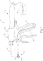
- FIG. 1 illustrates an exemplary ultrasonic surgical instrument (10). At least part of instrument (10) may be constructed and operable in accordance with at least some of the teachings of U.S. Pat. No. 5,322,055 ; U.S. Pat. No. 5,873,873 ; U.S. Pat. No. 5,980,510 ; U.S. Pat. No. 6,325,811 ; U.S. Pat. No. 6,773,444 ; U.S. Pat. No. 6,783,524 ; U.S. Pub. No. 2006/0079874 ; U.S. Pub. No. 2007/0191713 ; U.S. Pub. No. 2007/0282333 ; U.S. Pub. No.
- instrument (10) is operable to cut tissue and seal or weld tissue (e.g., a blood vessel, etc.) substantially simultaneously. It should also be understood that instrument (10) may have various structural and functional similarities with the HARMONIC ACE® Ultrasonic Shears, the HARMONIC WAVE® Ultrasonic Shears, the HARMONIC FOCUS® Ultrasonic Shears, and/or the HARMONIC SYNERGY® Ultrasonic Blades. Furthermore, instrument (10) may have various structural and functional similarities with the devices taught in any of the other references that are cited.
- Instrument (10) of the present example comprises a handle assembly (20), a shaft assembly (30), and an end effector (40).
- shaft assembly (30) comprises an outer sheath (32), an inner tube (34) slidably disposed within outer sheath (32), and a waveguide (102) disposed within inner tube (34).
- longitudinal translation of inner tube (34) causes actuation of clamp arm (44) at end effector (40).
- Handle assembly (20) comprises a body (22) including a pistol grip (24) and a pair of buttons (26).
- Handle assembly (20) also includes a trigger (28) that is pivotable toward and away from pistol grip (24).
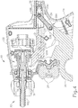
- trigger (28) is pivotably coupled to handle assembly (20) via a pin (23A) such that trigger (28) rotates about an axis located below shaft assembly (30).
- Trigger (28) is coupled with a yoke (25) via a linkage (29) such that rotation of trigger (28) about pin (23A) causes longitudinal translation of yoke (25).
- a first end (29A) of linkage (29) is rotatably coupled with a proximal portion of trigger (28) via a pin (23B).
- a second end (29B) of linkage (29) is rotatably coupled with a proximal portion of yoke (25) via a pin (23C).
- a pair of elongate oval-shaped projections (27) extend inwardly from interior surfaces of body (22). An interior surface of each oval-shaped projection (27) defines an elongate oval-shaped slot (27A).
- Pin (23C) passes completely through the proximal portion of yoke (25) and second end (29B) of linkage (29) such that ends of pin (23C) extend from opposite sides of yoke (25). These ends of pin (23C) are slidably and rotatably disposed within oval-shaped slots (27A).
- a pin (23D) passes completely through a distal portion of yoke (25) such that ends of pin (23D) extend from opposite sides of yoke (25). These ends of pin (23D) are slidably and rotatably disposed within oval-shaped slots (27A).
- yoke (25) is longitudinally translatable via pins (23C, 23D) within oval-shaped slots (27A) between a proximal longitudinal position and a distal longitudinal position.
- proximal portion of trigger (28) is coupled with yoke (25) via linkage (29)
- linkage (29) it should be understood that pivoting of trigger (28) toward pistol grip (24) will cause proximal longitudinal translation of yoke (25) within oval-shaped slots (27A); and that pivoting of trigger (28) away from pistol grip (24) will cause distal longitudinal translation of yoke (25) within oval-shaped slots (27A).
- a distal portion of yoke (25) is coupled with inner tube (34) of shaft assembly (30) via a coupling assembly (35).
- inner tube (34) is longitudinally translatable within outer sheath (32), such that inner tube (34) is configured to longitudinally translate concurrently with yoke (25).
- pivoting of trigger (28) toward pistol grip (24) causes proximal longitudinal translation of yoke (25)
- pivoting of trigger (28) toward pistol grip (24) will cause proximal longitudinal translation of inner tube (34) relative to outer sheath (32) and handle assembly (20).
- a spring (36) is positioned within a proximal end of body (22) of handle assembly (20). Spring (36) bears against a portion of body (22) and a proximal end of yoke (25) to thereby bias yoke (25) toward the distal position. Biasing of yoke (25) toward the distal position causes inner tube (34) to be biased distally and further causes trigger (28) to be biased away from pistol grip (24).
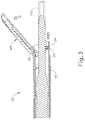
- end effector (40) includes an ultrasonic blade (100) and a pivoting clamp arm (44).
- Clamp arm (44) is pivotably coupled with a distal end of outer sheath (32) of shaft assembly (30) above ultrasonic blade (100) via a pin (45).
- a distal end of inner tube (34) is rotatably coupled with a proximal end of clamp arm (44) below ultrasonic blade (100) via a pin (35) such that longitudinal translation of inner tube (34) causes rotation of clamp arm (44) about pin (45) toward and away from ultrasonic blade (100) to thereby clamp tissue between clamp arm (44) and ultrasonic blade (100) to cut and/or seal the tissue.
- proximal longitudinal translation of inner tube (34) relative to outer sheath (32) and handle assembly (20) causes clamp arm (44) to move toward ultrasonic blade (100); and distal longitudinal translation of inner tube (34) relative to outer sheath (32) and handle assembly (20) causes clamp arm (44) to move away from ultrasonic blade (100).
- pivoting of trigger (28) toward pistol grip (24) will cause clamp arm (44) to move toward ultrasonic blade (100); and that pivoting of trigger (28) away from pistol grip (24) will cause clamp arm (44) to move away from ultrasonic blade (100).
- one or more resilient members are used to bias clamp arm (44) and/or trigger (28) to the open position shown in FIG. 4 .
- An ultrasonic transducer assembly (12) extends proximally from body (22) of handle assembly (20). While transducer assembly (12) is shown in FIG. 1 , transducer assembly (12) is omitted from FIG. 4 .
- Transducer assembly (12) is coupled with a generator (16) via a cable (14).
- Transducer assembly (12) receives electrical power from generator (16) and converts that power into ultrasonic vibrations through piezoelectric principles.
- Generator (16) may include a power source and control module that is configured to provide a power profile to transducer assembly (12) that is particularly suited for the generation of ultrasonic vibrations through transducer assembly (12).
- generator (16) may comprise a GEN 300 sold by Ethicon Endo-Surgery, Inc.
- generator (16) may be constructed in accordance with at least some of the teachings of U.S. Pub. No. 2011/0087212 , entitled “Surgical Generator for Ultrasonic and Electrosurgical Devices,” published April 14, 2011. It should also be understood that at least some of the functionality of generator (16) may be integrated into handle assembly (20), and that handle assembly (20) may even include a battery or other on-board power source such that cable (14) is omitted. Still other suitable forms that generator (16) may take, as well as various features and operabilities that generator (16) may provide, will be apparent to those of ordinary skill in the art in view of the teachings herein.
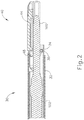
- Ultrasonic vibrations that are generated by transducer assembly (12) are communicated along an acoustic waveguide (102), which extends through shaft assembly (30) to reach ultrasonic blade (100).
- the proximal end of waveguide (102) includes a threaded recess (103), which is removably coupled with a threaded stud (not shown) that extends distally from transducer assembly (12). This provides a secure mechanical and acoustic coupling between transducer assembly (12) and waveguide (102).
- Waveguide (102) is secured within shaft assembly (30) via a pin (33), which passes through waveguide (102) and shaft assembly (30).
- Pin (33) is located at a position along the length of waveguide (102) corresponding to a node associated with resonant ultrasonic vibrations communicated through waveguide (102).
- waveguide (102) may be configured to amplify mechanical vibrations transmitted through waveguide (102).
- waveguide (102) may include features operable to control the gain of the longitudinal vibrations along waveguide (102) and/or features to tune waveguide (102) to the resonant frequency of the system.
- the distal end of ultrasonic blade (100) is located at a position corresponding to an anti-node associated with resonant ultrasonic vibrations communicated through waveguide (102), in order to tune the acoustic assembly to a preferred resonant frequency f o when the acoustic assembly is not loaded by tissue.
- the distal end of ultrasonic blade (100) is configured to move longitudinally in the range of, for example, approximately 10 to 500 microns peak-to-peak, and in some instances in the range of about 20 to about 200 microns at a predetermined vibratory frequency f o of, for example, 55.5 kHz.
- transducer assembly (12) of the present example When transducer assembly (12) of the present example is activated, these mechanical oscillations are transmitted through the waveguide (102) to reach ultrasonic blade (100), thereby providing oscillation of ultrasonic blade (100) at the resonant ultrasonic frequency.
- the ultrasonic oscillation of ultrasonic blade (100) may simultaneously sever the tissue and denature the proteins in adjacent tissue cells, thereby providing a coagulative effect with relatively little thermal spread.
- an electrical current may also be provided through ultrasonic blade (100) and clamp arm (44) to also seal the tissue.
- buttons (26) may be activate buttons (26) to selectively activate transducer assembly (12) to activate ultrasonic blade (100).
- two buttons (26) are provided - one for activating ultrasonic blade (100) at a low power and another for activating ultrasonic blade (100) at a high power.
- a foot pedal may be provided to selectively activate transducer assembly (12).
- Buttons (26) of the present example are positioned such that an operator may readily fully operate instrument (10) with a single hand. For instance, the operator may position their thumb about pistol grip (24), position their middle, ring, and/or little finger about trigger (28), and manipulate buttons (26) using their index finger.
- any other suitable techniques may be used to grip and operate instrument (10); and buttons (26) may be located at any other suitable positions.
- instrument (10) may be configured in numerous other ways as will be apparent to those of ordinary skill in the art in view of the teachings herein.
- at least part of instrument (10) may be constructed and/or operable in accordance with at least some of the teachings of any of the following: U.S. Pat. No. 5,322,055 ; U.S. Pat. No. 5,873,873 ; U.S. Pat. No. 5,980,510 ; U.S. Pat. No. 6,325,811 ; U.S. Pat. No. 6,783,524 ; U.S. Pub. No. 2006/0079874 ; U.S. Pub. No.
- waveguide (102) is mechanically and acoustically coupled with transducer assembly (12) by a threaded stud of transducer assembly (12), which is threaded into a threaded recess (103) formed in the proximal end of waveguide (102).
- Instrument (10) may be provided to the operator in a state where shaft assembly (30) is decoupled from handle assembly (20) and transducer assembly (12).
- the operator grasps shaft assembly (30) with one hand and transducer assembly (12) with the other hand; then rotates shaft assembly (30) relative to transducer assembly (12) in order to threadably couple the threaded stud of transducer assembly (12) in threaded recess (103) of waveguide (102).
- a torque wrench may be used to adjust this coupling with an appropriate amount of torque.
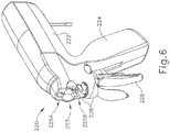
- FIGS. 5-14D show an exemplary instrument (210) having a shaft assembly (230) that is configured to selectively couple with a handle assembly (220) and transducer assembly (12) through activation of a motor (250).
- Instrument (210) of the present example is configured to operate substantially similar to instrument (10) discussed above except for the differences discussed below.
- instrument (210) is configured to clamp tissue between a pivoting clamp arm (244) and an ultrasonic blade (242) of an end effector (240); and cut/seal the tissue by ultrasonically activating blade (242).
- Instrument (210) of the present example comprises a handle assembly (220), a shaft assembly (230), and an end effector (240).
- Shaft assembly (230) comprises an outer sheath (232), an inner tube (not shown) slidably disposed within outer sheath (232), and a waveguide (not shown) disposed within the inner tube.
- longitudinal translation of the inner tube of the present example causes actuation of clamp arm (244) of end effector (240).
- Handle assembly (220) comprises a body (222) including a pistol grip (224) and a pair of buttons (226).
- Handle assembly (220) also includes a trigger (228) that is pivotable toward and away from pistol grip (224).
- Trigger (228) is pivotably coupled to handle assembly (220). Pivotal movement of trigger (228) causes longitudinal translation of the inner tube to thereby cause pivotal movement of clamp arm (244) toward and away from ultrasonic blade (242).
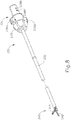
- handle assembly (220) is configured to receive and selectively secure shaft assembly (230) therein.
- a distal portion of body (222) of handle assembly (220) defines a keyed bore (223) defining a pair of longitudinal slots (225A, 225B).
- Keyed bore (223) of body (222) provides access to the interior of handle assembly (220) and is configured to receive a proximal engagement housing (231) of shaft assembly (230).
- proximal engagement housing (231) of shaft assembly (230) defines a pair of longitudinal projections (236A, 236B).
- Longitudinal slots (225A, 225B) are configured to receive longitudinal projections (236A, 236B) of proximal engagement housing (231) as shaft assembly (230) is inserted into keyed bore (223) of body (222) to thereby prevent rotation of shaft assembly (230) as shaft assemble (230) is secured to handle assembly (220); and to ensure proper alignment of features at proximal engagement housing (231) of shaft assembly (230) with corresponding components at the distal portion of handle assembly (220).
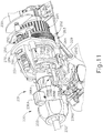
- handle assembly (220) comprises a plurality of internal components configured to selectively secure shaft assembly (230) within handle assembly (220).
- handle assembly (220) comprises a support member (270) that is configured to provide structural support for the internal components of handle assembly (220).
- Support member (270) defines an opening (272).
- a rotatable housing (264) is rotatably disposed within opening (272) of support member (270) and is secured therein such that housing (264) is operable to rotate relative to support member (270).
- a pair of bushings (269) provide further structural support to housing (264) in body (222), while allowing housing (264) to rotate freely within body (222).
- Transducer assembly (12) is disposed within housing (264) and is secured therein such that rotation of housing (264) relative to body (222) causes concurrent rotation of transducer assembly (12) relative to body (222).
- the proximal portion of housing (264) defines an angularly spaced array of longitudinally extending spline recesses (265).
- a ring gear (262) is coaxially disposed about the proximal portion of housing (264). Ring gear (262) includes an angular array of inner splines (not shown) that are disposed in spline recesses (265) of housing (264). It should therefore be understood that ring gear (262) and housing (264) rotate concomitantly; yet housing (264) may translate longitudinally relative to ring gear (262).
- the exterior of ring gear (262) includes a plurality of outwardly projecting teeth (263).
- Handle assembly (220) further comprises a motor (250), which is fixedly secured within the interior of body (222).
- Motor (250) is operable to rotate a drive axle (252), which rotatably supported by support member (270).
- Axle (252) comprises a threaded region (254) and plurality of teeth (256) extending from an exterior of axle (252). Teeth (256) of axle (252) engage teeth (263) of ring gear (262) such that rotation of axle (252) causes rotation ring gear (262).
- rotation of ring gear (262) provides rotation of housing (264) due to splined engagement with spline recesses (265) of housing (264).
- motor (250) is operable to rotate transducer assembly (12) via axle (252), ring gear (262), and housing (264). As described in greater detail below, this motor activated rotation of transducer assembly (12) will thread the threaded stud (13) (see FIGS. 7 and 12 ) of transducer assembly (12) into a threaded bore defined in the proximal end of the waveguide (e.g., similar to threaded bore (103) of waveguide (102)), such that transducer assembly (12) may be mechanically and acoustically coupled with the waveguide.
- Support member (270) defines a plurality of openings (271A, 271B, 271C, 271D).
- a plurality of guide posts (274A, 274B, 274C, 274D) are disposed within openings (271A, 271B, 271C, 271D) and secured therein.
- Handle assembly (220) further comprises a longitudinally translatable housing (280). Housing (280) defines a plurality of through bores (281A, 281B, 281C, 281D).
- Guide posts (274A, 274B, 274C, 274D) are slidably disposed in bores (281A, 281B, 281C, 281D) such that housing (280) is operable to translate between a proximal position and a distal position along guide posts (274A, 274B, 274C, 274D).
- housing (280) is positioned along guide posts (274A, 274B, 274C, 274D) distal to support member (270).
- a spring (282) is positioned between a distal face of support member (270) and a proximal face of housing (280) such that housing (280) is resiliently biased distally away from support member (270).
- Housing (280) defines a vertical slot (284).
- a threaded member (286) is positioned within vertical slot (284).
- An interior bore (291) of threaded member (286) defines an internal threading that is configured to threadably engage threaded region (254) of axle (252).
- rotation of axle (252) causes longitudinal translation of threaded member (286) and housing (280) along axle (252).
- axle (252) rotates, axle (252) rotates transducer assembly (12) while simultaneously driving housing (280) proximally.
- housing (280) further comprises a pair of distally extending resilient members (288A, 288B), each comprising a respective inwardly extending tab (289A, 289B).
- proximal engagement housing (231) of shaft assembly (230) defines a plurality of outwardly extending tabs (238A, 238B, 238C, 238D).
- Tabs (238A, 238B, 238C, 238D) are configured to engage inwardly extending tabs (289A, 289B) as shaft assembly (230) is inserted into handle assembly (220) via keyed bore (223) of body (222).
- shaft assembly (230) is driven proximally as well due to engagement between inwardly extending tabs (289A, 289B) of resilient members (288A, 288B) and outwardly extending tabs (238A, 238B, 238C, 238D) of shaft assembly (230). It should be understood that this proximal movement will accommodate threading of stud (13) of transducer assembly (12) into the proximal end of the waveguide.
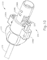
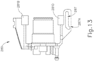
- handle assembly (220) comprises a locking member (266) that is slidably and rotatably coupled to housing (280) via a pin (267) passing through a slot (287) formed in a bottom of housing (280). Slot (287) is best seen in FIG. 13 . Pin (267) is best seen in FIGS. 14A-14D .
- a distal portion of locking member (266) comprises a pair of teeth (268) that are configured to engage a pair of teeth (235) extending from the proximal portion of shaft assembly (230) as best seen in FIG. 10 .
- Trigger (228) is coupled with locking member (266) via a linkage (229) such that rotation of trigger (228) causes longitudinal translation of locking member (266).
- a first end of linkage (229) is rotatably coupled with a proximal portion of trigger (228).
- a second end of linkage (229) is rotatably coupled with a proximal portion of locking member (266).
- a distal portion (287A) of slot (287) is angled such that as locking member (266) is driven longitudinally proximally via pivotal movement of trigger (228) toward pistol grip (224), the angled portion of slot (287) causes the proximal portion of locking member (266) to be driven upward via pin (267) to thereby engage teeth (235) of shaft assembly (230).
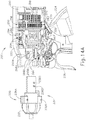
- FIGS. 14A-14D show the steps of securing shaft assembly (230) within handle assembly (220).
- Shaft assembly (230) is moved proximally from a position distal of handle assembly (220) ( FIG. 14A ) such that inwardly extending tabs (289A, 289B) of resilient members (288A, 288B) have engaged outwardly extending tabs (238A, 238B, 238C, 238D) of shaft assembly (230) as shown in FIG. 14B .
- a proximal end of the waveguide contacts threaded stud (13) of transducer assembly (12).
- housing (280) is in a distal position along guide posts (274A, 274B, 274C, 274D).
- Motor (250) is then activated.
- motor (250) may be automatically activated by a sensor that detects the positioning of shaft assembly (230) as shown in FIG. 14B .
- motor (250) may be manually activated by the operator depressing a button or other input feature.
- motor (250) may be activated by a combination of conditions including a sensor detecting the positioning of shaft assembly (230) as shown in FIG. 14B and an operator depressing a button, etc.
- Other suitable ways in which motor (250) may be activated will be apparent to those of ordinary skill in the art in view of the teachings herein.
- axle (252) is rotated such that ring gear (262), housing (264), and transducer assembly (12) also rotate relative to body (222).
- Shaft assembly (230) remains rotationally stationary relative to body (222) such that stud (12) of transducer assembly (12) is threaded onto the threaded bore defined in the proximal end of the waveguide.
- the splined engagement between ring gear (262) and housing (264) allows housing (264) and transducer assembly (12) to translate distally within body (222) as stud (13) threadably advances into the proximal end of the waveguide.
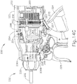
- a coil spring, leaf spring, or other resilient member provides a distal bias to housing (264), further promoting distal advancement of housing (264) and transducer assembly (12) as stud (13) threadably advances into the proximal end of the waveguide. Also as axle (252) rotates, threaded region (254) of axle (252) engages threaded interior bore of threaded member (286) such that rotation of axle (252) causes proximal longitudinal translation of threaded member (286) and housing (280) toward a proximal position as shown in FIG. 14C .
- housing (280) drives shaft assembly (230) proximally such that proximal engagement housing (231) of shaft assembly (230) is positioned within keyed bore (223) of handle assembly (220). Also in this proximal position, stud (13) of transducer assembly (12) has been completely threaded into the waveguide.
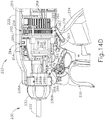
- FIG. 14D shows locking member (266) engaged with housing (280) via pivotal movement of trigger (228) toward pistol grip (224).
- a portion of shaft assembly (230) (e.g., one of longitudinal projections (236A, 236B), etc.) includes an RFID chip and/or other identifying feature that identifies the operating modality of shaft assembly (230).
- Handle assembly (220) may include a reader and a control logic that are operable to detect such an identifying feature and react accordingly.
- handle assembly (220) may be configured to operate with shaft assemblies (230) that include an ultrasonic blade (242) at end effector (240) and shaft assemblies that include RF electrosurgical features at the end effector.
- the reader may detect that a shaft assembly (230) that includes an ultrasonic blade (242) is being coupled with handle assembly (220).
- the control logic may activate motor (250) accordingly to couple transducer assembly (12) with the waveguide of shaft assembly (230).
- the reader may detect that a shaft assembly that includes RF electrosurgical features at the end effector is being coupled with handle assembly (220).
- the control logic may refrain from activating motor (250) accordingly.
- an identifier or other feature of shaft assembly (230) may nevertheless activate a complementary feature in handle assembly (220), which may in turn activate motor (250) in response to detection of shaft assembly (230) at the distal end of handle assembly (220).
- handle assembly (220) may include a user input feature that is operable to eject shaft assembly (230) from handle assembly (220). For instance, this user input feature may cause motor (250) to operate in reverse to decouple the waveguide from transducer assembly (12) and to decouple shaft assembly (250) from housing (280).
- handle assembly (220) may include one or more motion sensors (e.g., accelerometers, etc.) that may be used to manage energy conservation based on whether and/or how an operator is using instrument (210).
- handle assembly (220) may include one or more features configured to ensure that an appropriate amount of torque (e.g., between approximately 5 inch-pounds (0.565 joules) and approximately 10 inch-pounds (1.130 joules) etc.) is applied to the coupling of stud (13) with the waveguide.
- an encoder, one or more hall effect sensors, one or more reed switch.es, and/or various other kinds of components may be used to track the turns of stud (13); and a control logic may stop motor (250) when stud (13) as turned through an angular range associated with an appropriate torque value.
- a control module may track a back electromotive force (EMF) associated with motor (250); and stop motor (250) when the hack EMF has reached a value associated with an appropriate torque value.
- EMF back electromotive force
- a clutch feature such as a ratcheting assembly described below, a one-way bearing assembly, and/or some other feature may provide slipping of drive features when an appropriate torque value is achieved at the coupling of the threaded stud of the transducer and the waveguide. This slipping may cause a sudden drop in the back EMF associated with motor (250), a sudden increase in the rotation speed of a now “freewheeling" drive component, and/or some other detectable condition. This drop in the hack EMF, increase in rotation speed, or other change in condition may be detected by a control module to trigger deactivation of motor (250).
- shaft assembly (230) may be varied in numerous ways.
- shaft assembly (230) is operable to selectively transition between a first configuration where outer sheath (232), the inner tube, the waveguide, and end effector (240) arc rotatable relative to proximal engagement housing (231); and a second configuration where outer sheath (232), the inner tube, the waveguide, and end effector (240) are not rotatable relative to proximal engagement housing (231).
- a rotation knob (233) of shaft assembly (230) may be keyed to outer sheath (232) may be configured to translate between a proximal position and a distal position along outer sheath (232).
- proximal engagement housing (231) When rotation knob (233) is in the proximal position, features within proximal engagement housing (231) may lock the rotational position of outer sheath (232), the inner tube, the waveguide, and end effector (240) relative to proximal engagement housing (231). When rotation knob (233) is in the distal position, features within proximal engagement housing (231) may allow outer sheath (232), the inner tube, the waveguide, and end effector (240) to rotate relative to proximal engagement housing (231). Moreover, a resilient feature may bias rotation knob (233) to the proximal position, such that the operator must overcome this bias in order to move rotation knob (233) distally to provide rotation of shaft assembly (230).
- outer sheath (232), the inner tube, the waveguide, and end effector (240) are only rotatable relative to proximal engagement housing (231) after shaft assembly (230) has been coupled with handle assembly (220) as described above. This may also prevent the waveguide from rotating during the coupling operation as described above.
- shaft assembly (230) is operable to selectively transition between a first configuration where outer sheath (232), the inner tube, the waveguide, and end effector (240) are rotatable relative to proximal engagement housing (231); and a second configuration where outer sheath (232), the inner tube, the waveguide, and end effector (240) are not rotatable relative to proximal engagement housing (231); housing (280) may be operable to selectively transition shaft assembly (230) between the first configuration and the second configuration.
- housing (280) when housing (280) is in a distal position within body (222), housing (280) may place shaft assembly (230) in a configuration where outer sheath (232), the inner tube, the waveguide, and end effector (240) are not rotatable relative to proximal engagement housing (231). Conversely, when housing (280) is in a proximal position within body (222), housing (280) may place shaft assembly (230) in a configuration where outer sheath (232), the inner tube, the waveguide, and end effector (240) are rotatable relative to proximal engagement housing (231). It should be understood that threaded region (254) of axle (252) may drive housing (280) between the distal and proximal positions.
- motor (250) may be operable to transition shaft assembly (230) between rotationally locked and rotationally unlocked configurations, in coordination with the threaded coupling of transducer assembly (12) with the waveguide.
- the above noted components may provide shaft assembly (230) in a rotationally locked configuration while transducer assembly (12) is being threadably coupled with the waveguide; then provide shaft assembly (230) in a rotationally unlocked configuration once transducer assembly (12) has been suitably coupled with the waveguide.
- Other suitable features, components, and functionalities that may be incorporated into shaft assembly (230) will be apparent to those of ordinary skill in the art in view of the teachings herein.
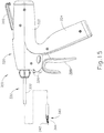
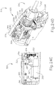
- FIGS. 15-24D show another exemplary instrument (310) having a shaft assembly (330) that is configured to selectively couple with a handle assembly (320) and transducer assembly (12) through activation of a motor (350).
- Instrument (310) of the present example is configured to operate substantially similar to instruments (10, 210) discussed above except for the differences discussed below.
- instrument (310) is configured to clamp tissue between a pivoting clamp arm (344) and an ultrasonic blade (342) of an end effector (340); and cut/seal the tissue by ultrasonically activating blade (342).
- Instrument (310) of the present example comprises handle assembly (320), a shaft assembly (330), and an end effector (340).
- Shaft assembly (330) comprises an outer sheath (332), an inner tube (not shown) slidably disposed within outer sheath (332), and a waveguide (not shown) disposed within the inner tube.
- longitudinal translation of the inner tube of the present example causes actuation of clamp arm (344) of end effector (340).
- Handle assembly (320) comprises a body (322) including a pistol grip (324) and a pair of buttons (326).
- Handle assembly (320) also includes a trigger (328) that is pivotable toward and away from pistol grip (324).
- Trigger (328) is pivotably coupled to handle assembly (320). Pivotal movement of trigger (328) causes longitudinal translation of the inner tube to thereby cause pivotal movement of clamp arm (344) toward and away from ultrasonic blade (342).
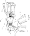
- handle assembly (320) is configured to receive and selectively secure handle assembly (330) therein.
- distal end of body (322) of handle assembly (320) defines a circular bore (325) that is configured to receive a proximal portion (331) of shaft assembly (330).
- a socket housing (346) is positioned within circular bore (325). Socket housing (346) is configured to insertingly receive proximal portion (331) of shaft assembly (330).
- FIG. 18-19 distal end of body (322) of handle assembly (320) defines a circular bore (325) that is configured to receive a proximal portion (331) of shaft assembly (330).
- a socket housing (346) is positioned within circular bore (325). Socket housing (346) is configured to insertingly receive proximal portion (331) of shaft assembly (330).
- proximal portion (331) of shaft assembly (330) comprises a plurality of longitudinal splines (336) extending from an exterior surface of shaft assembly (230) and arranged in an angular array.
- Splines (336) define a plurality of longitudinal slots (337) between consecutive splines (336).
- a locking member (380) is configured to move into and out of slots (337) to engage adjacent splines (336), to thereby prevent rotation of shaft assembly (330) relative to handle assembly (320) during assembly of instrument (310).
- a transducer assembly (not shown), which may be configured and operable like transducer assembly (12) described above, is secured within a transducer housing (312) in body (322) of handle assembly (320).
- Transducer housing (312) is configured to rotate within body (322) of handle assembly (320).
- the transducer is fixedly secured within transducer housing (312), such that the transducer rotates with transducer housing (312) relative to body (322) of handle assembly (320).
- a drive gear (314) is fixedly secured to the proximal end of transducer housing (312), such that drive gear (314) may be driven to rotate transducer housing (312) relative to body (322) of handle assembly (320).
- the waveguide of shaft assembly (330) may include a threaded bore that is configured to receive a complementary threaded stud of the transducer assembly, similar to the relationships described elsewhere herein, to mechanically and acoustically couple the transducer assembly with the waveguide upon sufficient rotation of the transducer assembly relative to shaft assembly (330).
- Handle assembly (320) comprises a plurality of internal components configured to selectively secure the transducer assembly of handle assembly (320) with the waveguide of shaft assembly (330).
- handle assembly (320) comprises a motor (350) that is operable to secure the transducer assembly of handle assembly (320) with the waveguide of shaft assembly (330) in response to pivoting of a lever arm (360) relative to handle assembly (320).
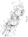
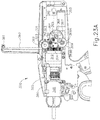
- Motor (350) is operable to rotate a drive gear (352), which is coaxially aligned with and secured to the integral drive shaft (351) of motor (350) as best seen in FIG. 21 .
- a drive gear (352) which is coaxially aligned with and secured to the integral drive shaft (351) of motor (350) as best seen in FIG. 21 .
- gears (352, 314) the teeth of drive gear (352) mesh with the teeth of gear (314), such that motor (350) is operable to drive rotation of transducer housing (312) relative to body (322) of handle assembly (320) through meshing engagement of gears (352, 314).
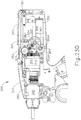
- lever arm (360) is rotatably coupled with a chassis (321) in body (322) via a pin (323) such that lever arm (360) is rotatable relative to body (322) between a plurality of rotational positions.
- Lever arm (360) is also coupled to a gear (362) via pin (323) such that pivoting of lever arm (360) about pin (323) causes rotation of gear (362).
- Gear (362) is rotatably supported by chassis (321) and meshes with another gear (363), which is also rotatably supported by chassis (321).
- Gear (363) meshes with another gear (364), which is also rotatably supported by chassis (321).
- Gear (364) meshes with another gear (365), which is also rotatably supported by chassis (321).
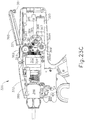
- Gear (365) is secured to an axle (366) with another gear (367), such that gears (365, 367) rotate together with axle (366) relative to chassis (321).
- a portion of gear (367) is omitted in FIG. 23B to better depict gear (365) and the meshing engagement between gears (364, 365).
- Gear (367) meshes with another gear (369), which is secured to an oblong pin (369A) of a rotary damper (369B).
- Rotary damper (369B) is fixedly secured to chassis (321).
- Rotary damper (369B) comprises a conventional rotary damper that is configured to slow the actuation of lever arm (360), reducing the angular velocity at which lever arm (360) pivots and providing some degree of tactile resistance to pivoting of lever arm (360).
- a conventional sensor is used to track pivotal movement of lever arm (360).
- a control module is in communication with this sensor and motor (350), and is thus configured to activate motor (350) based on the pivotal position of lever arm (380) relative to body (322).
- a sensor may comprise an encoder assembly with an encoder wheel coaxially positioned about pin (323) or about the shaft of any one of gears (362, 363, 364, 365, 367, 369).
- the sensor may include one or more hall effect sensors, one or more reed switches, and/or various other kinds of components.
- a control module may activate motor ⁇ 350) in response to one or more sensors detecting pivotal movement of lever arm (380) relative to body (322); and de-activate motor (350) upon lever arm (380) reaching a predetermined pivotal position relative to body (322).
- one or more features may be provided to ensure that an appropriate amount of torque (e.g., between approximately: 5 inch-pounds (0.565 joules) and approximately 10 inch-pounds (1.130 joules) etc.) is applied to the coupling of the ultrasonic transducer assembly with the acoustic waveguide,
- an encoder, one or more hall effect sensors, one or more reed switches, and/or various other kinds of components may be used to track the turns of the transducer assembly; and a control logic may stop motor (350) when the transducer assembly as turned through an angular range associated with an appropriate torque value.
- a control module may further track a back electromotive force (EMF) associated with motor (350); and deactivate motor (350) in response to the back EMF reaching a value associated with an appropriate torque value at the coupling of the threaded stud of the transducer and the waveguide.
- EMF back electromotive force
- a clutch feature such as a ratcheting assembly described below, a one-way bearing assembly, and/or some other feature may provide slipping of drive features when an appropriate torque value is achieved at the coupling of the threaded stud of the transducer and the waveguide.
- This slipping may cause a sudden drop in the back EMF associated with motor (350), a sudden increase in the rotation speed of a now freewheeling" drive component, and/or some other detectable condition.
- This drop in the back EMF, increase in rotation speed, or other change in condition may be detected by a control module to trigger deactivation of motor (350).
- Other suitable ways in which one or more sensors may be used, as well as other suitable ways in which motor (350) may be controlled e.g., to deactivate motor (350) upon a certain torque value being achieved, etc.
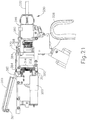
- lever arm (360) is also coupled with a pulley member (381) via pin (323) such that rotation of lever arm (360) causes rotation of pulley member (381).
- Pulley member (381) defines an arcuate channel (383).
- a cable (384) is disposed within channel (383) of pulley member (381) such that rotation of pulley member (381) causes longitudinal translation of cable (384).
- longitudinal translation of cable (384) is selectively locks and unlocks rotation of shaft assembly (330) relative to handle assembly (320) via locking member (380).
- a distal portion of cable (384) slidably passes through a pair of through bores (368A, 368B) formed in a housing (368), such that cable (384) redirects by 180° through housing (368).
- a distal end of cable (384) is coupled to a longitudinally translatable member (370), which is proximal to housing (368), such that proximal longitudinal translation of cable (384) causes distal longitudinal translation of member (370).
- member (370) may be proximally biased such that cable (384) is distally biased as well.
- cable (384) is coupled with a tensioning spring (365) to thereby take up slack within cable (384).
- tensioning spring (365) pulls cable (384) laterally to resiliently shorten the effective length of cable (384) while cable (384) is laterally deformed by tensioning spring (365).
- Member (370) is coupled to a proximal end of locking member (380) such that longitudinal translation of member (370) causes concurrent longitudinal translation of locking member (380).
- a distal end of locking member (380) comprises a downwardly extending tab (382).
- the distal end of locking member (380), including tab (382), is slidably disposed within a longitudinal slot (348) of a socket housing (346) positioned within a distal portion of handle assembly (320). (Housing (346) has been omitted from FIGS. 17-19 , 24B , and 24D for the sake of clarity.)
- Tab (382) is configured to fit within slots (337) of shaft assembly (330) to thereby selectively lock and unlock shaft assembly (330).
- tab (382) is positioned within slots (337) of shaft assembly (330) when member (380) is in a proximal position, thereby preventing shaft assembly (330) from rotating relative to handle assembly (320).
- tab (382) is spaced distally of slots (337) and splines (336), thereby permitting shaft assembly (330) to rotate relative to handle assembly (320).
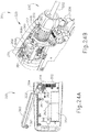
- FIGS. 22A-24D show exemplary steps of securing shaft assembly (330) within handle assembly (320).
- a proximal portion of shaft assembly (320) is first inserted proximally into socket housing (346).
- lever arm (360) is at a first pivotal position relative to body (322) of handle assembly (320) at this stage.
- locking member (380) is proximally positioned such that tab (382) is disposed in a slot (337) between adjacent splines (336), preventing shaft assembly (330) from rotating relative to handle assembly (320).
- the operator then begins to pivot lever arm (360) toward body (322), from the position shown in FIG.
- lever arm (360) activates motor (350) to rotate gear (352) which in turn rotates the transducer assembly via gear (314) and transducer housing (312).
- an encoder and/or other kind of sensor may detect pivotal movement of lever arm (360) from the position from the position shown in FIG. 23A to the position shown in FIG. 23B , with motor (350) being responsive to a signal from the encoder and/or other kind of sensor.
- gear (362) is substituted with a sector gear with teeth arranged such that gear (362) does not engage gear (363) during the transition from the configuration shown in FIG. 23A to the configuration shown in FIG. 23B .
- lever arm (360) After reaching the stage shown in FIG. 23B , the operator continues to pivot lever arm (360) toward body (322) to the position shown in FIG. 23C .
- lever arm (360) drives gears (362, 363, 364, 365, 367, 369) such that rotary damper (369B) dampens the pivotal movement of lever arm (360) relative to body (322).
- Motor (350) continues to rotate transducer housing (312), thereby further threading the stud of the transducer into the threaded recess of the waveguide until a suitable level of torque is achieved at the coupling of the threaded stud with the waveguide.
- motor (350) upon reaching the position shown in FIG. 23C , motor (350) has provided a predetermined amount of torque to suitably couple the transducer assembly with the waveguide mechanically and acoustically. Motor (350) is then deactivated, even as lever arm (360) continues to pivot toward body (322).
- cable (384) retracts proximally during the stages shown in FIGS. 22A-22C , and up until lever arm (360) reaches the position shown in FIGS. 22D and 24C , yet cable (384) does not advance locking member (380) during this proximal movement of cable (384). Instead, cable (384) extends tensioning spring (365) during this proximal movement of cable (384). By the time lever arm (360) reaches the position shown in FIGS. 22D and 24C , tensioning spring (365) is fully extended and is no longer laterally deflecting cable (384), such that further proximal movement of cable (384) will provide the distal advancement of locking member (380).
- instrument (310) may be ready for operation.
- the proximal end of lever arm (360) includes a resiliently biased ball detent feature (361) that is configured to engage a complementary recess formed in body (322) of handle assembly (320), to thereby assist in maintaining lever arm (360) in the position shown in FIGS. 22D and 24C .
- ball detent feature (361) may be used in addition to or in lieu of ball detent feature (361).
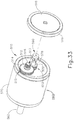
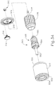
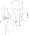
- FIGS. 54-56C show exemplary alternative features that may be incorporated into instrument (310) to couple a transducer with an acoustic waveguide.
- FIGS. 54-55 show a transducer housing (812), which is rotatably supported within a body (822) of a handle assembly.
- An ultrasonic transducer assembly is secured within transducer housing (812), such that the ultrasonic transducer assembly rotates with transducer housing (812) relative to body (822).
- a clutch ring (830) is fixedly secured to the exterior of body (822) and is coaxially disposed in relation to the ultrasonic transducer assembly.
- Clutch ring (830) includes a set of obliquely angled, distally facing teeth (830).
- Teeth (830) are engaged with obliquely angled, proximally facing teeth (842) of a clutch drive gear (840), which is also coaxially aligned with the ultrasonic transducer assembly.
- Clutch drive gear (840) is resiliently biased in the proximal direction, such that teeth (842) are biased into engagement with teeth (832).
- clutch drive gear (840) is operable to drive clutch ring (830) and transducer housing (812) in a first rotational direction until a certain torque threshold is reached, at which point teeth (842) begin to slip against teeth (832) such that clutch drive gear (840) no longer drives clutch ring (830) and transducer housing (812) in the first rotational direction after the certain torque threshold is reached.
- clutch drive gear (840) is operable to drive clutch ring (830) and transducer housing (812) in a second rotational direction regardless of the torque.
- Clutch drive gear (840) includes an angularly spaced array of outwardly extending teeth (843). Teeth (843) are configured to mesh with a gear (not shown) of a drive shaft (not shown) of a motor (not shown). The motor may thus be operable to drive rotation of clutch drive gear (840), thereby driving rotation of clutch ring (830) and transducer housing (812) within body (822). By way of example only, teeth (843) may mesh with a gear like drive gear (352) described above, which is secured to drive shaft (351) of motor (350). Other suitable arrangements will be apparent to those of ordinary skill in the art in view of the teachings herein.
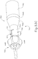
- a lever arm (860) is pivotally coupled with body (822).
- Lever arm (860) includes an integral sector gear (832) that rotates relative to body (822) as lever arm (860) pivots relative to body (822).
- Sector gear (832) includes a set of teeth (864) extending along only a portion of an angular range of the circumferential perimeter of sector gear (832). As will be described in greater detail below, these teeth (864) are positioned to mesh with complementary teeth of a gear (856) as lever arm (860) is pivoted through a certain range of motion relative to body (822).
- Gear (856) is unitarily coupled with another gear (852) along a pin (854), which is rotatably supported in body (822).
- Gear (852) meshes with another gear (848), which is unitarily coupled with a bevel gear (846) along a pin (850).
- Pin (850) is also rotatably supported in body (822).
- bevel gear (846) is engaged with another bevel gear (844), which is integrally disposed on the distal face of clutch drive gear (840).
- lever arm (860) is pivoted relative to body (822) through the range of motion where teeth (864) engage gear (856), the drivetrain formed by gears (862, 856, 852, 848, 846, 844) will rotate clutch drive gear (840) in body (822), thereby rotating clutch ring (830) and transducer housing (812) within body (822).
- a locking member (880) is slidably disposed in body (822), such that locking member (880) is configured to translate longitudinally within body (822).
- the proximal end of locking member (880) includes a downwardly extending integral cam feature (882).
- the distal end of locking member is configured to selectively engage features of a shaft assembly, to thereby selectively lock the rotational position of the shaft assembly relative to body (822).
- the distal end of locking member may include a feature similar to tab (382) as described above, which may be configured to engage splines of a shaft assembly similar to splines (336) as also described above. As best seen in FIGS.
- lever arm (860) includes an integral cam feature (866) that is configured to rotate about the same axis as lever arm (860) and sector gear (862) as lever arm (860) is pivoted relative to body (822).
- cam feature (866) of lever arm (860) is configured to engage cam feature (882) of locking member (880), thereby driving locking member (880) distally relative to body (822), as lever arm (860) is pivoted through a certain range of motion relative to body (822).
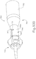
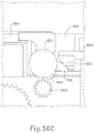
- FIGS. 56A-56B depict exemplary stages of operation.
- FIG. 56A depicts lever arm (860) in an initial pivotal position.
- the proximal end of a shaft assembly may be inserted into the distal end of body (822).
- Locking member (880) is in a proximal position, where the distal end of locking member (880) prevents rotation of the shaft assembly relative to body (822).
- locking member (880) may be resiliently biased to the proximal position by a coil spring, leaf spring, and/or some other resilient feature. The operator then pivots lever arm (860) from the position shown in FIG. 56A toward the position shown in FIG. 56B .
- a sensor senses the pivotal movement of lever arm (860) and activates the motor to rotate clutch drive gear (840) in body (822), thereby rotating clutch ring (830) and transducer housing (812) within body (822).
- This provides an initial threading of the threaded stud of the ultrasonic transducer into the proximal threaded recess of an acoustic waveguide as described elsewhere herein.
- sector gear (862) does not engage gear (856).
- Clutch ring (830) and transducer housing (812) are thus driven solely by the motor during the initial stages of the transition from the configuration shown in FIG. 56A to the configuration shown in FIG. 56B .
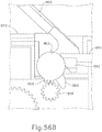
- lever arm (860) may continue to pivot lever arm (860) relative to body (822), to the position shown in FIG. 56C .
- cam feature (866) of lever arm (860) has engaged cam feature (882) of locking member (880), driving locking member (880) distally relative to body (822).
- This distal movement of locking member (880) disengages the distal end of locking member (880) from the shaft assembly, thereby enabling the shaft assembly to rotate relative to body (822).
- teeth (864) of sector gear (862) have cleared gear (856).
- the shaft assembly and transducer housing (812) may be free to rotate within body (822).
- Gears (856, 852, 848, 846, 844) may simply rotate freely within body (822).
- ratcheting clutch provided by teeth (832, 842) is replaced with an assembly formed by a one-way bearing and a smooth clutch plate.
- instrument (310) will be apparent to those of ordinary skill in the art in view of the teachings herein.
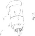
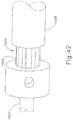
- FIGS. 25-27 show an exemplary assembly (420) that integrates a motor (450) and an ultrasonic transducer (460) in a coaxial relationship. Assembly (420) may be readily incorporated into instrument (10), to provide a motorized coupling between a transducer and a waveguide.
- Motor (450) of the present example comprises a stator (452) and a rotor (456).
- Stator (452) includes a flange (454) that defines diametrically opposing gaps (455) (only one gap (455) is shown in FIG. 26 ).
- Rotor (456) is coaxially and rotatably disposed within stator (452).
- motor (450) is a brushless motor.
- stator (452) may include windings that are selectively commutated while rotor (456) includes an angularly spaced array of permanent magnets, such that electromagnetic forces urge rotor (456) to rotate within stator (452) as the windings of stator (452) are selectively commutated.
- Other suitable components, features, and configurations that may be provided for stator (452) and rotor (456) will be apparent to those of ordinary skill in the art in view of the teachings herein.
- Ultrasonic transducer (460) is secured within rotor (456). As shown in FIG. 26 , ultrasonic transducer (460) of the present example comprises a horn (462), a mounting flange (464), a body (466), a stack of piezoelectric discs (468), and a bolt (469) that longitudinally compresses discs (468) against body (466). The compressed discs (468) are operable to convert electrical power into ultrasonic vibrations, which are communicated through body (466) to horn (462).
- Horn (462) may include a threaded stud or other coupling feature to mechanically and acoustically couple transducer (460) with a waveguide as described above.
- Flange (464) is located at a position corresponding to a node associated with ultrasonic vibrations generated by transducer (460).
- Housing (470) comprises a distal portion (472), a proximal portion (474), and an intermediate portion (476) which together define canister-like shroud.
- a proximal face of distal portion (472) includes a proximally extending tab (473).
- a distal face of intermediate portion (476) includes a distally extending tab (475).
- Tabs (473, 475) engage respective gaps (455) in flange (454) of stator (452), such that housing (470) and stator (452) are both rotationally secured relative to each other.
- housing (470) may be rotationally secured within the body of a handle assembly or other kind of body.
- Transducer (460) is secured to rotor (456) via flange (464).
- the distal face of rotor (456) includes an angular array of distally facing projections (458) that are configured to fit in complementary recesses (465) that are formed in the proximal face of flange (464).
- projections (458) disposed in recesses (465) transducer (460) and rotor (456) rotate together.
- Rotor (456) is further secured to a bushing (480), which provides a rotatable support between rotor (456) and stator (452).
- bushing (480) is positioned in distal portion (472) of housing (470) and thereby provides structural support to rotor (456) and transducer (460) while also permitting rotor (456) and transducer (460) to rotate within distal portion (472) of housing (470).
- An intermediate mounting feature (482) is disposed about rotor (456) and within intermediate portion (476) of housing. Intermediate mounting feature (482) provides support to rotor (456) and transducer (460) while also permitting rotor (456) and transducer to rotate within intermediate portion (476) of housing (470).
- a proximal mounting feature (484) is disposed about rotor (456) and within proximal portion (474) of housing. Intermediate mounting feature (482) provides support to rotor (456) and transducer (460) while also permitting rotor (456) and transducer to rotate within proximal portion (474) of housing (470).
- motor (450) may be activated to rotate transducer (460) relative to the body of a handle assembly or other kind of body. Motor (450) may thus be activated to rotatably drive a threaded stud extending distally from horn (462) into a threaded recess of a waveguide. Motor (450) may also be activated in reverse to decouple the waveguide from horn (462).
- assembly (420) may be integrated into instrument (10) and variations thereof will be apparent to those of ordinary skill in the art in view of the teachings herein.
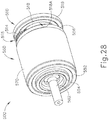
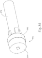
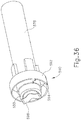
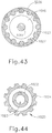
- FIGS. 28-37 show an exemplary assembly (500) that integrates a motor (550) with an ultrasonic transducer (560) and a set of gears (510). Assembly (500) may be readily incorporated into instrument (10), to provide a motorized coupling between a transducer and a waveguide.
- Motor (550) of the present example comprises a stator (570) and a rotor (576).
- Rotor (576) is coaxially and rotatably disposed within stator (570).
- motor (550) is a brushless motor.
- stator (570) may include windings that are selectively commutated while rotor (576) includes an angularly spaced array of permanent magnets, such that electromagnetic forces urge rotor (576) to rotate within stator (570) as the windings of stator (570) are selectively commutated.
- Other suitable components, features, and configurations that may be provided for stator (570) and rotor (576) will be apparent to those of ordinary skill in the art in view of the teachings herein.
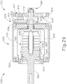
- Ultrasonic transducer (560) is secured within rotor (576). As shown in FIGS. 29 and 34 , ultrasonic transducer (560) of the present example comprises a horn (562), a mounting flange (564), a stack of piezoelectric discs (568), and a bolt (569) that longitudinally compresses discs (568). The compressed discs (568) are operable to convert electrical power into ultrasonic vibrations, which are communicated through horn (562).
- Horn (562) may include a threaded stud or other coupling feature to mechanically and acoustically couple transducer (560) with a waveguide as described above.
- Flange (564) is located at a position corresponding to a node associated with ultrasonic vibrations generated by transducer (560).
- Transducer (560) is secured to an interior portion of rotor (576) via flange (564), such that transducer (560) and rotor (576) rotate together.
- Rotor (576) is rotatably supported within stator (570) by a bushing (558), as best seen in FIG. 29 .
- Rotor (576) is also rotatably supported within the body of a handle assembly or some other instrument body by a distal bushing (554).
- Stator (570) is rotatably supported within the body of a handle assembly or some other instrument body by a pair of bushings (552, 556).
- stator (570) and rotor (576) may both rotate within the body of a handle assembly or some other instrument body.
- rotor (576) includes a stem (578) that extends proximally from rotor (576) through stator (570).
- Stem (578) provides a passageway for wires (not shown) that are electrically coupled with piezoelectric discs (568) of transducer (560), such that stem (578) serves as a pathway for electrical power delivery to piezoelectric discs (568) as will be described in greater detail below.
- horn (562) protrudes distally from stator (570), enabling horn (562) to be coupled with a waveguide as described herein.
- stator (570) includes an integral gear (572).
- Stem (578) passes through a bore formed through the axis of gear (572).
- Gear (572) has external teeth (573) that mesh with external teeth (515) of another gear (515).
- Gear (515) is secured to an axle (512) with another gear (516).
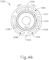
- Gear (516) has external teeth (517) that mesh with internal teeth (518A) of a ring gear (518).
- Ring gear (518) is rotatably supported by a bushing (519), which may be secured to the body of a handle assembly or some other instrument body. Ring gear (518) is fixedly secured to stem (578).
- ring gear (518) rotates unitarily with rotor (576) due to the coupling via stem (578).
- Rotation of ring gear (518) in a first direction causes rotation of gear (516) in the first direction, due to meshing of teeth (518A, 517).
- Rotation of gear (516) in the first direction causes rotation of gear (514) in the first direction, due to gears (514, 516) being secured to the same axle (512).
- Rotation of gear (514) in the first direction causes rotation of gear (572) in a second direction, due to meshing of teeth (515, 573).
- gear assembly (510) may compound the relative rotation between stator (570) and rotor (576). In some versions, gear assembly (510) provides a gear ratio of 13:1.
- a slip ring assembly (590) is positioned at the proximal end of stem (578) to provide electrical continuity between fixed wires and the wires passing through the interior of stem (578) to power transducer (560) while allowing stem (578) and transducer (560) to rotate relative to the fixed wires.
- Slip ring assembly (590) comprises a cap (591) and a first ring (592), which are electrically isolated from each other.
- Cap (591) provides a path for coupling a first fixed wire associated with a first electrical polarity; while ring (592) is coupled with a second fixed wire associated with a second electrical polarity.
- Cap (591) is engaged with a conductive leaf spring (598), which resiliently bears against a conductive plate (599) located at the proximal end of stem (578).
- Plate (599) is coupled with one or more wires in stem (578) associated with the first electrical polarity. It should be understood that leaf spring (598) and plate (599) together provide a path for electrical continuity between the first fixed wire and the one or more wires in stem (578) that are associated with the first electrical polarity; and that leaf spring (598) and plate (599) together maintain this electrical continuity while stem (578) rotates relative to the first fixed wire.
- a conductive projection (593) projects inwardly from ring (592) into engagement with another ring (594).
- Ring (594) is fixedly secured to the exterior of stem (578) and is electrically coupled with one or more wires in stem (578) that are associated with the second electrical polarity.
- Ring (592) resiliently biases projection (593) into engagement with ring (594), such that projection (593) slides against ring (594) while maintaining contact with ring (594).
- rings (592, 594) and projection (593) together provide a path for electrical continuity between the second fixed wire and the one or more wires in stem (578) that are associated with the second electrical polarity; and that rings (592, 594) and projection (593) together maintain this electrical continuity while stem (578) rotates relative to the second fixed wire.
- motor (550) may be activated to rotate transducer (560) relative to the body of a handle assembly or other kind of body. Motor (550) may thus be activated to rotatably drive a threaded stud extending distally from horn (562) into a threaded recess of a waveguide. Motor (550) may also be activated in reverse to decouple the waveguide from horn (562).
- assembly (500) may be integrated into instrument (10) and variations thereof will be apparent to those of ordinary skill in the art in view of the teachings herein.
- shaft assemblies (30) may be readily coupled with and decoupled from transducer assembly (12) and handle assembly (20) with relative ease.
- such coupling and decoupling of shaft assembly (30) may include coupling waveguide (102) with transducer assembly (12) and coupling inner tube (34) with coupling assembly (35) of yoke (25). It may be desirable to provide such coupling of waveguide (102) and such coupling of inner tube (34) simultaneously. In particular, it may be desirable to provide coupling of waveguide (102) and coupling of inner tube (34) simultaneously through set of coaxially arranged and radially spaced apart threaded features.
- FIGS. 38-49C show examples of various features that may provide such simultaneous coupling of waveguide (102) and coupling of inner tube (34) in a single rotational motion.
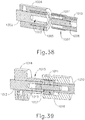
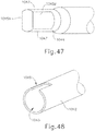
- FIG. 38 shows an exemplary waveguide (1002) coaxially disposed within an inner tube (1004).
- FIG. 38 also shows an exemplary horn (1010) coaxially disposed within a tube driver (1006).
- waveguide (1002) may be used in place of waveguide (102)
- inner tube (1004) may be used in place of inner tube (34)
- horn (1010) may be a feature of transducer assembly (12)
- tube driver (1006) may be a feature of coupling assembly (35) of yoke (25).
- the proximal end of waveguide (1002) includes a threaded bore (1003).
- the proximal end of tube (1004) also includes a threaded bore (1005).
- a stud (1011) with external threading extends distally from horn (1010).
- Threaded bore (1003) is configured to receive stud (1011) through a threaded engagement.
- Tube driver (1006) includes external threading (1007).
- Threaded bore (1005) is configured to receive external threading (1007) through a threaded engagement.
- waveguide (1002) may be coupled with horn (1010) simultaneously as inner tube (1004) is coupled with tube driver (1006) through a single rotational motion.
- ultrasonic vibrations generated by transducer assembly (12) may be communicated to waveguide (1002) via horn (1010).
- pivotal movement of trigger (28) may provide longitudinal translation of inner tube (1004) via tube driver (1006).
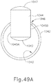
- FIG. 39 shows an exemplary waveguide (1012) coaxially disposed within an inner tube (1014).
- FIG. 39 also shows an exemplary horn (1010) coaxially disposed within a tube driver (1016).
- waveguide (1012) may be used in place of waveguide (102)
- inner tube (1014) may be used in place of inner tube (34)
- horn (1010) may be a feature of transducer assembly (12)
- tube driver (1016) may be a feature of coupling assembly (35) of yoke (25).
- the proximal end of waveguide (1012) includes a threaded bore (1013).
- the proximal end of tube (1014) includes a coupling sleeve (1015).
- a stud (1011) with external threading extends distally from horn (1010).
- Threaded bore (1013) is configured to receive stud (1011) through a threaded engagement.
- Tube driver (1016) includes internal threading (1017).
- Internal threading (1017) is configured to act as a self-tapping nut over sleeve (1015), such that threading (1017) may provide threaded engagement over sleeve (1015).
- sleeve (1015) includes pre-formed external threading that complements threading (1017). It should therefore be understood that waveguide (1012) may be coupled with horn (1010) simultaneously as inner tube (1014) is coupled with tube driver (1016) through a single rotational motion.
- waveguide (1012) is coupled with horn (1010)
- ultrasonic vibrations generated by transducer assembly (12) may be communicated to waveguide (1012) via horn (1010).
- pivotal movement of trigger (28) may provide longitudinal translation of inner tube (1014) via tube driver (1016).
- FIG. 40 shows an exemplary waveguide (1002A) coaxially disposed within an inner tube (1004A).
- FIG. 40 also shows an exemplary horn (1010) coaxially disposed within a tube driver (1006A).
- waveguide (1002A) may be used in place of waveguide (102)
- inner tube (1004A) may be used in place of inner tube (34)
- horn (1010) may be a feature of transducer assembly (12)
- tube driver (1006A) may be a feature of coupling assembly (35) of yoke (25).
- the proximal end of waveguide (1002A) includes a threaded bore (1003).
- the proximal end of tube (1004A) includes a non-threaded bore (1005).
- a stud (1011) with external threading extends distally from horn (1010).
- Threaded bore (1003) is configured to receive stud (1011) through a threaded engagement.
- Tube driver (1006A) includes external threading (1007).
- External threading (1007) is configured to act as a self-tapping screw in bore (1005), such that threading (1007) may provide threaded engagement in bore (1005). It should therefore be understood that waveguide (1002A) may be coupled with horn (1010) simultaneously as inner tube (1004A) is coupled with tube driver (1006A) through a single rotational motion. Once waveguide (1002A) is coupled with horn (1010), ultrasonic vibrations generated by transducer assembly (12) may be communicated to waveguide (1002A) via horn (1010). Once inner tube (1004A) is coupled with tube driver (1006A), pivotal movement of trigger (28) may provide longitudinal translation of inner tube (1004A) via tube driver (1006A).
- FIG. 41 shows an exemplary waveguide (1002B) coaxially disposed within an inner tube (1004B).
- Inner tube (1004B) of this example is substantially similar to inner tube (1004A) of the example shown in FIG. 40 , except that the wall that defines bore (1005) in inner tube (1004B) is smaller than the same wall that defines bore (1005) in inner tube (1004A).
- FIG. 41 also shows an exemplary horn (1010) coaxially disposed within a tube driver (1006B).
- waveguide (1002B) may be used in place of waveguide (102), inner tube (1004B) may be used in place of inner tube (34), horn (1010) may be a feature of transducer assembly (12), and tube driver (1006B) may be a feature of coupling assembly (35) of yoke (25).
- the proximal end of waveguide (1002B) includes a threaded bore (1003).
- the proximal end of tube (1004B) includes a non-threaded bore (1005).
- a stud (1011) with external threading extends distally from horn (1010). Threaded bore (1003) is configured to receive stud (1011) through a threaded engagement.
- Tube driver (1006B) includes external threading (1007).
- External threading (1007) is configured to act as a self-tapping screw in bore (1005), such that threading (1007) may provide threaded engagement in bore (1005).
- waveguide (1002B) may be coupled with horn (1010) simultaneously as inner tube (1004B) is coupled with tube driver (1006B) through a single rotational motion.
- ultrasonic vibrations generated by transducer assembly (12) may be communicated to waveguide (1002B) via horn (1010).
- pivotal movement of trigger (28) may provide longitudinal translation of inner tube (1004B) via tube driver (1006B).
- FIGS. 42-44 show a waveguide (1022) and an inner tube (1024).
- Waveguide (1022) comprises an internal threaded region (1023).
- Threaded stud (1011) of a horn (1010) is configured to be threaded into threaded region (1023) of waveguide (1022).
- An exterior surface of inner tube (1024) defines a plurality of longitudinal recesses (1025) disposed in an angularly spaced array about inner tube (1024).
- Horn (1010) extends coaxially through a keyed member (1026).
- Keyed member (1026) comprises a plurality of inwardly extending projections (1027) configured to fit within longitudinal recesses (1025) of inner tube (1024).
- keyed member (1026) or inner tube (1024) may be made of a flexible material and that keyed member (1026) and inner tube (1024) may engage one another in such a manner to deform and cause friction between them such that longitudinal translation of keyed member (1026) is communicated to inner tube (1024).
- Keyed member (1026) is mechanically coupled with the triggering mechanism such that pivotal movement of trigger (28) causes longitudinal translation of inner tube (1024).
- waveguide (1022) As waveguide (1022) is threaded onto threaded stud (1011) of horn (1010), waveguide (1022) and inner tube (1024) will be drawn toward transducer assembly (12) and keyed member (1026) such that projections (1027) of keyed member (1026) will further engage longitudinal recesses (1025) of inner tube (1024). It should also be understood that waveguide (1022) and inner tube (1024) may be simultaneously coupled with transducer assembly (12) and the internal triggering mechanism.
- FIG. 45 and 46 show an adjustable member (1032) through which horn (1010) may pass.
- Adjustable member (1032) may comprise an internal or an external threaded region along a sleeve portion (1034) of adjustable member (1032). These threaded regions may be configured to be threadably coupled with a threaded region of inner tube (34).
- Adjustable member (1036) is mechanically coupled with the triggering mechanism such that pivotal movement of trigger (28) causes longitudinal translation of inner tube (34) via adjustable member (1032).
- Adjustable member (1032) comprises a plurality of arcuate slots (1036) formed in a flange (1033) of adjustable member (1038). Adjustable member (1032) is coupled with the triggering mechanism via a plurality of pins (1038).
- Pins (1038) are slidably disposed within arcuate slots (1036). As will be best appreciated from FIG. 46 , adjustable member (1032) may be partially rotated by allowing pins (1038) to slide within arcuate slots (1036). Such angular adjustment may be desirable to align the threaded region of adjustable member (1032) with the threaded region of inner tube (34) and to align threaded stud (1011) of horn (1010) and the threaded bore (103) of waveguide (102).
- FIGS. 47-49C show an exemplary threaded stud (1044) of transducer assembly (12) and a waveguide (1042).
- Threaded stud (1044) and waveguide (1042) are configured to threadably engage one another by a quarter-turn of threaded stud (1044) or waveguide (1042).
- Threaded stud (1044) comprises a pair of flat surfaces (1045A, 1045B) and a pair of arcuate threaded regions (1047).
- Waveguide (1042) comprises an internal threaded region (1043) and a rectangular notch (1046) passing through a surface of waveguide (1042) and providing access to internal threaded region (1043).
- Notch (1046) is configured to allow threaded stud (1044) to pass through and into the internal threaded region (1043) when threaded stud (1044) is oriented as shown in FIG. 49A .
- notch (1046) allows waveguide (1042) to move along a transverse path relative to threaded stud (1044) in order to achieve axial alignment between waveguide (1042) and threaded stud (1044). This would enable a shaft assembly (30) incorporating waveguide (1042) to be side-loaded, top-loaded, or otherwise loaded relative to handle assembly (20) along a path that is transverse to the longitudinal axis of threaded stud (1044).
- threaded stud (1044) may be rotated a quarter-turn to thereby threadably couple threaded stud (1044) and waveguide (1042) as shown in FIG. 49C .
- threaded regions (1047) of stud (1044) engage threaded region (1043) of waveguide (1042).
- FIG. 50-52 show an exemplary alternative surgical instrument (610).
- Instrument (610) of the present example is configured to operate substantially similar to instrument (10) discussed above except for the differences discussed below.
- Instrument (610) of the present example comprises a handle assembly (620), a shaft assembly (630), and an end effector (640).
- Shaft assembly (630) comprises an outer sheath (632), an inner tube (not shown) slidably disposed within outer sheath (632), and a waveguide (602) disposed within the inner tube.
- longitudinal translation of the inner tube of the present example causes actuation of a clamp arm (644) of end effector (640) toward and away from an ultrasonic blade (642).
- Handle assembly (620) comprises a body (622) including a pistol grip (624). Handle assembly (620) also includes a trigger (628) that is pivotable toward and away from pistol grip (624). Trigger (628) is pivotably coupled to handle assembly (620). As will be discussed in more detail below, pivotal movement of trigger (628) causes longitudinal translation of inner tube (634) to thereby cause pivotal movement of clamp arm (644) toward and away from ultrasonic blade (642).
- Trigger (628) is coupled with an arcuate rack member (650), which is disposed within handle assembly (620).
- Arcuate rack member (650) comprises a plurality of teeth (652).
- a rotatable member (654) having a first gear (656) and a second gear (658) is also disposed within handle assembly (620).
- First gear (656) comprises a plurality of external teeth (657).
- Second gear (658) also comprises a plurality of external teeth (659).
- First gear (656) and second gear (658) have different diameters, with first gear (656) having a larger diameter than second gear (658).
- Teeth (657) of first gear (656) of rotatable member (654) are configured to mesh with teeth (652) of arcuate rack member (650) of trigger (628) such that pivotal movement of trigger (628) toward and away from pistol grip (624) causes rotation of first gear (656), rotatable member (654), and second gear (658).
- Handle assembly (620) further comprises a rack member (660) coupled with a coupling assembly (635) such that longitudinal translation of rack member (660) causes concurrent longitudinal translation of coupling assembly (635).
- Coupling assembly (635) is configured to couple with the inner tube such that longitudinal translation of coupling assembly (635) causes concurrent longitudinal translation of the inner tube.
- Rack member (660) comprises a plurality of rollers (662) that rest upon a pair of ledges formed in an interior surface of body (622) of handle assembly (620) and permit longitudinal translation of rack member (660) between an proximal longitudinal position and a distal longitudinal position.
- Rack member (660) comprises a plurality of teeth (661) extending downwardly from an exterior surface of rack member (660).
- Teeth (661) of rack member (660) are configured to engage teeth (659) of second gear (658) of rotatable member (654) such that rotation of rotatable member (654) causes longitudinal translation of rack member (660) via second gear (658).
- pivotal movement of trigger (628) toward and away from pistol grip (624) causes rotation of first gear (656), rotatable member (654), and second gear (658), which in turn causes longitudinal translation of coupling assembly (635) and the inner tube to thereby cause pivotal movement of clamp arm (644) toward and away from ultrasonic blade (642).
- a torsion spring (670) may be used to resiliently bias trigger (628) away from pistol grip (624), thereby resiliently urging clamp arm (644) away from ultrasonic blade (642).
- a resilient bias may be provided in any other suitable fashion, if at all.
- FIGS. 53A-53D show an exemplary shaft assembly (730) and transducer assembly (760) that may be readily incorporated into instrument (10).
- Transducer assembly (760) comprises an ultrasonic transducer (762) and a resilient shroud assembly (764).
- Ultrasonic transducer (762) of the present example is configured to operate substantially similar to ultrasonic transducer (12) discussed above except for the differences discussed below.
- transducer assembly (762) converts electrical power into ultrasonic vibrations through piezoelectric principles and communicates these vibrations along an acoustic waveguide (702), which extends through shaft assembly (730) to reach an ultrasonic blade (not shown).
- Shaft assembly (730) comprises an outer sheath (732), an inner tube (734) slidably disposed within outer sheath (732), and a waveguide (702) disposed within inner tube (734).
- longitudinal translation of inner tube (734) of the present example causes actuation of a clamp arm (not shown) of an end effector (not shown) toward and away from the ultrasonic blade.
- Resilient shroud assembly (764) of the present example comprises a first member (766) and a second member (768).
- Second member (768) is slidably disposed within first member (766) and is resiliently biased distally by a resilient member (not shown) that is disposed within first member (766) and bears distally against second member (768).
- Second member (768) may translate relative to first member (766) between a distal position and a proximal position.
- second member (768) protrudes distally from a handle assembly (or other kind of body of a surgical instrument in which transducer assembly (760) is incorporated) when second member (768) is in the distal position.
- First member (766) comprises a distal portion (766A), a proximal portion (766B), and an intermediate portion (766C). Intermediate portion (766C) is conical in shape, whereas distal portion (766A) and proximal portion (766B) are cylindraceous. Proximal portion (766B) is configured to fit about a distal portion of ultrasonic transducer (762) such that first member (766) may be coupled thereto.
- First member (766) and second member (768) each define an interior bore and thus provide access to a threaded stud (not shown) of ultrasonic transducer (762).
- Distal portion (766A) of first member (766) defines an L-shaped slot (767).
- Second member (768) defines a longitudinal slot (769).
- Second member (768) is oriented such that slot (769) of second member (768) is substantially aligned with a longitudinally extending portion of L-shaped slot (767).
- a proximal portion of shaft assembly (730) comprises an outwardly extending pin (731) configured to fit within slot (769) of second member (768) and L-shaped slot (767) of first member (766).
- FIGS. 53A-53D show the steps of coupling shaft assembly (730) with ultrasonic transducer (762) of transducer assembly (760).
- Shaft assembly (730) is moved from a distal position, as shown in FIG. 53A , to a position where shaft assembly (730) is disposed within second member (766), as shown in FIG. 53B .
- pin (731) is disposed within slot (769) of second member (768).
- Shaft assembly (730) is then moved proximally by overcoming the distal bias of second member (768).
- shaft assembly (730) and second member (768) are moved proximally, pin (731) moves longitudinally within slot (769) and the longitudinally extending portion of L-shaped slot (767) until pin (731) contacts a proximal surface of L-shaped slot (767) of first member (766) and can therefore be moved proximally no further, as shown in FIG. 53C .
- shaft assembly (730) drives second member (768) proximally further into first member (766) during the transition from the configuration shown in FIG. 53B to the configuration shown in FIG. 53C .
- shaft assembly (730) may be rotated within L-shaped slot (767) to thereby lock shaft assembly (730) and second member (768) in the proximal position, as shown in FIG. 53D .
- shaft assembly (730) is secured within transducer assembly (760) in a bayonet-like manner.
- rotating shaft assembly (730) from the position shown FIG. 53C to the position shown in FIG. 53D while transducer (762) remains stationary, is sufficient to mechanically and acoustically couple waveguide (702) with transducer (762).
- the configuration of shroud assembly (764) and pin (731) may assist in ensuring proper axial and angular alignment between waveguide (702) and transducer (762) upon reaching the stage shown in FIG. 53C .
- any of the versions of instruments described herein may include various other features in addition to or in lieu of those described above.
- any of the instruments described herein may also include one or more of the various features disclosed in any of the various references that are referred to herein.
- teachings herein may be readily applied to any of the instruments described in any of the other references cited herein, such that the teachings herein may be readily combined with the teachings of any of the references cited herein in numerous ways.
- Other types of instruments into which the teachings herein may be incorporated will be apparent to those of ordinary skill in the art.
- Versions of the devices described above may have application in conventional medical treatments and procedures conducted by a medical professional, as well as application in robotic-assisted medical treatments and procedures.
- various teachings herein may be readily incorporated into a robotic surgical system such as the DAVINCITM system by Intuitive Surgical, Inc., of Sunnyvale, California.
- DAVINCITM system by Intuitive Surgical, Inc., of Sunnyvale, California.
- teachings herein may be readily combined with various teachings of U.S. Pat. No. 6,783,524 , entitled “Robotic Surgical Tool with Ultrasound Cauterizing and Cutting Instrument,” published August 31, 2004.
- Versions described above may be designed to be disposed of after a single use, or they can be designed to be used multiple times. Versions may, in either or both cases, be reconditioned for reuse after at least one use. Reconditioning may include any combination of the steps of disassembly of the device, followed by cleaning or replacement of particular pieces, and subsequent reassembly. In particular, some versions of the device may be disassembled, and any number of the particular pieces or parts of the device may be selectively replaced or removed in any combination. Upon cleaning and/or replacement of particular parts, some versions of the device may be reassembled for subsequent use either at a reconditioning facility, or by a user immediately prior to a procedure.
- reconditioning of a device may utilize a variety of techniques for disassembly, cleaning/replacement, and reassembly. Use of such techniques, and the resulting reconditioned device, are all within the scope of the present application provided they also fall within the scope of the appended claims.
- versions described herein may be sterilized before and/or after a procedure.
- the device is placed in a closed and sealed container, such as a plastic or TYVEK bag.
- the container and device may then be placed in a field of radiation that can penetrate the container, such as gamma radiation, x-rays, or high-energy electrons.
- the radiation may kill bacteria on the device and in the container.
- the sterilized device may then be stored in the sterile container for later use.
- a device may also be sterilized using any other technique known in the art, including but not limited to beta or gamma radiation, ethylene oxide, or steam.
Landscapes
- Health & Medical Sciences (AREA)
- Surgery (AREA)
- Engineering & Computer Science (AREA)
- Life Sciences & Earth Sciences (AREA)
- Heart & Thoracic Surgery (AREA)
- Nuclear Medicine, Radiotherapy & Molecular Imaging (AREA)
- Mechanical Engineering (AREA)
- Biomedical Technology (AREA)
- Dentistry (AREA)
- Medical Informatics (AREA)
- Molecular Biology (AREA)
- Animal Behavior & Ethology (AREA)
- General Health & Medical Sciences (AREA)
- Public Health (AREA)
- Veterinary Medicine (AREA)
- Surgical Instruments (AREA)
Applications Claiming Priority (2)
| Application Number | Priority Date | Filing Date | Title |
|---|---|---|---|
| US14/142,216 US9539020B2 (en) | 2013-12-27 | 2013-12-27 | Coupling features for ultrasonic surgical instrument |
| PCT/US2014/072040 WO2015100285A1 (en) | 2013-12-27 | 2014-12-23 | Coupling features for ultrasonic surgical instrument |
Publications (2)
| Publication Number | Publication Date |
|---|---|
| EP3086722A1 EP3086722A1 (en) | 2016-11-02 |
| EP3086722B1 true EP3086722B1 (en) | 2021-06-30 |
Family
ID=52432917
Family Applications (1)
| Application Number | Title | Priority Date | Filing Date |
|---|---|---|---|
| EP14831133.5A Active EP3086722B1 (en) | 2013-12-27 | 2014-12-23 | Coupling features for ultrasonic surgical instrument |
Country Status (6)
| Country | Link |
|---|---|
| US (1) | US9539020B2 (enExample) |
| EP (1) | EP3086722B1 (enExample) |
| JP (1) | JP6495297B2 (enExample) |
| CN (1) | CN105939679B (enExample) |
| BR (1) | BR112016015023B1 (enExample) |
| WO (1) | WO2015100285A1 (enExample) |
Families Citing this family (212)
| Publication number | Priority date | Publication date | Assignee | Title |
|---|---|---|---|---|
| US8414505B1 (en) | 2001-02-15 | 2013-04-09 | Hansen Medical, Inc. | Catheter driver system |
| US11871901B2 (en) | 2012-05-20 | 2024-01-16 | Cilag Gmbh International | Method for situational awareness for surgical network or surgical network connected device capable of adjusting function based on a sensed situation or usage |
| US20130317519A1 (en) | 2012-05-25 | 2013-11-28 | Hansen Medical, Inc. | Low friction instrument driver interface for robotic systems |
| US9668814B2 (en) | 2013-03-07 | 2017-06-06 | Hansen Medical, Inc. | Infinitely rotatable tool with finite rotating drive shafts |
| US11213363B2 (en) | 2013-03-14 | 2022-01-04 | Auris Health, Inc. | Catheter tension sensing |
| US9326822B2 (en) | 2013-03-14 | 2016-05-03 | Hansen Medical, Inc. | Active drives for robotic catheter manipulators |
| US9173713B2 (en) | 2013-03-14 | 2015-11-03 | Hansen Medical, Inc. | Torque-based catheter articulation |
| US20140277334A1 (en) | 2013-03-14 | 2014-09-18 | Hansen Medical, Inc. | Active drives for robotic catheter manipulators |
| US9498601B2 (en) | 2013-03-14 | 2016-11-22 | Hansen Medical, Inc. | Catheter tension sensing |
| US20140276936A1 (en) | 2013-03-15 | 2014-09-18 | Hansen Medical, Inc. | Active drive mechanism for simultaneous rotation and translation |
| US9408669B2 (en) | 2013-03-15 | 2016-08-09 | Hansen Medical, Inc. | Active drive mechanism with finite range of motion |
| US9452018B2 (en) | 2013-03-15 | 2016-09-27 | Hansen Medical, Inc. | Rotational support for an elongate member |
| US20140276647A1 (en) | 2013-03-15 | 2014-09-18 | Hansen Medical, Inc. | Vascular remote catheter manipulator |
| US9763741B2 (en) | 2013-10-24 | 2017-09-19 | Auris Surgical Robotics, Inc. | System for robotic-assisted endolumenal surgery and related methods |
| US9713509B2 (en) | 2013-10-24 | 2017-07-25 | Auris Surgical Robotics, Inc. | Instrument device manipulator with back-mounted tool attachment mechanism |
| US9763662B2 (en) | 2013-12-23 | 2017-09-19 | Ethicon Llc | Fastener cartridge comprising a firing member configured to directly engage and eject fasteners from the fastener cartridge |
| US9839428B2 (en) | 2013-12-23 | 2017-12-12 | Ethicon Llc | Surgical cutting and stapling instruments with independent jaw control features |
| US9724092B2 (en) | 2013-12-23 | 2017-08-08 | Ethicon Llc | Modular surgical instruments |
| US20150173756A1 (en) | 2013-12-23 | 2015-06-25 | Ethicon Endo-Surgery, Inc. | Surgical cutting and stapling methods |
| US10349967B2 (en) | 2014-02-28 | 2019-07-16 | Ethicon Llc | Ultrasonic surgical instrument with removable handle assembly |
| US10010340B2 (en) * | 2014-02-28 | 2018-07-03 | Ethicon Llc | Ultrasonic surgical instrument with removable handle assembly |
| US10046140B2 (en) | 2014-04-21 | 2018-08-14 | Hansen Medical, Inc. | Devices, systems, and methods for controlling active drive systems |
| US10569052B2 (en) | 2014-05-15 | 2020-02-25 | Auris Health, Inc. | Anti-buckling mechanisms for catheters |
| US9561083B2 (en) | 2014-07-01 | 2017-02-07 | Auris Surgical Robotics, Inc. | Articulating flexible endoscopic tool with roll capabilities |
| US11504192B2 (en) | 2014-10-30 | 2022-11-22 | Cilag Gmbh International | Method of hub communication with surgical instrument systems |
| US10980538B2 (en) | 2015-08-26 | 2021-04-20 | Ethicon Llc | Surgical stapling configurations for curved and circular stapling instruments |
| MX2022009705A (es) | 2015-08-26 | 2022-11-07 | Ethicon Llc | Metodo para formar una grapa contra un yunque de un instrumento de engrapado quirurgico. |
| BR112018003707B8 (pt) | 2015-08-26 | 2023-05-16 | Ethicon Llc | Conjunto de cartucho de grampos |
| JP6828018B2 (ja) | 2015-08-26 | 2021-02-10 | エシコン エルエルシーEthicon LLC | ステープルの特性変更を可能にし、カートリッジへの充填を容易にする外科用ステープルストリップ |
| MX2022006189A (es) | 2015-09-02 | 2022-06-16 | Ethicon Llc | Configuraciones de grapas quirurgicas con superficies de leva situadas entre porciones que soportan grapas quirurgicas. |
| US10251648B2 (en) | 2015-09-02 | 2019-04-09 | Ethicon Llc | Surgical staple cartridge staple drivers with central support features |
| KR102429651B1 (ko) * | 2015-09-09 | 2022-08-05 | 아우리스 헬스, 인크. | 수술 로봇 시스템을 위한 기구 장치 조작기 |
| US9949749B2 (en) | 2015-10-30 | 2018-04-24 | Auris Surgical Robotics, Inc. | Object capture with a basket |
| US10231793B2 (en) | 2015-10-30 | 2019-03-19 | Auris Health, Inc. | Object removal through a percutaneous suction tube |
| US9955986B2 (en) | 2015-10-30 | 2018-05-01 | Auris Surgical Robotics, Inc. | Basket apparatus |
| US10595864B2 (en) * | 2015-11-24 | 2020-03-24 | Covidien Lp | Adapter assembly for interconnecting electromechanical surgical devices and surgical loading units, and surgical systems thereof |
| WO2017100412A1 (en) * | 2015-12-08 | 2017-06-15 | Reach Surgical, Inc. | Ultrasonic surgical instrument |
| US10454347B2 (en) | 2016-04-29 | 2019-10-22 | Auris Health, Inc. | Compact height torque sensing articulation axis assembly |
| US10702270B2 (en) | 2016-06-24 | 2020-07-07 | Ethicon Llc | Stapling system for use with wire staples and stamped staples |
| JP6957532B2 (ja) | 2016-06-24 | 2021-11-02 | エシコン エルエルシーEthicon LLC | ワイヤステープル及び打ち抜き加工ステープルを含むステープルカートリッジ |
| USD847989S1 (en) | 2016-06-24 | 2019-05-07 | Ethicon Llc | Surgical fastener cartridge |
| USD826405S1 (en) | 2016-06-24 | 2018-08-21 | Ethicon Llc | Surgical fastener |
| USD850617S1 (en) | 2016-06-24 | 2019-06-04 | Ethicon Llc | Surgical fastener cartridge |
| BR112018076831B1 (pt) | 2016-06-24 | 2023-01-31 | Ethicon Llc | Sistema de grampeamento cirúrgico |
| US11241559B2 (en) | 2016-08-29 | 2022-02-08 | Auris Health, Inc. | Active drive for guidewire manipulation |
| AU2016422171B2 (en) | 2016-08-31 | 2022-01-20 | Auris Health, Inc. | Length conservative surgical instrument |
| GB2554363B (en) * | 2016-09-21 | 2021-12-08 | Cmr Surgical Ltd | User interface device |
| CN109890306A (zh) * | 2016-10-28 | 2019-06-14 | 奥林巴斯株式会社 | 医疗用处置装置和医疗用处置装置的动作方法 |
| US11602364B2 (en) | 2016-11-16 | 2023-03-14 | Cilag Gmbh International | Surgical instrument with removable end effector components |
| US10646300B2 (en) | 2016-12-14 | 2020-05-12 | Ethicon Llc | Ultrasonic surgical instrument with transducer locking feature |
| US10603129B2 (en) * | 2016-12-14 | 2020-03-31 | Ethicon Llc | Ultrasonic surgical instrument with integral torque wrench and longitudinal engagement |
| US10660722B2 (en) * | 2016-12-14 | 2020-05-26 | Ethicon Llc | Ultrasonic surgical instrument with integral shaft assembly torque wrench |
| US10993715B2 (en) | 2016-12-21 | 2021-05-04 | Ethicon Llc | Staple cartridge comprising staples with different clamping breadths |
| US10945727B2 (en) | 2016-12-21 | 2021-03-16 | Ethicon Llc | Staple cartridge with deformable driver retention features |
| US10687810B2 (en) | 2016-12-21 | 2020-06-23 | Ethicon Llc | Stepped staple cartridge with tissue retention and gap setting features |
| US11684367B2 (en) | 2016-12-21 | 2023-06-27 | Cilag Gmbh International | Stepped assembly having and end-of-life indicator |
| US20180168648A1 (en) | 2016-12-21 | 2018-06-21 | Ethicon Endo-Surgery, Llc | Durability features for end effectors and firing assemblies of surgical stapling instruments |
| US10543048B2 (en) | 2016-12-28 | 2020-01-28 | Auris Health, Inc. | Flexible instrument insertion using an adaptive insertion force threshold |
| US10244926B2 (en) | 2016-12-28 | 2019-04-02 | Auris Health, Inc. | Detecting endolumenal buckling of flexible instruments |
| US11033316B2 (en) * | 2017-05-22 | 2021-06-15 | Cilag Gmbh International | Combination ultrasonic and electrosurgical instrument having curved ultrasonic blade |
| TWI721278B (zh) * | 2017-06-15 | 2021-03-11 | 大陸商天津瑞奇外科器械股份有限公司 | 超聲外科手術器械 |
| US11026758B2 (en) | 2017-06-28 | 2021-06-08 | Auris Health, Inc. | Medical robotics systems implementing axis constraints during actuation of one or more motorized joints |
| US11759224B2 (en) | 2017-10-30 | 2023-09-19 | Cilag Gmbh International | Surgical instrument systems comprising handle arrangements |
| US11291510B2 (en) | 2017-10-30 | 2022-04-05 | Cilag Gmbh International | Method of hub communication with surgical instrument systems |
| US11229436B2 (en) | 2017-10-30 | 2022-01-25 | Cilag Gmbh International | Surgical system comprising a surgical tool and a surgical hub |
| US11801098B2 (en) | 2017-10-30 | 2023-10-31 | Cilag Gmbh International | Method of hub communication with surgical instrument systems |
| US11317919B2 (en) | 2017-10-30 | 2022-05-03 | Cilag Gmbh International | Clip applier comprising a clip crimping system |
| US11311342B2 (en) | 2017-10-30 | 2022-04-26 | Cilag Gmbh International | Method for communicating with surgical instrument systems |
| US11911045B2 (en) | 2017-10-30 | 2024-02-27 | Cllag GmbH International | Method for operating a powered articulating multi-clip applier |
| US11564756B2 (en) | 2017-10-30 | 2023-01-31 | Cilag Gmbh International | Method of hub communication with surgical instrument systems |
| US11413042B2 (en) | 2017-10-30 | 2022-08-16 | Cilag Gmbh International | Clip applier comprising a reciprocating clip advancing member |
| US11510741B2 (en) | 2017-10-30 | 2022-11-29 | Cilag Gmbh International | Method for producing a surgical instrument comprising a smart electrical system |
| BR112020011444A2 (pt) | 2017-12-11 | 2021-02-02 | Auris Health, Inc. | sistemas e métodos para arquiteturas de inserção baseadas em instrumentos |
| WO2019118767A1 (en) | 2017-12-14 | 2019-06-20 | Auris Health, Inc. | System and method for estimating instrument location |
| CN211066895U (zh) * | 2017-12-25 | 2020-07-24 | 上海逸思医疗科技有限公司 | 一种套管组件可拆卸的超声手术器械 |
| US11304745B2 (en) | 2017-12-28 | 2022-04-19 | Cilag Gmbh International | Surgical evacuation sensing and display |
| US11100631B2 (en) | 2017-12-28 | 2021-08-24 | Cilag Gmbh International | Use of laser light and red-green-blue coloration to determine properties of back scattered light |
| US11284936B2 (en) | 2017-12-28 | 2022-03-29 | Cilag Gmbh International | Surgical instrument having a flexible electrode |
| US11213359B2 (en) | 2017-12-28 | 2022-01-04 | Cilag Gmbh International | Controllers for robot-assisted surgical platforms |
| US11147607B2 (en) | 2017-12-28 | 2021-10-19 | Cilag Gmbh International | Bipolar combination device that automatically adjusts pressure based on energy modality |
| US11612444B2 (en) | 2017-12-28 | 2023-03-28 | Cilag Gmbh International | Adjustment of a surgical device function based on situational awareness |
| US11109866B2 (en) | 2017-12-28 | 2021-09-07 | Cilag Gmbh International | Method for circular stapler control algorithm adjustment based on situational awareness |
| US20190201112A1 (en) | 2017-12-28 | 2019-07-04 | Ethicon Llc | Computer implemented interactive surgical systems |
| US11311306B2 (en) | 2017-12-28 | 2022-04-26 | Cilag Gmbh International | Surgical systems for detecting end effector tissue distribution irregularities |
| US11903601B2 (en) | 2017-12-28 | 2024-02-20 | Cilag Gmbh International | Surgical instrument comprising a plurality of drive systems |
| US11937769B2 (en) | 2017-12-28 | 2024-03-26 | Cilag Gmbh International | Method of hub communication, processing, storage and display |
| US11202570B2 (en) | 2017-12-28 | 2021-12-21 | Cilag Gmbh International | Communication hub and storage device for storing parameters and status of a surgical device to be shared with cloud based analytics systems |
| US11744604B2 (en) | 2017-12-28 | 2023-09-05 | Cilag Gmbh International | Surgical instrument with a hardware-only control circuit |
| US11896322B2 (en) | 2017-12-28 | 2024-02-13 | Cilag Gmbh International | Sensing the patient position and contact utilizing the mono-polar return pad electrode to provide situational awareness to the hub |
| US11672605B2 (en) | 2017-12-28 | 2023-06-13 | Cilag Gmbh International | Sterile field interactive control displays |
| US11234756B2 (en) | 2017-12-28 | 2022-02-01 | Cilag Gmbh International | Powered surgical tool with predefined adjustable control algorithm for controlling end effector parameter |
| US10918310B2 (en) | 2018-01-03 | 2021-02-16 | Biosense Webster (Israel) Ltd. | Fast anatomical mapping (FAM) using volume filling |
| US11666331B2 (en) | 2017-12-28 | 2023-06-06 | Cilag Gmbh International | Systems for detecting proximity of surgical end effector to cancerous tissue |
| US10898622B2 (en) | 2017-12-28 | 2021-01-26 | Ethicon Llc | Surgical evacuation system with a communication circuit for communication between a filter and a smoke evacuation device |
| US11678881B2 (en) | 2017-12-28 | 2023-06-20 | Cilag Gmbh International | Spatial awareness of surgical hubs in operating rooms |
| US11364075B2 (en) | 2017-12-28 | 2022-06-21 | Cilag Gmbh International | Radio frequency energy device for delivering combined electrical signals |
| US11069012B2 (en) | 2017-12-28 | 2021-07-20 | Cilag Gmbh International | Interactive surgical systems with condition handling of devices and data capabilities |
| US11419630B2 (en) | 2017-12-28 | 2022-08-23 | Cilag Gmbh International | Surgical system distributed processing |
| US11559307B2 (en) | 2017-12-28 | 2023-01-24 | Cilag Gmbh International | Method of robotic hub communication, detection, and control |
| US12127729B2 (en) | 2017-12-28 | 2024-10-29 | Cilag Gmbh International | Method for smoke evacuation for surgical hub |
| US11832899B2 (en) | 2017-12-28 | 2023-12-05 | Cilag Gmbh International | Surgical systems with autonomously adjustable control programs |
| US11376002B2 (en) | 2017-12-28 | 2022-07-05 | Cilag Gmbh International | Surgical instrument cartridge sensor assemblies |
| US11612408B2 (en) | 2017-12-28 | 2023-03-28 | Cilag Gmbh International | Determining tissue composition via an ultrasonic system |
| US11132462B2 (en) | 2017-12-28 | 2021-09-28 | Cilag Gmbh International | Data stripping method to interrogate patient records and create anonymized record |
| US11317937B2 (en) | 2018-03-08 | 2022-05-03 | Cilag Gmbh International | Determining the state of an ultrasonic end effector |
| US11659023B2 (en) | 2017-12-28 | 2023-05-23 | Cilag Gmbh International | Method of hub communication |
| US20190201027A1 (en) * | 2017-12-28 | 2019-07-04 | Ethicon Llc | Surgical instrument with acoustic-based motor control |
| US11786251B2 (en) | 2017-12-28 | 2023-10-17 | Cilag Gmbh International | Method for adaptive control schemes for surgical network control and interaction |
| US11857152B2 (en) | 2017-12-28 | 2024-01-02 | Cilag Gmbh International | Surgical hub spatial awareness to determine devices in operating theater |
| US11304763B2 (en) | 2017-12-28 | 2022-04-19 | Cilag Gmbh International | Image capturing of the areas outside the abdomen to improve placement and control of a surgical device in use |
| US11291495B2 (en) | 2017-12-28 | 2022-04-05 | Cilag Gmbh International | Interruption of energy due to inadvertent capacitive coupling |
| US11160605B2 (en) | 2017-12-28 | 2021-11-02 | Cilag Gmbh International | Surgical evacuation sensing and motor control |
| US11419667B2 (en) | 2017-12-28 | 2022-08-23 | Cilag Gmbh International | Ultrasonic energy device which varies pressure applied by clamp arm to provide threshold control pressure at a cut progression location |
| US20190201090A1 (en) | 2017-12-28 | 2019-07-04 | Ethicon Llc | Capacitive coupled return path pad with separable array elements |
| US10758310B2 (en) | 2017-12-28 | 2020-09-01 | Ethicon Llc | Wireless pairing of a surgical device with another device within a sterile surgical field based on the usage and situational awareness of devices |
| US11969216B2 (en) | 2017-12-28 | 2024-04-30 | Cilag Gmbh International | Surgical network recommendations from real time analysis of procedure variables against a baseline highlighting differences from the optimal solution |
| US11589888B2 (en) | 2017-12-28 | 2023-02-28 | Cilag Gmbh International | Method for controlling smart energy devices |
| US11324557B2 (en) | 2017-12-28 | 2022-05-10 | Cilag Gmbh International | Surgical instrument with a sensing array |
| US11432885B2 (en) | 2017-12-28 | 2022-09-06 | Cilag Gmbh International | Sensing arrangements for robot-assisted surgical platforms |
| US10932872B2 (en) | 2017-12-28 | 2021-03-02 | Ethicon Llc | Cloud-based medical analytics for linking of local usage trends with the resource acquisition behaviors of larger data set |
| US11832840B2 (en) | 2017-12-28 | 2023-12-05 | Cilag Gmbh International | Surgical instrument having a flexible circuit |
| US11969142B2 (en) | 2017-12-28 | 2024-04-30 | Cilag Gmbh International | Method of compressing tissue within a stapling device and simultaneously displaying the location of the tissue within the jaws |
| US11896443B2 (en) | 2017-12-28 | 2024-02-13 | Cilag Gmbh International | Control of a surgical system through a surgical barrier |
| US12458351B2 (en) | 2017-12-28 | 2025-11-04 | Cilag Gmbh International | Variable output cartridge sensor assembly |
| US10943454B2 (en) | 2017-12-28 | 2021-03-09 | Ethicon Llc | Detection and escalation of security responses of surgical instruments to increasing severity threats |
| WO2019133144A1 (en) | 2017-12-28 | 2019-07-04 | Ethicon Llc | Detection and escalation of security responses of surgical instruments to increasing severity threats |
| US11056244B2 (en) | 2017-12-28 | 2021-07-06 | Cilag Gmbh International | Automated data scaling, alignment, and organizing based on predefined parameters within surgical networks |
| US11464535B2 (en) | 2017-12-28 | 2022-10-11 | Cilag Gmbh International | Detection of end effector emersion in liquid |
| US11308075B2 (en) | 2017-12-28 | 2022-04-19 | Cilag Gmbh International | Surgical network, instrument, and cloud responses based on validation of received dataset and authentication of its source and integrity |
| US20190206569A1 (en) | 2017-12-28 | 2019-07-04 | Ethicon Llc | Method of cloud based data analytics for use with the hub |
| US12376855B2 (en) | 2017-12-28 | 2025-08-05 | Cilag Gmbh International | Safety systems for smart powered surgical stapling |
| US11179208B2 (en) | 2017-12-28 | 2021-11-23 | Cilag Gmbh International | Cloud-based medical analytics for security and authentication trends and reactive measures |
| US10849697B2 (en) | 2017-12-28 | 2020-12-01 | Ethicon Llc | Cloud interface for coupled surgical devices |
| US10892899B2 (en) | 2017-12-28 | 2021-01-12 | Ethicon Llc | Self describing data packets generated at an issuing instrument |
| US10755813B2 (en) | 2017-12-28 | 2020-08-25 | Ethicon Llc | Communication of smoke evacuation system parameters to hub or cloud in smoke evacuation module for interactive surgical platform |
| US11423007B2 (en) | 2017-12-28 | 2022-08-23 | Cilag Gmbh International | Adjustment of device control programs based on stratified contextual data in addition to the data |
| US12096916B2 (en) | 2017-12-28 | 2024-09-24 | Cilag Gmbh International | Method of sensing particulate from smoke evacuated from a patient, adjusting the pump speed based on the sensed information, and communicating the functional parameters of the system to the hub |
| US11273001B2 (en) | 2017-12-28 | 2022-03-15 | Cilag Gmbh International | Surgical hub and modular device response adjustment based on situational awareness |
| US11571234B2 (en) | 2017-12-28 | 2023-02-07 | Cilag Gmbh International | Temperature control of ultrasonic end effector and control system therefor |
| US11633237B2 (en) | 2017-12-28 | 2023-04-25 | Cilag Gmbh International | Usage and technique analysis of surgeon / staff performance against a baseline to optimize device utilization and performance for both current and future procedures |
| US11166772B2 (en) | 2017-12-28 | 2021-11-09 | Cilag Gmbh International | Surgical hub coordination of control and communication of operating room devices |
| US11559308B2 (en) | 2017-12-28 | 2023-01-24 | Cilag Gmbh International | Method for smart energy device infrastructure |
| US11304699B2 (en) | 2017-12-28 | 2022-04-19 | Cilag Gmbh International | Method for adaptive control schemes for surgical network control and interaction |
| US11446052B2 (en) | 2017-12-28 | 2022-09-20 | Cilag Gmbh International | Variation of radio frequency and ultrasonic power level in cooperation with varying clamp arm pressure to achieve predefined heat flux or power applied to tissue |
| US11864728B2 (en) | 2017-12-28 | 2024-01-09 | Cilag Gmbh International | Characterization of tissue irregularities through the use of mono-chromatic light refractivity |
| US11253315B2 (en) | 2017-12-28 | 2022-02-22 | Cilag Gmbh International | Increasing radio frequency to create pad-less monopolar loop |
| US11602393B2 (en) | 2017-12-28 | 2023-03-14 | Cilag Gmbh International | Surgical evacuation sensing and generator control |
| US10892995B2 (en) | 2017-12-28 | 2021-01-12 | Ethicon Llc | Surgical network determination of prioritization of communication, interaction, or processing based on system or device needs |
| US12396806B2 (en) | 2017-12-28 | 2025-08-26 | Cilag Gmbh International | Adjustment of a surgical device function based on situational awareness |
| US11818052B2 (en) | 2017-12-28 | 2023-11-14 | Cilag Gmbh International | Surgical network determination of prioritization of communication, interaction, or processing based on system or device needs |
| US11266468B2 (en) | 2017-12-28 | 2022-03-08 | Cilag Gmbh International | Cooperative utilization of data derived from secondary sources by intelligent surgical hubs |
| US11278281B2 (en) | 2017-12-28 | 2022-03-22 | Cilag Gmbh International | Interactive surgical system |
| US11424027B2 (en) | 2017-12-28 | 2022-08-23 | Cilag Gmbh International | Method for operating surgical instrument systems |
| US11096693B2 (en) | 2017-12-28 | 2021-08-24 | Cilag Gmbh International | Adjustment of staple height of at least one row of staples based on the sensed tissue thickness or force in closing |
| US20190201039A1 (en) | 2017-12-28 | 2019-07-04 | Ethicon Llc | Situational awareness of electrosurgical systems |
| US11389164B2 (en) | 2017-12-28 | 2022-07-19 | Cilag Gmbh International | Method of using reinforced flexible circuits with multiple sensors to optimize performance of radio frequency devices |
| US11410259B2 (en) | 2017-12-28 | 2022-08-09 | Cilag Gmbh International | Adaptive control program updates for surgical devices |
| US10944728B2 (en) | 2017-12-28 | 2021-03-09 | Ethicon Llc | Interactive surgical systems with encrypted communication capabilities |
| US10966791B2 (en) | 2017-12-28 | 2021-04-06 | Ethicon Llc | Cloud-based medical analytics for medical facility segmented individualization of instrument function |
| US11051876B2 (en) | 2017-12-28 | 2021-07-06 | Cilag Gmbh International | Surgical evacuation flow paths |
| US11998193B2 (en) | 2017-12-28 | 2024-06-04 | Cilag Gmbh International | Method for usage of the shroud as an aspect of sensing or controlling a powered surgical device, and a control algorithm to adjust its default operation |
| US11540855B2 (en) | 2017-12-28 | 2023-01-03 | Cilag Gmbh International | Controlling activation of an ultrasonic surgical instrument according to the presence of tissue |
| US10987178B2 (en) | 2017-12-28 | 2021-04-27 | Ethicon Llc | Surgical hub control arrangements |
| US12062442B2 (en) | 2017-12-28 | 2024-08-13 | Cilag Gmbh International | Method for operating surgical instrument systems |
| US11076921B2 (en) | 2017-12-28 | 2021-08-03 | Cilag Gmbh International | Adaptive control program updates for surgical hubs |
| US11786245B2 (en) | 2017-12-28 | 2023-10-17 | Cilag Gmbh International | Surgical systems with prioritized data transmission capabilities |
| US12207817B2 (en) | 2017-12-28 | 2025-01-28 | Cilag Gmbh International | Safety systems for smart powered surgical stapling |
| US11257589B2 (en) | 2017-12-28 | 2022-02-22 | Cilag Gmbh International | Real-time analysis of comprehensive cost of all instrumentation used in surgery utilizing data fluidity to track instruments through stocking and in-house processes |
| US11304720B2 (en) | 2017-12-28 | 2022-04-19 | Cilag Gmbh International | Activation of energy devices |
| US11576677B2 (en) | 2017-12-28 | 2023-02-14 | Cilag Gmbh International | Method of hub communication, processing, display, and cloud analytics |
| US11464559B2 (en) | 2017-12-28 | 2022-10-11 | Cilag Gmbh International | Estimating state of ultrasonic end effector and control system therefor |
| US11529187B2 (en) | 2017-12-28 | 2022-12-20 | Cilag Gmbh International | Surgical evacuation sensor arrangements |
| US20190201139A1 (en) | 2017-12-28 | 2019-07-04 | Ethicon Llc | Communication arrangements for robot-assisted surgical platforms |
| EP3740150A4 (en) | 2018-01-17 | 2021-11-03 | Auris Health, Inc. | SURGICAL ROBOTIC SYSTEMS WITH ENHANCED ROBOTIC ARMS |
| US11246621B2 (en) * | 2018-01-29 | 2022-02-15 | Covidien Lp | Ultrasonic transducers and ultrasonic surgical instruments including the same |
| US10582944B2 (en) | 2018-02-23 | 2020-03-10 | Covidien Lp | Ultrasonic surgical instrument with torque assist feature |
| US11259830B2 (en) | 2018-03-08 | 2022-03-01 | Cilag Gmbh International | Methods for controlling temperature in ultrasonic device |
| US12303159B2 (en) | 2018-03-08 | 2025-05-20 | Cilag Gmbh International | Methods for estimating and controlling state of ultrasonic end effector |
| US11701162B2 (en) | 2018-03-08 | 2023-07-18 | Cilag Gmbh International | Smart blade application for reusable and disposable devices |
| US11399858B2 (en) | 2018-03-08 | 2022-08-02 | Cilag Gmbh International | Application of smart blade technology |
| US11219453B2 (en) | 2018-03-28 | 2022-01-11 | Cilag Gmbh International | Surgical stapling devices with cartridge compatible closure and firing lockout arrangements |
| US11259806B2 (en) | 2018-03-28 | 2022-03-01 | Cilag Gmbh International | Surgical stapling devices with features for blocking advancement of a camming assembly of an incompatible cartridge installed therein |
| US11471156B2 (en) | 2018-03-28 | 2022-10-18 | Cilag Gmbh International | Surgical stapling devices with improved rotary driven closure systems |
| US11278280B2 (en) | 2018-03-28 | 2022-03-22 | Cilag Gmbh International | Surgical instrument comprising a jaw closure lockout |
| US10973520B2 (en) | 2018-03-28 | 2021-04-13 | Ethicon Llc | Surgical staple cartridge with firing member driven camming assembly that has an onboard tissue cutting feature |
| US11207067B2 (en) | 2018-03-28 | 2021-12-28 | Cilag Gmbh International | Surgical stapling device with separate rotary driven closure and firing systems and firing member that engages both jaws while firing |
| US11096688B2 (en) | 2018-03-28 | 2021-08-24 | Cilag Gmbh International | Rotary driven firing members with different anvil and channel engagement features |
| US11197668B2 (en) | 2018-03-28 | 2021-12-14 | Cilag Gmbh International | Surgical stapling assembly comprising a lockout and an exterior access orifice to permit artificial unlocking of the lockout |
| US11090047B2 (en) | 2018-03-28 | 2021-08-17 | Cilag Gmbh International | Surgical instrument comprising an adaptive control system |
| KR102846224B1 (ko) | 2018-06-27 | 2025-08-18 | 아우리스 헬스, 인코포레이티드 | 의료 기구를 위한 정렬 및 부착 시스템 |
| WO2020069080A1 (en) | 2018-09-28 | 2020-04-02 | Auris Health, Inc. | Devices, systems, and methods for manually and robotically driving medical instruments |
| EP3897440A4 (en) * | 2018-12-17 | 2022-12-28 | Covidien LP | ROBOTIC SURGICAL SYSTEMS WITH ROBOT ARM ASSEMBLIES |
| US11751872B2 (en) | 2019-02-19 | 2023-09-12 | Cilag Gmbh International | Insertable deactivator element for surgical stapler lockouts |
| US11317915B2 (en) | 2019-02-19 | 2022-05-03 | Cilag Gmbh International | Universal cartridge based key feature that unlocks multiple lockout arrangements in different surgical staplers |
| US11357503B2 (en) | 2019-02-19 | 2022-06-14 | Cilag Gmbh International | Staple cartridge retainers with frangible retention features and methods of using same |
| US11298130B2 (en) | 2019-02-19 | 2022-04-12 | Cilag Gmbh International | Staple cartridge retainer with frangible authentication key |
| US11369377B2 (en) | 2019-02-19 | 2022-06-28 | Cilag Gmbh International | Surgical stapling assembly with cartridge based retainer configured to unlock a firing lockout |
| CN113613580B (zh) | 2019-03-22 | 2025-02-18 | 奥瑞斯健康公司 | 用于使医疗器械上的输入部对准的系统和方法 |
| CN110123416B (zh) * | 2019-05-01 | 2024-05-07 | 杭州康基医疗器械有限公司 | 超声换能器的浮动支撑结构 |
| CN110403672B (zh) * | 2019-05-01 | 2024-04-19 | 杭州康基医疗器械有限公司 | 超声医疗外科器械 |
| USD964564S1 (en) | 2019-06-25 | 2022-09-20 | Cilag Gmbh International | Surgical staple cartridge retainer with a closure system authentication key |
| USD952144S1 (en) | 2019-06-25 | 2022-05-17 | Cilag Gmbh International | Surgical staple cartridge retainer with firing system authentication key |
| USD950728S1 (en) | 2019-06-25 | 2022-05-03 | Cilag Gmbh International | Surgical staple cartridge |
| US11376082B2 (en) * | 2019-06-27 | 2022-07-05 | Cilag Gmbh International | Robotic surgical system with local sensing of functional parameters based on measurements of multiple physical inputs |
| US11896330B2 (en) | 2019-08-15 | 2024-02-13 | Auris Health, Inc. | Robotic medical system having multiple medical instruments |
| WO2021064536A1 (en) | 2019-09-30 | 2021-04-08 | Auris Health, Inc. | Medical instrument with capstan |
| WO2021137104A1 (en) | 2019-12-31 | 2021-07-08 | Auris Health, Inc. | Dynamic pulley system |
| JP7640052B2 (ja) | 2019-12-31 | 2025-03-05 | オーリス ヘルス インコーポレイテッド | 高度バスケット駆動モード |
| CN112315549A (zh) * | 2020-06-04 | 2021-02-05 | 赛诺微医疗科技(浙江)有限公司 | 超声刀与换能器的连接机构及采用其的超声刀组件 |
| CN113349889B (zh) * | 2021-03-03 | 2022-04-26 | 安速康医疗(苏州)有限公司 | 超声手术刀与超声手术刀系统 |
| CN217447937U (zh) * | 2020-11-04 | 2022-09-20 | 安速康医疗(苏州)有限公司 | 超声手术刀 |
| CN113796933A (zh) * | 2021-10-12 | 2021-12-17 | 北京派尔特医疗科技股份有限公司 | 一种超声刀 |
Family Cites Families (34)
| Publication number | Priority date | Publication date | Assignee | Title |
|---|---|---|---|---|
| US5665100A (en) * | 1989-12-05 | 1997-09-09 | Yoon; Inbae | Multifunctional instrument with interchangeable operating units for performing endoscopic procedures |
| US5322055B1 (en) | 1993-01-27 | 1997-10-14 | Ultracision Inc | Clamp coagulator/cutting system for ultrasonic surgical instruments |
| US5582617A (en) * | 1993-07-21 | 1996-12-10 | Charles H. Klieman | Surgical instrument for endoscopic and general surgery |
| CN1163558A (zh) * | 1994-10-11 | 1997-10-29 | 查尔斯·H·克利曼 | 具有可拆卸的端部操作装置的内窥镜仪器 |
| US5776155A (en) | 1996-12-23 | 1998-07-07 | Ethicon Endo-Surgery, Inc. | Methods and devices for attaching and detaching transmission components |
| US5980510A (en) | 1997-10-10 | 1999-11-09 | Ethicon Endo-Surgery, Inc. | Ultrasonic clamp coagulator apparatus having improved clamp arm pivot mount |
| US5873873A (en) | 1997-10-10 | 1999-02-23 | Ethicon Endo-Surgery, Inc. | Ultrasonic clamp coagulator apparatus having improved clamp mechanism |
| US6695782B2 (en) | 1999-10-05 | 2004-02-24 | Omnisonics Medical Technologies, Inc. | Ultrasonic probe device with rapid attachment and detachment means |
| US6325811B1 (en) | 1999-10-05 | 2001-12-04 | Ethicon Endo-Surgery, Inc. | Blades with functional balance asymmetries for use with ultrasonic surgical instruments |
| US6783524B2 (en) | 2001-04-19 | 2004-08-31 | Intuitive Surgical, Inc. | Robotic surgical tool with ultrasound cauterizing and cutting instrument |
| JP4109096B2 (ja) * | 2002-01-11 | 2008-06-25 | オリンパス株式会社 | 超音波処置具 |
| EP3162309B1 (en) | 2004-10-08 | 2022-10-26 | Ethicon LLC | Ultrasonic surgical instrument |
| US8800838B2 (en) | 2005-08-31 | 2014-08-12 | Ethicon Endo-Surgery, Inc. | Robotically-controlled cable-based surgical end effectors |
| US20070191713A1 (en) | 2005-10-14 | 2007-08-16 | Eichmann Stephen E | Ultrasonic device for cutting and coagulating |
| US8366727B2 (en) | 2006-06-01 | 2013-02-05 | Ethicon Endo-Surgery, Inc. | Tissue pad ultrasonic surgical instrument |
| EP2111166B1 (en) | 2007-01-16 | 2021-03-03 | Ethicon LLC | Ultrasonic device for cutting and coagulating |
| US8226675B2 (en) * | 2007-03-22 | 2012-07-24 | Ethicon Endo-Surgery, Inc. | Surgical instruments |
| US8057498B2 (en) | 2007-11-30 | 2011-11-15 | Ethicon Endo-Surgery, Inc. | Ultrasonic surgical instrument blades |
| US8808319B2 (en) * | 2007-07-27 | 2014-08-19 | Ethicon Endo-Surgery, Inc. | Surgical instruments |
| CN101883531B (zh) | 2007-10-05 | 2014-07-02 | 伊西康内外科公司 | 人体工程学外科手术器械 |
| US7922063B2 (en) | 2007-10-31 | 2011-04-12 | Tyco Healthcare Group, Lp | Powered surgical instrument |
| CA2736870A1 (en) | 2008-09-12 | 2010-03-18 | Ethicon Endo-Surgery, Inc. | Ultrasonic device for fingertip control |
| US8461744B2 (en) | 2009-07-15 | 2013-06-11 | Ethicon Endo-Surgery, Inc. | Rotating transducer mount for ultrasonic surgical instruments |
| US9060775B2 (en) | 2009-10-09 | 2015-06-23 | Ethicon Endo-Surgery, Inc. | Surgical generator for ultrasonic and electrosurgical devices |
| US8939974B2 (en) * | 2009-10-09 | 2015-01-27 | Ethicon Endo-Surgery, Inc. | Surgical instrument comprising first and second drive systems actuatable by a common trigger mechanism |
| CN102148548B (zh) * | 2010-02-09 | 2015-05-06 | 德昌电机(深圳)有限公司 | 医疗器械用马达组件 |
| US8486096B2 (en) | 2010-02-11 | 2013-07-16 | Ethicon Endo-Surgery, Inc. | Dual purpose surgical instrument for cutting and coagulating tissue |
| US9381058B2 (en) | 2010-11-05 | 2016-07-05 | Ethicon Endo-Surgery, Llc | Recharge system for medical devices |
| US20120116265A1 (en) | 2010-11-05 | 2012-05-10 | Houser Kevin L | Surgical instrument with charging devices |
| TWI571513B (zh) * | 2011-09-28 | 2017-02-21 | 幹細胞生物科技股份有限公司 | 體幹細胞及其製備方法 |
| US9050125B2 (en) * | 2011-10-10 | 2015-06-09 | Ethicon Endo-Surgery, Inc. | Ultrasonic surgical instrument with modular end effector |
| US9301772B2 (en) * | 2012-05-31 | 2016-04-05 | Ethicon Endo-Surgery, Llc | Loading cartridge for surgical instrument end effector |
| US9393037B2 (en) | 2012-06-29 | 2016-07-19 | Ethicon Endo-Surgery, Llc | Surgical instruments with articulating shafts |
| US10368892B2 (en) * | 2013-11-22 | 2019-08-06 | Ethicon Llc | Features for coupling surgical instrument shaft assembly with instrument body |
-
2013
- 2013-12-27 US US14/142,216 patent/US9539020B2/en active Active
-
2014
- 2014-12-23 EP EP14831133.5A patent/EP3086722B1/en active Active
- 2014-12-23 CN CN201480071062.XA patent/CN105939679B/zh not_active Expired - Fee Related
- 2014-12-23 WO PCT/US2014/072040 patent/WO2015100285A1/en not_active Ceased
- 2014-12-23 JP JP2016542900A patent/JP6495297B2/ja not_active Expired - Fee Related
- 2014-12-23 BR BR112016015023-6A patent/BR112016015023B1/pt not_active IP Right Cessation
Non-Patent Citations (1)
| Title |
|---|
| None * |
Also Published As
| Publication number | Publication date |
|---|---|
| US20150182250A1 (en) | 2015-07-02 |
| BR112016015023B1 (pt) | 2022-08-30 |
| JP2017500157A (ja) | 2017-01-05 |
| CN105939679B (zh) | 2019-06-21 |
| US9539020B2 (en) | 2017-01-10 |
| JP6495297B2 (ja) | 2019-04-03 |
| EP3086722A1 (en) | 2016-11-02 |
| CN105939679A (zh) | 2016-09-14 |
| BR112016015023A2 (enExample) | 2017-08-08 |
| WO2015100285A1 (en) | 2015-07-02 |
Similar Documents
| Publication | Publication Date | Title |
|---|---|---|
| EP3086722B1 (en) | Coupling features for ultrasonic surgical instrument | |
| US12295608B2 (en) | Rotation features for ultrasonic surgical instrument | |
| US11723684B2 (en) | Surgical instrument with motorized articulation drive in shaft rotation knob | |
| EP3744267B1 (en) | Surgical instrument with selectively locked articulation assembly | |
| EP3282973B1 (en) | Surgical instrument with rotatable shaft having plurality of locking positions | |
| US8998939B2 (en) | Surgical instrument with modular end effector | |
| AU2011323286B2 (en) | Surgical instrument with modular end effector | |
| EP3435895B1 (en) | Surgical instrument with dual mode articulation drive | |
| US9700341B2 (en) | Loading features for ultrasonic surgical instrument |
Legal Events
| Date | Code | Title | Description |
|---|---|---|---|
| PUAI | Public reference made under article 153(3) epc to a published international application that has entered the european phase |
Free format text: ORIGINAL CODE: 0009012 |
|
| 17P | Request for examination filed |
Effective date: 20160727 |
|
| AK | Designated contracting states |
Kind code of ref document: A1 Designated state(s): AL AT BE BG CH CY CZ DE DK EE ES FI FR GB GR HR HU IE IS IT LI LT LU LV MC MK MT NL NO PL PT RO RS SE SI SK SM TR |
|
| AX | Request for extension of the european patent |
Extension state: BA ME |
|
| GRAP | Despatch of communication of intention to grant a patent |
Free format text: ORIGINAL CODE: EPIDOSNIGR1 |
|
| STAA | Information on the status of an ep patent application or granted ep patent |
Free format text: STATUS: GRANT OF PATENT IS INTENDED |
|
| INTG | Intention to grant announced |
Effective date: 20200811 |
|
| RAX | Requested extension states of the european patent have changed |
Extension state: BA Payment date: 20160727 Extension state: ME Payment date: 20200727 |
|
| GRAJ | Information related to disapproval of communication of intention to grant by the applicant or resumption of examination proceedings by the epo deleted |
Free format text: ORIGINAL CODE: EPIDOSDIGR1 |
|
| STAA | Information on the status of an ep patent application or granted ep patent |
Free format text: STATUS: REQUEST FOR EXAMINATION WAS MADE |
|
| INTC | Intention to grant announced (deleted) | ||
| GRAP | Despatch of communication of intention to grant a patent |
Free format text: ORIGINAL CODE: EPIDOSNIGR1 |
|
| STAA | Information on the status of an ep patent application or granted ep patent |
Free format text: STATUS: GRANT OF PATENT IS INTENDED |
|
| INTG | Intention to grant announced |
Effective date: 20210113 |
|
| RAP3 | Party data changed (applicant data changed or rights of an application transferred) |
Owner name: ETHICON LLC |
|
| GRAS | Grant fee paid |
Free format text: ORIGINAL CODE: EPIDOSNIGR3 |
|
| GRAA | (expected) grant |
Free format text: ORIGINAL CODE: 0009210 |
|
| STAA | Information on the status of an ep patent application or granted ep patent |
Free format text: STATUS: THE PATENT HAS BEEN GRANTED |
|
| AK | Designated contracting states |
Kind code of ref document: B1 Designated state(s): AL AT BE BG CH CY CZ DE DK EE ES FI FR GB GR HR HU IE IS IT LI LT LU LV MC MK MT NL NO PL PT RO RS SE SI SK SM TR |
|
| REG | Reference to a national code |
Ref country code: CH Ref legal event code: EP |
|
| REG | Reference to a national code |
Ref country code: AT Ref legal event code: REF Ref document number: 1405621 Country of ref document: AT Kind code of ref document: T Effective date: 20210715 |
|
| REG | Reference to a national code |
Ref country code: DE Ref legal event code: R096 Ref document number: 602014078474 Country of ref document: DE |
|
| REG | Reference to a national code |
Ref country code: IE Ref legal event code: FG4D |
|
| REG | Reference to a national code |
Ref country code: LT Ref legal event code: MG9D |
|
| PG25 | Lapsed in a contracting state [announced via postgrant information from national office to epo] |
Ref country code: HR Free format text: LAPSE BECAUSE OF FAILURE TO SUBMIT A TRANSLATION OF THE DESCRIPTION OR TO PAY THE FEE WITHIN THE PRESCRIBED TIME-LIMIT Effective date: 20210630 Ref country code: BG Free format text: LAPSE BECAUSE OF FAILURE TO SUBMIT A TRANSLATION OF THE DESCRIPTION OR TO PAY THE FEE WITHIN THE PRESCRIBED TIME-LIMIT Effective date: 20210930 Ref country code: FI Free format text: LAPSE BECAUSE OF FAILURE TO SUBMIT A TRANSLATION OF THE DESCRIPTION OR TO PAY THE FEE WITHIN THE PRESCRIBED TIME-LIMIT Effective date: 20210630 |
|
| REG | Reference to a national code |
Ref country code: NL Ref legal event code: MP Effective date: 20210630 |
|
| REG | Reference to a national code |
Ref country code: AT Ref legal event code: MK05 Ref document number: 1405621 Country of ref document: AT Kind code of ref document: T Effective date: 20210630 |
|
| PG25 | Lapsed in a contracting state [announced via postgrant information from national office to epo] |
Ref country code: GR Free format text: LAPSE BECAUSE OF FAILURE TO SUBMIT A TRANSLATION OF THE DESCRIPTION OR TO PAY THE FEE WITHIN THE PRESCRIBED TIME-LIMIT Effective date: 20211001 Ref country code: LV Free format text: LAPSE BECAUSE OF FAILURE TO SUBMIT A TRANSLATION OF THE DESCRIPTION OR TO PAY THE FEE WITHIN THE PRESCRIBED TIME-LIMIT Effective date: 20210630 Ref country code: RS Free format text: LAPSE BECAUSE OF FAILURE TO SUBMIT A TRANSLATION OF THE DESCRIPTION OR TO PAY THE FEE WITHIN THE PRESCRIBED TIME-LIMIT Effective date: 20210630 Ref country code: SE Free format text: LAPSE BECAUSE OF FAILURE TO SUBMIT A TRANSLATION OF THE DESCRIPTION OR TO PAY THE FEE WITHIN THE PRESCRIBED TIME-LIMIT Effective date: 20210630 Ref country code: NO Free format text: LAPSE BECAUSE OF FAILURE TO SUBMIT A TRANSLATION OF THE DESCRIPTION OR TO PAY THE FEE WITHIN THE PRESCRIBED TIME-LIMIT Effective date: 20210930 |
|
| PG25 | Lapsed in a contracting state [announced via postgrant information from national office to epo] |
Ref country code: AT Free format text: LAPSE BECAUSE OF FAILURE TO SUBMIT A TRANSLATION OF THE DESCRIPTION OR TO PAY THE FEE WITHIN THE PRESCRIBED TIME-LIMIT Effective date: 20210630 Ref country code: NL Free format text: LAPSE BECAUSE OF FAILURE TO SUBMIT A TRANSLATION OF THE DESCRIPTION OR TO PAY THE FEE WITHIN THE PRESCRIBED TIME-LIMIT Effective date: 20210630 Ref country code: RO Free format text: LAPSE BECAUSE OF FAILURE TO SUBMIT A TRANSLATION OF THE DESCRIPTION OR TO PAY THE FEE WITHIN THE PRESCRIBED TIME-LIMIT Effective date: 20210630 Ref country code: PT Free format text: LAPSE BECAUSE OF FAILURE TO SUBMIT A TRANSLATION OF THE DESCRIPTION OR TO PAY THE FEE WITHIN THE PRESCRIBED TIME-LIMIT Effective date: 20211102 Ref country code: ES Free format text: LAPSE BECAUSE OF FAILURE TO SUBMIT A TRANSLATION OF THE DESCRIPTION OR TO PAY THE FEE WITHIN THE PRESCRIBED TIME-LIMIT Effective date: 20210630 Ref country code: SM Free format text: LAPSE BECAUSE OF FAILURE TO SUBMIT A TRANSLATION OF THE DESCRIPTION OR TO PAY THE FEE WITHIN THE PRESCRIBED TIME-LIMIT Effective date: 20210630 Ref country code: SK Free format text: LAPSE BECAUSE OF FAILURE TO SUBMIT A TRANSLATION OF THE DESCRIPTION OR TO PAY THE FEE WITHIN THE PRESCRIBED TIME-LIMIT Effective date: 20210630 Ref country code: EE Free format text: LAPSE BECAUSE OF FAILURE TO SUBMIT A TRANSLATION OF THE DESCRIPTION OR TO PAY THE FEE WITHIN THE PRESCRIBED TIME-LIMIT Effective date: 20210630 Ref country code: CZ Free format text: LAPSE BECAUSE OF FAILURE TO SUBMIT A TRANSLATION OF THE DESCRIPTION OR TO PAY THE FEE WITHIN THE PRESCRIBED TIME-LIMIT Effective date: 20210630 |
|
| PG25 | Lapsed in a contracting state [announced via postgrant information from national office to epo] |
Ref country code: PL Free format text: LAPSE BECAUSE OF FAILURE TO SUBMIT A TRANSLATION OF THE DESCRIPTION OR TO PAY THE FEE WITHIN THE PRESCRIBED TIME-LIMIT Effective date: 20210630 |
|
| REG | Reference to a national code |
Ref country code: DE Ref legal event code: R097 Ref document number: 602014078474 Country of ref document: DE |
|
| PG25 | Lapsed in a contracting state [announced via postgrant information from national office to epo] |
Ref country code: DK Free format text: LAPSE BECAUSE OF FAILURE TO SUBMIT A TRANSLATION OF THE DESCRIPTION OR TO PAY THE FEE WITHIN THE PRESCRIBED TIME-LIMIT Effective date: 20210630 |
|
| PLBE | No opposition filed within time limit |
Free format text: ORIGINAL CODE: 0009261 |
|
| STAA | Information on the status of an ep patent application or granted ep patent |
Free format text: STATUS: NO OPPOSITION FILED WITHIN TIME LIMIT |
|
| PG25 | Lapsed in a contracting state [announced via postgrant information from national office to epo] |
Ref country code: AL Free format text: LAPSE BECAUSE OF FAILURE TO SUBMIT A TRANSLATION OF THE DESCRIPTION OR TO PAY THE FEE WITHIN THE PRESCRIBED TIME-LIMIT Effective date: 20210630 |
|
| 26N | No opposition filed |
Effective date: 20220331 |
|
| PG25 | Lapsed in a contracting state [announced via postgrant information from national office to epo] |
Ref country code: MC Free format text: LAPSE BECAUSE OF FAILURE TO SUBMIT A TRANSLATION OF THE DESCRIPTION OR TO PAY THE FEE WITHIN THE PRESCRIBED TIME-LIMIT Effective date: 20210630 |
|
| REG | Reference to a national code |
Ref country code: CH Ref legal event code: PL |
|
| REG | Reference to a national code |
Ref country code: BE Ref legal event code: MM Effective date: 20211231 |
|
| PG25 | Lapsed in a contracting state [announced via postgrant information from national office to epo] |
Ref country code: LU Free format text: LAPSE BECAUSE OF NON-PAYMENT OF DUE FEES Effective date: 20211223 Ref country code: IE Free format text: LAPSE BECAUSE OF NON-PAYMENT OF DUE FEES Effective date: 20211223 |
|
| PG25 | Lapsed in a contracting state [announced via postgrant information from national office to epo] |
Ref country code: BE Free format text: LAPSE BECAUSE OF NON-PAYMENT OF DUE FEES Effective date: 20211231 |
|
| PG25 | Lapsed in a contracting state [announced via postgrant information from national office to epo] |
Ref country code: LI Free format text: LAPSE BECAUSE OF NON-PAYMENT OF DUE FEES Effective date: 20211231 Ref country code: CH Free format text: LAPSE BECAUSE OF NON-PAYMENT OF DUE FEES Effective date: 20211231 |
|
| PG25 | Lapsed in a contracting state [announced via postgrant information from national office to epo] |
Ref country code: LT Free format text: LAPSE BECAUSE OF FAILURE TO SUBMIT A TRANSLATION OF THE DESCRIPTION OR TO PAY THE FEE WITHIN THE PRESCRIBED TIME-LIMIT Effective date: 20210630 |
|
| PG25 | Lapsed in a contracting state [announced via postgrant information from national office to epo] |
Ref country code: HU Free format text: LAPSE BECAUSE OF FAILURE TO SUBMIT A TRANSLATION OF THE DESCRIPTION OR TO PAY THE FEE WITHIN THE PRESCRIBED TIME-LIMIT; INVALID AB INITIO Effective date: 20141223 |
|
| PG25 | Lapsed in a contracting state [announced via postgrant information from national office to epo] |
Ref country code: CY Free format text: LAPSE BECAUSE OF FAILURE TO SUBMIT A TRANSLATION OF THE DESCRIPTION OR TO PAY THE FEE WITHIN THE PRESCRIBED TIME-LIMIT Effective date: 20210630 |
|
| PGFP | Annual fee paid to national office [announced via postgrant information from national office to epo] |
Ref country code: GB Payment date: 20231102 Year of fee payment: 10 |
|
| PGFP | Annual fee paid to national office [announced via postgrant information from national office to epo] |
Ref country code: IT Payment date: 20231110 Year of fee payment: 10 Ref country code: FR Payment date: 20231108 Year of fee payment: 10 Ref country code: DE Payment date: 20231031 Year of fee payment: 10 |
|
| PG25 | Lapsed in a contracting state [announced via postgrant information from national office to epo] |
Ref country code: MK Free format text: LAPSE BECAUSE OF FAILURE TO SUBMIT A TRANSLATION OF THE DESCRIPTION OR TO PAY THE FEE WITHIN THE PRESCRIBED TIME-LIMIT Effective date: 20210630 |
|
| PG25 | Lapsed in a contracting state [announced via postgrant information from national office to epo] |
Ref country code: MT Free format text: LAPSE BECAUSE OF FAILURE TO SUBMIT A TRANSLATION OF THE DESCRIPTION OR TO PAY THE FEE WITHIN THE PRESCRIBED TIME-LIMIT Effective date: 20210630 |
|
| REG | Reference to a national code |
Ref country code: DE Ref legal event code: R119 Ref document number: 602014078474 Country of ref document: DE |
|
| GBPC | Gb: european patent ceased through non-payment of renewal fee |
Effective date: 20241223 |
|
| PG25 | Lapsed in a contracting state [announced via postgrant information from national office to epo] |
Ref country code: DE Free format text: LAPSE BECAUSE OF NON-PAYMENT OF DUE FEES Effective date: 20250701 |
|
| PG25 | Lapsed in a contracting state [announced via postgrant information from national office to epo] |
Ref country code: IT Free format text: LAPSE BECAUSE OF NON-PAYMENT OF DUE FEES Effective date: 20241223 |
|
| PG25 | Lapsed in a contracting state [announced via postgrant information from national office to epo] |
Ref country code: GB Free format text: LAPSE BECAUSE OF NON-PAYMENT OF DUE FEES Effective date: 20241223 |
|
| PG25 | Lapsed in a contracting state [announced via postgrant information from national office to epo] |
Ref country code: FR Free format text: LAPSE BECAUSE OF NON-PAYMENT OF DUE FEES Effective date: 20241231 |
|
| PG25 | Lapsed in a contracting state [announced via postgrant information from national office to epo] |
Ref country code: TR Free format text: LAPSE BECAUSE OF FAILURE TO SUBMIT A TRANSLATION OF THE DESCRIPTION OR TO PAY THE FEE WITHIN THE PRESCRIBED TIME-LIMIT Effective date: 20210630 |