EP3086060A1 - Procédé et appareil de dégivrage pour appareil frigorifique ou climatiseur - Google Patents
Procédé et appareil de dégivrage pour appareil frigorifique ou climatiseur Download PDFInfo
- Publication number
- EP3086060A1 EP3086060A1 EP16020148.9A EP16020148A EP3086060A1 EP 3086060 A1 EP3086060 A1 EP 3086060A1 EP 16020148 A EP16020148 A EP 16020148A EP 3086060 A1 EP3086060 A1 EP 3086060A1
- Authority
- EP
- European Patent Office
- Prior art keywords
- defrosting
- pressure
- preset
- value
- evaporator
- Prior art date
- Legal status (The legal status is an assumption and is not a legal conclusion. Google has not performed a legal analysis and makes no representation as to the accuracy of the status listed.)
- Granted
Links
- 238000010257 thawing Methods 0.000 title claims abstract description 97
- 238000000034 method Methods 0.000 title claims abstract description 33
- 238000004378 air conditioning Methods 0.000 title claims abstract description 9
- 238000001704 evaporation Methods 0.000 claims description 2
- 239000012528 membrane Substances 0.000 claims description 2
- 239000003488 releasing hormone Substances 0.000 claims description 2
- 238000011144 upstream manufacturing Methods 0.000 claims description 2
- 238000001514 detection method Methods 0.000 claims 1
- 230000004044 response Effects 0.000 description 10
- 230000007257 malfunction Effects 0.000 description 6
- 239000012530 fluid Substances 0.000 description 3
- 230000015572 biosynthetic process Effects 0.000 description 2
- 238000010586 diagram Methods 0.000 description 2
- 238000005265 energy consumption Methods 0.000 description 2
- 238000005755 formation reaction Methods 0.000 description 2
- 238000010438 heat treatment Methods 0.000 description 2
- 238000012423 maintenance Methods 0.000 description 2
- 238000005259 measurement Methods 0.000 description 2
- 239000000523 sample Substances 0.000 description 2
- 229920000544 Gore-Tex Polymers 0.000 description 1
- 230000002547 anomalous effect Effects 0.000 description 1
- 238000013459 approach Methods 0.000 description 1
- 230000003247 decreasing effect Effects 0.000 description 1
- 230000006866 deterioration Effects 0.000 description 1
- 230000000694 effects Effects 0.000 description 1
- 239000000463 material Substances 0.000 description 1
- 238000012986 modification Methods 0.000 description 1
- 230000004048 modification Effects 0.000 description 1
- 238000012544 monitoring process Methods 0.000 description 1
- 239000013642 negative control Substances 0.000 description 1
- XULSCZPZVQIMFM-IPZQJPLYSA-N odevixibat Chemical compound C12=CC(SC)=C(OCC(=O)N[C@@H](C(=O)N[C@@H](CC)C(O)=O)C=3C=CC(O)=CC=3)C=C2S(=O)(=O)NC(CCCC)(CCCC)CN1C1=CC=CC=C1 XULSCZPZVQIMFM-IPZQJPLYSA-N 0.000 description 1
- 239000013641 positive control Substances 0.000 description 1
- 230000000750 progressive effect Effects 0.000 description 1
- 230000011664 signaling Effects 0.000 description 1
- 239000002699 waste material Substances 0.000 description 1
- XLYOFNOQVPJJNP-UHFFFAOYSA-N water Substances O XLYOFNOQVPJJNP-UHFFFAOYSA-N 0.000 description 1
Images


Classifications
-
- F—MECHANICAL ENGINEERING; LIGHTING; HEATING; WEAPONS; BLASTING
- F25—REFRIGERATION OR COOLING; COMBINED HEATING AND REFRIGERATION SYSTEMS; HEAT PUMP SYSTEMS; MANUFACTURE OR STORAGE OF ICE; LIQUEFACTION SOLIDIFICATION OF GASES
- F25D—REFRIGERATORS; COLD ROOMS; ICE-BOXES; COOLING OR FREEZING APPARATUS NOT OTHERWISE PROVIDED FOR
- F25D21/00—Defrosting; Preventing frosting; Removing condensed or defrost water
- F25D21/002—Defroster control
-
- F—MECHANICAL ENGINEERING; LIGHTING; HEATING; WEAPONS; BLASTING
- F25—REFRIGERATION OR COOLING; COMBINED HEATING AND REFRIGERATION SYSTEMS; HEAT PUMP SYSTEMS; MANUFACTURE OR STORAGE OF ICE; LIQUEFACTION SOLIDIFICATION OF GASES
- F25D—REFRIGERATORS; COLD ROOMS; ICE-BOXES; COOLING OR FREEZING APPARATUS NOT OTHERWISE PROVIDED FOR
- F25D21/00—Defrosting; Preventing frosting; Removing condensed or defrost water
- F25D21/02—Detecting the presence of frost or condensate
- F25D21/025—Detecting the presence of frost or condensate using air pressure differential detectors
-
- F—MECHANICAL ENGINEERING; LIGHTING; HEATING; WEAPONS; BLASTING
- F24—HEATING; RANGES; VENTILATING
- F24F—AIR-CONDITIONING; AIR-HUMIDIFICATION; VENTILATION; USE OF AIR CURRENTS FOR SCREENING
- F24F11/00—Control or safety arrangements
- F24F11/30—Control or safety arrangements for purposes related to the operation of the system, e.g. for safety or monitoring
- F24F11/41—Defrosting; Preventing freezing
-
- F—MECHANICAL ENGINEERING; LIGHTING; HEATING; WEAPONS; BLASTING
- F25—REFRIGERATION OR COOLING; COMBINED HEATING AND REFRIGERATION SYSTEMS; HEAT PUMP SYSTEMS; MANUFACTURE OR STORAGE OF ICE; LIQUEFACTION SOLIDIFICATION OF GASES
- F25B—REFRIGERATION MACHINES, PLANTS OR SYSTEMS; COMBINED HEATING AND REFRIGERATION SYSTEMS; HEAT PUMP SYSTEMS
- F25B2700/00—Sensing or detecting of parameters; Sensors therefor
- F25B2700/11—Sensor to detect if defrost is necessary
Definitions
- the present invention relates to a defrosting method and device in particular for air refrigerating and air conditioning apparatus.
- the prior art provides to carry out defrosting methods on different types of evaporators (of an electric, water, hot gas type and so on) for recovering the operating conditions of a clean evaporator.
- the defrosting operating cycles are performed at constant time intervals, being set by the system operator (for example a defrosting operation every 6 hours) independently of an effective need of performing such a defrosting operation, or after a preset number of evaporator operating hours.
- the present application is related to solving the above mentioned problems by novel solutions specifically designed for overcoming the above mentioned drawbacks.
- the aim of the present invention is to provide a defrosting method and device adapted to carry out a defrosting operation always at an optimal defrosting time, while preventing the evaporator from operating in non-optimal operating conditions, that is with non-optimal COPs of the refrigerating/heat pump operating cycle.
- a main object of the present invention is to provide such a defrosting method and device which may be applied to any type of evaporators, independently of the evaporator performance or power, the refrigerating fluid used and the operating conditions of said evaporator, the number of compressors with which it cooperates, the number of evaporators arranged in a parallel relationship, and so on.
- Another object of the present invention is to provide a method and device of the above indicated type, allowing a user to change at will a preset value of the defrosting cycle time, based on the user's specific requirements.
- Another object of the present invention is to provide a method and device of the above indicated type, adapted to detect and signal any operation faults, or non-operating conditions, for example because of damages or malfunctions of one or more components of the apparatus to be defrosted, for example the operating fans.
- Yet another object of the present invention is to provide such a defrosting method and device designed for properly detecting and signaling a possible lack of operation, for example due to damages or other malfunctions of one or more heating resistances.
- Yet another object of the present invention is to provide such a defrosting method which may be carried out by a small number of hardware operating means easily commercially available to assure a very safe and reliable operation of the refrigerating apparatus and/or the like.
- Yet another object of the present invention is to provide such an intelligent defrosting device which requires almost no maintenance.
- Yet a further object of the present invention is to provide such an intelligent defrosting device which does not require any calibration either by the evaporator maker or by the installing operator or user.
- a measurement controlling the logic means for selecting the time at which a defrosting operating cycle is started is the pressure difference between the environment to be refrigerated and that measured at a suitable point of the evaporator.
- That parameter is the pressure existing in the plenum or negative/positive pressure chamber downstream/upstream of a thermal exchange battery, which pressure difference is measured by a suitable differential pressure sensor.
- the differential pressure value measured by a suitable pressure sensor at a time at which the refrigerating apparatus fans are started again upon an end of a defrosting operating cycle, and an evolution of this signal over the operating time is followed (as ice or frost is formed, the pressure signal will increase because an increased aerodynamic resistance to be compensated for by the air fans).
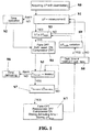
- step S1 If a response in the step S1 is NO, than the diagram flow goes to the time operating step S2 (alarm condition).
- a response in the operating step S1 is YES, then it is determined, in the operating step S3, if the pressure difference is higher than or equal to a threshold pressure difference.
- step S4 the air fans are put in an OFF or switched off condition, whereas the defrosting resistances are switched to an ON status or energized and the compressor is switched to an OFF condition.
- step S4 also flows the step S2 related to the time operation (alarm condition).
- step S4 From the step S4, the flow goes to the step S5, where the defrosting end temperature is measured.
- step S5 From the step S5 the flow goes, if the response is NO, to the time defrosting step S6.
- step S5 the flow goes to the step S7, where it is determined if the defrosting end temperature is higher than or equal to the set defrosting end temperature.
- step S7 If the response is YES, from the step S7 the flow goes to the step S'7, wherein the air fans are in an ON condition, the heating resistances are OFF, the compressor is ON and the defrosting time and also the value ⁇ P fsbrin are stored.
- step S8 it is determined if the defrosting time is different from the Target or desired defrosting time.
- the flow goes to the step S9, where is determined the pressure difference variation ⁇ P soglia .
- step S9 the flow goes to the step S3.
- step S8 If the response in the step S8 is NO, the flow returns to the pressure difference measuring step S1.
- the intelligent defrosting device performs, under the control of the inventive method, a series of control operations, followed by alarm signals related to the evaporator operation through the defrosting step, by using the operating logic arrangements disclosed hereinbelow.
- These logic means provide to perform a series of checking operations, followed by alarm signals, related to the evaporator operating status during the defrosting step.
- the following operation status of the following components is monitored: a) the air fans; b) the defrosting electric resistances (or other defrosting devices); c) any anomalous formations of ice at the end of the defrosting operation.
- the safety logic means will be operated in a case in which ⁇ P soglia > fan ⁇ P max , that is as the threshold ⁇ P, which varies in a convergence cycle, exceeds the maximum ⁇ P value which can be achieved by the air fan associated with a given exchange battery.
- the threshold value is never achieved, and accordingly the defrosting operation could not be actuated.
- Another case in which the threshold ⁇ P could not be achieved is when an excessively high defrosting Target time value is set.
- the inventive method will comprise the steps of:
- Figures 2 and 2A respectively show the two sides of the refrigerating apparatus including the sensor means of the inventive device.
- FIG. 2B shows the main hardware components of the intelligent defrosting device of the present invention.
- the arrow A shows the air flow
- the dashed semicircular line 101 shows a fan-coil assembly
- the letters T1, T2 and T3 show temperature sensors
- 102 shows a differential pressure measuring device
- 103 shows a pressure probe
- 104 shows a control panel
- the arrow F1 shows a power supply of the control panel 104
- the arrow F2 shows the output drive signal
- the reference T4 shows a further temperature sensor.
- FIGS 3 to 3B show further hardware components of the intelligent defrosting device according to the present invention.
- a main hardware component thereof is a screened pressure gauge assembly 105, advantageously using a membrane 106, for example consisting of a commercially available GORE-TEX ® material.
- the pressure gauge assembly 105 further comprises an anti-turbulence cover 107.
- FIGS 3A and 3B schematically show defrosting end sensors which has been generally indicated by the reference letters T4, T1, T2, T3.
- Figure 3B is a left side front view of Figure 3A .
- Figures 3A and 3B clearly show possible positions of the defrosting end sensors T4, T1, T2, T3, that is on a bend portion of the refrigerating circuit, at a top central position on the manifold side (0) and inside the finned pack at a diagonal position T1, T2, T3.
- FIGS 3, 3A and 3B also clearly show that the defrosting device 100 of the present invention comprises a small number of hardware components which, besides reducing the cost of the device, allow said device to be nearly free from maintenance.
- the invention has provided an "intelligent" defrosting method and an “intelligent” defrosting device, which may always perform the defrosting operation at an optimal defrosting time, thereby preventing the evaporator from operating in non-optimal operating conditions, that is with non-optimal performance coefficients of the refrigerating/heat pump cycle.
- a further advantage of the method and device according to the present invention is that the subject intelligent defrosting device may be applied to any type of evaporators, independently of their power or the refrigerating fluid used and the operating conditions thereof.
- Yet another advantage of the present invention is that the operator may change at will the defrosting cycle time preset value, based on the operator requirements.
- inventive method and device have been herein disclosed as used in air refrigerating and/or air conditioning apparatus, they could be obviously also used in other frost or ice forming apparatus, which ice, for an efficient and optimal operation of the apparatus, must be quickly removed, for example apparatus operating based on sucked air or air delivered on the exchange battery, as well as for any types of air fans (either of an axial or centrifugal type, and so on).
Priority Applications (1)
| Application Number | Priority Date | Filing Date | Title |
|---|---|---|---|
| RS20200342A RS60088B1 (sr) | 2015-04-20 | 2016-04-20 | Postupak odmrzavanja i uređaj za hlađenje ili aparat za klimatizaciju |
Applications Claiming Priority (1)
| Application Number | Priority Date | Filing Date | Title |
|---|---|---|---|
| ITMI2015A000564A ITMI20150564A1 (it) | 2015-04-20 | 2015-04-20 | Procedimento e dispositivo di sbrinatura, in particolare per apparecchi per la refrigerazione ed il condizionamento dell'aria |
Publications (2)
| Publication Number | Publication Date |
|---|---|
| EP3086060A1 true EP3086060A1 (fr) | 2016-10-26 |
| EP3086060B1 EP3086060B1 (fr) | 2020-01-29 |
Family
ID=53765290
Family Applications (1)
| Application Number | Title | Priority Date | Filing Date |
|---|---|---|---|
| EP16020148.9A Active EP3086060B1 (fr) | 2015-04-20 | 2016-04-20 | Procédé et appareil de degivrage pour appareil frigorifique ou climatiseur |
Country Status (6)
| Country | Link |
|---|---|
| EP (1) | EP3086060B1 (fr) |
| ES (1) | ES2775048T3 (fr) |
| HU (1) | HUE047831T2 (fr) |
| IT (1) | ITMI20150564A1 (fr) |
| PT (1) | PT3086060T (fr) |
| RS (1) | RS60088B1 (fr) |
Cited By (4)
| Publication number | Priority date | Publication date | Assignee | Title |
|---|---|---|---|---|
| CN107166741A (zh) * | 2017-06-19 | 2017-09-15 | 广东美的暖通设备有限公司 | 热泵机组及其防冻结控制方法 |
| CN107192206A (zh) * | 2017-06-29 | 2017-09-22 | 青岛海尔股份有限公司 | 一种冰箱的化霜方法 |
| NO20180682A1 (no) * | 2018-05-15 | 2019-06-11 | Romy Clima As | Fremgangsmåte for styring av en ventilasjonsvarmepumpe |
| CN111426109A (zh) * | 2020-03-16 | 2020-07-17 | 科希曼电器有限公司 | 基于温度及风压差检测的空气源热泵除霜系统以及方法 |
Citations (7)
| Publication number | Priority date | Publication date | Assignee | Title |
|---|---|---|---|---|
| US3299237A (en) * | 1964-03-02 | 1967-01-17 | Robertshaw Controls Co | Defroster control or the like |
| EP0147825A2 (fr) * | 1983-12-27 | 1985-07-10 | Honeywell Inc. | Système de régulation de dégivrage pour une pompe à chaleur |
| EP0881440A2 (fr) * | 1997-05-27 | 1998-12-02 | R.C. Condizionatori S.p.A. | Commande de dégivrage d'évaporateur pour une unité de pompe à chaleur à air |
| US6430985B1 (en) * | 1999-08-05 | 2002-08-13 | Johnson Controls Technology Company | Multiple point calibrated HVAC flow rate controller |
| US20040104278A1 (en) * | 2002-11-22 | 2004-06-03 | Walsh Paul J. | System and apparatus for refrigeration and heating |
| KR100685767B1 (ko) * | 2005-11-01 | 2007-02-22 | 주식회사 대우일렉트로닉스 | 폐열회수 환기장치의 제상운전 시스템 및 방법 |
| JP2011247525A (ja) * | 2010-05-28 | 2011-12-08 | Panasonic Corp | 冷凍装置 |
-
2015
- 2015-04-20 IT ITMI2015A000564A patent/ITMI20150564A1/it unknown
-
2016
- 2016-04-20 PT PT160201489T patent/PT3086060T/pt unknown
- 2016-04-20 EP EP16020148.9A patent/EP3086060B1/fr active Active
- 2016-04-20 HU HUE16020148A patent/HUE047831T2/hu unknown
- 2016-04-20 ES ES16020148T patent/ES2775048T3/es active Active
- 2016-04-20 RS RS20200342A patent/RS60088B1/sr unknown
Patent Citations (7)
| Publication number | Priority date | Publication date | Assignee | Title |
|---|---|---|---|---|
| US3299237A (en) * | 1964-03-02 | 1967-01-17 | Robertshaw Controls Co | Defroster control or the like |
| EP0147825A2 (fr) * | 1983-12-27 | 1985-07-10 | Honeywell Inc. | Système de régulation de dégivrage pour une pompe à chaleur |
| EP0881440A2 (fr) * | 1997-05-27 | 1998-12-02 | R.C. Condizionatori S.p.A. | Commande de dégivrage d'évaporateur pour une unité de pompe à chaleur à air |
| US6430985B1 (en) * | 1999-08-05 | 2002-08-13 | Johnson Controls Technology Company | Multiple point calibrated HVAC flow rate controller |
| US20040104278A1 (en) * | 2002-11-22 | 2004-06-03 | Walsh Paul J. | System and apparatus for refrigeration and heating |
| KR100685767B1 (ko) * | 2005-11-01 | 2007-02-22 | 주식회사 대우일렉트로닉스 | 폐열회수 환기장치의 제상운전 시스템 및 방법 |
| JP2011247525A (ja) * | 2010-05-28 | 2011-12-08 | Panasonic Corp | 冷凍装置 |
Cited By (7)
| Publication number | Priority date | Publication date | Assignee | Title |
|---|---|---|---|---|
| CN107166741A (zh) * | 2017-06-19 | 2017-09-15 | 广东美的暖通设备有限公司 | 热泵机组及其防冻结控制方法 |
| CN107166741B (zh) * | 2017-06-19 | 2019-10-01 | 广东美的暖通设备有限公司 | 热泵机组及其防冻结控制方法 |
| CN107192206A (zh) * | 2017-06-29 | 2017-09-22 | 青岛海尔股份有限公司 | 一种冰箱的化霜方法 |
| NO20180682A1 (no) * | 2018-05-15 | 2019-06-11 | Romy Clima As | Fremgangsmåte for styring av en ventilasjonsvarmepumpe |
| NO343798B1 (no) * | 2018-05-15 | 2019-06-11 | Romy Clima As | Fremgangsmåte for styring av en ventilasjonsvarmepumpe |
| WO2019221606A1 (fr) * | 2018-05-15 | 2019-11-21 | Romy Clima As | Procédé de commande d'une pompe à chaleur de ventilation |
| CN111426109A (zh) * | 2020-03-16 | 2020-07-17 | 科希曼电器有限公司 | 基于温度及风压差检测的空气源热泵除霜系统以及方法 |
Also Published As
| Publication number | Publication date |
|---|---|
| ES2775048T3 (es) | 2020-07-23 |
| RS60088B1 (sr) | 2020-05-29 |
| EP3086060B1 (fr) | 2020-01-29 |
| ITMI20150564A1 (it) | 2016-10-20 |
| PT3086060T (pt) | 2020-04-06 |
| HUE047831T2 (hu) | 2020-05-28 |
Similar Documents
| Publication | Publication Date | Title |
|---|---|---|
| EP3086060B1 (fr) | Procédé et appareil de degivrage pour appareil frigorifique ou climatiseur | |
| EP3051236B1 (fr) | Dispositif à cycle de congélation | |
| US20100011793A1 (en) | Refrigeration control system | |
| US20070295015A1 (en) | Method and apparatus for affecting defrost operations for a refrigeration system | |
| EP2679936A1 (fr) | Détection de défaut et diagnostic d'un réfrigérateur d'un capteur de compresseur | |
| US10533783B2 (en) | Air conditioner having compressor bypass and evaluation of volume of connecting pipe | |
| US10139815B2 (en) | Chiller control device, chiller, and chiller diagnostic method | |
| US20180335236A1 (en) | Air-conditioning apparatus | |
| CN105135628A (zh) | 空调器及空调器的除霜控制方法 | |
| CN102141334A (zh) | 制冷设备翅片结霜检测装置及其应用的自动化霜装置 | |
| JP2011247524A (ja) | 冷凍装置 | |
| GB2528213A (en) | Heat pump device and air-conditioning system | |
| EP2443404B1 (fr) | Appareil de commande et procede de commande de systemes de pompe a chaleur et de refrigeration | |
| EP3896354B1 (fr) | Appareil de climatisation | |
| KR101269068B1 (ko) | 중소형 저온저장고 운전 제어방법 | |
| JP2016065699A (ja) | 冷凍サイクル装置 | |
| KR20090067738A (ko) | 공기조화기의 제어방법 | |
| JP2008249226A (ja) | 冷凍装置の冷媒漏れ検出方法 | |
| JP2005042982A (ja) | 空気調和機 | |
| CN112824772B (zh) | 空调器及其除霜方法与装置 | |
| KR100707352B1 (ko) | 공기 조화기, 공기 조화기의 온도 센서의 고장 검출 방법및 공기 조화기의 온도 센서 제빙 방법 | |
| JP5657299B2 (ja) | 冷凍装置 | |
| CN117387248A (zh) | 一种热泵机组 | |
| JP5147497B2 (ja) | 冷凍装置または冷蔵装置の室内機、冷凍装置、冷蔵装置 | |
| CN116792984A (zh) | 一种热泵系统及其的除霜控制方法 |
Legal Events
| Date | Code | Title | Description |
|---|---|---|---|
| PUAI | Public reference made under article 153(3) epc to a published international application that has entered the european phase |
Free format text: ORIGINAL CODE: 0009012 |
|
| AK | Designated contracting states |
Kind code of ref document: A1 Designated state(s): AL AT BE BG CH CY CZ DE DK EE ES FI FR GB GR HR HU IE IS IT LI LT LU LV MC MK MT NL NO PL PT RO RS SE SI SK SM TR |
|
| AX | Request for extension of the european patent |
Extension state: BA ME |
|
| STAA | Information on the status of an ep patent application or granted ep patent |
Free format text: STATUS: REQUEST FOR EXAMINATION WAS MADE |
|
| 17P | Request for examination filed |
Effective date: 20170421 |
|
| STAA | Information on the status of an ep patent application or granted ep patent |
Free format text: STATUS: EXAMINATION IS IN PROGRESS |
|
| 17Q | First examination report despatched |
Effective date: 20180907 |
|
| REG | Reference to a national code |
Ref country code: DE Ref legal event code: R079 Ref document number: 602016028539 Country of ref document: DE Free format text: PREVIOUS MAIN CLASS: F25D0021000000 Ipc: F25D0021020000 |
|
| GRAP | Despatch of communication of intention to grant a patent |
Free format text: ORIGINAL CODE: EPIDOSNIGR1 |
|
| STAA | Information on the status of an ep patent application or granted ep patent |
Free format text: STATUS: GRANT OF PATENT IS INTENDED |
|
| GRAJ | Information related to disapproval of communication of intention to grant by the applicant or resumption of examination proceedings by the epo deleted |
Free format text: ORIGINAL CODE: EPIDOSDIGR1 |
|
| STAA | Information on the status of an ep patent application or granted ep patent |
Free format text: STATUS: EXAMINATION IS IN PROGRESS |
|
| RIC1 | Information provided on ipc code assigned before grant |
Ipc: F25D 21/02 20060101AFI20190912BHEP |
|
| GRAP | Despatch of communication of intention to grant a patent |
Free format text: ORIGINAL CODE: EPIDOSNIGR1 |
|
| STAA | Information on the status of an ep patent application or granted ep patent |
Free format text: STATUS: GRANT OF PATENT IS INTENDED |
|
| INTG | Intention to grant announced |
Effective date: 20190925 |
|
| INTC | Intention to grant announced (deleted) | ||
| INTG | Intention to grant announced |
Effective date: 20191023 |
|
| GRAS | Grant fee paid |
Free format text: ORIGINAL CODE: EPIDOSNIGR3 |
|
| GRAA | (expected) grant |
Free format text: ORIGINAL CODE: 0009210 |
|
| STAA | Information on the status of an ep patent application or granted ep patent |
Free format text: STATUS: THE PATENT HAS BEEN GRANTED |
|
| AK | Designated contracting states |
Kind code of ref document: B1 Designated state(s): AL AT BE BG CH CY CZ DE DK EE ES FI FR GB GR HR HU IE IS IT LI LT LU LV MC MK MT NL NO PL PT RO RS SE SI SK SM TR |
|
| REG | Reference to a national code |
Ref country code: GB Ref legal event code: FG4D |
|
| REG | Reference to a national code |
Ref country code: CH Ref legal event code: EP |
|
| REG | Reference to a national code |
Ref country code: AT Ref legal event code: REF Ref document number: 1228788 Country of ref document: AT Kind code of ref document: T Effective date: 20200215 |
|
| REG | Reference to a national code |
Ref country code: IE Ref legal event code: FG4D |
|
| REG | Reference to a national code |
Ref country code: DE Ref legal event code: R096 Ref document number: 602016028539 Country of ref document: DE |
|
| REG | Reference to a national code |
Ref country code: SE Ref legal event code: TRGR |
|
| REG | Reference to a national code |
Ref country code: NL Ref legal event code: FP |
|
| REG | Reference to a national code |
Ref country code: PT Ref legal event code: SC4A Ref document number: 3086060 Country of ref document: PT Date of ref document: 20200406 Kind code of ref document: T Free format text: AVAILABILITY OF NATIONAL TRANSLATION Effective date: 20200330 |
|
| REG | Reference to a national code |
Ref country code: RO Ref legal event code: EPE |
|
| REG | Reference to a national code |
Ref country code: HU Ref legal event code: AG4A Ref document number: E047831 Country of ref document: HU |
|
| REG | Reference to a national code |
Ref country code: ES Ref legal event code: FG2A Ref document number: 2775048 Country of ref document: ES Kind code of ref document: T3 Effective date: 20200723 |
|
| PG25 | Lapsed in a contracting state [announced via postgrant information from national office to epo] |
Ref country code: FI Free format text: LAPSE BECAUSE OF FAILURE TO SUBMIT A TRANSLATION OF THE DESCRIPTION OR TO PAY THE FEE WITHIN THE PRESCRIBED TIME-LIMIT Effective date: 20200129 Ref country code: NO Free format text: LAPSE BECAUSE OF FAILURE TO SUBMIT A TRANSLATION OF THE DESCRIPTION OR TO PAY THE FEE WITHIN THE PRESCRIBED TIME-LIMIT Effective date: 20200429 |
|
| REG | Reference to a national code |
Ref country code: LT Ref legal event code: MG4D |
|
| PG25 | Lapsed in a contracting state [announced via postgrant information from national office to epo] |
Ref country code: GR Free format text: LAPSE BECAUSE OF FAILURE TO SUBMIT A TRANSLATION OF THE DESCRIPTION OR TO PAY THE FEE WITHIN THE PRESCRIBED TIME-LIMIT Effective date: 20200430 Ref country code: IS Free format text: LAPSE BECAUSE OF FAILURE TO SUBMIT A TRANSLATION OF THE DESCRIPTION OR TO PAY THE FEE WITHIN THE PRESCRIBED TIME-LIMIT Effective date: 20200529 Ref country code: BG Free format text: LAPSE BECAUSE OF FAILURE TO SUBMIT A TRANSLATION OF THE DESCRIPTION OR TO PAY THE FEE WITHIN THE PRESCRIBED TIME-LIMIT Effective date: 20200429 Ref country code: HR Free format text: LAPSE BECAUSE OF FAILURE TO SUBMIT A TRANSLATION OF THE DESCRIPTION OR TO PAY THE FEE WITHIN THE PRESCRIBED TIME-LIMIT Effective date: 20200129 Ref country code: LV Free format text: LAPSE BECAUSE OF FAILURE TO SUBMIT A TRANSLATION OF THE DESCRIPTION OR TO PAY THE FEE WITHIN THE PRESCRIBED TIME-LIMIT Effective date: 20200129 |
|
| PG25 | Lapsed in a contracting state [announced via postgrant information from national office to epo] |
Ref country code: DK Free format text: LAPSE BECAUSE OF FAILURE TO SUBMIT A TRANSLATION OF THE DESCRIPTION OR TO PAY THE FEE WITHIN THE PRESCRIBED TIME-LIMIT Effective date: 20200129 Ref country code: LT Free format text: LAPSE BECAUSE OF FAILURE TO SUBMIT A TRANSLATION OF THE DESCRIPTION OR TO PAY THE FEE WITHIN THE PRESCRIBED TIME-LIMIT Effective date: 20200129 Ref country code: CZ Free format text: LAPSE BECAUSE OF FAILURE TO SUBMIT A TRANSLATION OF THE DESCRIPTION OR TO PAY THE FEE WITHIN THE PRESCRIBED TIME-LIMIT Effective date: 20200129 Ref country code: EE Free format text: LAPSE BECAUSE OF FAILURE TO SUBMIT A TRANSLATION OF THE DESCRIPTION OR TO PAY THE FEE WITHIN THE PRESCRIBED TIME-LIMIT Effective date: 20200129 Ref country code: SM Free format text: LAPSE BECAUSE OF FAILURE TO SUBMIT A TRANSLATION OF THE DESCRIPTION OR TO PAY THE FEE WITHIN THE PRESCRIBED TIME-LIMIT Effective date: 20200129 Ref country code: SK Free format text: LAPSE BECAUSE OF FAILURE TO SUBMIT A TRANSLATION OF THE DESCRIPTION OR TO PAY THE FEE WITHIN THE PRESCRIBED TIME-LIMIT Effective date: 20200129 |
|
| REG | Reference to a national code |
Ref country code: DE Ref legal event code: R097 Ref document number: 602016028539 Country of ref document: DE |
|
| REG | Reference to a national code |
Ref country code: AT Ref legal event code: MK05 Ref document number: 1228788 Country of ref document: AT Kind code of ref document: T Effective date: 20200129 |
|
| PG25 | Lapsed in a contracting state [announced via postgrant information from national office to epo] |
Ref country code: MC Free format text: LAPSE BECAUSE OF FAILURE TO SUBMIT A TRANSLATION OF THE DESCRIPTION OR TO PAY THE FEE WITHIN THE PRESCRIBED TIME-LIMIT Effective date: 20200129 |
|
| REG | Reference to a national code |
Ref country code: CH Ref legal event code: PL |
|
| PLBE | No opposition filed within time limit |
Free format text: ORIGINAL CODE: 0009261 |
|
| STAA | Information on the status of an ep patent application or granted ep patent |
Free format text: STATUS: NO OPPOSITION FILED WITHIN TIME LIMIT |
|
| REG | Reference to a national code |
Ref country code: HU Ref legal event code: HC9C Owner name: LU-VE S.P.A., IT |
|
| 26N | No opposition filed |
Effective date: 20201030 |
|
| PG25 | Lapsed in a contracting state [announced via postgrant information from national office to epo] |
Ref country code: CH Free format text: LAPSE BECAUSE OF NON-PAYMENT OF DUE FEES Effective date: 20200430 Ref country code: LI Free format text: LAPSE BECAUSE OF NON-PAYMENT OF DUE FEES Effective date: 20200430 Ref country code: LU Free format text: LAPSE BECAUSE OF NON-PAYMENT OF DUE FEES Effective date: 20200420 Ref country code: AT Free format text: LAPSE BECAUSE OF FAILURE TO SUBMIT A TRANSLATION OF THE DESCRIPTION OR TO PAY THE FEE WITHIN THE PRESCRIBED TIME-LIMIT Effective date: 20200129 |
|
| PG25 | Lapsed in a contracting state [announced via postgrant information from national office to epo] |
Ref country code: PL Free format text: LAPSE BECAUSE OF FAILURE TO SUBMIT A TRANSLATION OF THE DESCRIPTION OR TO PAY THE FEE WITHIN THE PRESCRIBED TIME-LIMIT Effective date: 20200129 Ref country code: SI Free format text: LAPSE BECAUSE OF FAILURE TO SUBMIT A TRANSLATION OF THE DESCRIPTION OR TO PAY THE FEE WITHIN THE PRESCRIBED TIME-LIMIT Effective date: 20200129 |
|
| PG25 | Lapsed in a contracting state [announced via postgrant information from national office to epo] |
Ref country code: IE Free format text: LAPSE BECAUSE OF NON-PAYMENT OF DUE FEES Effective date: 20200420 |
|
| PGFP | Annual fee paid to national office [announced via postgrant information from national office to epo] |
Ref country code: RO Payment date: 20210413 Year of fee payment: 6 |
|
| PG25 | Lapsed in a contracting state [announced via postgrant information from national office to epo] |
Ref country code: MT Free format text: LAPSE BECAUSE OF FAILURE TO SUBMIT A TRANSLATION OF THE DESCRIPTION OR TO PAY THE FEE WITHIN THE PRESCRIBED TIME-LIMIT Effective date: 20200129 Ref country code: CY Free format text: LAPSE BECAUSE OF FAILURE TO SUBMIT A TRANSLATION OF THE DESCRIPTION OR TO PAY THE FEE WITHIN THE PRESCRIBED TIME-LIMIT Effective date: 20200129 |
|
| PG25 | Lapsed in a contracting state [announced via postgrant information from national office to epo] |
Ref country code: MK Free format text: LAPSE BECAUSE OF FAILURE TO SUBMIT A TRANSLATION OF THE DESCRIPTION OR TO PAY THE FEE WITHIN THE PRESCRIBED TIME-LIMIT Effective date: 20200129 Ref country code: AL Free format text: LAPSE BECAUSE OF FAILURE TO SUBMIT A TRANSLATION OF THE DESCRIPTION OR TO PAY THE FEE WITHIN THE PRESCRIBED TIME-LIMIT Effective date: 20200129 |
|
| REG | Reference to a national code |
Ref country code: HU Ref legal event code: HC9C Owner name: LU-VE S.P.A., IT |
|
| PG25 | Lapsed in a contracting state [announced via postgrant information from national office to epo] |
Ref country code: RO Free format text: LAPSE BECAUSE OF NON-PAYMENT OF DUE FEES Effective date: 20220420 |
|
| P01 | Opt-out of the competence of the unified patent court (upc) registered |
Effective date: 20230310 |
|
| P02 | Opt-out of the competence of the unified patent court (upc) changed |
Effective date: 20230502 |
|
| PGFP | Annual fee paid to national office [announced via postgrant information from national office to epo] |
Ref country code: NL Payment date: 20230426 Year of fee payment: 8 |
|
| PGFP | Annual fee paid to national office [announced via postgrant information from national office to epo] |
Ref country code: RS Payment date: 20230418 Year of fee payment: 8 Ref country code: PT Payment date: 20230418 Year of fee payment: 8 Ref country code: IT Payment date: 20230426 Year of fee payment: 8 Ref country code: FR Payment date: 20230418 Year of fee payment: 8 Ref country code: ES Payment date: 20230529 Year of fee payment: 8 Ref country code: DE Payment date: 20230421 Year of fee payment: 8 |
|
| PGFP | Annual fee paid to national office [announced via postgrant information from national office to epo] |
Ref country code: TR Payment date: 20230419 Year of fee payment: 8 Ref country code: SE Payment date: 20230424 Year of fee payment: 8 Ref country code: HU Payment date: 20230419 Year of fee payment: 8 |
|
| PGFP | Annual fee paid to national office [announced via postgrant information from national office to epo] |
Ref country code: BE Payment date: 20230428 Year of fee payment: 8 |
|
| PGFP | Annual fee paid to national office [announced via postgrant information from national office to epo] |
Ref country code: GB Payment date: 20230418 Year of fee payment: 8 |
|
| PGFP | Annual fee paid to national office [announced via postgrant information from national office to epo] |
Ref country code: RO Payment date: 20240110 Year of fee payment: 8 Ref country code: RO Payment date: 20240110 Year of fee payment: 7 |