EP3085864B1 - Dispositif de fermeture pour une porte ou une trappe - Google Patents
Dispositif de fermeture pour une porte ou une trappe Download PDFInfo
- Publication number
- EP3085864B1 EP3085864B1 EP16165727.5A EP16165727A EP3085864B1 EP 3085864 B1 EP3085864 B1 EP 3085864B1 EP 16165727 A EP16165727 A EP 16165727A EP 3085864 B1 EP3085864 B1 EP 3085864B1
- Authority
- EP
- European Patent Office
- Prior art keywords
- screw
- cylinder liner
- closing device
- bracket
- cylinder
- Prior art date
- Legal status (The legal status is an assumption and is not a legal conclusion. Google has not performed a legal analysis and makes no representation as to the accuracy of the status listed.)
- Active
Links
Images

Classifications
-
- E—FIXED CONSTRUCTIONS
- E05—LOCKS; KEYS; WINDOW OR DOOR FITTINGS; SAFES
- E05B—LOCKS; ACCESSORIES THEREFOR; HANDCUFFS
- E05B9/00—Lock casings or latch-mechanism casings ; Fastening locks or fasteners or parts thereof to the wing
- E05B9/08—Fastening locks or fasteners or parts thereof, e.g. the casings of latch-bolt locks or cylinder locks to the wing
- E05B9/084—Fastening of lock cylinders, plugs or cores
-
- E—FIXED CONSTRUCTIONS
- E05—LOCKS; KEYS; WINDOW OR DOOR FITTINGS; SAFES
- E05B—LOCKS; ACCESSORIES THEREFOR; HANDCUFFS
- E05B79/00—Mounting or connecting vehicle locks or parts thereof
- E05B79/02—Mounting of vehicle locks or parts thereof
-
- E—FIXED CONSTRUCTIONS
- E05—LOCKS; KEYS; WINDOW OR DOOR FITTINGS; SAFES
- E05B—LOCKS; ACCESSORIES THEREFOR; HANDCUFFS
- E05B63/00—Locks or fastenings with special structural characteristics
- E05B63/0056—Locks with adjustable or exchangeable lock parts
-
- E—FIXED CONSTRUCTIONS
- E05—LOCKS; KEYS; WINDOW OR DOOR FITTINGS; SAFES
- E05B—LOCKS; ACCESSORIES THEREFOR; HANDCUFFS
- E05B85/00—Details of vehicle locks not provided for in groups E05B77/00 - E05B83/00
- E05B85/06—Lock cylinder arrangements
Definitions
- the invention relates to a closing device for a door or flap, in particular a vehicle, preferably a motor vehicle, with a cylinder lock having a cylinder liner and a cylinder core rotatably mounted in the cylinder core, with a fastened to the door or flap bearing bracket, a receptacle has for the cylinder lock, and with a screw which produces a mechanical connection of the cylinder liner with a cladding element of the closing device for the door or flap, wherein the cylinder liner at least partially radially embracing bracket member is provided which is slidably mounted on the bearing bracket and the has at least one engagement means for engaging in a recess of the cylinder liner.
- Locking devices of the type mentioned are of the prior art, for example from the DE 10 2004 012 456 A1 known.
- measures to increase theft or breakdown safety of vehicles In addition to electronic devices, such as immobilizers, this also mechanical devices are used.
- mechanical safety devices closing devices are common, which comprise a arranged in a door or a flap of the vehicle cylinder lock.
- the cylinder lock has as essential components on a particular stationary cylinder liner which is fixed to the bearing bracket and in which a cylinder core is rotatably mounted.
- the cylinder lock is usually held in a bearing bracket, which is fixed inside the door or flap or on the inside. From the DE 10 2004 012 456 A1 It is also known to provide a screw which establishes a mechanical connection of the cylinder liner with a trim panel of the door or flap. For this purpose, the screw is inserted from outside through the cladding sheet and through the bearing bracket in a radial recess of the cylinder liner partially.
- a door handle system which has a torsion bar, which is formed in a single-ended V-shaped to allow an arrangement of the torsion bar both when mounted on a left side of the vehicle and on the right side of the vehicle.
- the screw is provided, which only fulfills its function in the event of a violent breakup. Due to the large number of items a relatively large amount of space is required and there are also correspondingly high manufacturing and assembly costs.
- the invention is therefore an object of the invention to provide a locking device which is less expensive and space-saving, without sacrificing security against breakage, and wherein an adjustment of the locking device is adaptable to different conditions.
- the object underlying the invention is achieved by a locking device with the features of claim 1.
- This has the advantage that only a single screw is provided both for the attachment of the cylinder liner in the bearing bracket and for securing to the cladding element, which assumes both the function of attachment and the function of the fuse.
- the cladding element is a cladding panel, more preferably an inner panel of the door or flap.
- the cladding element is doing a part of the locking device. Due to the fact that at least two threaded holes on the Ironing element are provided, and correspondingly also at least two radial recesses on the cylinder liner, one of which is associated with one of the threaded holes, is also achieved that different positions for the screw for fixing the cylinder liner are available.
- This has in particular in relation to the cladding element and provided thereon / seals formed the advantage that the closing device according to the invention can be used on doors with different gradients of the seals and / or the cladding elements in total, with at least two different Verschraubungsmother the screw into each better suitable position, in particular with respect to the course of the seal and / or the cladding element can be arranged.
- the inventive solution which also reduces manufacturing costs.
- the locking device is characterized in that the screw cooperates with one of at least two threaded holes of the bracket member to its displacement, wherein the cylinder liner assigned to each of the threaded holes or assignable each having a radial recess which forms a pressure surface, and wherein the screw on her Cylinder socket facing the end has a pressure peak, which is introduced into the respective radial recess / and cooperates with the pressure surface for axial and radial support of the screw.
- the locking device thus has only one screw for fastening and securing the cylinder lock or the cylinder liner.
- the screw is guided by a thread of the bracket element or by one of the threaded holes. By a rotation of the screw can be moved axially with respect to the bracket element.
- the bracket element can be moved in a spindle-like manner and, in particular, with the at least one engagement means, be brought into engagement with the recess of the cylinder liner in order to fasten it in the bearing bracket.
- the at least one engagement means on the opposite side of the threaded holes of the bracket element, that is arranged in a cylinder bushing behind engaging portion of the bracket member.
- the strap member thus engages around the cylinder liner radially so far that it engages behind the cylinder liner at least partially - from the perspective of Gewindebohrung-. Since the screw at the same time makes mechanical connection to the cladding element, the screw fulfills both of the above functions.
- the screw is supported on the cylinder liner to relocate the stirrup element and at the same time is in mechanical connection with the trim element to ensure the described entanglement in the event of a violent breakage of the closure device.
- the screw is thus the only screw for fastening and securing the locking device or the cylinder lock.
- the locking device can advantageously be arranged and used on different doors or flaps -as already mentioned above.
- the bracket element is at least substantially annular and engages the cylinder liner completely radially.
- the bracket member thus encloses the cylinder liner completely and has due to the continuous ring shape a particularly high stability against mechanical breakage.
- the security against unauthorized opening of the door or flap is further increased.
- the threaded holes are formed side by side on one side of the bracket element.
- the threaded bores are distributed in the longitudinal extent of the cylinder, in particular evenly distributed.
- the threaded axes of the threaded holes are aligned parallel to each other.
- the threaded axes are aligned parallel to the direction of the ironing element.
- the bracket element has on the opposite side of the threaded bores a crosspiece as engaging means.
- the crossbar connects two parallel and spaced apart legs of the bracket element at their free ends together, whereby the closed ring shape is formed and the high burglar resistance is ensured.
- the fact that the transverse web itself forms the engagement means no further precautions to the bracket element are necessary, such as radially inwardly projecting engagement projections, so that the bracket element is particularly inexpensive and easy to produce.
- one or more projections pointing radially inward or in the direction of the cylinder liner are provided on the transverse web, which engage in corresponding receptacles.
- the cylinder liner on its side opposite the radial recess side has the recess for receiving the or the engagement means.
- the recess of the cylinder liner is associated with the engagement means of the bracket element, which lies on the opposite side of the threaded holes. On the one hand this prevents incorrect assembly, and on the other hand, the introduction of the or the engagement means in the recess by the support of the screw on the pressure surface of the cylinder liner is thereby optimally possible.
- the recess is formed as a receiving groove in the cylinder liner.
- the receiving groove for receiving the cross bar is formed, wherein the receiving groove preferably extends only over a limited circumferential angle of the cylinder liner.
- the transverse web and / or the receiving groove each have at least one Ein Industriesfase that ensures a safe insertion of the bracket element in the recess of the cylinder liner and an automatic centering of the cylinder liner.
- the bearing bracket has a sliding guide for at least substantially only radially with respect to the cylinder liner displaceable arrangement of the bracket member.
- the pressure surface of the respective radial recess is conical, wherein the pressure peak of the screw is formed complementary to the pressure surface. This ensures that a flat support of the pressure peak is ensured in the radial recess or on the pressure surface for advantageous power transmission.
- the conical training is also an automatic Centering of the screw or its pressure peak reached, wherein in the screwed or introduced into the radial recess state on the pressure peak of the screw forces can also be transmitted radially relative to the screw on the bracket element and vice versa.
- the bracket element has a first cylinder bushing engaging portion and a second, the threaded holes having portion, wherein the two portions are at least substantially perpendicular to each other.
- the cladding element has an opening through which the screw is passed with its opposite end of the pressure tip.
- the hooking of the cylinder liner to the cladding element is ensured in the event of a violent break-up of the closing device in a simple manner.
- the diameter of the invention almost corresponds to the diameter of a threaded shaft of the screw to ensure a secure hooking.
- the screw has a screw head whose diameter is greater than the diameter of the opening of the cladding element, wherein the screw head is located on the opposite side of the cleat element of the cladding element, so advantageously by the screw head an additional positive locking is ensured against unauthorized breaking the locking device.
- FIG. 1 shows a fragmentary door 1 of a motor vehicle, not shown, which has a closing device 2, in a sectional view.
- a bearing bracket 3 of the locking device 2 is fixed, which also carries an actuable door handle 4.
- the bearing bracket 3 further has a receptacle 5, in which a cylinder lock 6 is arranged.
- the cylinder lock 6 has a cylinder bushing 7 and a cylinder core 8 which is rotatably mounted in the cylinder bushing.
- the rotation of the cylinder core 8 can only be triggered with a corresponding key inserted into the core.
- the basic design of a cylinder lock is known from the prior art and will therefore not be explained in detail here.
- the cylinder liner 7 is inserted axially into the receptacle 5 and held at least radially positive fit by the receptacle 5.
- the cylinder lock 6 is further associated with a bracket member 9, which serves for the axial fixation of the cylinder liner 7 and thus of the cylinder lock 6 in the receptacle 5 and on the bearing bracket 3. Furthermore, the closure device 2 has a screw 10, which cooperates with the bracket element 9, as described below.
- the screw 10 can be arranged in two different positions P1 and P2, wherein a first position P1 by solid lines and a second position P2 by dashed lines in FIG. 1 are shown.
- FIG. 2 shows an enlarged detail view of the locking device 2 in a further sectional view. It shows FIG. 2 a detailed view of the first position P1 of the screw 10, wherein the formation of the locking device 2 is repeated relative to the position P1 in the position P2, so that the following description also applies to the formation of the locking device 2 in the region of the position P2.
- the screw 10 has at one end a screw head 11, to which a threaded shaft 12 connects, the other end in a Pressure peak 13 ends.
- the threaded shaft 12 has an external thread 14 which cooperates with an internal thread 15 of a threaded bore 16 of the bracket element 9.
- the pressure peak 13 has a conical contour and is designed to cooperate with a pressure surface 17, which is formed by a radial recess 18 of the cylinder liner 7.
- the pressure surface 17 has a conicity complementary to the pressure peak 13, so that the pressure peak 13 rests flat against the pressure surface 17, so that both axially and radially - with respect to the screw 10 - forces can be transmitted.
- the closing device 2 at a distance from the threaded bore 16 has a further threaded bore 16 in the bracket element 9 which is offset in the longitudinal direction of the cylinder sleeve 7 to the first threaded bore 16.
- the further threaded bore 16 is associated with a further radial recess 18 in the cylinder liner 7, which, as described above, cooperates with the pressure peak 13 of the screw 10.
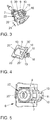
- FIG. 3 shows the cylinder lock 6 together with the bracket member 9 and the screw 10 in a perspective view. It can be seen that the bracket member 9 has a first portion 19 which includes the threaded holes 16 for the screw 10, and a second portion 20 which radially surrounds the cylinder liner 7 of the cylinder lock 6.
- FIG. 4 shows the bracket member 9 together with the screw 10 in a further perspective view, from which it will be apparent that the bracket member 9 is formed substantially annular with a rectangular contour.
- the bracket element 9 starting from the section 19 in the section 20, has two legs 20 'and 20 "arranged parallel to one another and spaced apart from each other, which are connected to one another at their free ends by a transverse web 20'''
- the first portion 19 is aligned substantially perpendicular to the second portion 20, wherein the threaded holes 16, through which the screw 10 is guided with its threaded shank 12, at the level of the crosspiece 20 '.
- the further threaded bore 16 is offset at a height to the transverse web 20'.
- the two taps ments 16 both equally spaced from the height of the transverse web 20 '''in the section 19 are formed. It is particularly preferred that the bracket element 9 two of the transverse webs 20 ''', which are each at the level of one of the threaded bores 16.
- the two legs 20 'and 20 "and the crossbar 20''' and the portion 19 are forming an opening of the bracket element respectively spaced so far from each other that the cylinder liner 7, as indicated by an arrow 21 in FIG. 3 indicated by the opening of the bracket member 9 through or hineinschiebbar.
- the cylinder liner 7 has on its radial recess 18 opposite side of a recess 22 in the form of a receiving groove 23, as best in FIG. 1 seen.
- the receiving groove 23 has a height or clear width, which substantially corresponds to the height of the transverse web 20 ''', so that it is preferably inserted into the receiving groove 23 without play, as in FIGS. 1 and 3 shown.
- the receiving groove 23 preferably extends only over the rear side or the radial recess 18 opposite side of the cylinder liner. 7
- FIG. 5 shows a plan view of the assembly of cylinder lock 6 and bracket member 9 and screw 10 according to FIG. 3 in the assembled state.
- the bracket member 9 is positioned in the bearing bracket 3.
- the bearing bracket 3 on a sliding guide 24, by which the bracket member 9 is mounted radially in the plane of the portion 20 radially relative to the cylinder liner 7 slidably.
- the cylinder lock 6 is inserted into the receptacle 5 and through the opening of the preassembled bracket element 9, as indicated by arrow 21.
- FIG. 1 shows in the embodiment, a first cladding element and dashed as an alternative a second cladding element 26 '.
- the cladding elements 26 and 26 ' differ in their shape and are optimally adapted, for example, to a body of the motor vehicle having the door 1 with respect to a sealing effect.
- the screw 10 is guided to the position P1 or the position P2.
- cladding elements 26, 26 ' may be required that depending on the position in which the screw 10 is to be arranged, a screw shank of the screw 10 must be designed to be different lengths, so that the screw head 11 of the screw 10, the respective cladding element 26th , 26 'can reach behind.
- the pressure peak 13 comes into contact with the rear surface 17, an axial force is exerted, by which the bracket member 9 is pulled in the direction of the screw head 11 on the threaded shaft 12 in a spindle-like manner.
- the transverse web 20 ''' is inserted into the receiving groove 23 of the cylinder liner 7.
- the cylinder lock 6 is fastened in a simple manner to the bearing bracket 3 or the door 1.
- the threaded shaft 12 of the screw 10 is passed through an opening 25 of the lining element 26 of the door 1, which is in particular designed as an inner plate, so that the screw head 11 is outside of the cladding element 26, while the rest of the closing device 2 inside the cladding element 26 is arranged.
- the screw head 11 in this case has an outer diameter which is larger than that of the opening 25.
- the closing device 2 is designed such that the screw head 11 is also outside of the cladding element 26 when the screw 10 has been screwed into the maximum threaded bore 16.
- the screw 10 thus fulfills two functions simultaneously, on the one hand the fastening of the cylinder lock 6 and on the other the securing of the cylinder lock 6 at a break of the closing device 2, wherein the fact that the screw 10 can be used in different positions P1, P2, an adaptation the closing device 2 to different conditions, in particular to different installation space conditions / conditions is adaptable, as described with reference to the differently shaped cladding elements 26, 26 '.
- the described closure device 2 is also arranged on a vehicle flap, such as a boot lid or the like.
Landscapes
- Engineering & Computer Science (AREA)
- Mechanical Engineering (AREA)
- Lock And Its Accessories (AREA)
- Power-Operated Mechanisms For Wings (AREA)
Claims (10)
- Dispositif de fermeture (2) pour une porte (1) ou une trappe, en particulier pour un véhicule, avec une serrure à cylindre (6) qui présente une chemise de cylindre (7) et un noyau de cylindre (8) supporté à rotation dans la chemise de cylindre (7), avec un étrier de palier (3) fixé ou pouvant être fixé à la porte (1) ou à la trappe, qui présente un logement (5) pour la serrure à cylindre (6) et avec une vis (10), qui établit une liaison mécanique de la chemise de cylindre (7) avec un élément d'habillage (26) du dispositif de fermeture pour la porte (1) ou la trappe, un élément d'étrier (9) venant en prise radialement au moins en partie autour de la chemise de cylindre (7) étant prévu, lequel est disposé de manière supportée de manière déplaçable sur l'étrier de palier (3) et présente au moins un moyen d'engagement (20''') pour l'engagement dans un évidement (22) de la chemise de cylindre (7), caractérisé en ce que la vis (10) coopère avec un d'au moins deux alésages filetés (16) de l'élément d'étrier (9) en vue de son déplacement, la chemise de cylindre (7) présentant un renfoncement radial (18) à chaque fois associé à chacun des alésages filetés (16), qui forme une surface de pression (17), la vis (10) présentant, au niveau de son extrémité tournée vers la chemise de cylindre (7), une pointe de pression (13) qui est introduite dans le renfoncement radial respectif (18) et coopère avec la surface de pression (17) en vue du support axial et radial de la vis (10).
- Dispositif de fermeture selon la revendication 1, caractérisé en ce que l'élément d'étrier (9) est réalisé au moins sensiblement sous forme annulaire et vient en prise radialement complètement autour de la chemise de cylindre (7).
- Dispositif de fermeture selon l'une quelconque des revendications précédentes, caractérisé en ce que l'élément d'étrier (9) présente en tant que moyen d'engagement, une nervure transversale (20''') du côté opposé aux alésages filetés (16).
- Dispositif de fermeture selon l'une quelconque des revendications précédentes, caractérisé en ce que la chemise de cylindre (7) présente l'évidement (22) sur son côté opposé au renfoncement radial (18).
- Dispositif de fermeture selon l'une quelconque des revendications précédentes, caractérisé en ce que l'évidement (22) est réalisé sous forme de rainure de réception (23) dans la chemise de cylindre (7).
- Dispositif de fermeture selon l'une quelconque des revendications précédentes, caractérisé en ce que la surface de pression (17) du renfoncement radial (18) est réalisée sous forme conique, la pointe de pression (13) de la vis (10) étant réalisée de manière complémentaire à la surface de pression (17).
- Dispositif de fermeture selon l'une quelconque des revendications précédentes, caractérisé en ce que l'élément d'étrier (9) présente une première portion (20) venant en prise autour de la chemise de cylindre (7) et une deuxième portion (19) présentant les alésages filetés (16), les deux portions (20, 19) étant orientées au moins sensiblement perpendiculairement l'une à l'autre.
- Dispositif de fermeture selon l'une quelconque des revendications précédentes, caractérisé en ce que l'étrier de palier (3) présente un guide coulissant (24) pour le positionnement de l'élément d'étrier (9) de manière déplaçable au moins sensiblement uniquement radialement par rapport à la chemise de cylindre (7).
- Dispositif de fermeture selon l'une quelconque des revendications précédentes, caractérisé en ce que l'élément d'habillage (26) présente une ouverture (25) à travers laquelle est guidée la vis (10).
- Dispositif de fermeture selon la revendication 9, caractérisé en ce que la vis (10) présente une tête de vis (11) dont le diamètre est supérieur au diamètre de l'ouverture (25) de l'élément d'habillage (26).
Applications Claiming Priority (1)
| Application Number | Priority Date | Filing Date | Title |
|---|---|---|---|
| DE102015207475.7A DE102015207475A1 (de) | 2015-04-23 | 2015-04-23 | Schließeinrichtung für eine Tür oder Klappe |
Publications (2)
| Publication Number | Publication Date |
|---|---|
| EP3085864A1 EP3085864A1 (fr) | 2016-10-26 |
| EP3085864B1 true EP3085864B1 (fr) | 2017-12-20 |
Family
ID=55755506
Family Applications (1)
| Application Number | Title | Priority Date | Filing Date |
|---|---|---|---|
| EP16165727.5A Active EP3085864B1 (fr) | 2015-04-23 | 2016-04-18 | Dispositif de fermeture pour une porte ou une trappe |
Country Status (2)
| Country | Link |
|---|---|
| EP (1) | EP3085864B1 (fr) |
| DE (1) | DE102015207475A1 (fr) |
Families Citing this family (2)
| Publication number | Priority date | Publication date | Assignee | Title |
|---|---|---|---|---|
| US10196842B2 (en) * | 2014-06-20 | 2019-02-05 | Huf North America Automotive Parts Manufacturing Corp. | Retention mechanism for insertion member in vehicular door handle assembly |
| DE102018220205A1 (de) * | 2018-11-23 | 2020-05-28 | Volkswagen Aktiengesellschaft | Schließsystem für eine Tür oder Klappe eines Kraftfahrzeugs, Tür oder Klappe eines Kraftfahrzeugs, Kraftfahrzeug |
Family Cites Families (8)
| Publication number | Priority date | Publication date | Assignee | Title |
|---|---|---|---|---|
| GB8701875D0 (en) * | 1987-01-28 | 1987-03-04 | Rolls Royce Motor Cars | Handle assembly |
| DE19845393C2 (de) | 1998-10-02 | 2000-08-31 | Daimler Chrysler Ag | Öffnungsvorrichtung für eine Fahrzeugtür |
| FR2789426B1 (fr) * | 1999-02-05 | 2001-06-15 | Valeo Securite Habitacle | Poignee d'ouvrant de vehicule automobile |
| DE20016108U1 (de) * | 2000-09-16 | 2001-01-18 | Kiekert Ag | Türbetätigungsaggregat für insbesondere Kraftfahrzeuge |
| DE102004012456B4 (de) | 2004-03-10 | 2019-05-09 | Volkswagen Ag | Schließeinrichtung eines Kraftfahrzeuges |
| DE102005042350A1 (de) * | 2005-09-07 | 2007-03-15 | Huf Hülsbeck & Fürst Gmbh & Co. Kg | Schließzylinder für insbesondere an Fahrzeugen vollziehbare Funktionen |
| DE102012112520A1 (de) | 2012-12-18 | 2014-06-18 | Dr. Ing. H.C. F. Porsche Aktiengesellschaft | Türaußengriffsystem bei einem Kraftfahrzeug |
| DE102013222465A1 (de) * | 2013-11-06 | 2015-05-07 | Volkswagen Aktiengesellschaft | Schließeinrichtung für eine Tür oder Klappe |
-
2015
- 2015-04-23 DE DE102015207475.7A patent/DE102015207475A1/de not_active Withdrawn
-
2016
- 2016-04-18 EP EP16165727.5A patent/EP3085864B1/fr active Active
Non-Patent Citations (1)
| Title |
|---|
| None * |
Also Published As
| Publication number | Publication date |
|---|---|
| EP3085864A1 (fr) | 2016-10-26 |
| DE102015207475A1 (de) | 2016-10-27 |
Similar Documents
| Publication | Publication Date | Title |
|---|---|---|
| EP3066282B1 (fr) | Moyen de fermeture d'une porte ou d'un ouvrant | |
| DE69824071T2 (de) | Lenksäulenverriegelung | |
| DE102007047860B3 (de) | Verbindungselement mit einer Schraube und einer daran unverlierbar angeordneten Hülse | |
| DE69922373T2 (de) | Verschlussvorrichtung und haubenschloss für ein fahrzeug mit einer derartigen verschlussvorrichtung | |
| DE102012112520A1 (de) | Türaußengriffsystem bei einem Kraftfahrzeug | |
| EP0636798B1 (fr) | Elément de fixation rotatif | |
| DE3223778C2 (fr) | ||
| EP2868850A1 (fr) | Cadenas | |
| EP3085864B1 (fr) | Dispositif de fermeture pour une porte ou une trappe | |
| EP2993090B1 (fr) | Verrouillage de volant de direction | |
| DE10335311B4 (de) | Lenkschlossvorrichtung | |
| EP0175211A1 (fr) | Fermeture de tourniquet actionnée et arrêtée au moyen d'une clé à douille | |
| EP1724417B1 (fr) | Élément de serrure | |
| EP3561203B1 (fr) | Cadenas permettant de sécurisé un commutateur | |
| DE102009009365A1 (de) | Verliersicherung zum Sichern eines Verbindungselementes | |
| DE102013216053A1 (de) | Anordnung und Verfahren zur Sicherung eines Betätigungsgestänges eines Betätigungspedals in einem Kraftfahrzeug | |
| DE102011106436A1 (de) | Befestigungsvorrichtung | |
| DE102007039549A1 (de) | Verschlusseinrichtung und Tor, Tür oder dergleichen mit einer solchen Verschlusseinrichtung | |
| DE102006001509B3 (de) | Scharnier für Türen oder Fenster sowie Verfahren zum Einsetzen eines für die Verstellung notwendigen Scharnierzapfens in einen Scharnierkopf bei einem Scharnier | |
| WO2017108024A1 (fr) | Serrure de véhicule automobile à support de pêne rotatif | |
| DE10041652A1 (de) | Abstandsveränderbarer Schließbügel für Drehfallenverschlüsse | |
| EP1048803A2 (fr) | Dispositif de fermeture pour une serrure avec ouvertures d'insertion disposées de chaque côté | |
| DE10207815B4 (de) | Radsicherungssystem, insbesondere für Kraftfahrzeuge des Rennsports | |
| EP3626898A1 (fr) | Système de tubes profilés | |
| DE202019102154U1 (de) | Modulartig aufgebauter Schließzylinder |
Legal Events
| Date | Code | Title | Description |
|---|---|---|---|
| PUAI | Public reference made under article 153(3) epc to a published international application that has entered the european phase |
Free format text: ORIGINAL CODE: 0009012 |
|
| AK | Designated contracting states |
Kind code of ref document: A1 Designated state(s): AL AT BE BG CH CY CZ DE DK EE ES FI FR GB GR HR HU IE IS IT LI LT LU LV MC MK MT NL NO PL PT RO RS SE SI SK SM TR |
|
| AX | Request for extension of the european patent |
Extension state: BA ME |
|
| 17P | Request for examination filed |
Effective date: 20170426 |
|
| RBV | Designated contracting states (corrected) |
Designated state(s): AL AT BE BG CH CY CZ DE DK EE ES FI FR GB GR HR HU IE IS IT LI LT LU LV MC MK MT NL NO PL PT RO RS SE SI SK SM TR |
|
| RIC1 | Information provided on ipc code assigned before grant |
Ipc: E05B 9/08 20060101ALI20170721BHEP Ipc: E05B 79/02 20140101AFI20170721BHEP Ipc: E05B 85/06 20140101ALN20170721BHEP |
|
| GRAP | Despatch of communication of intention to grant a patent |
Free format text: ORIGINAL CODE: EPIDOSNIGR1 |
|
| INTG | Intention to grant announced |
Effective date: 20170921 |
|
| GRAS | Grant fee paid |
Free format text: ORIGINAL CODE: EPIDOSNIGR3 |
|
| GRAA | (expected) grant |
Free format text: ORIGINAL CODE: 0009210 |
|
| AK | Designated contracting states |
Kind code of ref document: B1 Designated state(s): AL AT BE BG CH CY CZ DE DK EE ES FI FR GB GR HR HU IE IS IT LI LT LU LV MC MK MT NL NO PL PT RO RS SE SI SK SM TR |
|
| REG | Reference to a national code |
Ref country code: GB Ref legal event code: FG4D Free format text: NOT ENGLISH |
|
| REG | Reference to a national code |
Ref country code: CH Ref legal event code: EP |
|
| REG | Reference to a national code |
Ref country code: IE Ref legal event code: FG4D Free format text: LANGUAGE OF EP DOCUMENT: GERMAN |
|
| REG | Reference to a national code |
Ref country code: AT Ref legal event code: REF Ref document number: 956551 Country of ref document: AT Kind code of ref document: T Effective date: 20180115 |
|
| REG | Reference to a national code |
Ref country code: DE Ref legal event code: R096 Ref document number: 502016000372 Country of ref document: DE |
|
| REG | Reference to a national code |
Ref country code: NL Ref legal event code: MP Effective date: 20171220 |
|
| PG25 | Lapsed in a contracting state [announced via postgrant information from national office to epo] |
Ref country code: LT Free format text: LAPSE BECAUSE OF FAILURE TO SUBMIT A TRANSLATION OF THE DESCRIPTION OR TO PAY THE FEE WITHIN THE PRESCRIBED TIME-LIMIT Effective date: 20171220 Ref country code: SE Free format text: LAPSE BECAUSE OF FAILURE TO SUBMIT A TRANSLATION OF THE DESCRIPTION OR TO PAY THE FEE WITHIN THE PRESCRIBED TIME-LIMIT Effective date: 20171220 Ref country code: NO Free format text: LAPSE BECAUSE OF FAILURE TO SUBMIT A TRANSLATION OF THE DESCRIPTION OR TO PAY THE FEE WITHIN THE PRESCRIBED TIME-LIMIT Effective date: 20180320 Ref country code: FI Free format text: LAPSE BECAUSE OF FAILURE TO SUBMIT A TRANSLATION OF THE DESCRIPTION OR TO PAY THE FEE WITHIN THE PRESCRIBED TIME-LIMIT Effective date: 20171220 |
|
| REG | Reference to a national code |
Ref country code: FR Ref legal event code: PLFP Year of fee payment: 3 |
|
| REG | Reference to a national code |
Ref country code: LT Ref legal event code: MG4D |
|
| PG25 | Lapsed in a contracting state [announced via postgrant information from national office to epo] |
Ref country code: RS Free format text: LAPSE BECAUSE OF FAILURE TO SUBMIT A TRANSLATION OF THE DESCRIPTION OR TO PAY THE FEE WITHIN THE PRESCRIBED TIME-LIMIT Effective date: 20171220 Ref country code: HR Free format text: LAPSE BECAUSE OF FAILURE TO SUBMIT A TRANSLATION OF THE DESCRIPTION OR TO PAY THE FEE WITHIN THE PRESCRIBED TIME-LIMIT Effective date: 20171220 Ref country code: LV Free format text: LAPSE BECAUSE OF FAILURE TO SUBMIT A TRANSLATION OF THE DESCRIPTION OR TO PAY THE FEE WITHIN THE PRESCRIBED TIME-LIMIT Effective date: 20171220 Ref country code: GR Free format text: LAPSE BECAUSE OF FAILURE TO SUBMIT A TRANSLATION OF THE DESCRIPTION OR TO PAY THE FEE WITHIN THE PRESCRIBED TIME-LIMIT Effective date: 20180321 Ref country code: BG Free format text: LAPSE BECAUSE OF FAILURE TO SUBMIT A TRANSLATION OF THE DESCRIPTION OR TO PAY THE FEE WITHIN THE PRESCRIBED TIME-LIMIT Effective date: 20180320 |
|
| PG25 | Lapsed in a contracting state [announced via postgrant information from national office to epo] |
Ref country code: NL Free format text: LAPSE BECAUSE OF FAILURE TO SUBMIT A TRANSLATION OF THE DESCRIPTION OR TO PAY THE FEE WITHIN THE PRESCRIBED TIME-LIMIT Effective date: 20171220 |
|
| PG25 | Lapsed in a contracting state [announced via postgrant information from national office to epo] |
Ref country code: CZ Free format text: LAPSE BECAUSE OF FAILURE TO SUBMIT A TRANSLATION OF THE DESCRIPTION OR TO PAY THE FEE WITHIN THE PRESCRIBED TIME-LIMIT Effective date: 20171220 Ref country code: ES Free format text: LAPSE BECAUSE OF FAILURE TO SUBMIT A TRANSLATION OF THE DESCRIPTION OR TO PAY THE FEE WITHIN THE PRESCRIBED TIME-LIMIT Effective date: 20171220 Ref country code: SK Free format text: LAPSE BECAUSE OF FAILURE TO SUBMIT A TRANSLATION OF THE DESCRIPTION OR TO PAY THE FEE WITHIN THE PRESCRIBED TIME-LIMIT Effective date: 20171220 Ref country code: CY Free format text: LAPSE BECAUSE OF FAILURE TO SUBMIT A TRANSLATION OF THE DESCRIPTION OR TO PAY THE FEE WITHIN THE PRESCRIBED TIME-LIMIT Effective date: 20171220 Ref country code: EE Free format text: LAPSE BECAUSE OF FAILURE TO SUBMIT A TRANSLATION OF THE DESCRIPTION OR TO PAY THE FEE WITHIN THE PRESCRIBED TIME-LIMIT Effective date: 20171220 |
|
| PG25 | Lapsed in a contracting state [announced via postgrant information from national office to epo] |
Ref country code: PL Free format text: LAPSE BECAUSE OF FAILURE TO SUBMIT A TRANSLATION OF THE DESCRIPTION OR TO PAY THE FEE WITHIN THE PRESCRIBED TIME-LIMIT Effective date: 20171220 Ref country code: SM Free format text: LAPSE BECAUSE OF FAILURE TO SUBMIT A TRANSLATION OF THE DESCRIPTION OR TO PAY THE FEE WITHIN THE PRESCRIBED TIME-LIMIT Effective date: 20171220 Ref country code: RO Free format text: LAPSE BECAUSE OF FAILURE TO SUBMIT A TRANSLATION OF THE DESCRIPTION OR TO PAY THE FEE WITHIN THE PRESCRIBED TIME-LIMIT Effective date: 20171220 Ref country code: IT Free format text: LAPSE BECAUSE OF FAILURE TO SUBMIT A TRANSLATION OF THE DESCRIPTION OR TO PAY THE FEE WITHIN THE PRESCRIBED TIME-LIMIT Effective date: 20171220 Ref country code: IS Free format text: LAPSE BECAUSE OF FAILURE TO SUBMIT A TRANSLATION OF THE DESCRIPTION OR TO PAY THE FEE WITHIN THE PRESCRIBED TIME-LIMIT Effective date: 20180420 |
|
| REG | Reference to a national code |
Ref country code: DE Ref legal event code: R097 Ref document number: 502016000372 Country of ref document: DE |
|
| PG25 | Lapsed in a contracting state [announced via postgrant information from national office to epo] |
Ref country code: MT Free format text: LAPSE BECAUSE OF FAILURE TO SUBMIT A TRANSLATION OF THE DESCRIPTION OR TO PAY THE FEE WITHIN THE PRESCRIBED TIME-LIMIT Effective date: 20171220 |
|
| PLBE | No opposition filed within time limit |
Free format text: ORIGINAL CODE: 0009261 |
|
| STAA | Information on the status of an ep patent application or granted ep patent |
Free format text: STATUS: NO OPPOSITION FILED WITHIN TIME LIMIT |
|
| PG25 | Lapsed in a contracting state [announced via postgrant information from national office to epo] |
Ref country code: MC Free format text: LAPSE BECAUSE OF FAILURE TO SUBMIT A TRANSLATION OF THE DESCRIPTION OR TO PAY THE FEE WITHIN THE PRESCRIBED TIME-LIMIT Effective date: 20171220 Ref country code: DK Free format text: LAPSE BECAUSE OF FAILURE TO SUBMIT A TRANSLATION OF THE DESCRIPTION OR TO PAY THE FEE WITHIN THE PRESCRIBED TIME-LIMIT Effective date: 20171220 |
|
| 26N | No opposition filed |
Effective date: 20180921 |
|
| REG | Reference to a national code |
Ref country code: BE Ref legal event code: MM Effective date: 20180430 |
|
| REG | Reference to a national code |
Ref country code: IE Ref legal event code: MM4A |
|
| PG25 | Lapsed in a contracting state [announced via postgrant information from national office to epo] |
Ref country code: LU Free format text: LAPSE BECAUSE OF NON-PAYMENT OF DUE FEES Effective date: 20180418 |
|
| PG25 | Lapsed in a contracting state [announced via postgrant information from national office to epo] |
Ref country code: SI Free format text: LAPSE BECAUSE OF FAILURE TO SUBMIT A TRANSLATION OF THE DESCRIPTION OR TO PAY THE FEE WITHIN THE PRESCRIBED TIME-LIMIT Effective date: 20171220 Ref country code: BE Free format text: LAPSE BECAUSE OF NON-PAYMENT OF DUE FEES Effective date: 20180430 |
|
| PG25 | Lapsed in a contracting state [announced via postgrant information from national office to epo] |
Ref country code: IE Free format text: LAPSE BECAUSE OF NON-PAYMENT OF DUE FEES Effective date: 20180418 |
|
| REG | Reference to a national code |
Ref country code: CH Ref legal event code: PL |
|
| PG25 | Lapsed in a contracting state [announced via postgrant information from national office to epo] |
Ref country code: CH Free format text: LAPSE BECAUSE OF NON-PAYMENT OF DUE FEES Effective date: 20190430 Ref country code: LI Free format text: LAPSE BECAUSE OF NON-PAYMENT OF DUE FEES Effective date: 20190430 |
|
| PG25 | Lapsed in a contracting state [announced via postgrant information from national office to epo] |
Ref country code: TR Free format text: LAPSE BECAUSE OF FAILURE TO SUBMIT A TRANSLATION OF THE DESCRIPTION OR TO PAY THE FEE WITHIN THE PRESCRIBED TIME-LIMIT Effective date: 20171220 |
|
| PG25 | Lapsed in a contracting state [announced via postgrant information from national office to epo] |
Ref country code: PT Free format text: LAPSE BECAUSE OF FAILURE TO SUBMIT A TRANSLATION OF THE DESCRIPTION OR TO PAY THE FEE WITHIN THE PRESCRIBED TIME-LIMIT Effective date: 20171220 |
|
| PG25 | Lapsed in a contracting state [announced via postgrant information from national office to epo] |
Ref country code: HU Free format text: LAPSE BECAUSE OF FAILURE TO SUBMIT A TRANSLATION OF THE DESCRIPTION OR TO PAY THE FEE WITHIN THE PRESCRIBED TIME-LIMIT; INVALID AB INITIO Effective date: 20160418 Ref country code: MK Free format text: LAPSE BECAUSE OF NON-PAYMENT OF DUE FEES Effective date: 20171220 |
|
| PG25 | Lapsed in a contracting state [announced via postgrant information from national office to epo] |
Ref country code: AL Free format text: LAPSE BECAUSE OF FAILURE TO SUBMIT A TRANSLATION OF THE DESCRIPTION OR TO PAY THE FEE WITHIN THE PRESCRIBED TIME-LIMIT Effective date: 20171220 |
|
| PGFP | Annual fee paid to national office [announced via postgrant information from national office to epo] |
Ref country code: FR Payment date: 20210427 Year of fee payment: 6 |
|
| PGFP | Annual fee paid to national office [announced via postgrant information from national office to epo] |
Ref country code: GB Payment date: 20210426 Year of fee payment: 6 |
|
| REG | Reference to a national code |
Ref country code: AT Ref legal event code: MM01 Ref document number: 956551 Country of ref document: AT Kind code of ref document: T Effective date: 20210418 |
|
| PG25 | Lapsed in a contracting state [announced via postgrant information from national office to epo] |
Ref country code: AT Free format text: LAPSE BECAUSE OF NON-PAYMENT OF DUE FEES Effective date: 20210418 |
|
| GBPC | Gb: european patent ceased through non-payment of renewal fee |
Effective date: 20220418 |
|
| PG25 | Lapsed in a contracting state [announced via postgrant information from national office to epo] |
Ref country code: GB Free format text: LAPSE BECAUSE OF NON-PAYMENT OF DUE FEES Effective date: 20220418 Ref country code: FR Free format text: LAPSE BECAUSE OF NON-PAYMENT OF DUE FEES Effective date: 20220430 |
|
| P01 | Opt-out of the competence of the unified patent court (upc) registered |
Effective date: 20230523 |
|
| PGFP | Annual fee paid to national office [announced via postgrant information from national office to epo] |
Ref country code: DE Payment date: 20230430 Year of fee payment: 8 |