EP3085462B1 - Disk screen for separating solid materials - Google Patents
Disk screen for separating solid materials Download PDFInfo
- Publication number
- EP3085462B1 EP3085462B1 EP16166548.4A EP16166548A EP3085462B1 EP 3085462 B1 EP3085462 B1 EP 3085462B1 EP 16166548 A EP16166548 A EP 16166548A EP 3085462 B1 EP3085462 B1 EP 3085462B1
- Authority
- EP
- European Patent Office
- Prior art keywords
- disks
- separating solid
- disk screen
- rotation
- sleeve
- Prior art date
- Legal status (The legal status is an assumption and is not a legal conclusion. Google has not performed a legal analysis and makes no representation as to the accuracy of the status listed.)
- Active
Links
Images

Classifications
-
- B—PERFORMING OPERATIONS; TRANSPORTING
- B07—SEPARATING SOLIDS FROM SOLIDS; SORTING
- B07B—SEPARATING SOLIDS FROM SOLIDS BY SIEVING, SCREENING, SIFTING OR BY USING GAS CURRENTS; SEPARATING BY OTHER DRY METHODS APPLICABLE TO BULK MATERIAL, e.g. LOOSE ARTICLES FIT TO BE HANDLED LIKE BULK MATERIAL
- B07B1/00—Sieving, screening, sifting, or sorting solid materials using networks, gratings, grids, or the like
- B07B1/12—Apparatus having only parallel elements
- B07B1/14—Roller screens
- B07B1/15—Roller screens using corrugated, grooved or ribbed rollers
-
- D—TEXTILES; PAPER
- D21—PAPER-MAKING; PRODUCTION OF CELLULOSE
- D21B—FIBROUS RAW MATERIALS OR THEIR MECHANICAL TREATMENT
- D21B1/00—Fibrous raw materials or their mechanical treatment
- D21B1/02—Pretreatment of the raw materials by chemical or physical means
- D21B1/026—Separating fibrous materials from waste
- D21B1/028—Separating fibrous materials from waste by dry methods
Definitions
- the present invention regards a disk screen for separating solid materials, according to the preamble of the main independent claim.
- the present disk screen is intended to be employed, in a per se conventional manner, for separating solid materials of various type, such as: solid urban waste, inert fluvial material, products of the organic fractions of the separate waste collection, compost (for the refining thereof), recycled wood, biomass, inert material, demolition material, land drainage material and dump material, glass, plastic, scrap metal and still other materials.
- the disk screen according to the invention is therefore inserted in the industrial field of treating solid residues and is advantageously intended to be installed downstream of plants for crushing and grinding the same residues.
- the term “residues” refers - in an undifferentiated manner and for the sake of brevity - to any one solid material which requires being separated into its components based on size or mass.
- the present invention regards a screen of disk type, for example described in the patent US 4972959 .
- the disk screens usually comprise a support structure, which carries, rotatably mounted thereon, numerous equidistant shafts in succession, parallel to each other and rotating in a same rotation direction.
- a group of disks is axially fixed on each shaft, such disks separated from each other by a distance less than the thickness of the single disks, in order to allow interposing the disks mounted on the contiguous shafts such that each disk of any one shaft is interposed between two disks of the adjacent front and rear shafts.
- the screening surface is defined as the area of the openings delimited between the disks and the rotating shafts and is therefore indicative of the size of the residues that are separated by the screen, falling by gravity below the surface of the screening surface.
- a screen is known from the model DE 29711724 in which the disks mounted on the rotating shafts are maintained spaced from each other by spacer rollers directly fit on the disks, so as to rotate together therewith.
- the main drawback lies in the fact that the presence of filiform elements between the residues to be screened, such as the presence of cables, strips, rags, plastic bags and similar materials, jeopardizes the correct operation of the screen.
- filiform elements in fact tend to be twisted around the disks and shafts of the screen and to obstruct the spaces between the disks, modifying the screen area and in the end compromising the screening operations.
- a disk screen is known from the patent EP 1106264 on behalf of the same Applicant that is provided with idle sleeves interposed between the disks, such sleeves having the function of preventing or at least limiting the obstruction of the screen area.
- each sleeve is axially mounted on the shaft between two disks with clearance adapted to allow it to freely idly rotate on the shaft or on a tubular body provided externally with respect to the shaft.
- Patent DE 102007027846 describes a further example of a disk screen of the known type, which is provided with a plurality of sleeves, each comprising a tubular body mounted idle on a corresponding rotating shaft between two disks in succession. Each lateral face of the disks has a central depression of circular form, which is intended to receive in abutment the terminal edge of the tubular body of the corresponding sleeve.
- the disk screens with idle sleeves of the above-described known type have in practice the drawback of allowing small-size material (such as sand, dust etc.) to be inserted in the clearance existing between the idle sleeves and the disks fit on the shafts, so as to create a mechanical connection between the rotating shafts and the sleeves themselves, coming to drive in rotation the sleeves to the detriment of their anti-twisting action.
- small-size material such as sand, dust etc.
- the problem underlying the present invention is therefore that of eliminating the problems of the abovementioned prior art, by providing a disk screen in accordance with claim 1 for separating solid materials which is entirely reliable in operation over time.
- Another object of the present invention is to provide a disk screen for separating solid materials which prevents repeating maintenance operations due to the twisting of filiform elements.
- Another object of the present invention is to provide a disk screen for separating solid materials which is capable of maintaining the idle rotation of provided sleeves mounted on rotation shafts.
- Another object of the present invention is to provide a disk screen for separating solid materials which is simple and inexpensive to attain and entirely reliable in operation.
- Another object of the present invention is to provide a disk screen for separating solid materials which can be employed in a versatile manner in different application areas.
- reference number 1 indicates a disk screen for separating solid materials, subject of the present invention.
- the screen 1 according to the invention is adapted to be employed for separating solid materials of various type, such as: solid urban waste, inert fluvial material, products of the organic fractions of the separate waste collection, compost (for the refining thereof), recycled wood, biomass, inert material, demolition material, land drainage material and dump material, glass, plastic, scrap metal and still other materials.
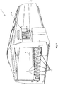
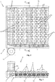
- the disk screen 1 as schematically represented in the enclosed figures comprises a support structure 2, intended to abut against the ground, and on which a plurality of rotation shafts 3 - parallel to and spaced from each other - are rotatably mounted, as in particular can be appreciated in the image of figure 2 which represents a plan view of the screen.
- the rotation shafts 3 have longitudinal extension axes, indicated with Y, which define a preferably horizontal position, as illustrated in the drawings, but which can also assume a tilt without departing from the protective scope of the present patent.
- Driving means 4 are provided that are adapted to carry the shafts 3 in rotation, in the rotation direction indicated by the arrow and marked with the reference R.
- the shafts 3 all rotate in the same rotation direction R in order to move the residues between an inlet port and an outlet port in a per se entirely conventional manner, for this reason not described in more detail.
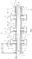
- the driving means 4 comprise an electric motor 4a and motion transmission means 5 mechanically connected to the electric motor 4a.
- Such transmission means 5 in turn comprise a chain 6 wound as a closed loop and engaging with a pinion 7 fixed to the shaft of the motor 4a and to gear wheels 70 fit on each rotation shaft 3.
- the screen 1 also comprises a plurality of disks 8, which are axially mounted in succession along the rotation shafts 3 in order to receive the rotation motion therefrom.
- each rotation shaft 3 a group of disks 8 is mounted which, for example, in accordance with the enclosed figure 2 , can be formed by nine and ten disks on adjacent shafts in succession.
- the disks 8 of each group of disks are mounted spaced from each other along the extension of the longitudinal axis Y of the rotation shaft 3.
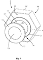
- the screen 1 is also provided with a plurality of sleeves 10, each of which comprising a tubular body 11, which is mounted externally idle on a respective rotation shaft 3 between two disks 8 in succession, and is provided with an inner surface 11A, oriented toward the rotation shaft 3, and with an outer surface 11B oriented in a opposite direction with respect to the inner surface 11A.
- the disks 8 are instead otherwise mechanically rotatably coupled to the rotation shaft 3 in order to receive the rotation motion thereof.
- the rotation shaft 3 for example has a male shaped profile 30, defined by the form of its external surface and in particular by its cross section, and the disk 8 has a female shaped profile 80 joined to the aforesaid male shaped profile 30, and in particular defined by a through hole adapted to receive the aforesaid male shaped profile 30.
- the male shaped profile 30 has a polygonal (e.g. hexagonal) cross section
- the disks 8 have a female shaped profile 80 defined by a through hole 80 with corresponding polygonal shape traversed, to size, by the rotation shaft 3 which, due to the aforesaid form engagement, is thus susceptible to rotate the group of disks 8.
- each disk 8 has the shape of a hexagonal polygonal prism having six flat faces 8C that facilitate the advancement of the residues to be screened during the rotation of the shafts 2.
- the disks 8 can also have external profiles of different shape, advantageously adapted for facilitating the advancement of the residues between the inlet port and the outlet port.
- the motor 4a - by means of the chain 6 wound as a ring on the pinion 7 of the motor shaft and on the gear wheels 70 of the rotation shafts 3 - rotates the rotation shafts 3 in the same direction, indicated with R, and the hexagonal profile with flat face 8C of the disks 8 impacts with the residues, facilitating the advancement thereof via thrust along the screening plane in the advancement direction indicated with A in figure 1 .
- the presence of the sleeves 10 prevents, or at least limits, the winding of filiform residues around the rotation shafts 3. Indeed, the sleeves 10 do not follow the rotation shafts 3 during their rotation and are not integrally moved with the residues.
- Each disk 8 is provided with two lateral faces 8A and 8B orthogonal to the longitudinal axis Y of the respective rotation shafts 3.
- Such faces 8A and 8B are preferably substantially parallel and oriented in opposite directions.
- the lateral faces 8A and 8B of the disks 8 have each a central depression 12 of circular form and each sleeve 10 in turn comprises two annular shoulders 13 which are fixed to the ends of the tubular body 11, and project radially from the outer surface 11B of the tubular body 11 itself.
- each annular shoulder 13 is provided with an external section 13' which projects from the outer surface 11B of the tubular body 11 of the corresponding sleeve 10, extending outside the tubular body 11 itself, and in particular extending substantially orthogonally to the outer surface 11B of the tubular body 11.
- Each annular shoulder 13 is inserted, preferably substantially to size, within the central depressions 12 of the corresponding lateral face 8A, 8B of the disk 8.
- each sleeve 10 is fixed to the ends of the tubular body 11 by means of fixing means, such as welding or screw means.
- the sleeves 10 with their annular shoulders 13 remain mainly stopped, given that they are idly mounted on the rotation shafts 3.
- the provided object of the invention - to insert the annular shoulders 13 within the central depressions 12 - allows obtaining the necessary clearance between the two moving parts at a position in which it is improbable that there will be an insertion of undesired material that would lead to connecting the sleeve 10 to the disk 8 and to the shaft 3, i.e. bringing in rotation also the sleeve 10, as if it were not idly mounted.
- the clearance between sleeve and disks is obtained on the tubular body, i.e. on the bottom of the space enclosed between the disks, and involves the undesired penetration of material with the consequent formation of a mechanical drive constraint between sleeves and disks that leads to the twisting of the filiform material.
- the depressions 12 are situated on a lying plane that is more retreated and within the disk 8 than the plane defined by the remaining annular portions 9 of the lateral faces 8A, 8B, to which the depressions 12 are connected by means of a sunken edge 120.
- sunken edge 120 peripherally delimits the depressions 12 and is therefore extended with an axial component within the thickness of the disk 8.
- the sunken edge 120 of the depressions 12 of each lateral face 8A, 8B of each disk 8 faces, preferably to size, the circumferential profile 113 of the corresponding annular shoulder 13 inserted in the depression 12 itself.
- the term "to size” means that the sunken edge 120 of each depression 12 faces the circumferential profile 113 of the corresponding annular shoulder 13 with a clearance (defined as the distance between the circumferential profile 113 and the sunken edge 120) of about 1-5 centimeters and preferably of about 3-4 centimeters.
- the lateral areas of the annular shoulders 13, i.e. the most external faces directed towards the opposite shoulder 13 of the same sleeve 10, are embedded within the central depressions 12, i.e. they are slightly recessed in the disk 8 by a thickness S illustrated in figure 4 .
- each sleeve 10 are radially extended for an inner section 23 towards the longitudinal axis Y of the shaft 3 and are each provided with a through hole 130 traversed by the same rotation shaft 3.
- each annular shoulder 13 projects from the inner surface 11A of the tubular body 11 of the corresponding sleeve 10, and is preferably provided with an inner edge defining the above mentioned through hole 130.
- each sleeve 10 obtained with shaped metal plates are ring shaped, centrally provided with the through hole 130 for traversing the shaft 3.
- the screen 1 also comprises preferably a plurality of spacer tubular bodies 14, each of which is externally mounted on the rotation shaft 3 and is interposed and in abutment between the lateral faces 8A and 8B of two disks 8 in succession. Therefore, the disks 8 are inserted in succession on the rotation shaft 3, alternating them with the spacer tubular bodies 14 which, being pressed between the contiguous disks, rotate together therewith.
- each spacer tubular body 14 externally with respect to each spacer tubular body 14, a corresponding sleeve 10 is externally mounted with clearance.
- each spacer tubular body 14 defines the distance between each pair of disks 8 in succession and is slightly greater than the longitudinal length d of each sleeve 10, in order to ensure the axial clearance of such sleeve between the pair of disks 8, between which it is comprised.
- each sleeve 10 can be rotatably moved in a free manner around the corresponding spacer tubular body 14 on which it is mounted.
- a radial clearance G is provided therebetween, illustrated as an example in figure 4 , and defined in particular between the inner edge of the inner section 23 of each annular shoulder 13 and the lateral external surface of the corresponding spacer tubular body 14.
- the finding thus conceived therefore attains the pre-established objects.
Landscapes
- Engineering & Computer Science (AREA)
- Mechanical Engineering (AREA)
- Combined Means For Separation Of Solids (AREA)
- Processing Of Solid Wastes (AREA)
- Centrifugal Separators (AREA)
- Cyclones (AREA)
- Processing And Handling Of Plastics And Other Materials For Molding In General (AREA)
Description
- The present invention regards a disk screen for separating solid materials, according to the preamble of the main independent claim.
- The present disk screen is intended to be employed, in a per se conventional manner, for separating solid materials of various type, such as: solid urban waste, inert fluvial material, products of the organic fractions of the separate waste collection, compost (for the refining thereof), recycled wood, biomass, inert material, demolition material, land drainage material and dump material, glass, plastic, scrap metal and still other materials.
- The disk screen according to the invention is therefore inserted in the industrial field of treating solid residues and is advantageously intended to be installed downstream of plants for crushing and grinding the same residues.
- Hereinbelow, the term "residues" refers - in an undifferentiated manner and for the sake of brevity - to any one solid material which requires being separated into its components based on size or mass.
- Known on the market are numerous different apparatuses intended to be employed for separating solid residues in multiple fields of application, as well as employing different structural and functioning principles. Among such apparatuses, there are for example the following: mesh screens, screw screens, disk screens, ballistic separators, drum screens, fluid bed separators, electrostatic separators, magnetic separators and still other apparatuses.
- The present invention regards a screen of disk type, for example described in the patent
US 4972959 . - More in detail, the disk screens usually comprise a support structure, which carries, rotatably mounted thereon, numerous equidistant shafts in succession, parallel to each other and rotating in a same rotation direction. A group of disks is axially fixed on each shaft, such disks separated from each other by a distance less than the thickness of the single disks, in order to allow interposing the disks mounted on the contiguous shafts such that each disk of any one shaft is interposed between two disks of the adjacent front and rear shafts.
- In the present field of the art, one thing that marks the characteristics of the disk screen is the screening surface. The latter is defined as the area of the openings delimited between the disks and the rotating shafts and is therefore indicative of the size of the residues that are separated by the screen, falling by gravity below the surface of the screening surface.
- A screen is known from the model
DE 29711724 in which the disks mounted on the rotating shafts are maintained spaced from each other by spacer rollers directly fit on the disks, so as to rotate together therewith. - The disk screens of the above-described type have in practice proven that they do not lack drawbacks.
- The main drawback lies in the fact that the presence of filiform elements between the residues to be screened, such as the presence of cables, strips, rags, plastic bags and similar materials, jeopardizes the correct operation of the screen. Such filiform elements in fact tend to be twisted around the disks and shafts of the screen and to obstruct the spaces between the disks, modifying the screen area and in the end compromising the screening operations.
- Consequently, repeated maintenance operations are frequently necessary for these screens, for cleaning operations, with consequent undesired stops of production.
- In order to overcome such drawbacks, a disk screen is known from the patent
EP 1106264 on behalf of the same Applicant that is provided with idle sleeves interposed between the disks, such sleeves having the function of preventing or at least limiting the obstruction of the screen area. - More in detail, each sleeve is axially mounted on the shaft between two disks with clearance adapted to allow it to freely idly rotate on the shaft or on a tubular body provided externally with respect to the shaft.
- In operation, possible filiform elements that twist externally with respect to the idle sleeves, until they affect the disks mounted on the adjacent shafts, would not compromise the functioning of the screen nor would they cause stoppage since each sleeve, being idle with respect to the shaft on which it is mounted, would be driven in rotation without constraining the rotation of the shafts.
- Also known, from the patent application
WO -A- 2011045656 on behalf of the same Applicant, is a screen of the above-described type, in accordance with the preamble ofclaim 1, in which a stabilizing mass is arranged within the idle sleeves in order to prevent or at least limit, during screen operation, the sleeves from being driven in rotation by the filiform elements, facilitating the twisting of the latter. PatentDE 102007027846 describes a further example of a disk screen of the known type, which is provided with a plurality of sleeves, each comprising a tubular body mounted idle on a corresponding rotating shaft between two disks in succession. Each lateral face of the disks has a central depression of circular form, which is intended to receive in abutment the terminal edge of the tubular body of the corresponding sleeve. - The disk screens with idle sleeves of the above-described known type have in practice the drawback of allowing small-size material (such as sand, dust etc.) to be inserted in the clearance existing between the idle sleeves and the disks fit on the shafts, so as to create a mechanical connection between the rotating shafts and the sleeves themselves, coming to drive in rotation the sleeves to the detriment of their anti-twisting action.
- In this situation, the problem underlying the present invention is therefore that of eliminating the problems of the abovementioned prior art, by providing a disk screen in accordance with
claim 1 for separating solid materials which is entirely reliable in operation over time. - Another object of the present invention is to provide a disk screen for separating solid materials which prevents repeating maintenance operations due to the twisting of filiform elements.
- Another object of the present invention is to provide a disk screen for separating solid materials which is capable of maintaining the idle rotation of provided sleeves mounted on rotation shafts.
- Another object of the present invention is to provide a disk screen for separating solid materials which is simple and inexpensive to attain and entirely reliable in operation.
- Another object of the present invention is to provide a disk screen for separating solid materials which can be employed in a versatile manner in different application areas.
- The technical characteristics of the finding, according to the aforesaid objects, can be clearly seen in the contents of the below-reported claims and the advantages thereof will be clearer in the following detailed description, made with reference to the enclosed drawings, which represent a merely exemplifying and non-limiting embodiment of the invention, in which:
-
figure 1 shows a perspective image of the disk screen for separating solid materials, according to the present invention; -
figure 2 shows an enlarged detail of the screen offigure 1 in plan view, relative to several rotation shafts with a plurality of disks mounted thereon; -
figure 3 shows the detail offigure 2 in a side view; -
figure 4 shows a section view carried out along the lines IV - IV offigure 2 ; -
figure 5 shows an enlarged detail of the screen offigure 1 relative to a disk with a sleeve associated therewith, in perspective view; -
figure 6 shows an enlarged detail of the screen offigure 1 relative to a disk with a spacer associated therewith together with a rotation shaft portion, with the sleeve offigure 5 depicted in exploded view. - With reference to the enclosed drawings,
reference number 1 indicates a disk screen for separating solid materials, subject of the present invention. - The
screen 1 according to the invention is adapted to be employed for separating solid materials of various type, such as: solid urban waste, inert fluvial material, products of the organic fractions of the separate waste collection, compost (for the refining thereof), recycled wood, biomass, inert material, demolition material, land drainage material and dump material, glass, plastic, scrap metal and still other materials. - The
disk screen 1 as schematically represented in the enclosed figures comprises asupport structure 2, intended to abut against the ground, and on which a plurality of rotation shafts 3 - parallel to and spaced from each other - are rotatably mounted, as in particular can be appreciated in the image offigure 2 which represents a plan view of the screen. - The
rotation shafts 3 have longitudinal extension axes, indicated with Y, which define a preferably horizontal position, as illustrated in the drawings, but which can also assume a tilt without departing from the protective scope of the present patent. - Driving means 4 are provided that are adapted to carry the
shafts 3 in rotation, in the rotation direction indicated by the arrow and marked with the reference R. - The
shafts 3 all rotate in the same rotation direction R in order to move the residues between an inlet port and an outlet port in a per se entirely conventional manner, for this reason not described in more detail. - In accordance with a preferred embodiment of the invention illustrated in
figures 2 and 3 , the driving means 4 comprise anelectric motor 4a and motion transmission means 5 mechanically connected to theelectric motor 4a. Such transmission means 5 in turn comprise achain 6 wound as a closed loop and engaging with apinion 7 fixed to the shaft of themotor 4a and togear wheels 70 fit on eachrotation shaft 3. - The
screen 1 also comprises a plurality ofdisks 8, which are axially mounted in succession along therotation shafts 3 in order to receive the rotation motion therefrom. - More in detail, on each
rotation shaft 3, a group ofdisks 8 is mounted which, for example, in accordance with the enclosedfigure 2 , can be formed by nine and ten disks on adjacent shafts in succession. - The
disks 8 of each group of disks are mounted spaced from each other along the extension of the longitudinal axis Y of therotation shaft 3. - The
screen 1 is also provided with a plurality ofsleeves 10, each of which comprising atubular body 11, which is mounted externally idle on arespective rotation shaft 3 between twodisks 8 in succession, and is provided with aninner surface 11A, oriented toward therotation shaft 3, and with anouter surface 11B oriented in a opposite direction with respect to theinner surface 11A. - The
disks 8 are instead otherwise mechanically rotatably coupled to therotation shaft 3 in order to receive the rotation motion thereof. - For such purpose, the
rotation shaft 3 for example has a male shapedprofile 30, defined by the form of its external surface and in particular by its cross section, and thedisk 8 has a femaleshaped profile 80 joined to the aforesaid male shapedprofile 30, and in particular defined by a through hole adapted to receive the aforesaid male shapedprofile 30. - More in detail, the male shaped
profile 30 has a polygonal (e.g. hexagonal) cross section, and thedisks 8 have a female shapedprofile 80 defined by athrough hole 80 with corresponding polygonal shape traversed, to size, by therotation shaft 3 which, due to the aforesaid form engagement, is thus susceptible to rotate the group ofdisks 8. - Preferably, each
disk 8 has the shape of a hexagonal polygonal prism having sixflat faces 8C that facilitate the advancement of the residues to be screened during the rotation of theshafts 2. In other embodiments of the present invention, thedisks 8 can also have external profiles of different shape, advantageously adapted for facilitating the advancement of the residues between the inlet port and the outlet port. - Functionally, when the
screen 1 is operating, themotor 4a - by means of thechain 6 wound as a ring on thepinion 7 of the motor shaft and on thegear wheels 70 of the rotation shafts 3 - rotates therotation shafts 3 in the same direction, indicated with R, and the hexagonal profile withflat face 8C of thedisks 8 impacts with the residues, facilitating the advancement thereof via thrust along the screening plane in the advancement direction indicated with A infigure 1 . - During such advancement of the residues, those with size smaller than the openings defined between the
disks 8 and thesleeves 10 fall via gravity below the screening plane, obtaining the selection of the materials as a function of their size. - During screening, the presence of the
sleeves 10 prevents, or at least limits, the winding of filiform residues around therotation shafts 3. Indeed, thesleeves 10 do not follow therotation shafts 3 during their rotation and are not integrally moved with the residues. - Each
disk 8 is provided with twolateral faces respective rotation shafts 3. -
Such faces lateral faces disks 8 have each acentral depression 12 of circular form and eachsleeve 10 in turn comprises twoannular shoulders 13 which are fixed to the ends of thetubular body 11, and project radially from theouter surface 11B of thetubular body 11 itself. - In particular, each
annular shoulder 13 is provided with an external section 13' which projects from theouter surface 11B of thetubular body 11 of thecorresponding sleeve 10, extending outside thetubular body 11 itself, and in particular extending substantially orthogonally to theouter surface 11B of thetubular body 11. - Each
annular shoulder 13 is inserted, preferably substantially to size, within thecentral depressions 12 of the correspondinglateral face disk 8. - Advantageously, the
annular shoulders 13 of eachsleeve 10 are fixed to the ends of thetubular body 11 by means of fixing means, such as welding or screw means. - While the
disks 8 rotate, moved by therotation shaft 3, thesleeves 10 with theirannular shoulders 13 remain mainly stopped, given that they are idly mounted on therotation shafts 3. The provided object of the invention - to insert theannular shoulders 13 within the central depressions 12 - allows obtaining the necessary clearance between the two moving parts at a position in which it is improbable that there will be an insertion of undesired material that would lead to connecting thesleeve 10 to thedisk 8 and to theshaft 3, i.e. bringing in rotation also thesleeve 10, as if it were not idly mounted. - Otherwise, in the screens of the known type, the clearance between sleeve and disks is obtained on the tubular body, i.e. on the bottom of the space enclosed between the disks, and involves the undesired penetration of material with the consequent formation of a mechanical drive constraint between sleeves and disks that leads to the twisting of the filiform material. As can be observed in the enclosed
figures 4 ,5 and6 , thedepressions 12 are situated on a lying plane that is more retreated and within thedisk 8 than the plane defined by the remainingannular portions 9 of the lateral faces 8A, 8B, to which thedepressions 12 are connected by means of asunken edge 120. Suchsunken edge 120 peripherally delimits thedepressions 12 and is therefore extended with an axial component within the thickness of thedisk 8. - Advantageously, the
sunken edge 120 of thedepressions 12 of eachlateral face disk 8 faces, preferably to size, thecircumferential profile 113 of the correspondingannular shoulder 13 inserted in thedepression 12 itself. - In particular, the term "to size" means that the
sunken edge 120 of eachdepression 12 faces thecircumferential profile 113 of the correspondingannular shoulder 13 with a clearance (defined as the distance between thecircumferential profile 113 and the sunken edge 120) of about 1-5 centimeters and preferably of about 3-4 centimeters. - Consequently, the lateral areas of the
annular shoulders 13, i.e. the most external faces directed towards theopposite shoulder 13 of thesame sleeve 10, are embedded within thecentral depressions 12, i.e. they are slightly recessed in thedisk 8 by a thickness S illustrated infigure 4 . - In addition, advantageously, the
annular shoulders 13 of eachsleeve 10 are radially extended for aninner section 23 towards the longitudinal axis Y of theshaft 3 and are each provided with a throughhole 130 traversed by thesame rotation shaft 3. - In particular, the
inner section 23 of eachannular shoulder 13 projects from theinner surface 11A of thetubular body 11 of thecorresponding sleeve 10, and is preferably provided with an inner edge defining the above mentioned throughhole 130. - In accordance with a preferred embodiment of the present invention, the
annular shoulders 13 of eachsleeve 10 obtained with shaped metal plates, are ring shaped, centrally provided with the throughhole 130 for traversing theshaft 3. - The
screen 1 also comprises preferably a plurality of spacertubular bodies 14, each of which is externally mounted on therotation shaft 3 and is interposed and in abutment between the lateral faces 8A and 8B of twodisks 8 in succession. Therefore, thedisks 8 are inserted in succession on therotation shaft 3, alternating them with the spacertubular bodies 14 which, being pressed between the contiguous disks, rotate together therewith. - In addition, externally with respect to each spacer
tubular body 14, acorresponding sleeve 10 is externally mounted with clearance. - Therefore, the longitudinal length D of each spacer
tubular body 14 defines the distance between each pair ofdisks 8 in succession and is slightly greater than the longitudinal length d of eachsleeve 10, in order to ensure the axial clearance of such sleeve between the pair ofdisks 8, between which it is comprised. - In such a manner, each
sleeve 10 can be rotatably moved in a free manner around the corresponding spacertubular body 14 on which it is mounted. - In order to allow an entirely idle rotation of the
sleeves 10 on the spacertubular bodies 14, a radial clearance G is provided therebetween, illustrated as an example infigure 4 , and defined in particular between the inner edge of theinner section 23 of eachannular shoulder 13 and the lateral external surface of the corresponding spacertubular body 14. - The finding thus conceived therefore attains the pre-established objects.
Claims (8)
- Disk screen for separating solid residues, which comprises:- a support structure (2);- a plurality of rotation shafts (3) parallel to each other and rotatably mounted on said support structure (2);- means (4) for driving said rotation shafts (3) in order to rotate them around their longitudinal extension axis (Y);- a plurality of disks (8) axially mounted in succession, spaced from each other along said rotation shafts (3), provided with two lateral faces (8A, 8B) orthogonal to the longitudinal extension axis (Y) of the corresponding said rotation shafts (3);- a plurality of sleeves (10), each comprising a tubular body (11), which tubular body (11) is mounted externally idle on a corresponding said rotation shaft (3) between two disks (8) in succession, and is provided with an inner surface (11A), oriented toward said rotation shaft (3), and with an outer surface (11B) oriented in a opposite direction with respect to said inner surface (11A); wherein, said disks (8) are instead otherwise mechanically rotatably coupled to said rotation shaft (3) in order to receive the rotation motion thereof;the lateral faces (8A, 8B) of said disks (8) having a central depression (12) of circular form;
said disk screen being characterized in that each said sleeve (10) comprises two annular shoulders (13), which are fixed to the ends of said tubular body (11), radially project from the outer surface (11B) of said tubular body (11) and are inserted inside the central depressions (12) of the lateral faces (8A, 8B) of said disks (8);
wherein the annular shoulders (13) of each said sleeve (10) are obtained with shaped metal plates. - Disk screen for separating solid residues according to claim 1, characterized in that said depressions (12) are perimetrically delimited by a sunken edge (120) facing, to size, the circumferential profile (113) of said annular shoulders (13).
- Disk screen for separating solid residues according to claim 1, characterized in that the lateral areas of said annular shoulders (13) are embedded within said central depressions (12).
- Disk screen for separating solid residues according to claim 1, characterized in that the annular shoulders (13) of each said sleeve (10) are radially extended towards the axis (Y) of said rotation shaft (3) and are each provided with a through hole (130) traversed by said rotation shaft (3) in order to allow the idle rotation of said sleeve (10) on said rotation shaft (3).
- Disk screen for separating solid residues according to claim 1, characterized in that the annular shoulders (13) of each said sleeve (10) are fixed to the ends of said tubular body (11) by means of fixing means.
- Disk screen for separating solid residues according to claim 1, characterized in that it comprises a plurality of spacer tubular bodies (14), each of which is externally mounted on a corresponding said rotation shaft (3), is interposed and in abutment between the lateral faces (8A, 8B) of two disks (8) in succession, and externally carries a corresponding said sleeve (10) idly mounted thereon.
- Disk screen for separating solid residues according to claim 6, characterized in that the longitudinal length (D) of said spacer tubular bodies (14) is greater than the longitudinal length (d) of said sleeves (10).
- Disk screen for separating solid residues according to claim 6, characterized in that between said spacer tubular bodies (14) and said sleeves (10), a radial clearance (G) is present.
Priority Applications (4)
| Application Number | Priority Date | Filing Date | Title |
|---|---|---|---|
| SI201630703T SI3085462T1 (en) | 2015-04-23 | 2016-04-22 | Disk screen for separating solid materials |
| PL16166548T PL3085462T3 (en) | 2015-04-23 | 2016-04-22 | Disk screen for separating solid materials |
| RS20200363A RS60086B1 (en) | 2015-04-23 | 2016-04-22 | Disk screen for separating solid materials |
| HRP20200531TT HRP20200531T1 (en) | 2015-04-23 | 2020-04-01 | Disk screen for separating solid materials |
Applications Claiming Priority (1)
| Application Number | Priority Date | Filing Date | Title |
|---|---|---|---|
| ITPD2015A000086A ITPD20150086A1 (en) | 2015-04-23 | 2015-04-23 | DISC SCREEN FOR THE SEPARATION OF SOLID MATERIALS |
Publications (2)
| Publication Number | Publication Date |
|---|---|
| EP3085462A1 EP3085462A1 (en) | 2016-10-26 |
| EP3085462B1 true EP3085462B1 (en) | 2020-01-01 |
Family
ID=53765332
Family Applications (1)
| Application Number | Title | Priority Date | Filing Date |
|---|---|---|---|
| EP16166548.4A Active EP3085462B1 (en) | 2015-04-23 | 2016-04-22 | Disk screen for separating solid materials |
Country Status (11)
| Country | Link |
|---|---|
| EP (1) | EP3085462B1 (en) |
| CA (1) | CA2894043A1 (en) |
| DK (1) | DK3085462T3 (en) |
| ES (1) | ES2781702T3 (en) |
| HR (1) | HRP20200531T1 (en) |
| IT (1) | ITPD20150086A1 (en) |
| LT (1) | LT3085462T (en) |
| PL (1) | PL3085462T3 (en) |
| PT (1) | PT3085462T (en) |
| RS (1) | RS60086B1 (en) |
| SI (1) | SI3085462T1 (en) |
Families Citing this family (7)
| Publication number | Priority date | Publication date | Assignee | Title |
|---|---|---|---|---|
| CN107457174A (en) * | 2017-10-10 | 2017-12-12 | 天津百利阳光环保设备有限公司 | A kind of disc screen for sieving house refuse |
| IT201800004449A1 (en) * | 2018-04-12 | 2019-10-12 | DISCS OR STARS SEPARATOR SCREEN FOR WASTE, AXIS THAT CAN BE USED IN THIS SCREEN AND SLEEVE THAT CAN BE USED IN THIS AXIS | |
| IT201800004450A1 (en) * | 2018-04-12 | 2019-10-12 | DISCS OR STARS SEPARATOR SCREEN FOR WASTE, AXIS THAT CAN BE USED IN THIS SCREEN AND SLEEVE THAT CAN BE USED IN THIS AXIS | |
| US11305314B2 (en) | 2018-04-12 | 2022-04-19 | GEO S.A.S. di Tazzoli Antonio & C. | Separator screen in discs or stars for waste, axle usable in such screen as well as method for modifying a separator screen in discs or stars for waste |
| IT201900013791A1 (en) | 2019-08-02 | 2021-02-02 | Ecostargreen S R L | DISC SCREEN FOR THE SEPARATION OF SOLID MATERIALS |
| CN110813694B (en) * | 2019-11-22 | 2025-01-03 | 南通中选智科环境科技有限公司 | Disc sieve |
| CN119771749B (en) * | 2025-03-11 | 2025-07-04 | 碎得机械(常州)有限公司 | Screen disc and disc screen |
Citations (5)
| Publication number | Priority date | Publication date | Assignee | Title |
|---|---|---|---|---|
| EP1106264A2 (en) * | 1999-12-01 | 2001-06-13 | ECOSTAR S.r.l. | Screen for sorting solid waste |
| DE10100473B4 (en) * | 1999-10-28 | 2008-01-24 | Eurec Technology Gmbh Development & Design | Star or disk screen assembly comprising a plurality of screen disk shafts |
| DE102007027846B3 (en) | 2007-06-13 | 2008-05-15 | Neuenhauser Maschinenbau Gmbh | Star-shaped screening machine for screening e.g. peat, of domestic waste, has screening disks with pockets, and sleeve extending in pockets, where two disks are enclosed by freely rotatable sleeve, which is made of impact-resistant plastic |
| DE10117496B4 (en) * | 1999-10-28 | 2009-02-19 | Eurec Technology Gmbh Development & Design | Star or disk screen assembly comprising a plurality of screen disk shafts |
| WO2011045656A1 (en) | 2009-10-14 | 2011-04-21 | Ecostar S.R.L. | Screeb for separating solid materials |
Family Cites Families (4)
| Publication number | Priority date | Publication date | Assignee | Title |
|---|---|---|---|---|
| GB833698A (en) * | 1956-01-13 | 1960-04-27 | August Fischer | Improvements in or relating to idler rollers for endless belt conveyor assemblies |
| US4972959A (en) | 1989-11-30 | 1990-11-27 | Beloit Corporation | Compressible ring spacer disk screen |
| DE29711724U1 (en) | 1997-07-04 | 1997-09-04 | Kronenberger, Ernst Josef, 66706 Perl | Scraper for a disc sieve or a disc separator |
| US6250478B1 (en) * | 1999-02-08 | 2001-06-26 | C P Manufacturing Inc. | Stepped disc screens of unequal inclination angles for conveying and grading recycling materials |
-
2015
- 2015-04-23 IT ITPD2015A000086A patent/ITPD20150086A1/en unknown
- 2015-06-09 CA CA2894043A patent/CA2894043A1/en not_active Abandoned
-
2016
- 2016-04-22 PL PL16166548T patent/PL3085462T3/en unknown
- 2016-04-22 RS RS20200363A patent/RS60086B1/en unknown
- 2016-04-22 DK DK16166548.4T patent/DK3085462T3/en active
- 2016-04-22 EP EP16166548.4A patent/EP3085462B1/en active Active
- 2016-04-22 LT LTEP16166548.4T patent/LT3085462T/en unknown
- 2016-04-22 SI SI201630703T patent/SI3085462T1/en unknown
- 2016-04-22 PT PT161665484T patent/PT3085462T/en unknown
- 2016-04-22 ES ES16166548T patent/ES2781702T3/en active Active
-
2020
- 2020-04-01 HR HRP20200531TT patent/HRP20200531T1/en unknown
Patent Citations (5)
| Publication number | Priority date | Publication date | Assignee | Title |
|---|---|---|---|---|
| DE10100473B4 (en) * | 1999-10-28 | 2008-01-24 | Eurec Technology Gmbh Development & Design | Star or disk screen assembly comprising a plurality of screen disk shafts |
| DE10117496B4 (en) * | 1999-10-28 | 2009-02-19 | Eurec Technology Gmbh Development & Design | Star or disk screen assembly comprising a plurality of screen disk shafts |
| EP1106264A2 (en) * | 1999-12-01 | 2001-06-13 | ECOSTAR S.r.l. | Screen for sorting solid waste |
| DE102007027846B3 (en) | 2007-06-13 | 2008-05-15 | Neuenhauser Maschinenbau Gmbh | Star-shaped screening machine for screening e.g. peat, of domestic waste, has screening disks with pockets, and sleeve extending in pockets, where two disks are enclosed by freely rotatable sleeve, which is made of impact-resistant plastic |
| WO2011045656A1 (en) | 2009-10-14 | 2011-04-21 | Ecostar S.R.L. | Screeb for separating solid materials |
Non-Patent Citations (9)
| Title |
|---|
| "Crible etoile Hammel 04", 28 February 2013 (2013-02-28), Retrieved from the Internet <URL:https://www.youtube.com/watch?v=_lid3FYwKLo>> [retrieved on 201805] * |
| "Crible etoile Hammel 05", YOUTUBE, 28 February 2013 (2013-02-28), XP054980986, Retrieved from the Internet <URL:https://www.youtube.com/watch?v=zOdNlX3GDPM> [retrieved on 20180505] |
| "Crible etoile Hammel", 28 February 2013 (2013-02-28), Retrieved from the Internet <URL:https://www.youtube.com/watch?v=zOdNlX3GDPM> [retrieved on 201805] * |
| "Pollutec", HAMMEL, 12 April 2009 (2009-04-12) |
| ANONYMOUS: "Messetermine 07.11.2011 bis 08.11.2011", HAMMEL, 25 September 2011 (2011-09-25), XP055739357, Retrieved from the Internet <URL:https://web.archive.org/web/20110925085732/http://www.hammel.de:80/news/termine.php> |
| ANONYMOUS: "Messetermine 09.04.2010 bis 11.04.2010", HAMMEL, 14 December 2009 (2009-12-14), XP055739367, Retrieved from the Internet <URL:http://www.hammel.de> |
| HAMMEL FRANCE: "crible etoile HAMMEL 01", YOUTUBE, 28 February 2013 (2013-02-28), XP054980987, Retrieved from the Internet <URL:https://www.youtube.com/watch?v=-aOyAzacB-U> |
| HAMMEL FRANCE: "Crible etoile Hammel 04", YOUTUBE, 28 February 2013 (2013-02-28), XP054980985, Retrieved from the Internet <URL:https://www.youtube.com/watch?v=_lid3FYwKLo> [retrieved on 20180505] |
| HAMMEL, 10 September 2009 (2009-09-10), Retrieved from the Internet <URL:https://web.archive.org/web/20091009215138/http://www.hammel.de/termine/termine_fr.php4> |
Also Published As
| Publication number | Publication date |
|---|---|
| ES2781702T3 (en) | 2020-09-04 |
| RS60086B1 (en) | 2020-05-29 |
| EP3085462A1 (en) | 2016-10-26 |
| LT3085462T (en) | 2020-04-10 |
| ITPD20150086A1 (en) | 2016-10-23 |
| DK3085462T3 (en) | 2020-03-30 |
| SI3085462T1 (en) | 2020-09-30 |
| HRP20200531T1 (en) | 2020-09-18 |
| CA2894043A1 (en) | 2016-10-23 |
| PL3085462T3 (en) | 2020-11-30 |
| PT3085462T (en) | 2020-03-31 |
Similar Documents
| Publication | Publication Date | Title |
|---|---|---|
| EP3085462B1 (en) | Disk screen for separating solid materials | |
| EP3771499B1 (en) | Disc screen for separating solid materials | |
| JP6338891B2 (en) | Sieve screen bucket that works with heavy machinery | |
| US11642701B2 (en) | Disc screen for separating solid materials | |
| KR101620277B1 (en) | crushing apparatus | |
| DE102012010215A1 (en) | Shredder with quickly exchangeable knife shaft | |
| US9481014B2 (en) | Sieve screen | |
| CA2748288A1 (en) | Screen star, in particular for a star screen machine | |
| CN203917105U (en) | A kind of roller screen machine and screen drum device thereof | |
| KR101375569B1 (en) | A stone processing device | |
| EP3533525B1 (en) | Waste separation device | |
| US3173493A (en) | Earth working roller unit with dieferential speed rollers | |
| CN104024532A (en) | Drum with screening and crushing unit | |
| WO2014101909A1 (en) | Ring wheel and roller for soil cultivation | |
| CN115283233A (en) | Roller type multi-stage screening auxiliary tool for skid steer loader | |
| JP6325800B2 (en) | Auger head | |
| US9938827B2 (en) | End plate interlock for housing of a ground breaking machine and method of mounting a cutter drum in the housing | |
| KR101984854B1 (en) | Segment wheel and cart having it | |
| KR101863799B1 (en) | Chain block | |
| KR102485423B1 (en) | Trommel | |
| CN105289982B (en) | A kind of drum-type cleaning plant | |
| JP2015047584A (en) | Chain and chain structure using the same | |
| CN108080098A (en) | For the disruption elements and its building method of sludge crusher | |
| DE4428012C2 (en) | Pane interior pane | |
| NZ737656B2 (en) | Filter panel with structures support grid and drum filter with said filter panel |
Legal Events
| Date | Code | Title | Description |
|---|---|---|---|
| PUAI | Public reference made under article 153(3) epc to a published international application that has entered the european phase |
Free format text: ORIGINAL CODE: 0009012 |
|
| AK | Designated contracting states |
Kind code of ref document: A1 Designated state(s): AL AT BE BG CH CY CZ DE DK EE ES FI FR GB GR HR HU IE IS IT LI LT LU LV MC MK MT NL NO PL PT RO RS SE SI SK SM TR |
|
| AX | Request for extension of the european patent |
Extension state: BA ME |
|
| 17P | Request for examination filed |
Effective date: 20170426 |
|
| RBV | Designated contracting states (corrected) |
Designated state(s): AL AT BE BG CH CY CZ DE DK EE ES FI FR GB GR HR HU IE IS IT LI LT LU LV MC MK MT NL NO PL PT RO RS SE SI SK SM TR |
|
| STAA | Information on the status of an ep patent application or granted ep patent |
Free format text: STATUS: REQUEST FOR EXAMINATION WAS MADE |
|
| TPAC | Observations filed by third parties |
Free format text: ORIGINAL CODE: EPIDOSNTIPA |
|
| STAA | Information on the status of an ep patent application or granted ep patent |
Free format text: STATUS: EXAMINATION IS IN PROGRESS |
|
| 17Q | First examination report despatched |
Effective date: 20190429 |
|
| GRAP | Despatch of communication of intention to grant a patent |
Free format text: ORIGINAL CODE: EPIDOSNIGR1 |
|
| STAA | Information on the status of an ep patent application or granted ep patent |
Free format text: STATUS: GRANT OF PATENT IS INTENDED |
|
| GRAS | Grant fee paid |
Free format text: ORIGINAL CODE: EPIDOSNIGR3 |
|
| INTG | Intention to grant announced |
Effective date: 20191111 |
|
| GRAA | (expected) grant |
Free format text: ORIGINAL CODE: 0009210 |
|
| STAA | Information on the status of an ep patent application or granted ep patent |
Free format text: STATUS: THE PATENT HAS BEEN GRANTED |
|
| AK | Designated contracting states |
Kind code of ref document: B1 Designated state(s): AL AT BE BG CH CY CZ DE DK EE ES FI FR GB GR HR HU IE IS IT LI LT LU LV MC MK MT NL NO PL PT RO RS SE SI SK SM TR |
|
| REG | Reference to a national code |
Ref country code: GB Ref legal event code: FG4D |
|
| REG | Reference to a national code |
Ref country code: DE Ref legal event code: R026 Ref document number: 602016027150 Country of ref document: DE |
|
| PLBI | Opposition filed |
Free format text: ORIGINAL CODE: 0009260 |
|
| REG | Reference to a national code |
Ref country code: CH Ref legal event code: EP Ref country code: AT Ref legal event code: REF Ref document number: 1219120 Country of ref document: AT Kind code of ref document: T Effective date: 20200115 |
|
| REG | Reference to a national code |
Ref country code: IE Ref legal event code: FG4D |
|
| REG | Reference to a national code |
Ref country code: DE Ref legal event code: R096 Ref document number: 602016027150 Country of ref document: DE |
|
| 26 | Opposition filed |
Opponent name: GEO S.A.S. DI TAZZOLI ANTONIO & C. Effective date: 20200102 |
|
| REG | Reference to a national code |
Ref country code: FI Ref legal event code: MDE Opponent name: GEO S.A.S. DI TAZZOLI ANTONIO & C. |
|
| REG | Reference to a national code |
Ref country code: RO Ref legal event code: EPE |
|
| REG | Reference to a national code |
Ref country code: DK Ref legal event code: T3 Effective date: 20200325 |
|
| REG | Reference to a national code |
Ref country code: PT Ref legal event code: SC4A Ref document number: 3085462 Country of ref document: PT Date of ref document: 20200331 Kind code of ref document: T Free format text: AVAILABILITY OF NATIONAL TRANSLATION Effective date: 20200320 |
|
| REG | Reference to a national code |
Ref country code: HR Ref legal event code: TUEP Ref document number: P20200531T Country of ref document: HR |
|
| REG | Reference to a national code |
Ref country code: FI Ref legal event code: FGE |
|
| PLAB | Opposition data, opponent's data or that of the opponent's representative modified |
Free format text: ORIGINAL CODE: 0009299OPPO |
|
| REG | Reference to a national code |
Ref country code: SE Ref legal event code: TRGR |
|
| REG | Reference to a national code |
Ref country code: NL Ref legal event code: FP |
|
| R26 | Opposition filed (corrected) |
Opponent name: GEO S.A.S. DI TAZZOLI ANTONIO & C. Effective date: 20200102 |
|
| REG | Reference to a national code |
Ref country code: HR Ref legal event code: ODRP Ref document number: P20200531T Country of ref document: HR Payment date: 20200605 Year of fee payment: 5 |
|
| REG | Reference to a national code |
Ref country code: EE Ref legal event code: FG4A Ref document number: E018930 Country of ref document: EE Effective date: 20200324 |
|
| REG | Reference to a national code |
Ref country code: SK Ref legal event code: T3 Ref document number: E 33880 Country of ref document: SK |
|
| PG25 | Lapsed in a contracting state [announced via postgrant information from national office to epo] |
Ref country code: NO Free format text: LAPSE BECAUSE OF FAILURE TO SUBMIT A TRANSLATION OF THE DESCRIPTION OR TO PAY THE FEE WITHIN THE PRESCRIBED TIME-LIMIT Effective date: 20200401 |
|
| PGFP | Annual fee paid to national office [announced via postgrant information from national office to epo] |
Ref country code: EE Payment date: 20200420 Year of fee payment: 5 Ref country code: RO Payment date: 20200409 Year of fee payment: 5 Ref country code: CH Payment date: 20200420 Year of fee payment: 5 Ref country code: LT Payment date: 20200410 Year of fee payment: 5 Ref country code: PT Payment date: 20200415 Year of fee payment: 5 |
|
| REG | Reference to a national code |
Ref country code: AT Ref legal event code: UEP Ref document number: 1219120 Country of ref document: AT Kind code of ref document: T Effective date: 20200101 |
|
| PG25 | Lapsed in a contracting state [announced via postgrant information from national office to epo] |
Ref country code: GR Free format text: LAPSE BECAUSE OF FAILURE TO SUBMIT A TRANSLATION OF THE DESCRIPTION OR TO PAY THE FEE WITHIN THE PRESCRIBED TIME-LIMIT Effective date: 20200402 Ref country code: BG Free format text: LAPSE BECAUSE OF FAILURE TO SUBMIT A TRANSLATION OF THE DESCRIPTION OR TO PAY THE FEE WITHIN THE PRESCRIBED TIME-LIMIT Effective date: 20200401 |
|
| PGFP | Annual fee paid to national office [announced via postgrant information from national office to epo] |
Ref country code: IS Payment date: 20200414 Year of fee payment: 5 Ref country code: RS Payment date: 20200414 Year of fee payment: 5 Ref country code: SK Payment date: 20200421 Year of fee payment: 5 Ref country code: LV Payment date: 20200423 Year of fee payment: 5 |
|
| REG | Reference to a national code |
Ref country code: ES Ref legal event code: FG2A Ref document number: 2781702 Country of ref document: ES Kind code of ref document: T3 Effective date: 20200904 |
|
| REG | Reference to a national code |
Ref country code: HR Ref legal event code: T1PR Ref document number: P20200531 Country of ref document: HR |
|
| PGFP | Annual fee paid to national office [announced via postgrant information from national office to epo] |
Ref country code: MK Payment date: 20200608 Year of fee payment: 5 |
|
| PG25 | Lapsed in a contracting state [announced via postgrant information from national office to epo] |
Ref country code: SM Free format text: LAPSE BECAUSE OF FAILURE TO SUBMIT A TRANSLATION OF THE DESCRIPTION OR TO PAY THE FEE WITHIN THE PRESCRIBED TIME-LIMIT Effective date: 20200101 |
|
| PLAX | Notice of opposition and request to file observation + time limit sent |
Free format text: ORIGINAL CODE: EPIDOSNOBS2 |
|
| PG25 | Lapsed in a contracting state [announced via postgrant information from national office to epo] |
Ref country code: MC Free format text: LAPSE BECAUSE OF FAILURE TO SUBMIT A TRANSLATION OF THE DESCRIPTION OR TO PAY THE FEE WITHIN THE PRESCRIBED TIME-LIMIT Effective date: 20200101 |
|
| PGFP | Annual fee paid to national office [announced via postgrant information from national office to epo] |
Ref country code: SI Payment date: 20200409 Year of fee payment: 5 |
|
| PG25 | Lapsed in a contracting state [announced via postgrant information from national office to epo] |
Ref country code: LU Free format text: LAPSE BECAUSE OF NON-PAYMENT OF DUE FEES Effective date: 20200422 |
|
| PLAF | Information modified related to communication of a notice of opposition and request to file observations + time limit |
Free format text: ORIGINAL CODE: EPIDOSCOBS2 |
|
| REG | Reference to a national code |
Ref country code: HR Ref legal event code: ODRP Ref document number: P20200531 Country of ref document: HR Payment date: 20210414 Year of fee payment: 6 |
|
| PLBB | Reply of patent proprietor to notice(s) of opposition received |
Free format text: ORIGINAL CODE: EPIDOSNOBS3 |
|
| PGFP | Annual fee paid to national office [announced via postgrant information from national office to epo] |
Ref country code: HR Payment date: 20210414 Year of fee payment: 6 Ref country code: FI Payment date: 20210421 Year of fee payment: 6 |
|
| PGFP | Annual fee paid to national office [announced via postgrant information from national office to epo] |
Ref country code: SE Payment date: 20210420 Year of fee payment: 6 Ref country code: DK Payment date: 20210422 Year of fee payment: 6 Ref country code: BE Payment date: 20210420 Year of fee payment: 6 |
|
| PGFP | Annual fee paid to national office [announced via postgrant information from national office to epo] |
Ref country code: NL Payment date: 20210420 Year of fee payment: 6 |
|
| PLBP | Opposition withdrawn |
Free format text: ORIGINAL CODE: 0009264 |
|
| PLBD | Termination of opposition procedure: decision despatched |
Free format text: ORIGINAL CODE: EPIDOSNOPC1 |
|
| REG | Reference to a national code |
Ref country code: EE Ref legal event code: MM4A Ref document number: E018930 Country of ref document: EE Effective date: 20210430 |
|
| REG | Reference to a national code |
Ref country code: DE Ref legal event code: R100 Ref document number: 602016027150 Country of ref document: DE |
|
| REG | Reference to a national code |
Ref country code: LT Ref legal event code: MM4D Effective date: 20210422 |
|
| REG | Reference to a national code |
Ref country code: SK Ref legal event code: MM4A Ref document number: E 33880 Country of ref document: SK Effective date: 20210422 |
|
| PG25 | Lapsed in a contracting state [announced via postgrant information from national office to epo] |
Ref country code: EE Free format text: LAPSE BECAUSE OF NON-PAYMENT OF DUE FEES Effective date: 20210430 Ref country code: RS Free format text: LAPSE BECAUSE OF NON-PAYMENT OF DUE FEES Effective date: 20210422 Ref country code: SK Free format text: LAPSE BECAUSE OF NON-PAYMENT OF DUE FEES Effective date: 20210422 Ref country code: LI Free format text: LAPSE BECAUSE OF NON-PAYMENT OF DUE FEES Effective date: 20210430 Ref country code: LT Free format text: LAPSE BECAUSE OF NON-PAYMENT OF DUE FEES Effective date: 20210422 Ref country code: CH Free format text: LAPSE BECAUSE OF NON-PAYMENT OF DUE FEES Effective date: 20210430 Ref country code: RO Free format text: LAPSE BECAUSE OF NON-PAYMENT OF DUE FEES Effective date: 20210422 Ref country code: PT Free format text: LAPSE BECAUSE OF NON-PAYMENT OF DUE FEES Effective date: 20211022 |
|
| PLBM | Termination of opposition procedure: date of legal effect published |
Free format text: ORIGINAL CODE: 0009276 |
|
| PG25 | Lapsed in a contracting state [announced via postgrant information from national office to epo] |
Ref country code: SI Free format text: LAPSE BECAUSE OF NON-PAYMENT OF DUE FEES Effective date: 20210423 Ref country code: LV Free format text: LAPSE BECAUSE OF NON-PAYMENT OF DUE FEES Effective date: 20210422 |
|
| REG | Reference to a national code |
Ref country code: SI Ref legal event code: KO00 Effective date: 20220128 |
|
| 27C | Opposition proceedings terminated |
Effective date: 20211122 |
|
| PG25 | Lapsed in a contracting state [announced via postgrant information from national office to epo] |
Ref country code: MT Free format text: LAPSE BECAUSE OF FAILURE TO SUBMIT A TRANSLATION OF THE DESCRIPTION OR TO PAY THE FEE WITHIN THE PRESCRIBED TIME-LIMIT Effective date: 20200101 Ref country code: CY Free format text: LAPSE BECAUSE OF FAILURE TO SUBMIT A TRANSLATION OF THE DESCRIPTION OR TO PAY THE FEE WITHIN THE PRESCRIBED TIME-LIMIT Effective date: 20200101 |
|
| REG | Reference to a national code |
Ref country code: HR Ref legal event code: PBON Ref document number: P20200531 Country of ref document: HR Effective date: 20220422 |
|
| REG | Reference to a national code |
Ref country code: DK Ref legal event code: EBP Effective date: 20220430 |
|
| REG | Reference to a national code |
Ref country code: SE Ref legal event code: EUG |
|
| REG | Reference to a national code |
Ref country code: NL Ref legal event code: MM Effective date: 20220501 |
|
| REG | Reference to a national code |
Ref country code: BE Ref legal event code: MM Effective date: 20220430 |
|
| PG25 | Lapsed in a contracting state [announced via postgrant information from national office to epo] |
Ref country code: SE Free format text: LAPSE BECAUSE OF NON-PAYMENT OF DUE FEES Effective date: 20220423 Ref country code: NL Free format text: LAPSE BECAUSE OF NON-PAYMENT OF DUE FEES Effective date: 20220501 Ref country code: FI Free format text: LAPSE BECAUSE OF NON-PAYMENT OF DUE FEES Effective date: 20220422 |
|
| PG25 | Lapsed in a contracting state [announced via postgrant information from national office to epo] |
Ref country code: HR Free format text: LAPSE BECAUSE OF NON-PAYMENT OF DUE FEES Effective date: 20220422 Ref country code: BE Free format text: LAPSE BECAUSE OF NON-PAYMENT OF DUE FEES Effective date: 20220430 |
|
| PG25 | Lapsed in a contracting state [announced via postgrant information from national office to epo] |
Ref country code: DK Free format text: LAPSE BECAUSE OF NON-PAYMENT OF DUE FEES Effective date: 20220430 |
|
| P01 | Opt-out of the competence of the unified patent court (upc) registered |
Effective date: 20230323 |
|
| PG25 | Lapsed in a contracting state [announced via postgrant information from national office to epo] |
Ref country code: AL Free format text: LAPSE BECAUSE OF NON-PAYMENT OF DUE FEES Effective date: 20210422 |
|
| PGFP | Annual fee paid to national office [announced via postgrant information from national office to epo] |
Ref country code: DE Payment date: 20250422 Year of fee payment: 10 |
|
| PGFP | Annual fee paid to national office [announced via postgrant information from national office to epo] |
Ref country code: GB Payment date: 20250423 Year of fee payment: 10 Ref country code: ES Payment date: 20250529 Year of fee payment: 10 |
|
| PGFP | Annual fee paid to national office [announced via postgrant information from national office to epo] |
Ref country code: IT Payment date: 20250328 Year of fee payment: 10 |
|
| PGFP | Annual fee paid to national office [announced via postgrant information from national office to epo] |
Ref country code: FR Payment date: 20250425 Year of fee payment: 10 |
|
| PGFP | Annual fee paid to national office [announced via postgrant information from national office to epo] |
Ref country code: AT Payment date: 20250423 Year of fee payment: 10 |
|
| PGFP | Annual fee paid to national office [announced via postgrant information from national office to epo] |
Ref country code: TR Payment date: 20250415 Year of fee payment: 10 |
|
| PGFP | Annual fee paid to national office [announced via postgrant information from national office to epo] |
Ref country code: CZ Payment date: 20250414 Year of fee payment: 10 |
|
| PGFP | Annual fee paid to national office [announced via postgrant information from national office to epo] |
Ref country code: IE Payment date: 20250422 Year of fee payment: 10 |
|
| PG25 | Lapsed in a contracting state [announced via postgrant information from national office to epo] |
Ref country code: IS Free format text: LAPSE BECAUSE OF NON-PAYMENT OF DUE FEES Effective date: 20211103 |
|
| PGFP | Annual fee paid to national office [announced via postgrant information from national office to epo] |
Ref country code: PL Payment date: 20260326 Year of fee payment: 11 |