EP3084907B1 - Dispositif à impédance variable pour une turbine éolienne - Google Patents
Dispositif à impédance variable pour une turbine éolienne Download PDFInfo
- Publication number
- EP3084907B1 EP3084907B1 EP14856785.2A EP14856785A EP3084907B1 EP 3084907 B1 EP3084907 B1 EP 3084907B1 EP 14856785 A EP14856785 A EP 14856785A EP 3084907 B1 EP3084907 B1 EP 3084907B1
- Authority
- EP
- European Patent Office
- Prior art keywords
- current
- wind turbine
- variable impedance
- impedance
- variable
- Prior art date
- Legal status (The legal status is an assumption and is not a legal conclusion. Google has not performed a legal analysis and makes no representation as to the accuracy of the status listed.)
- Active
Links
- 230000001052 transient effect Effects 0.000 claims description 34
- 230000004044 response Effects 0.000 claims description 20
- 238000000034 method Methods 0.000 claims description 13
- 238000001514 detection method Methods 0.000 claims description 6
- 230000001939 inductive effect Effects 0.000 claims description 6
- 230000007935 neutral effect Effects 0.000 claims description 4
- 238000004804 winding Methods 0.000 description 40
- 230000008859 change Effects 0.000 description 37
- 239000000463 material Substances 0.000 description 5
- 239000000243 solution Substances 0.000 description 5
- 238000013016 damping Methods 0.000 description 4
- 230000000694 effects Effects 0.000 description 4
- 238000005516 engineering process Methods 0.000 description 4
- 230000004907 flux Effects 0.000 description 4
- 230000001965 increasing effect Effects 0.000 description 4
- 230000000116 mitigating effect Effects 0.000 description 4
- NJPPVKZQTLUDBO-UHFFFAOYSA-N novaluron Chemical compound C1=C(Cl)C(OC(F)(F)C(OC(F)(F)F)F)=CC=C1NC(=O)NC(=O)C1=C(F)C=CC=C1F NJPPVKZQTLUDBO-UHFFFAOYSA-N 0.000 description 4
- 230000008901 benefit Effects 0.000 description 3
- 238000006243 chemical reaction Methods 0.000 description 3
- 239000004020 conductor Substances 0.000 description 3
- 230000001276 controlling effect Effects 0.000 description 3
- 238000010586 diagram Methods 0.000 description 3
- 230000006870 function Effects 0.000 description 3
- 229920006395 saturated elastomer Polymers 0.000 description 3
- 239000002887 superconductor Substances 0.000 description 3
- 230000001133 acceleration Effects 0.000 description 2
- 230000004913 activation Effects 0.000 description 2
- 238000010276 construction Methods 0.000 description 2
- 238000011161 development Methods 0.000 description 2
- 230000018109 developmental process Effects 0.000 description 2
- 238000002347 injection Methods 0.000 description 2
- 239000007924 injection Substances 0.000 description 2
- 238000009434 installation Methods 0.000 description 2
- 238000010248 power generation Methods 0.000 description 2
- 230000009467 reduction Effects 0.000 description 2
- 238000004513 sizing Methods 0.000 description 2
- 230000003068 static effect Effects 0.000 description 2
- 230000002411 adverse Effects 0.000 description 1
- 238000013459 approach Methods 0.000 description 1
- 230000009286 beneficial effect Effects 0.000 description 1
- 230000002457 bidirectional effect Effects 0.000 description 1
- 230000005540 biological transmission Effects 0.000 description 1
- 239000003990 capacitor Substances 0.000 description 1
- 230000008878 coupling Effects 0.000 description 1
- 238000010168 coupling process Methods 0.000 description 1
- 238000005859 coupling reaction Methods 0.000 description 1
- 230000007423 decrease Effects 0.000 description 1
- 230000005611 electricity Effects 0.000 description 1
- 238000004146 energy storage Methods 0.000 description 1
- 230000017525 heat dissipation Effects 0.000 description 1
- 230000006698 induction Effects 0.000 description 1
- 238000003780 insertion Methods 0.000 description 1
- 230000037431 insertion Effects 0.000 description 1
- 230000003993 interaction Effects 0.000 description 1
- 238000005259 measurement Methods 0.000 description 1
- 238000012986 modification Methods 0.000 description 1
- 230000004048 modification Effects 0.000 description 1
- 230000035699 permeability Effects 0.000 description 1
- 238000012545 processing Methods 0.000 description 1
- 230000001105 regulatory effect Effects 0.000 description 1
- 238000012360 testing method Methods 0.000 description 1
- 230000001960 triggered effect Effects 0.000 description 1
- 238000010200 validation analysis Methods 0.000 description 1
Images


Classifications
-
- F—MECHANICAL ENGINEERING; LIGHTING; HEATING; WEAPONS; BLASTING
- F03—MACHINES OR ENGINES FOR LIQUIDS; WIND, SPRING, OR WEIGHT MOTORS; PRODUCING MECHANICAL POWER OR A REACTIVE PROPULSIVE THRUST, NOT OTHERWISE PROVIDED FOR
- F03D—WIND MOTORS
- F03D9/00—Adaptations of wind motors for special use; Combinations of wind motors with apparatus driven thereby; Wind motors specially adapted for installation in particular locations
- F03D9/20—Wind motors characterised by the driven apparatus
- F03D9/25—Wind motors characterised by the driven apparatus the apparatus being an electrical generator
- F03D9/255—Wind motors characterised by the driven apparatus the apparatus being an electrical generator connected to electrical distribution networks; Arrangements therefor
-
- G—PHYSICS
- G05—CONTROLLING; REGULATING
- G05F—SYSTEMS FOR REGULATING ELECTRIC OR MAGNETIC VARIABLES
- G05F5/00—Systems for regulating electric variables by detecting deviations in the electric input to the system and thereby controlling a device within the system to obtain a regulated output
-
- H—ELECTRICITY
- H02—GENERATION; CONVERSION OR DISTRIBUTION OF ELECTRIC POWER
- H02H—EMERGENCY PROTECTIVE CIRCUIT ARRANGEMENTS
- H02H7/00—Emergency protective circuit arrangements specially adapted for specific types of electric machines or apparatus or for sectionalised protection of cable or line systems, and effecting automatic switching in the event of an undesired change from normal working conditions
- H02H7/06—Emergency protective circuit arrangements specially adapted for specific types of electric machines or apparatus or for sectionalised protection of cable or line systems, and effecting automatic switching in the event of an undesired change from normal working conditions for dynamo-electric generators; for synchronous capacitors
-
- H—ELECTRICITY
- H02—GENERATION; CONVERSION OR DISTRIBUTION OF ELECTRIC POWER
- H02J—CIRCUIT ARRANGEMENTS OR SYSTEMS FOR SUPPLYING OR DISTRIBUTING ELECTRIC POWER; SYSTEMS FOR STORING ELECTRIC ENERGY
- H02J3/00—Circuit arrangements for ac mains or ac distribution networks
- H02J3/18—Arrangements for adjusting, eliminating or compensating reactive power in networks
- H02J3/1807—Arrangements for adjusting, eliminating or compensating reactive power in networks using series compensators
-
- H—ELECTRICITY
- H02—GENERATION; CONVERSION OR DISTRIBUTION OF ELECTRIC POWER
- H02J—CIRCUIT ARRANGEMENTS OR SYSTEMS FOR SUPPLYING OR DISTRIBUTING ELECTRIC POWER; SYSTEMS FOR STORING ELECTRIC ENERGY
- H02J3/00—Circuit arrangements for ac mains or ac distribution networks
- H02J3/18—Arrangements for adjusting, eliminating or compensating reactive power in networks
- H02J3/1821—Arrangements for adjusting, eliminating or compensating reactive power in networks using shunt compensators
- H02J3/1835—Arrangements for adjusting, eliminating or compensating reactive power in networks using shunt compensators with stepless control
-
- H—ELECTRICITY
- H02—GENERATION; CONVERSION OR DISTRIBUTION OF ELECTRIC POWER
- H02J—CIRCUIT ARRANGEMENTS OR SYSTEMS FOR SUPPLYING OR DISTRIBUTING ELECTRIC POWER; SYSTEMS FOR STORING ELECTRIC ENERGY
- H02J3/00—Circuit arrangements for ac mains or ac distribution networks
- H02J3/38—Arrangements for parallely feeding a single network by two or more generators, converters or transformers
- H02J3/381—Dispersed generators
-
- H—ELECTRICITY
- H02—GENERATION; CONVERSION OR DISTRIBUTION OF ELECTRIC POWER
- H02J—CIRCUIT ARRANGEMENTS OR SYSTEMS FOR SUPPLYING OR DISTRIBUTING ELECTRIC POWER; SYSTEMS FOR STORING ELECTRIC ENERGY
- H02J3/00—Circuit arrangements for ac mains or ac distribution networks
- H02J3/38—Arrangements for parallely feeding a single network by two or more generators, converters or transformers
- H02J3/46—Controlling of the sharing of output between the generators, converters, or transformers
- H02J3/50—Controlling the sharing of the out-of-phase component
-
- H—ELECTRICITY
- H02—GENERATION; CONVERSION OR DISTRIBUTION OF ELECTRIC POWER
- H02P—CONTROL OR REGULATION OF ELECTRIC MOTORS, ELECTRIC GENERATORS OR DYNAMO-ELECTRIC CONVERTERS; CONTROLLING TRANSFORMERS, REACTORS OR CHOKE COILS
- H02P9/00—Arrangements for controlling electric generators for the purpose of obtaining a desired output
- H02P9/007—Control circuits for doubly fed generators
-
- H—ELECTRICITY
- H02—GENERATION; CONVERSION OR DISTRIBUTION OF ELECTRIC POWER
- H02P—CONTROL OR REGULATION OF ELECTRIC MOTORS, ELECTRIC GENERATORS OR DYNAMO-ELECTRIC CONVERTERS; CONTROLLING TRANSFORMERS, REACTORS OR CHOKE COILS
- H02P9/00—Arrangements for controlling electric generators for the purpose of obtaining a desired output
- H02P9/10—Control effected upon generator excitation circuit to reduce harmful effects of overloads or transients, e.g. sudden application of load, sudden removal of load, sudden change of load
- H02P9/102—Control effected upon generator excitation circuit to reduce harmful effects of overloads or transients, e.g. sudden application of load, sudden removal of load, sudden change of load for limiting effects of transients
-
- H—ELECTRICITY
- H02—GENERATION; CONVERSION OR DISTRIBUTION OF ELECTRIC POWER
- H02P—CONTROL OR REGULATION OF ELECTRIC MOTORS, ELECTRIC GENERATORS OR DYNAMO-ELECTRIC CONVERTERS; CONTROLLING TRANSFORMERS, REACTORS OR CHOKE COILS
- H02P9/00—Arrangements for controlling electric generators for the purpose of obtaining a desired output
- H02P9/14—Arrangements for controlling electric generators for the purpose of obtaining a desired output by variation of field
- H02P9/16—Arrangements for controlling electric generators for the purpose of obtaining a desired output by variation of field due to variation of ohmic resistance in field circuit, using resistances switched in or out of circuit step by step
-
- H—ELECTRICITY
- H02—GENERATION; CONVERSION OR DISTRIBUTION OF ELECTRIC POWER
- H02J—CIRCUIT ARRANGEMENTS OR SYSTEMS FOR SUPPLYING OR DISTRIBUTING ELECTRIC POWER; SYSTEMS FOR STORING ELECTRIC ENERGY
- H02J2300/00—Systems for supplying or distributing electric power characterised by decentralized, dispersed, or local generation
- H02J2300/20—The dispersed energy generation being of renewable origin
- H02J2300/28—The renewable source being wind energy
-
- Y—GENERAL TAGGING OF NEW TECHNOLOGICAL DEVELOPMENTS; GENERAL TAGGING OF CROSS-SECTIONAL TECHNOLOGIES SPANNING OVER SEVERAL SECTIONS OF THE IPC; TECHNICAL SUBJECTS COVERED BY FORMER USPC CROSS-REFERENCE ART COLLECTIONS [XRACs] AND DIGESTS
- Y02—TECHNOLOGIES OR APPLICATIONS FOR MITIGATION OR ADAPTATION AGAINST CLIMATE CHANGE
- Y02E—REDUCTION OF GREENHOUSE GAS [GHG] EMISSIONS, RELATED TO ENERGY GENERATION, TRANSMISSION OR DISTRIBUTION
- Y02E10/00—Energy generation through renewable energy sources
- Y02E10/70—Wind energy
- Y02E10/72—Wind turbines with rotation axis in wind direction
-
- Y—GENERAL TAGGING OF NEW TECHNOLOGICAL DEVELOPMENTS; GENERAL TAGGING OF CROSS-SECTIONAL TECHNOLOGIES SPANNING OVER SEVERAL SECTIONS OF THE IPC; TECHNICAL SUBJECTS COVERED BY FORMER USPC CROSS-REFERENCE ART COLLECTIONS [XRACs] AND DIGESTS
- Y02—TECHNOLOGIES OR APPLICATIONS FOR MITIGATION OR ADAPTATION AGAINST CLIMATE CHANGE
- Y02E—REDUCTION OF GREENHOUSE GAS [GHG] EMISSIONS, RELATED TO ENERGY GENERATION, TRANSMISSION OR DISTRIBUTION
- Y02E10/00—Energy generation through renewable energy sources
- Y02E10/70—Wind energy
- Y02E10/76—Power conversion electric or electronic aspects
-
- Y—GENERAL TAGGING OF NEW TECHNOLOGICAL DEVELOPMENTS; GENERAL TAGGING OF CROSS-SECTIONAL TECHNOLOGIES SPANNING OVER SEVERAL SECTIONS OF THE IPC; TECHNICAL SUBJECTS COVERED BY FORMER USPC CROSS-REFERENCE ART COLLECTIONS [XRACs] AND DIGESTS
- Y02—TECHNOLOGIES OR APPLICATIONS FOR MITIGATION OR ADAPTATION AGAINST CLIMATE CHANGE
- Y02E—REDUCTION OF GREENHOUSE GAS [GHG] EMISSIONS, RELATED TO ENERGY GENERATION, TRANSMISSION OR DISTRIBUTION
- Y02E40/00—Technologies for an efficient electrical power generation, transmission or distribution
- Y02E40/30—Reactive power compensation
Definitions
- Apparatuses and methods consistent with exemplary embodiments relate to the use of variable impedance devices, and variable impedance networks in wind turbine systems, to mitigate the effects caused by power grid disturbances such as voltage dips. Certain embodiments are configured to facilitate compliance with grid codes that are imposed upon such systems.
- FCL devices have recently been developed that can mitigate the increasing fault current levels during transmission and distribution in electrical power networks. Some of these developments have been accompanied by recent advances in superconductor technologies, which have resulted in, for example, super conductor fault limiter devices (SFCL) being developed.
- FCL devices may be divided into two main types: “permanent impedance increase” type and “condition-based impedance increase” type, which may also be referred to as “permanent impedance change” and "condition-based impedance change,” respectively.
- the former presents the same mode of operation in both normal and fault conditions, whereas the latter experiences a fast change of impedance during a fault.
- FCL devices include current limiting reactors, typically air cored, high impedance transformers, which may increase the voltage level, and any other topological measures that may lower the stiffness of the system by reducing the degree of meshing, such as splitting the system into sub-grids or any kind of bus-bar splitting.
- the stiffness of the system is high or stiff when the source impedance is low and the available fault current is high.
- any topological measure which increases impedance and lowers a fault current may lower the system stiffness.
- the reduction of source terminal voltage is much less than it would be on a 'soft' system during a short circuit condition.
- Condition-based impedance change FCL devices may be either passive or active, and may be connected in series or in a shunt arrangement.
- An example of a passive type, condition-based impedance change device is a current limiting fuse. These develop an arcing voltage high enough to effectively limit the current.
- Two types of current limiting fuses that may be used include stand-alone high voltage (HV) fuses and commutation fuse-based limiters.
- Both “permanent impedance change” FCL and “condition-based impedance change” FCL devices could be of the “passive” or “active” type.
- the impedance change can happen naturally, as the device is stressed by the presence of fault currents, without being controlled by another device or circuit, and may therefore be called an uncontrolled, non-controlled, or passive device.
- the impedance change can be triggered by control circuitry, and may be called a controlled or active device.
- FCL devices may be connected in series with the power flow, although they are sometimes connected in a shunt fashion, diverting some of the fault currents to, for instance, the system ground. When connected in series, they may exhibit low impedance that increases rapidly during a fault event. Conversely, when connected in a shunt fashion they experience high impedance that reduces rapidly during a fault condition.
- the temperature threshold for superconducting operation is very low, in the vicinity of 4° K, or in the region of 70° K, in the case of High Temperature Superconductivity (HTS). For that reason, superconducting materials are stored in cryogenic chambers. Not all passive FCL technologies require the use of superconducting technologies.
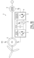
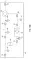
- Wind turbines based on the doubly fed induction generator (DFIG), such as doubly fed machine (DFM) shown in figure 1A or exciter based doubly fed machine (xDFM) shown in figure 1B may be very sensitive to grid disturbances and especially sensitive to voltage dips. Overvoltages and overcurrents may occur in the rotor windings in response to abrupt drops in grid voltage that can damage the power converter if no protection is provided.
- a way to mitigate this transient while protecting the converter includes connecting a so-called crowbar circuit in a shunt fashion, also known as a shunt arrangement, between the rotor terminals and the converter.
- FIG. 1A shows a wind turbine generator 10 with a conventional active crowbar circuit 20 coupled to a back-to-back type converter 30 and a DFIG 40.
- the back-to-back (B2B) converter 30 includes a rotor-side or machine-side converter (MSC) 31 and a grid-side converter (GSC) 32, also known as a front-end converter or line-side converter, that are linked through a DC link or DC bus.
- MSC machine-side converter
- GSC grid-side converter
- Three phases of the rotor of the DFIG can be connected to the crowbar circuit 20 and the MSC 31, as shown in Fig. 1A.
- Three phases of the stator of the DFIG 40 are connected to the power grid through a transformer and three phases of the transformer are connected to the GSC 32.
- the active crowbar circuit 20 Upon detection of a voltage fault, the active crowbar circuit 20 short circuits the rotor of the DFIG 40 by means of a resistance element, simultaneously deactivating the MSC 31. The rotor current then flows through the crowbar 20, diverting it from the MSC 31, or according to another example directing it from the GSC 30, thereby protecting the back-to-back converter 30.
- the resistance imposed by the crowbar 20 helps by damping the change of flux transient, reducing the duration and magnitude of the overvoltages and overcurrents.
- the crowbar circuit 20 is costly, and bulky.
- the crowbar may include passive and active devices, such as diodes and insulated-gate bipolar transistors (IGBTs), and a set of high-power resistors.
- IGBTs insulated-gate bipolar transistors
- the current loop established between the crowbar circuit and the converter has a high inductance and is bound to produce a significant overvoltage on the crowbar IGBT terminals at turn off.
- the crowbar may incorporate resistance/capacitance (RC) damping networks and/or varistor devices to mitigate that overvoltage.
- the crowbar circuit may have several IGBT and resistor branches that are activated gradually as the transient evolves.
- the MSC 31 may generate a voltage that contributes to mitigating the stator-flux transient created by the voltage dip.
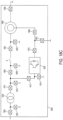
- FIG. 1 B Another configuration of a wind turbine is shown in Fig. 1 B , which employs an exciter based doubly fed machine (xDFM).
- Fig. IB an exciter machine 50 is connected between the DFIG 40 and the front-end converter side of the converter 30.
- a conventional brake chopper 20 is connected in the DC link of the converter 30, between the machine-side converter (MSC) 31 and a grid-side converter (GSC) 32.
- MSC machine-side converter
- GSC grid-side converter
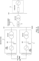
- Fig. 2 shows a wind turbine generator 10 equipped with a series active crowbar 21 connected between the stator of the DFIG 40 and the grid that is configured to protect the DFIG 40, the MSC 31, and the GSC 32.
- These options can be classified as a type of series connected, active, condition-based impedance change, FCL device.
- a resistive FCL network 21 is connected in series with the stator windings of the DFIG 40, as seen in Fig. 2 .
- the resistive FCL network 21 may include a resistance element Rcrow 22, which could be a set of three resistors each in parallel with bidirectional static switches 23a and 23b. These switches may be, for instance, composed of two gate turn-off thyristors (GTO) or integrated gate commutated thyristors (IGCT), connected in a back-to-back manner. A combination of a series and shunt active FCL networks may also be employed. An alternative to this is to connect the FCL device to a set of open-end terminals on the stator. These circuits may be complicated by the presence of the static switches, which, not only require the use of control and gate drive circuitry, but also need overvoltage protection during turn on.
- a family of series connected, active, and/or condition-based impedance change FCL devices that are connected outside the wind turbine may exist. These devices serve multiple wind turbine generators such as wind turbine generators in a wind farm. These devices have an inverter connected in series with the main power flow, so that a voltage can be injected to mitigate the transient caused by the voltage dip.
- inverter connected in series with the main power flow, so that a voltage can be injected to mitigate the transient caused by the voltage dip.
- FIG. 3 shows a single wire diagram of a super conductor FCL (SFCL) connected before the wind farm's interconnection point at the wind farm's Point of Common Coupling (PCC).
- the FCL employed at the wind farm level may be an SFCL 50.
- the SFCL 50 is placed outside of all the wind farm's wind turbines 10 between the PCC 51 and power grid network 52. Not only does the SFCL 50 placed between the PCC 51 and power grid network 52 serve multiple wind turbines to control fault currents but it may also suppress inrush currents, when a wind farm has adopted an SFCL at the system interconnection point.
- variable impedance network Another type of active condition-based FCL, also connected between the PCC and the power grid network, is based on a variable impedance network connected in a shunt manner to ground.
- a variable impedance network may be implemented using a variable inductor, which has a main winding for conducting alternating current and a DC control winding for conducting direct current.
- This type of inductor usually has the control winding wound in an orthogonal manner to the main flux in the core, so that the DC winding does not see any of the AC current, facilitating the control power supply.
- these wind farm level FCLs can help mitigate adverse effects on the wind turbine supply voltage, they do not ensure the protection of the wind turbine converter equipment under grid disturbances. Also, they do not help satisfy the compliance of the wind turbine with grid codes and customer requirements, since wind turbine validation usually is a type of test performed on an individual wind turbine, at its power input terminals. Accordingly, the conventional use of FCLs at the wind farm level does not help individual wind turbines comply with such grid codes and customer requirements. As such, there is a long-felt but unmet need to satisfy these grid code and customer compliance requirements at the individual wind turbine's interface with a network or grid, as well as to protect the wind turbine's converter, avoiding the need of expensive solutions at the wind farm level.
- EP2581601A1 discloses an electricity generation system that withstand voltage dips.
- the system comprises a first additional impedance connected in parallel between the generators rotor and the back-to-back converter, a second additional impedance connected to the stator and a control unit capable of governing the additional impedances.
- EP2293431A2 discloses a method and system for controlling a wind power plant in the event of power grid failures.
- the system comprises a resistive impedance connected to the generator, that short-circuits said generator when activated, and a switch for selectively activate or deactivate said resistance impedance.
- EP2472532A1 discloses a coil assembly and superconducting fault current limiter which can be used for connecting power generators, such as wind turbines, to a grid.
- WO9827635A1 discloses a device and method in an electric power plant for protection of an object (a generator for example) against over-currents from a grid, the system comprising a switching device connected between the grid and the object a said device being connected to the object y means of a line. The system further comprises an arrangement connected to the line, for reducing over-currents towards the object.
- WO03065567A1 discloses a wind turbine comprising an asynchronous generator configured to be electrically connected to a power grid connection, and a power converter circuit configured to be electrically connected to the asynchronous generator.
- a wind turbine includes a housing; an asynchronous generator disposed in the housing and configured to be electrically connected to a power grid connection; a power converter circuit disposed in the housing and configured to be electrically connected to the asynchronous generator; and a variable inductive impedance device disposed in the housing, connected between the power converter circuit and the rotor of the generator and configured to limit current by varying impedance in response to a transient current.
- variable inductive impedance device being selected among a group consisting of a variable inductor, a magnetic amplifier and saturable core fault current limiter, a diode-bridge fault current limiter with DC biased coil, and an embedded magnet and saturable core fault current limiter device.
- the wind turbine further includes a fixed impedance device connected in parallel with the variable impedance device.
- variable impedance device is a variable inductor.
- fixed impedance device is a resistor
- variable impedance device is connected in a shunt arrangement between the asynchronous generator and a neutral point.
- the wind turbine further includes a controller configured to control the variable impedance device in response to detection of the transient current to vary impedance.
- variable impedance device limits current by passively varying impedance in response to the transient current.
- the wind turbine further includes a second variable impedance device disposed in the housing, electrically connected to the asynchronous generator, and configured to vary impedance in response to the transient.
- the wind turbine delivers reactive power to the power grid when the variable impedance device varies impedance in response to the transient current.
- a method for controlling current in a wind turbine includes generating a current using an asynchronous generator disposed in a housing of the wind turbine; converting the current using a power converter circuit disposed in the housing; limiting the converted current in response to a transient current in a power grid by varying impedance of a variable impedance device selected among a group consisting of a variable inductor, a magnetic amplifier and saturable core fault current limiter, a diode-bridge fault current limiter with DC biased coil, and an embedded magnet and saturable core fault current limiter device, disposed in the housing and electrically connected between the power converter circuit and the rotor of the asynchronous generator; and outputting the limited current to a connection to the power grid.
- a variable impedance device selected among a group consisting of a variable inductor, a magnetic amplifier and saturable core fault current limiter, a diode-bridge fault current limiter with DC biased coil, and an embedded magnet and saturable core fault current limiter
- the method further includes controlling the variable impedance device in response to detection of the transient current to vary impedance.
- the method further includes the variable impedance device limiting current by passively varying impedance in response to the transient current.
- module refers to a unit that can perform at least one function or operation and may be implemented utilizing any form of hardware, software, or a combination thereof.
- variable impedance devices includes the connection of variable impedance devices to a wind-turbine, in a location as defined in the claims, that achieves a substantial limitation of the converter currents and voltage during a transient created by a voltage dip or any other grid disturbance.
- the variable impedance devices will be understood as being additional devices installed in the wind turbine, and not as component part of the installation necessary for the generation of electrical power from the wind that, because of their construction or characteristics, happen to change their impedance depending on the operating conditions, such as a conductor's impedance change with frequency or a transformer's or generator's saturation with high currents.
- variable impedance device such as, for example, a conductor's impedance change with frequency, or a transformer's or generator's saturation.
- the FCL devices can be of the active or passive, "condition-based impedance change" type, so that they change impedance during the transient, with or without the intervention of any external control circuit.
- condition-based impedance change type, so that they change impedance during the transient, with or without the intervention of any external control circuit.
- a shunt manner for instance between the rotor-side windings of a DFIG machine and the machine side converter (MSC) they will include a variable impedance network of the active "condition-based impedance change" type.
- the system components within the wind turbine are electrically connected to each other. Being electrically connected means an electrical path exists between the system components which mayor may not have other components therebetween.
- the system components may be electrically connected in parallel, series, shunt, and/or a combination of these arrangements. Further, the system components may be electrically connected to each other through other elements or may be directly connected to each other. For example multiple resistors may be electrically connected in series. Further, the first and last resistors are electrically connected to each other despite the intervening resistors being connected therebetween.
- a variable impedance device which may be designed to limit current to a generator as its function is electrically connected to the generator, while possibly having other elements therebetween.
- system components may include a generator, a converter, a variable impedance device, an FCL, a resistor, and/or a transformer. Accordingly, devices, elements or other components described as connected will be understood to be electrically connected unless otherwise specified.
- a variable impedance device is configured such that it will respond to current as opposed to a voltage.
- a high current level may drive the inductor out of saturation where the inductor is normally saturated by the presence of an embedded magnet.
- the variable impedance device is implemented with a superconducting FCL (SFCL). In this case a high current level will force the device out of the superconducting region.
- SFCL superconducting FCL
- a controllable inductor is placed in series with the stator and grid connection and is controlled by a control system that responds to a current increase detected by a current sensor.
- variable impedance device is a variable resistive element.
- a variable impedance device may be connected in series with a rotor winding of a DFIG wind turbine.
- the variable impedance device may still operate in an automatic, but passive, manner.
- the variable impedance device may be actively controlled using a control circuit. In both cases the variable impedance device is configured such that it reacts in response to a current, or current transient as may be the case.
- a rotor overvoltage is produced as a consequence of grid voltage dips.
- a variable impedance device is connected in series to the rotor windings and designed to increase its impedance when the voltage at its terminals decreases, the resulting effect might not be beneficial. In this case, the impedance would not increase when a voltage dip occurs.
- a solution is to use an impedance that changes with current flow instead of voltage for passive type devices, or a control based on current measurement instead of voltage for active type devices.
- the series variable impedance device may be implemented using any of a variety of devices where the selected device may be placed in any of a variety of locations in the power circuits in the wind turbine. Further, according to one or more exemplary embodiments the variable impedance device may also be used in a series and/or in a shunt arrangement.
- a wind turbine 400 includes a variable impedance device 410 connected in series between a generator 440 (which can have a stator 444 and a rotor 442) and a transformer 430.
- the variable impedance device is connected in series between the generator and the grid directly without a transformer, and is located with the generator within the wind turbine housing.
- the embodiments described here can be used with other wind turbine configurations in which the main step up/down transformer has different connection points and rated power ( Fig. 18 ).
- variable impedance device employed will depend on the specific wind turbine configuration. In each case, the voltage level may be different in the different locations where the variable impedance device could be connected, and because of the different impedances of each transformer type, the maximum current and voltage levels the variable impedance device should withstand may vary.
- the arrangement may include other conventional system components for the generation of power, such as, for example, a power converter circuit 420 connected between the generator 440 and the transformer 430, parallel to the variable impedance device 410. Accordingly, the wind turbine, using the power converter circuit 420 and/or the transformer 430, converts the current by changing the current from either AC to DC or DC to AC, changing a voltage, and/or changing a frequency.
- a power converter circuit 420 connected between the generator 440 and the transformer 430, parallel to the variable impedance device 410. Accordingly, the wind turbine, using the power converter circuit 420 and/or the transformer 430, converts the current by changing the current from either AC to DC or DC to AC, changing a voltage, and/or changing a frequency.
- the arrangement may include additional system components such as, for example, a fixed-value impedance device, which may be a resistor RA 450, connected in parallel across the variable impedance device 410.
- the resistor may be a fixed value resistor connected in parallel with the variable impedance device and may have a fixed resistance in both a passive state or OFF state, when the resistor does not have current or voltage across it, and an active state or ON state.
- the variable impedance device 410 may have a low value during normal operation when inductance and impedance are both low. However, when a transient current is incident onto the system shown in Fig.
- variable impedance device 410 inducing high impedance, the variable impedance device 410, by increasing its impedance, shunts the current through the resistor RA thereby dissipating power. This arrangement may further lower the time response of the overall circuit making it respond and stabilize quickly.
- the variable impedance device 410 may, for example, use any of the passive non-controlled variable impedance devices described here, or equivalent devices. Alternatively, a controlled variable impedance device, such as those described here or equivalent devices, may be used for the variable impedance device 410.
- the fixed impedance device may be a fixed-value resistor RA connected in parallel across the variable impedance device 410.
- the resistor RA may be sized so that it has only a small amount of current flowing through it during normal operation when inductance and impedance are both low.
- the variable impedance device 410 increases its impedance which shunts most of the current through the resistor RA to dissipate power. This arrangement, because of the L/R time constant, may further speed the response of the overall circuit making it respond and stabilize quickly.
- Leq is primarily defined by the combined leakage inductance of the stator and rotor windings.
- Req is defined by the sum of the series resistance of the stator and rotor windings, any series resistance that may be placed in series with the stator windings, such as the resistance RA in parallel with the variable impedance device 410 shown in Fig. 4A , and the crowbar resistance shown in Fig 1 (or any series resistance connected in a shunt manner to the rotor windings).
- a resistor connected in a shunt manner with the stator windings may have little or no effect in the mitigation of the current transient for a DFIG system.
- a current transient in a typical 3 MW DFIG generator may have a time constant of around 30 ms, with the total transient duration being about 150 ms, regardless of the duration of the voltage dip that initiated the transient.
- This example contemplates a shunt or crowbar resistor connected at the rotor side, or a brake chopper resistor connected at the DC link with a value of 0.15 Ohms, in a topology like that shown in Figs. 1 A or 1 B .
- a variable impedance device 411 may be included and connected in series with a resistor RB 451 to form a shunt variable impedance network. That shunt variable impedance network is connected at one end to the rotor windings of the generator 440 and the power converter system 420 in a shunt manner, while the other end may be connected to a neutral point 460.
- a neutral point 460 may be a point with a different voltage level, such as a ground potential, such as a system ground or earth ground, or may be an arrangement where the impedance network is left open depending on the resistor network RB 451 arrangement, for example a wye or delta resistor arrangement.
- the variable impedance 411 may be of the active type, presenting a high value in normal operation and a low value in the event of a fault.
- variable impedance device 412 there may be another variable impedance device 412 connected in series between the power converter and the rotor windings of the generator 440.
- This impedance device which presents a low value during normal operation and a high value during the fault event, can be either of the passive type or of the active type.
- the shunt variable impedance network similar to the shunt variable impedance network shown in Figure 4B , formed as the series connection of an active variable impedance device 413 and a resistor Rc 452, is connected to the series variable impedance device 412 and the generator 440.
- any of the devices shown in Figs. 4A through 4C are placed within a single housing, wherein the housing may include the entire wind turbine structure, or may be specifically placed within a housing such as a nacelle of a wind turbine.
- the overall DFIG wind turbine configurations shown in Figs.4B and 4C are placed within a single housing, wherein the housing may include the entire wind turbine structure, or may be specifically placed within a housing such as a nacelle of the wind turbine.
- Fig. 5 shows a detailed view of a configuration of a DFIG power conversion circuit 520 which may be implemented in one or more of the exemplary embodiments.
- the power converter circuit 420 as shown in Figs. 4A-4C may be implemented as the DFIG power conversion device 520 shown in Fig. 5 .
- the power conversion circuit may include a grid-side filter 525, a grid-side converter (GSC) 522, an energy storage element, typically a capacitor bank 523 (although other elements such that inductors could also be used), a machine-side converter (MSC) 521, and a machine-side filter 524.
- GSC grid-side converter
- MSC machine-side converter
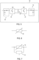
- the series variable impedance device can be a standalone variable impedance network 600 as shown in Fig. 6 , which can be of either the active or passive type.
- the series variable impedance device may be formed by a variable impedance network 704 combined with a fixed impedance branch Z 705, typically resistive, connected in parallel as shown in Fig. 7 .
- the standalone variable impedance 600 or the variable impedance network shown in Fig. 7 can be a variable inductor as shown in Fig. 8 which shows a variable impedance device or network 801 of either the active or passive type, to form part of a "condition-based impedance change" FCL device according to an exemplary embodiment.
- Fig. 9 shows a variable inductor in an active variable impedance device as a "condition-based impedance change" type FCL device.
- the active variable impedance device includes an inductor 900 that is controlled by a control winding 901 which is connected to a controlled current source 903, which may be a DC supply source.
- the variable inductor has a main winding 900 to conduct the AC current, and an auxiliary winding 901, typically connected in an orthogonal manner to the same magnetic core, which is connected to the controlled current source 903 that supplies a current Id, to vary the inductance value.
- variable impedance devices Examples of passive variable impedance devices that can be used as the variable impedance devices shown in Figs. 4A-4C , as illustrated in Figs. 10-13 .
- Fig. 10 shows an example not being part of the invention, of a series SFCL device.
- the series connected SFCL device includes a super conductive coil Rsc and a resistive and/or inductive impedance Rshunt/Lshunt that is connected in parallel across its terminals.
- the impedance of the superconducting coil increases, and the resultant SFCL impedance is determined mainly by the parallel connected impedance branch, which results in a fault current reduction.
- An example of such an SFCL device is the superconducting cable tie with inherent fault current limiter capabilities.
- An alternative to the device shown in Fig. 10 is the Shielded-Core FCL, whereby a cryogenic chamber is isolated from the high-voltage region by means of a series-connected transformer.
- Fig. 11 shows an example of a magnetic amplifier or saturable core FCL device.
- the figure shows an electric arrangement.
- Fig. 11 shows another example of the "condition-based impedance change", passive type FCL formed with a magnetic amplifier or saturable core.
- the device shown in Fig. 11 employs two magnetic cores, each having an AC coil winding, and being electrically connected in series.
- the cores are permanently saturated by a DC winding that is wound around the two cores. By doing so, not only are the two cores saturated by DC, but, by providing the two AC coils with the same number of turns, the resultant AC flux is cancelled out, enabling the use a simple pure DC current source.
- each of the magnetic cores comes out of saturation in alternative half cycles, imposing a fault limiting impedance.
- the use of superconducting materials in the dc-coil to make the device a SFCL can be appreciated.
- FCLs are not directly connected to wind turbines, but merely are placed such that they increase the fault current protection level of the network and substation of wind farms which are made up of wind turbines.
- the insertion of the FCL may reduce the fault current level making it possible to use conventional cabling and switchgear.
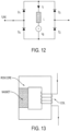
- Fig. 12 shows a diode-bridge FCL with a DC biased coil and external DC voltage source.
- a DC coil that can be implemented using superconducting wire, four diodes, and a DC voltage source that imposes a circulating DC current 10.
- the 10 current forward biases the four diodes.
- the diodes D3 and D4, or DJ and D2 may become reverse-biased during the positive or negative half cycle respectively.
- the FCL device imposes an inductance L that limits the fault current level.
- the devices shown on Fig. 11 and Fig. 12 could also be actively controlled, although they may have a limited operation range.
- the fault current limiting threshold may be adjusted within a certain range.
- Fig. 13 illustrates an example of an embedded magnet, saturable core FCL device schematic.
- a similar kind of saturable core may have a permanent magnet embedded in the core, as shown in Fig. 13 .
- the magnet is in a demagnetized state. Its permeability is close to the air value and the Magnetic FCL (MFCL) behaves like an air-cored reactor with a low inductance.
- MFCL Magnetic FCL
- the fault current drives the magnetic field beyond the magnet's coercive value.
- the magnet becomes magnetized and closes the flux path through the magnetic circuit.
- the inductance of the device is increased which reduces the fault current level.
- Fig. 14 shows an active variable impedance connected in a series manner.
- Fig. 14 shows a variable impedance device, specifically, a variable inductor of the, "condition-based impedance increase" type FCL device.
- the variable impedance device may include a control circuit 1407 which is connected to a variable impedance device 1408.
- a variable impedance of the active, "condition-based impedance change" type, as that shown in Fig. 9 could also be used instead of the passive type.
- a control circuit 1407 sends a command to vary the impedance value of the variable impedance device 1408, upon detection of the main current having risen above a certain threshold value.
- Fig. 15 shows a variable impedance device 1508 connected in a shunt manner.
- the variable impedance may either form a three-wire circuit or a four-wire circuit, if connected to ground or any other convenient point in the circuit.
- a control circuit 1507 sends a command signal the variable impedance device 1508 depending on the current level measured on the line.
- variable inductor shown in Fig. 15 is an active "condition-based impedance change" type FCL device.
- the FCL device may have a main winding to conduct the AC current, and an auxiliary winding, that typically would be arranged in an orthogonal manner to the same magnetic core, connected to a DC supply source, to vary the inductance value.
- Fig. 16 shows a variable impedance device 1608 connected in a shunt manner in series with a fixed impedance network 1609.
- the variable impedance may either form a three-wire circuit or a four- wire circuit, if connected to ground or any other convenient point in the circuit.
- the variable impedance device 1608 is connected to a control circuit 1607. When the current is low, or in a range of normal operation, the control circuit 1607 sends a command signal to the variable inductor 1608 that maintains a high impedance value in the variable inductor 1608. Consequently, the resultant impedance of the shunt branch formed by elements 1608 and 1609 being connected in series is high, and a negligible amount of current flows through them.
- the control circuit 1607 sends a signal to the variable impedance 1608 causing it to reduce its impedance value. Then, the shunt impedance is lowered and the line current is diverted into it, depending on the value of the variable impedance. Lf the value of the variable impedance becomes very low, the impedance of the shunt branch is equivalent to the impedance of the fixed impedance network 1609.
- Figure 17 illustrates a wind turbine 700 which includes a nacelle 710 fixed to the top of a pedestal 720.
- the nacelle 710, the pedestal 720, or a combination of the nacelle and the pedestal can form the housing for the wind turbine.
- the nacelle 710 includes the generator, the power converter circuitry as well as other electronic gear.
- the variable impedance device and its associated components can be installed within the nacelle or within the pedestal of the wind turbine 700.
- Figure 18 shows locations in a wind turbine where series and/or shunt variable impedance devices of the condition-based impedance change type FCL may be placed.
- One or more exemplary arrangements not according to the invention may include a variable impedance FCL device connected in series with the main power flow at one or more of the locations in a wind turbine shown by either one or more of FCL devices 1801, 1802, 1804, 1808, 1810, 1811, and 1813, shown in the locations in Figs. 18A through 18C .
- the device 1809 could also be connected in a wye or delta fashion to the left-hand-side of the stator open end winding terminals, providing that a stator open-end winding configuration is available.
- These series devices may be of the passive, "condition-based impedance change" type.
- an active device will also serve for the purpose of the one or more exemplary embodiments.
- One or more exemplary arrangements may also have a FCL device connected in a shunt arrangement with the main power flow.
- FCL devices 1803, 1805, 1806, 1807, 1812, and 1814 can be placed in the locations within a wind turbine as shown in Figs. 18A - 18C .
- These devices are of the active "condition-based impedance change" type FCL and include a variable impedance network 1508, as shown in Fig. 15 , or a combination of a variable impedance networks with a fixed impedance network 1609, typically resistive, as shown in Fig. 16 .
- variable impedance network presents a high impedance value during normal operation, and presents a comparatively much lower impedance value in the presence of fault current levels.
- the impedance change is controlled by a control system 1607 that may sense the main current and acts when that current rises above a certain threshold value.
- a control system 1607 may sense the main current and acts when that current rises above a certain threshold value.
- Such a variable impedance device can be implemented by the active or controlled variable inductor shown in Fig. 9 .
- One or more exemplary arrangements could also include anyone or more of the series connected FCL devices 1801, 1802, 1804, 1808, 1810, 1811, and 1813, in combination with anyone or more of the shunt connected FCL devices 1803, 1805, 1806, 1807, 1812, and 1814, shown in Figs. 18A-18C .
- Fig. 18A shows a DFIG wind turbine configuration that includes a generator 1840 that has a stator and a rotor where the stator, rotor, and grid voltage supply present different voltage levels.
- a step up/down transformer 1830 may be provided to meet the different voltage levels.
- Fig. 18B shows a DFIG wind turbine configuration that includes a generator 1840 that has a stator and a rotor where the stator and the grid voltage supply present the same voltage, but is different to that of the rotor.
- a step up/down transformer 1830 may be provided to meet the different voltage levels.
- Fig. 18C shows a DFIG wind turbine configuration that includes a generator 1840 that has a stator and a rotor where the stator and the rotor present the same voltage, but that voltage is different from that of the grid.
- a step up/down transformer 1830 may be provided to meet the different voltage levels.
- a difference between the structures shown in Fig. 18B and 18C is in the voltage rating of the stator of the wind turbine machine in each figure.
- variable impedance devices which may be FCL components, within a wind turbine, such as, for example, devices 1802 and 1807, 1804 and 1806, and 1801 and 1805, etc.
- one or more exemplary arrangements do not require all the individual FCL elements as shown, and may implement as many as only one of the FCLs.
- the FCL placement as shown in Figs. 18A through 18C may be understood as being anyone, more than one, or all of the FCLs shown, or any combination thereof.
- Figs. 18A through 18C show a plurality of the different options for placement of an FCL, or combination of FCLs, within the wind turbine.
- anyone FCL placed in anyone of the indicated locations may be sufficient to suppress an electrical transient.
- one or more exemplary arrangements could include only one variable impedance device connected in series as shown in Fig. 4A .
- a switch S typically may be installed in the wind turbine to isolate the stator windings. With use of the variable impedance device in the various arrangements described here, the switch can stay closed during a fault so that the generator stays connected to the grid to provide a fault ride through capability. Further, there may be more than one such switch of this kind, depending on the particular embodiment. For instance, an additional switch may be installed between a converter 1820, which may be a back-to back (B2B) converter, and a transformer 1830.
- B2B back-to back
- the FCL devices described herein may change impedance in discreet and defined steps.
- the FCL devices may present a continuous variation of impedance values.
- the FCL devices also could serve the additional purpose of mitigating or damping a possible resonance, for instance resonance occurring due to the interaction of the grid with the wind turbine converter, like the grid-side filters.
- wind turbine configurations shown in Figs. 18A through 18C may be entirely placed within a single housing 1850, wherein the housing may include the entire wind turbine structure, or may be specifically placed within a housing such as a nacelle of the wind turbine.
- one or more of a devices 1809 may be connected in a wye or delta fashion to the stator open end winding terminals, provided the stator open-end winding configuration is present, as shown in Figs. 19A and 19B .
- rotor leakage inductance Xr as well as stator leakage inductance XS is shown in a stator open-end winding configuration.
- Fig. 19A shows a stator open-end winding configuration in a delta connection arrangement.
- Fig. 19B shows a stator open-end winding configuration in a wye connection arrangement.
- variable impedance devices 1809 are placed in a one or more arrangements and locations as shown in Figs. 19A and 19B .
- variable impedance devices 1809 may be included in the stator winding in one of the locations as shown in Figs. 19A and 19B .
- all of the shown variable impedance devices 1809 may be included as shown, or a sub-combination, for example only two of the variable impedance devices, may be included.
- variable impedance device 2010, for example a fault current limiter described here, can be installed in individual wind turbines so that at the PCC, an individual wind turbine satisfies regulatory and/or customer electrical requirements during low voltage conditions. Further, by installing the variable impedance device 2010 within an individual wind turbine and in close proximity to the power converter 2020, the variable impedance device 2010 may also operate to protect the wind turbine's power converter 2020 from damage due to excessive currents caused by a low voltage event, provided that it has been designed for that purpose.
- variable impedance device 2010, which can be implemented with the series variable inductors described herein and shown in the figures, are installed within close proximity to the wind turbine's generator 2040 and power converter 2020 and eventually are installed within the same housing of the wind turbine that encloses the generator and power converter.
- a variable impedance device 2010, such as an FCL, a generator 2040 (which includes a stator 2044 and a rotor 2042), and a power converter 2020, which may be a back-to-back (B2B) converter, as well as a transformer 2030 may be placed within the same housing 2050, as shown. Further, these elements may be specifically placed within the nacelle of the wind turbine.
- Prior systems that use resistive circuits to dissipate active power during a fault do not deliver substantial or sufficient reactive power from the rotor or the stator to satisfy grid code requirements, or are not able to deliver it as fast as it is required, since the injection is not controlled while the crowbar is connected.
- Exemplary embodiments of the invention can supply substantial reactive power to the grid during a fault in both the shunt connected variable impedance device configuration and the series connected variable impedance device configuration.
- Exemplary embodiment that employ a shunt connected variable impedance device such as the embodiments shown in Fig. 4B and 4C , and various configurations shown in Figs. 18A -C , allow required amounts of reactive power to be provided from the stator to the grid with an appropriate sizing of the variable impedance device. Since rotor or stator terminals are not short circuited through a resistor in these embodiments, reactive power is delivered to the grid when the variable impedance device is designed to vary it's impedance within a certain impedance range. In the case where the variable impedance device is an inductor, the inductance changes in a range between a minimum value Lmin and a maximum value Lmax. These values are selected depending on the installation components and specific requirements or customer's specifications, such voltage profiles (low voltage ride through and high voltage ride through) that the system should be able to withstand, the reactive current injection levels and times, and the power converter's components that should be protected.
- Exemplary arrangements that employ a series connected variable impedance device such as the arrangement shown in Fig. 4A , various configurations shown in Figs. 18A-C , and the embodiment shown in Fig. 19 , allow reactive power to be provided from the stator to the grid with an appropriate sizing of the variable impedance device.
- the mechanical torque control dynamic is so low that an acceleration of the generator during the beginning of the fault is produced.
- the fixed impedance device RA 450 which is connected in parallel to the variable impedance device, dissipates active power and thus maintains the generator's speed while the variable impedance device delivers reactive current to the grid.
Claims (11)
- Une turbine éolienne comprenant :un générateur asynchrone (440; 1840) configuré pour être connecté électriquement à une connexion au réseau électrique ;un circuit convertisseur de puissance (420; 1820) configuré pour être connecté électriquement au générateur asynchrone (1840) ; etun dispositif à impédance variable (411; 412; 413; 600; 704; 801; 900; 1408; 1508; 1608) connecté entre le circuit convertisseur de puissance (420) et le rotor (442) du générateur (440, 1840)caractérisé en ce que l'éolienne comprend en outreun boîtier (1850), le générateur asynchrone (440; 1840) et le circuit convertisseur de puissance (420; 1820) étant disposés dans le boîtier (1850) ;le dispositif à impédance variable (411; 412; 413; 600; 704; 801; 900; 1408; 1508; 1608) disposé dans le logement (1850) et configuré pour limiter le courant en faisant varier l'impédance en réponse à un courant transitoire, et étant sélectionné parmi un groupe constitué deune inductance variable,un amplificateur magnétique et un limiteur de courant de défaut à noyau saturable (MFCL),un limiteur de courant de défaut à pont de diodes avec bobine polarisée en courant continu, etun dispositif limiteur de courant de défaut à aimant incorporé et noyau saturable.
- Turbine éolienne selon la revendication 1, dans laquelle le dispositif à impédance variable est une inductance variable.
- Turbine éolienne selon la revendication 1 ou 2, dans laquelle le dispositif à impédance variable (411; 412; 413; 600; 704; 801; 900; 1408; 1508; 1608) est connecté en dérivation entre le générateur asynchrone (440; 1840) et un point neutre.
- Turbine éolienne selon la revendication 3, comprenant en outre un dispositif à impédance fixe (RB; 451; RC; 452; 1609) connecté en série avec le générateur asynchrone (440; 1840) et le dispositif à impédance inductive variable (411; 412; 413; 600; 704; 801; 900; 1408; 1508; 1608).
- Turbine éolienne selon l'une quelconque des revendications 1 - 4, comprenant en outre un contrôleur configuré pour commander le dispositif à impédance variable (411; 412; 413; 600; 704; 801; 900; 1408; 1508; 1608) en réponse à la détection du courant transitoire pour faire varier l'impédance.
- Turbine éolienne selon l'une quelconque des revendications 1 - 4, dans laquelle le dispositif à impédance variable (411; 412; 413; 600; 704; 801; 900; 1408; 1508; 1608) limite le courant en faisant varier passivement l'impédance en réponse au courant transitoire.
- Turbine éolienne selon l'une quelconque des revendications 1 - 6, comprenant en outre un deuxième dispositif d'impédance variable disposé dans le boîtier (1850), connecté électriquement au générateur asynchrone (440; 1840), et configuré pour faire varier l'impédance en réponse au transitoire.
- Turbine éolienne selon l'une quelconque des revendications 1 - 7, dans laquelle la turbine éolienne délivre une puissance réactive au réseau électrique lorsque le dispositif à impédance variable (411; 412; 413; 600; 704; 801; 900; 1408; 1508; 1608) varie l'impédance en réponse au courant transitoire.
- Procédé de contrôle du courant dans une turbine éolienne, le procédé comprenant:générer un courant en utilisant un générateur asynchrone (440; 1840) disposé dans un boîtier (1850; 2050) de la turbine éolienne ; etconvertir le courant en utilisant un circuit convertisseur de puissance (420 ; 1820) disposé dans le logement (1850 ; 2050);caractérisé en ce que le procédé comprend en outrelimiter le courant converti en réponse à un courant transitoire dans un réseau électrique en faisant varier l'impédance d'un dispositif à impédance variable (411; 412; 413; 600; 704; 801; 900; 1408; 1508; 1608) sélectionné parmi un groupe constitué d'une inductance variable, d'un amplificateur magnétique et d'un limiteur de courant de défaut à noyau saturable (MFCL), d'un limiteur de courant de défaut à pont de diodes avec une bobine polarisée en courant continu, et d'un dispositif de limiteur de courant de défaut à aimant intégré et à noyau saturable, disposé dans le boîtier (1850) et connecté électriquement entre le circuit convertisseur de puissance (420) et un rotor (442; 2042) du générateur asynchrone (440; 1840); etdélivrer le courant limité à une connexion au réseau électrique.
- Procédé selon la revendication 9, comprenant en outre la commande du dispositif à impédance variable (411; 412; 413; 600; 704; 801; 900; 1408; 1508; 1608;) en réponse à la détection du courant transitoire pour faire varier l'impédance.
- Procédé selon la revendication 9, comprenant en outre le dispositif à impédance variable (411; 412; 413; 600; 704; 801; 900; 1408; 1508; 1608) limitant le courant en faisant varier passivement l'impédance en réponse au courant transitoire.
Applications Claiming Priority (2)
| Application Number | Priority Date | Filing Date | Title |
|---|---|---|---|
| US201361917538P | 2013-12-18 | 2013-12-18 | |
| PCT/IB2014/003222 WO2015092553A2 (fr) | 2013-12-18 | 2014-12-17 | Dispositif à impédance variable pour une turbine éolienne |
Publications (3)
| Publication Number | Publication Date |
|---|---|
| EP3084907A2 EP3084907A2 (fr) | 2016-10-26 |
| EP3084907C0 EP3084907C0 (fr) | 2023-06-07 |
| EP3084907B1 true EP3084907B1 (fr) | 2023-06-07 |
Family
ID=52997473
Family Applications (1)
| Application Number | Title | Priority Date | Filing Date |
|---|---|---|---|
| EP14856785.2A Active EP3084907B1 (fr) | 2013-12-18 | 2014-12-17 | Dispositif à impédance variable pour une turbine éolienne |
Country Status (4)
| Country | Link |
|---|---|
| US (1) | US10352304B2 (fr) |
| EP (1) | EP3084907B1 (fr) |
| ES (1) | ES2950289T3 (fr) |
| WO (1) | WO2015092553A2 (fr) |
Families Citing this family (28)
| Publication number | Priority date | Publication date | Assignee | Title |
|---|---|---|---|---|
| CN104704701B (zh) * | 2012-10-08 | 2018-03-06 | 维斯塔斯风力系统集团公司 | 线路阻抗补偿系统 |
| US9917475B2 (en) * | 2013-11-08 | 2018-03-13 | Eaton Corporation | Variable neutral impedance for multi-source system |
| JP6071912B2 (ja) * | 2014-01-27 | 2017-02-01 | 株式会社東芝 | 過電圧保護装置および電流調整回路 |
| CN105140963B (zh) * | 2015-09-21 | 2017-11-17 | 哈尔滨理工大学 | 基于故障限流控制的双馈风力发电机系统及低电压穿越方法 |
| EP3365964A4 (fr) * | 2015-10-23 | 2019-05-29 | The University of Hong Kong | Sucette d'ondulation prête à l'emploi pour liaisons à tension continue dans des systèmes d'électronique de puissance et des réseaux électriques à courant continu |
| EP3447891A1 (fr) * | 2016-04-19 | 2019-02-27 | Ingeteam Power Technology, S.A. | Procédé de filtrage pour le côté alternatif d'un système de conversion de puissance et système de conversion de puissance |
| US10063172B2 (en) * | 2016-12-27 | 2018-08-28 | General Electric Company | Controlled braking of a generator |
| US10172760B2 (en) | 2017-01-19 | 2019-01-08 | Jennifer Hendrix | Responsive route guidance and identification system |
| US10396695B2 (en) * | 2017-04-18 | 2019-08-27 | General Electric Company | Method for protecting an electrical power system |
| US10587121B2 (en) * | 2017-05-23 | 2020-03-10 | General Electric Company | Electrical power systems and subsystems |
| US10468881B2 (en) * | 2017-05-31 | 2019-11-05 | General Electric Company | Electrical power systems having zig-zag transformers |
| NO342169B1 (no) * | 2017-06-08 | 2018-04-09 | Frode Olsen | Vindmølle med elektronisk giring og regulerbar / justerbar stator |
| US11502634B2 (en) * | 2017-07-25 | 2022-11-15 | Mitsubishi Electric Corporation | Driving device, compressor, air conditioner, and driving method |
| NO342487B1 (no) * | 2017-09-01 | 2018-05-28 | Frode Olsen | Motor/Generator/Maskindel/Battericelle. Enhet med elektronisk giring over flere trinn, fra enhetene på begge sidene, og inn mot enhet i senter. |
| CN111316521B (zh) * | 2017-09-15 | 2023-06-20 | 通用电气公司 | 用于控制连接到电力网的电功率系统的系统和方法 |
| US10763674B2 (en) * | 2017-09-29 | 2020-09-01 | General Electric Company | System and method for controlling cluster-based wind farms |
| US10819103B2 (en) * | 2017-12-07 | 2020-10-27 | General Electric Company | Systems and methods for isolating faults in electrical power systems connected to a power grid |
| US10971926B2 (en) * | 2018-02-23 | 2021-04-06 | Varian Semiconductor Equipment Associates, Inc. | Tape lifetime monitor in fault current limiter |
| US10615727B2 (en) * | 2018-08-27 | 2020-04-07 | General Electric Company | Dynamic brake circuit assembly for a wind turbine |
| CN110165676A (zh) * | 2019-05-08 | 2019-08-23 | 华北电力大学 | 具备故障限流及断路功能的复合型直流潮流控制器 |
| EP3764503B1 (fr) * | 2019-07-09 | 2023-08-30 | General Electric Renovables España S.L. | Commande et fonctionnement de convertisseur de puissance |
| EP3843227A1 (fr) * | 2019-12-23 | 2021-06-30 | Nordex Energy SE & Co. KG | Éolienne à double alimentation dotée d'un transformateur moyenne tension |
| CN111884229B (zh) * | 2020-08-19 | 2022-03-08 | 南方电网科学研究院有限责任公司 | 背靠背柔性直流输电系统的异同步控制方法及系统 |
| EP3975367A1 (fr) * | 2020-09-29 | 2022-03-30 | Siemens Gamesa Renewable Energy Innovation & Technology S.L. | Système d'alimentation électrique d'une éolienne |
| US11831271B1 (en) * | 2021-06-09 | 2023-11-28 | Aderis Energy, Llc | Medium voltage inrush current regulation and interconnection control system and method |
| CN113555860B (zh) * | 2021-07-28 | 2022-08-19 | 国网甘肃省电力公司 | 改进型桥式超导故障限流器及其阻值调节方法 |
| CN113746140B (zh) * | 2021-11-08 | 2022-02-11 | 四川大学 | 一种高压直流输电连续扰动下的双馈风机故障穿越方法 |
| CN114974795B (zh) * | 2022-04-14 | 2023-08-01 | 西安交通大学 | 一种变阻抗超导限流变压器及其工作方法 |
Family Cites Families (38)
| Publication number | Priority date | Publication date | Assignee | Title |
|---|---|---|---|---|
| US2402258A (en) | 1943-01-21 | 1946-06-18 | Automatic Elect Lab | Electrical signaling system |
| US2578235A (en) | 1946-12-26 | 1951-12-11 | Clark Controller Co | Phase shifting system |
| US2731590A (en) * | 1954-07-21 | 1956-01-17 | Smith Bob Hugh | Polyphase voltage generator |
| US3293447A (en) * | 1963-04-10 | 1966-12-20 | Ibm | Parametric tunnel-diode amplifier frequency converter using pump harmonic |
| US3443206A (en) * | 1966-07-05 | 1969-05-06 | Frank R Bradley | Compensation circuits for voltage dividers |
| US4434376A (en) * | 1979-07-23 | 1984-02-28 | Electric Power Research Institute, Inc. | Method and means for damping subsynchronous oscillations and DC offset in an AC power system |
| US4347539A (en) * | 1981-06-03 | 1982-08-31 | Westinghouse Electric Corp. | Electrical equipment protective apparatus with energy balancing among parallel varistors |
| DE4025557A1 (de) | 1990-08-11 | 1992-02-13 | Kugelfischer G Schaefer & Co | Stromgenerator |
| US5127085A (en) | 1991-04-01 | 1992-06-30 | General Motors Corporation | Ride-through protection circuit for a voltage source inverter traction motor drive |
| JP3029185B2 (ja) | 1994-04-12 | 2000-04-04 | キヤノン株式会社 | 単独運転防止装置、それを用いた分散型発電装置及び発電システム |
| US5902506A (en) | 1995-12-08 | 1999-05-11 | Thermatool Corp. | Matching apparatus for connecting high frequency solid state electrical power generator to a load |
| JP2001505758A (ja) | 1996-12-17 | 2001-04-24 | アセア、ブラウン、ボベリ、アクチエボラーグ | 過電流低減および電流制限によって対象物を過電流に対して保護する装置および方法 |
| US6958550B2 (en) | 1998-04-02 | 2005-10-25 | Capstone Turbine Corporation | Method and system for control of turbogenerator power and temperature |
| AU2002246920A1 (en) | 2000-10-27 | 2002-08-06 | Emerson Electric Co. | Uninterruptible power supply |
| US6787933B2 (en) | 2001-01-10 | 2004-09-07 | Capstone Turbine Corporation | Power generation system having transient ride-through/load-leveling capabilities |
| EP1470633A1 (fr) * | 2002-01-29 | 2004-10-27 | Vestas Wind System A/S | Circuit con u pour etre utilise dans une installation d'energie eolienne |
| AU2002368205A1 (en) | 2002-09-13 | 2004-04-30 | Abb Ab | Wind power fed network |
| US7233129B2 (en) | 2003-05-07 | 2007-06-19 | Clipper Windpower Technology, Inc. | Generator with utility fault ride-through capability |
| ATE377286T1 (de) * | 2003-07-15 | 2007-11-15 | Gamesa Innovation & Tech Sl | Steuer- und schutzgerät für ein doppelgespeistes induktionsgeneratorsystem |
| ES2245608B1 (es) | 2004-06-30 | 2007-03-01 | Gamesa Eolica S.A. | Procedimiento y dispositivo para evitar la desconexion de un parque de generacion de energia electrica de la red. |
| WO2006070958A1 (fr) | 2004-12-30 | 2006-07-06 | Kwang Jun Lee | Ballast permettant d'economiser l'energie et de regler l'intensite d'eclairage |
| US7514907B2 (en) | 2005-05-24 | 2009-04-07 | Satcon Technology Corporation | Device, system, and method for providing a low-voltage fault ride-through for a wind generator farm |
| US8034741B2 (en) * | 2005-11-09 | 2011-10-11 | Gore Enterprise Holdings, Inc. | Capture of mercury from a gaseous mixture containing mercury |
| ES2296483B1 (es) | 2005-11-21 | 2009-03-01 | Ingeteam Technology, S.A. | Un sistema de control y proteccion ante faltas simetricas y asimetricas, para generadores de tipo asincrono. |
| US7253537B2 (en) * | 2005-12-08 | 2007-08-07 | General Electric Company | System and method of operating double fed induction generators |
| ES2291103B1 (es) | 2005-12-30 | 2009-02-01 | Universidad Publica De Navarra | Metodo y sistema de control del convertidor de una instalacion de generacion electrica conectada a una red electrica ante la presencia de huecos de tension en dicha red. |
| ES2298014B1 (es) | 2005-12-30 | 2009-07-23 | Universidad Publica De Navarra | Metodo y sistema para la proteccion de una instalacion de generacion electrica conectada a una red electrica ante la presencia de huecos de tension en dicha red. |
| WO2007140466A2 (fr) | 2006-05-31 | 2007-12-06 | Wisconsin Alumni Research Foundation | Architecture de conditionnement de l'énergie pour une éolienne |
| US7633770B2 (en) | 2006-12-08 | 2009-12-15 | General Electric Company | Collection and transmission system |
| US8044527B2 (en) | 2007-09-26 | 2011-10-25 | General Electric Company | Electric power generation with magnetically geared machine |
| ES2360433B1 (es) | 2008-05-23 | 2012-04-20 | Ingeteam S.A. | Método y sistema de control de una instalación eólica ante faltas de red. |
| US8026620B2 (en) | 2008-11-14 | 2011-09-27 | Hobdy Miles | Wave energy converter |
| US8692523B2 (en) * | 2009-11-04 | 2014-04-08 | General Electric Company | Power generation system and method with voltage fault ride-through capability |
| WO2011117431A1 (fr) | 2010-03-25 | 2011-09-29 | Ingeteam Energy, S.A. | Procédé et système de fonctionnement d'un convertisseur de puissance en cas d'événements sur le réseau |
| WO2011116832A1 (fr) * | 2010-03-26 | 2011-09-29 | Abb Research Ltd | Disjoncteur hybride |
| JP2013534127A (ja) | 2010-06-14 | 2013-08-29 | インゲチーム パワー テクノロジー エス アー | 電圧低下耐性を備える発電システム |
| EP2472532A1 (fr) | 2011-01-04 | 2012-07-04 | Applied Superconductor Ltd. | Bobine, assemblage de bobine et limiteur de courant de défaut à superconduction |
| AU2011202373A1 (en) * | 2011-02-28 | 2012-09-13 | Mitsubishi Heavy Industries, Ltd. | Wind turbine generator and method of controlling the same |
-
2014
- 2014-12-17 WO PCT/IB2014/003222 patent/WO2015092553A2/fr active Application Filing
- 2014-12-17 ES ES14856785T patent/ES2950289T3/es active Active
- 2014-12-17 US US15/105,967 patent/US10352304B2/en not_active Expired - Fee Related
- 2014-12-17 EP EP14856785.2A patent/EP3084907B1/fr active Active
Also Published As
| Publication number | Publication date |
|---|---|
| US10352304B2 (en) | 2019-07-16 |
| WO2015092553A3 (fr) | 2015-10-29 |
| EP3084907C0 (fr) | 2023-06-07 |
| US20160333856A1 (en) | 2016-11-17 |
| WO2015092553A2 (fr) | 2015-06-25 |
| EP3084907A2 (fr) | 2016-10-26 |
| ES2950289T3 (es) | 2023-10-06 |
Similar Documents
| Publication | Publication Date | Title |
|---|---|---|
| EP3084907B1 (fr) | Dispositif à impédance variable pour une turbine éolienne | |
| US9590547B2 (en) | Double fed induction generator (DFIG) converter and method for improved grid fault ridethrough | |
| Foster et al. | Coordinated reactive power control for facilitating fault ride through of doubly fed induction generator-and fixed speed induction generator-based wind farms | |
| US7253537B2 (en) | System and method of operating double fed induction generators | |
| KR100832769B1 (ko) | 이중 권선형 유도 발전기 시스템의 제어 및 보호 | |
| EP1752660B1 (fr) | Dispositif de protection contre les surtensions dans une éolienne | |
| US7447568B2 (en) | Electric power network | |
| Radmanesh et al. | Novel high performance DC reactor type fault current limiter | |
| Heidary et al. | Series transformer based diode-bridge-type solid state fault current limiter | |
| WO2014108902A1 (fr) | Limiteur de courant de défaut | |
| US8687391B2 (en) | Converter system and method for the operation of such a converter | |
| CN102751710A (zh) | 一种新型磁屏蔽空心变压器耦合桥式固态限流器 | |
| Guo et al. | Study of resistive type SFCL for limiting inrush current of LCC-HVDC converter transformer | |
| Safaei et al. | Investigation and enhancement of SFCL impacts on DFIG‐based wind turbine during fault and post‐fault | |
| Soliman et al. | Sizing of the series dynamic breaking resistor in a doubly fed induction generator wind turbine | |
| Naghibi et al. | Interline bridge‐type fault current limiter: a novel approach for limiting fault current in distribution network | |
| CN102255299B (zh) | 一种双馈风力发电机变流器主动式保护方法及装置 | |
| He | Effects of pre-insertion resistor on energization of MMC-HVDC stations | |
| CN107093908B (zh) | 兼具故障电流限制功能的三相不平衡治理器 | |
| Vashikar et al. | Analysis of Capacitor Switching Inrush Current | |
| US20230361698A1 (en) | Electrical power system of a wind turbine | |
| Yang et al. | Fault ride-through of doubly-fed induction generator with converter protection schemes | |
| Subramani et al. | Applications of solid-state fault current limiters for transient stability enhancement of wind power generation systems | |
| Yujie et al. | Study on Novel Autotransformer Coupling Solid State Fault Current Limiter | |
| CN113708351A (zh) | 用于直流故障穿越的换流器及控制方法 |
Legal Events
| Date | Code | Title | Description |
|---|---|---|---|
| PUAI | Public reference made under article 153(3) epc to a published international application that has entered the european phase |
Free format text: ORIGINAL CODE: 0009012 |
|
| 17P | Request for examination filed |
Effective date: 20160718 |
|
| AK | Designated contracting states |
Kind code of ref document: A2 Designated state(s): AL AT BE BG CH CY CZ DE DK EE ES FI FR GB GR HR HU IE IS IT LI LT LU LV MC MK MT NL NO PL PT RO RS SE SI SK SM TR |
|
| AX | Request for extension of the european patent |
Extension state: BA ME |
|
| DAX | Request for extension of the european patent (deleted) | ||
| STAA | Information on the status of an ep patent application or granted ep patent |
Free format text: STATUS: EXAMINATION IS IN PROGRESS |
|
| 17Q | First examination report despatched |
Effective date: 20191106 |
|
| STAA | Information on the status of an ep patent application or granted ep patent |
Free format text: STATUS: EXAMINATION IS IN PROGRESS |
|
| STAA | Information on the status of an ep patent application or granted ep patent |
Free format text: STATUS: EXAMINATION IS IN PROGRESS |
|
| RIC1 | Information provided on ipc code assigned before grant |
Ipc: F03D 9/25 20160101ALI20221117BHEP Ipc: H02P 9/00 20060101ALI20221117BHEP Ipc: G05F 5/00 20060101ALI20221117BHEP Ipc: H02P 9/16 20060101ALI20221117BHEP Ipc: H02J 3/38 20060101ALI20221117BHEP Ipc: H02P 9/10 20060101ALI20221117BHEP Ipc: H02J 3/18 20060101ALI20221117BHEP Ipc: H02J 3/50 20060101ALI20221117BHEP Ipc: H02H 7/06 20060101AFI20221117BHEP |
|
| GRAP | Despatch of communication of intention to grant a patent |
Free format text: ORIGINAL CODE: EPIDOSNIGR1 |
|
| STAA | Information on the status of an ep patent application or granted ep patent |
Free format text: STATUS: GRANT OF PATENT IS INTENDED |
|
| INTG | Intention to grant announced |
Effective date: 20221223 |
|
| GRAS | Grant fee paid |
Free format text: ORIGINAL CODE: EPIDOSNIGR3 |
|
| GRAA | (expected) grant |
Free format text: ORIGINAL CODE: 0009210 |
|
| STAA | Information on the status of an ep patent application or granted ep patent |
Free format text: STATUS: THE PATENT HAS BEEN GRANTED |
|
| AK | Designated contracting states |
Kind code of ref document: B1 Designated state(s): AL AT BE BG CH CY CZ DE DK EE ES FI FR GB GR HR HU IE IS IT LI LT LU LV MC MK MT NL NO PL PT RO RS SE SI SK SM TR |
|
| REG | Reference to a national code |
Ref country code: GB Ref legal event code: FG4D |
|
| REG | Reference to a national code |
Ref country code: CH Ref legal event code: EP Ref country code: AT Ref legal event code: REF Ref document number: 1577780 Country of ref document: AT Kind code of ref document: T Effective date: 20230615 |
|
| REG | Reference to a national code |
Ref country code: DE Ref legal event code: R096 Ref document number: 602014087264 Country of ref document: DE |
|
| U01 | Request for unitary effect filed |
Effective date: 20230705 |
|
| RAP4 | Party data changed (patent owner data changed or rights of a patent transferred) |
Owner name: INGETEAM POWER TECHNOLOGY, S.A. |
|
| U07 | Unitary effect registered |
Designated state(s): AT BE BG DE DK EE FI FR IT LT LU LV MT NL PT SE SI Effective date: 20230717 |
|
| REG | Reference to a national code |
Ref country code: LT Ref legal event code: MG9D |
|
| REG | Reference to a national code |
Ref country code: ES Ref legal event code: FG2A Ref document number: 2950289 Country of ref document: ES Kind code of ref document: T3 Effective date: 20231006 |
|
| PG25 | Lapsed in a contracting state [announced via postgrant information from national office to epo] |
Ref country code: NO Free format text: LAPSE BECAUSE OF FAILURE TO SUBMIT A TRANSLATION OF THE DESCRIPTION OR TO PAY THE FEE WITHIN THE PRESCRIBED TIME-LIMIT Effective date: 20230907 |
|
| PG25 | Lapsed in a contracting state [announced via postgrant information from national office to epo] |
Ref country code: RS Free format text: LAPSE BECAUSE OF FAILURE TO SUBMIT A TRANSLATION OF THE DESCRIPTION OR TO PAY THE FEE WITHIN THE PRESCRIBED TIME-LIMIT Effective date: 20230607 Ref country code: HR Free format text: LAPSE BECAUSE OF FAILURE TO SUBMIT A TRANSLATION OF THE DESCRIPTION OR TO PAY THE FEE WITHIN THE PRESCRIBED TIME-LIMIT Effective date: 20230607 |
|
| PG25 | Lapsed in a contracting state [announced via postgrant information from national office to epo] |
Ref country code: SK Free format text: LAPSE BECAUSE OF FAILURE TO SUBMIT A TRANSLATION OF THE DESCRIPTION OR TO PAY THE FEE WITHIN THE PRESCRIBED TIME-LIMIT Effective date: 20230607 |
|
| PGFP | Annual fee paid to national office [announced via postgrant information from national office to epo] |
Ref country code: GB Payment date: 20231227 Year of fee payment: 10 |
|
| PG25 | Lapsed in a contracting state [announced via postgrant information from national office to epo] |
Ref country code: IS Free format text: LAPSE BECAUSE OF FAILURE TO SUBMIT A TRANSLATION OF THE DESCRIPTION OR TO PAY THE FEE WITHIN THE PRESCRIBED TIME-LIMIT Effective date: 20231007 |
|
| PG25 | Lapsed in a contracting state [announced via postgrant information from national office to epo] |
Ref country code: SM Free format text: LAPSE BECAUSE OF FAILURE TO SUBMIT A TRANSLATION OF THE DESCRIPTION OR TO PAY THE FEE WITHIN THE PRESCRIBED TIME-LIMIT Effective date: 20230607 Ref country code: SK Free format text: LAPSE BECAUSE OF FAILURE TO SUBMIT A TRANSLATION OF THE DESCRIPTION OR TO PAY THE FEE WITHIN THE PRESCRIBED TIME-LIMIT Effective date: 20230607 Ref country code: RO Free format text: LAPSE BECAUSE OF FAILURE TO SUBMIT A TRANSLATION OF THE DESCRIPTION OR TO PAY THE FEE WITHIN THE PRESCRIBED TIME-LIMIT Effective date: 20230607 Ref country code: IS Free format text: LAPSE BECAUSE OF FAILURE TO SUBMIT A TRANSLATION OF THE DESCRIPTION OR TO PAY THE FEE WITHIN THE PRESCRIBED TIME-LIMIT Effective date: 20231007 Ref country code: CZ Free format text: LAPSE BECAUSE OF FAILURE TO SUBMIT A TRANSLATION OF THE DESCRIPTION OR TO PAY THE FEE WITHIN THE PRESCRIBED TIME-LIMIT Effective date: 20230607 |
|
| U20 | Renewal fee paid [unitary effect] |
Year of fee payment: 10 Effective date: 20240102 |
|
| PG25 | Lapsed in a contracting state [announced via postgrant information from national office to epo] |
Ref country code: PL Free format text: LAPSE BECAUSE OF FAILURE TO SUBMIT A TRANSLATION OF THE DESCRIPTION OR TO PAY THE FEE WITHIN THE PRESCRIBED TIME-LIMIT Effective date: 20230607 |
|
| REG | Reference to a national code |
Ref country code: DE Ref legal event code: R097 Ref document number: 602014087264 Country of ref document: DE |
|
| PLBE | No opposition filed within time limit |
Free format text: ORIGINAL CODE: 0009261 |
|
| STAA | Information on the status of an ep patent application or granted ep patent |
Free format text: STATUS: NO OPPOSITION FILED WITHIN TIME LIMIT |
|
| PGFP | Annual fee paid to national office [announced via postgrant information from national office to epo] |
Ref country code: ES Payment date: 20240105 Year of fee payment: 10 |