EP3084171B1 - Coupling element for a multi-joint crank drive and multi-joint crank drive - Google Patents
Coupling element for a multi-joint crank drive and multi-joint crank drive Download PDFInfo
- Publication number
- EP3084171B1 EP3084171B1 EP14843231.3A EP14843231A EP3084171B1 EP 3084171 B1 EP3084171 B1 EP 3084171B1 EP 14843231 A EP14843231 A EP 14843231A EP 3084171 B1 EP3084171 B1 EP 3084171B1
- Authority
- EP
- European Patent Office
- Prior art keywords
- eye
- coupling
- coupling element
- plane
- bolts
- Prior art date
- Legal status (The legal status is an assumption and is not a legal conclusion. Google has not performed a legal analysis and makes no representation as to the accuracy of the status listed.)
- Active
Links
Images


Classifications
-
- F—MECHANICAL ENGINEERING; LIGHTING; HEATING; WEAPONS; BLASTING
- F16—ENGINEERING ELEMENTS AND UNITS; GENERAL MEASURES FOR PRODUCING AND MAINTAINING EFFECTIVE FUNCTIONING OF MACHINES OR INSTALLATIONS; THERMAL INSULATION IN GENERAL
- F16C—SHAFTS; FLEXIBLE SHAFTS; ELEMENTS OR CRANKSHAFT MECHANISMS; ROTARY BODIES OTHER THAN GEARING ELEMENTS; BEARINGS
- F16C7/00—Connecting-rods or like links pivoted at both ends; Construction of connecting-rod heads
- F16C7/02—Constructions of connecting-rods with constant length
- F16C7/023—Constructions of connecting-rods with constant length for piston engines, pumps or the like
-
- F—MECHANICAL ENGINEERING; LIGHTING; HEATING; WEAPONS; BLASTING
- F02—COMBUSTION ENGINES; HOT-GAS OR COMBUSTION-PRODUCT ENGINE PLANTS
- F02B—INTERNAL-COMBUSTION PISTON ENGINES; COMBUSTION ENGINES IN GENERAL
- F02B75/00—Other engines
- F02B75/04—Engines with variable distances between pistons at top dead-centre positions and cylinder heads
- F02B75/045—Engines with variable distances between pistons at top dead-centre positions and cylinder heads by means of a variable connecting rod length
-
- F—MECHANICAL ENGINEERING; LIGHTING; HEATING; WEAPONS; BLASTING
- F02—COMBUSTION ENGINES; HOT-GAS OR COMBUSTION-PRODUCT ENGINE PLANTS
- F02B—INTERNAL-COMBUSTION PISTON ENGINES; COMBUSTION ENGINES IN GENERAL
- F02B75/00—Other engines
- F02B75/16—Engines characterised by number of cylinders, e.g. single-cylinder engines
-
- F—MECHANICAL ENGINEERING; LIGHTING; HEATING; WEAPONS; BLASTING
- F02—COMBUSTION ENGINES; HOT-GAS OR COMBUSTION-PRODUCT ENGINE PLANTS
- F02B—INTERNAL-COMBUSTION PISTON ENGINES; COMBUSTION ENGINES IN GENERAL
- F02B75/00—Other engines
- F02B75/32—Engines characterised by connections between pistons and main shafts and not specific to preceding main groups
Definitions
- the invention relates to a coupling member for a multi-joint crank drive of an internal combustion engine, comprising a coupling member comprising a coupling lever and a bearing cap, wherein the coupling lever a first eye for a piston connecting rod of the crank mechanism, a second eye for a Anlenkpleuel the crank mechanism and a third together with the bearing cap Eye for a crank pin of a crankshaft surrounds, wherein the coupling lever and the bearing cap on the outer circumference of the third eye in a passing through the center of the third eye separation plane abut each other and are screwed together by two screws, and wherein the two screws have parallel longitudinal central axes.
- the invention further relates to a multi-joint crank drive of an internal combustion engine having a plurality of such coupling members.
- Coupling members of the type mentioned are used in multi-joint crank drives of internal combustion engines as connecting links between the Kolbenpleueln associated with the piston, the associated crank pin of the crankshaft and associated, connected to an eccentric Anlenkpleueln.
- the working stroke of the pistons of the internal combustion engine can be adjusted so that different working strokes of the piston result in different operating strokes of the internal combustion engine.
- the working stroke is to be understood as meaning the distance which lies between an upper and a lower dead center of the piston, that is to say the maximum distance traveled by the piston during the working cycle.
- the compression ratio can be adjusted, which is achieved in the cylinder associated with the piston, in particular in dependence on the operating point of the internal combustion engine and / or the working stroke of the cylinder.
- the known coupling member has a split third eye and consists of a coupling lever and a bearing cover connected by two screws with the coupling lever, each forming one half of the third eye.
- the coupling lever and the bearing cap abut each other along the outer periphery of the third eye along two lines of contact, one through the center of the divided span the third eye extending dividing plane.
- the coupling lever and the bearing cap are connected by two screws whose longitudinal center axes are not aligned parallel to each other but "skewed".
- the present invention seeks to improve a coupling member and a multi-joint crank mechanism of the type mentioned in that can achieve a high strength without "skewed" screws between the coupling lever and the bearing cap with low mass of the coupling member.
- the parting plane is inclined at an acute angle with respect to a plane passing through the center of the eye and perpendicular to the longitudinal central axes of the two screws, wherein on the outer circumference of the third eye directly adjacent pairs of opposing contact surfaces of the coupling lever and the bearing cap on both sides of the third eye to the longitudinal center axes of the two screws are perpendicular. This means at the same time that the longitudinal center axes of both screws are not perpendicular to the parting plane.
- the distance between the first eye and the third eye can be kept very small, which contributes to a reduction in the mass of the coupling member.
- one of the first eye penetrated lifting arm of the coupling member are formed as a fork arm.
- the screw hole of the coupling lever on the side of the first eye can be conveniently formed as a through hole, which opens between two legs of the fork arm and receives one of the two screws.
- This screw on the side of the first eye is also referred to below as the first screw, while the screw on the side of the second eye is also referred to below as the second screw.
- the coupling lever and the bearing cap on both sides of the third eye immediately adjacent on the outer circumference opposite bearing surfaces, which are perpendicular to the longitudinal center axes of the two screws according to a further preferred embodiment of the invention.
- the two screws are advantageously sized differently, not only different in diameter but also have significantly different lengths.
- the first screw is advantageously thinner and advantageously also considerably shorter than the second screw. Both screws are expediently expansion screws, which can also absorb bending loads.
- the coupling lever and the bearing cap on both sides of the circumference of the third eye form-fitting against each other where they are each provided with complementary interlocking teeth.
- the toothing of the coupling lever and the bearing cap on the side of the first eye or around the first screw is hereinafter referred to as the first toothing, while the toothing on the side of the second eye or around the second screw is referred to as a second toothing.
- the two complementary teeth each extend along a dividing plane which is defined by the tips of the teeth of the toothing of the coupling lever. As with the coupling member from the DE 10 2011 116 609 A1 intersect the two graduation levels or include an angle not equal to 180 degrees.
- the division plane of the first toothing of the coupling lever is referred to below as the first division plane, while the dividing plane of the second toothing of the coupling lever is referred to below as the second dividing plane.
- the last tooth of the second toothing at the end facing away from the third eye end of the second toothing further moved away from an upper side of the coupling lever down and thereby in this area the height of the bending cross-section and thus the flexural strength of the coupling lever can be increased.
- a first angle between the dividing plane of the first toothing and the plane perpendicular to the longitudinal central axes of the two screws through the center of the third eye is smaller than a second angle between this plane and the dividing plane of the second toothing, the first angle being suitably about 15 degrees and the second angle is suitably about 20 degrees.
- a good compromise can be achieved between a sufficient height of the bending section on the side of the second eye on the one hand and a sufficient length of the screw hole on the side of the first eye on the other hand.
- the second dividing plane expediently has a lateral offset relative to the middle of the third eye and expediently runs through the first eye, advantageously approximately through its middle.
- the teeth of the first and second teeth tooth flanks with different angles of incidence with respect to the respective division plane in order to increase the contact surfaces along the two teeth and ensure the assembly.
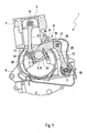
- internal combustion engine 1 is a series internal combustion engine, more precisely as a four-stroke four-cylinder in-line engine.
- the internal combustion engine 1 has a crankshaft 2 and four pistons 3 (only one shown), which are each movable in a cylinder 4 back and forth.
- the crankshaft 2 is rotatably mounted in shaft bearings (not shown) of a cylinder crankcase 5 and includes five serving for storage centric shaft journal (not visible) and four lifting or crank pin 6 (only one shown), the longitudinal center axes in different angular orientations parallel to the axis of rotation of the crankshaft 2 and are arranged in relation to this axis of rotation in different angular orientations.
- the internal combustion engine 1 further comprises an eccentric shaft 7 with a rotational axis parallel to the axis of rotation of the crankshaft 2, which is rotatably mounted next to and slightly below the crankshaft 2 in the cylinder crankcase 5, and a multi-joint crank mechanism 8 with four coupling members 9, each on one of the crank pin. 6 the crankshaft 2 are rotatably supported, wherein they are connected on one side of the crankshaft 2 by a Kolbenpleuel 10 with one of the pistons 3 and on the other side of the crankshaft 2 by a Anschpleuel 12 with the eccentric shaft 7.
- Each coupling member 9 comprises a shorter lifting arm 13, which is connected via a pivot joint 14 pivotally connected to a lower end of one of Kolbenpleuel 10. An upper end of the respective Kolbenpleuels 10 is articulated via a further pivot joint 15 on the associated piston 3. Overall, therefore, each of the four pistons 3 is connected by the respective Kolbenpleuel 10 and the respective coupling member 9 with the crankshaft 2.
- each coupling member 9 comprises a longer coupling arm 16, which is connected via a pivot joint 17 pivotally connected to an upper end of one of the Anlenkpleuel 12.
- a lower end of the respective Anlenkpleuels 12 is articulated via a further pivot joint 18 on the eccentric shaft 7.
- the Anschpleuel 12 are aligned approximately parallel to the Kolbenpleueln 10 and arranged in the axial direction of the crankshaft 2 and the eccentric shaft 7 in each case approximately in the same plane as the associated Kolbenpleuel 10.
- the compression ratio of the internal combustion engine 1 can be changed and the inclination of the piston connecting rods 10 with respect to the cylinder axis of the associated cylinders 4 can be reduced during the rotation of the crankshaft 2, resulting in a reduction of the piston side forces and thus the frictional forces between the piston 3 and cylinder walls of the cylinder 4.
- each coupling member 9 a first eye 19, a second eye 20 and a third eye 21 on.
- the first eye 19 extends through two fork legs 22 of the lifting arm 13 and, together with an associated bearing pin 23, the pivot joint 14 for the lower end of the Kolbenpleuels 10.
- the second eye 20 extends through two fork legs 24 of the coupling arm 16 and forms together with a
- the third eye 21 is disposed between the first and second eyes 19 and 20, has a larger diameter and serves to receive a crank pin 6.
- the third eye 21 is a split eye.
- the coupling member 9 consists of a coupling lever 26 and a bearing cap 27, which are connected by two screws 28, 29 on both sides of the eye 21 firmly together. How best in Fig. 4 shown, the two screws 28, 29 as well as the associated internal thread or screw holes 30, 31 in the coupling lever 12 and through holes (not visible) in the bearing cap 27 parallel longitudinal central axes 32, 33.
- the first screw 28 on the side of the first eye 19 is a short M9 screw, while the second screw 29 on the side of the second eye 20 is a longer M11 screw. Both screws 28, 29 are designed as expansion screws, so that they can withstand better bending loads.
- the coupling lever 26 and the bearing cap 27 each extend through 180 degrees around the outer circumference of the eye 21 and have on the outer circumference of the eye 21 two pairs of opposing planar contact surfaces 34, 35.
- the pairwise opposite abutment surfaces 34, 35 of the coupling lever 26 and of the bearing cap 27 on both sides directly adjoining the outer circumference of the third eye 21 of the third eye 21 to the longitudinal center axes 32, 33 of the two screws 28, 29 are perpendicular.
- the dividing plane T is inclined at an acute angle ⁇ of about 5 degrees with respect to a plane E perpendicular to the longitudinal center axes 32, 33 of the screws 28, 29 through the center 36 of the third eye 21.
- the longitudinal center axes 32, 33 of the screws 28, 29 are not aligned perpendicular to the parting plane T.
- the direction of the inclination of the parting plane T is selected so that it has on the side of the first eye 19 a greater distance than the plane E from the center of the first eye 19.
- the screw hole 30 can be formed as a through hole, which opens into the space between the two fork legs 22 of the lifting arm 13.
- the coupling lever 26 and the bearing cap 27 are on both sides of the eye 21 positively against each other.
- the coupling lever 26 is about the mouth of the screw hole 30 of the first screw 28 around with a first toothing 37 and around the mouth of the screw hole 31 of the second screw 29 around with a second toothing 38 provided.
- the first and second teeth 37, 38 each form-fitting with an opposite complementary first and second teeth 37, 38 of the bearing cap 27 in tooth engagement, as best in Fig. 3 shown.
- the two contact surfaces 34, 35 each form an adjacent to the eye 21 part of these teeth 37, 38th
- connection between the coupling lever 26 and the bearing cap 27 by two positive teeth 37, 38 allow the use of a high-strength and thus not crackable tempering steel, with which in comparison to a crackable version of the coupling member 9 also a mass reduction is possible.
- the tips of the teeth of the first toothing 37 of the coupling lever 26 a first division plane 39 and the tips of the teeth of the second toothing 38 of the coupling lever 26, a second graduation plane 40 on.
- the two graduation levels 39, 40 include different inclination angles ⁇ both with the separation plane T and with the plane E. While the inclination angle ⁇ 1 between the first dividing plane 39 and the plane E is 20 degrees, the inclination angle ⁇ 2 between the second dividing plane 40 and the plane E is smaller and is only 15 degrees. This allows the in Fig.
- the first graduation plane 39 extends through the center 36 of the third eye 21 or through the center axis of the crank pin 6 mounted in the third eye 21.
- the second graduation plane 40 or its extension extends approximately through the center of the first eye 19 and has a lateral offset relative to the center 36 of the third eye 21.
- the two graduation levels 39, 40 intersect within the third eye 21, but not in the middle between the two screws 28, 29, but closer to the second screw 29, wherein the distance of the Thomaspunks from the longitudinal central axis 32 of the first screw 28 the 3 to 4 times the distance from the longitudinal center axis 33 of the second screw 29 is.
Description
Die Erfindung betrifft ein Koppelglied für einen Mehrgelenkskurbeltrieb einer Brennkraftmaschine, mit einem Koppelglied, das einen Koppelhebel und einen Lagerdeckel umfasst, wobei der Koppelhebel ein erstes Auge für einen Kolbenpleuel des Kurbeltriebs, ein zweites Auge für einen Anlenkpleuel des Kurbeltriebs und gemeinsam mit dem Lagerdeckel ein drittes Auge für einen Kurbelzapfen einer Kurbelwelle umgibt, wobei der Koppelhebel und der Lagerdeckel am äußeren Umfang des dritten Auges in einer durch die Mitte des dritten Auges verlaufenden Trennebene aneinander stoßen und durch zwei Schrauben miteinander verschraubt sind, und wobei die beiden Schrauben parallele Längsmittelachsen aufweisen. Die Erfindung betrifft weiter einen Mehrgelenkskurbeltrieb einer Brennkraftmaschine mit einer Mehrzahl von derartigen Koppelgliedern.The invention relates to a coupling member for a multi-joint crank drive of an internal combustion engine, comprising a coupling member comprising a coupling lever and a bearing cap, wherein the coupling lever a first eye for a piston connecting rod of the crank mechanism, a second eye for a Anlenkpleuel the crank mechanism and a third together with the bearing cap Eye for a crank pin of a crankshaft surrounds, wherein the coupling lever and the bearing cap on the outer circumference of the third eye in a passing through the center of the third eye separation plane abut each other and are screwed together by two screws, and wherein the two screws have parallel longitudinal central axes. The invention further relates to a multi-joint crank drive of an internal combustion engine having a plurality of such coupling members.
Koppelglieder der eingangs genannten Art werden in Mehrgelenkskurbeltrieben von Brennkraftmaschinen als Verbindungsglieder zwischen den mit den Kolben verbundenen Kolbenpleueln, den zugehörigen Kurbelzapfen der Kurbelwelle und zugehörigen, mit einer Exzenterwelle verbundenen Anlenkpleueln eingesetzt. Mittels des Mehrgelenkskurbeltriebs kann der Arbeitshub der Kolben der Brennkraftmaschine verstellt werden, so dass sich in unterschiedlichen Arbeitstakten der Brennkraftmaschine unterschiedliche Arbeitshübe des Kolbens ergeben. Unter dem Arbeitshub ist dabei die Entfernung zu verstehen, welche zwischen einem oberen und einem unteren Totpunkt des Kolbens liegt, also mithin der von dem Kolben während des Arbeitstakts maximal zurückgelegte Weg. Alternativ oder zusätzlich kann mittels des Mehrgelenkskurbeltriebs auch das Verdichtungsverhältnis eingestellt werden, das in dem zum Kolben zugehörigen Zylinder erreicht wird, insbesondere in Abhängigkeit von dem Betriebspunkt der Brennkraftmaschine und/oder dem Arbeitstakt des Zylinders.Coupling members of the type mentioned are used in multi-joint crank drives of internal combustion engines as connecting links between the Kolbenpleueln associated with the piston, the associated crank pin of the crankshaft and associated, connected to an eccentric Anlenkpleueln. By means of the multi-joint crank drive, the working stroke of the pistons of the internal combustion engine can be adjusted so that different working strokes of the piston result in different operating strokes of the internal combustion engine. The working stroke is to be understood as meaning the distance which lies between an upper and a lower dead center of the piston, that is to say the maximum distance traveled by the piston during the working cycle. Alternatively or additionally, by means of the multi-joint crank drive and the compression ratio can be adjusted, which is achieved in the cylinder associated with the piston, in particular in dependence on the operating point of the internal combustion engine and / or the working stroke of the cylinder.
Ein Koppelglied und ein Mehrgelenkskurbeltrieb sind bereits aus der
Aus dem Stand der Technik sind weiterhin die Druckschriften
Es hat sich gezeigt, dass sich Mehrgelenkskurbeltriebe mit Koppelgliedern, bei denen der Koppelhebel und der Lagerdeckel durch derartige "windschiefe" Schrauben miteinander verbunden sind, in einer Großserienfertigung nicht mit den erforderlichen Schraubenanzugs- und Überwachungsverfahren realisieren lassen.It has been found that multi-link crank drives with coupling links, in which the coupling lever and the bearing cap are connected to one another by such "skewed" screws, can not be realized in a large-scale production with the required screw tightening and monitoring methods.
Daher wird nach Lösungen gesucht, mit denen bei Koppelgliedern, deren Schrauben parallele Längsmittelachsen aufweisen, trotz geringer Koppelgliedmasse ebenfalls eine hohe Festigkeit erzielt werden kann. Dies stößt vor allem dann auf Schwierigkeiten, wenn der Abstand zwischen dem dritten Auge und dem ersten Auge so klein wie möglich gehalten und daher die Schraubenbohrung für die auf der Seite des ersten Auges angeordnete Schraube nicht mehr wie bei dem Koppelglied aus der
Ausgehend hiervon liegt der Erfindung die Aufgabe zugrunde, ein Koppelglied und einen Mehrgelenkskurbeltrieb der eingangs genannten Art dahingehend zu verbessern, dass sich ohne "windschiefe" Schrauben zwischen dem Koppelhebel und dem Lagerdeckel bei geringer Masse des Koppelglieds eine hohe Festigkeit erzielen lässt.Proceeding from this, the present invention seeks to improve a coupling member and a multi-joint crank mechanism of the type mentioned in that can achieve a high strength without "skewed" screws between the coupling lever and the bearing cap with low mass of the coupling member.
Dies wird erfindungsgemäß dadurch erreicht, dass die Trennebene in Bezug zu einer durch die Mitte des Auges verlaufenden und zu den Längsmittelachsen der beiden Schrauben senkrechten Ebene unter einem spitzen Winkel geneigt ist, wobei an den äußeren Umfang des dritten Auges unmittelbar angrenzende paarweise gegenüberliegende Anlageflächen des Koppelhebels und des Lagerdeckels beiderseits des dritten Auges zu den Längsmittelachsen der beiden Schrauben senkrecht sind. Dies bedeutet zugleich, dass die Längsmittelachsen beider Schrauben nicht senkrecht zu der Trennebene sind.This is inventively achieved in that the parting plane is inclined at an acute angle with respect to a plane passing through the center of the eye and perpendicular to the longitudinal central axes of the two screws, wherein on the outer circumference of the third eye directly adjacent pairs of opposing contact surfaces of the coupling lever and the bearing cap on both sides of the third eye to the longitudinal center axes of the two screws are perpendicular. This means at the same time that the longitudinal center axes of both screws are not perpendicular to the parting plane.
Wenn die Trennebene auf der Seite des ersten Auges in einer Richtung vom ersten Auge weg geneigt ist, kann durch das erfindungsgemäße Merkmal der Koppelhebel auf der Seite des ersten Auges um die Schraubenbohrung herum um einige Millimeter verstärkt und damit die Schraubenbohrung um einige Millimeter vertieft oder verlängert werden. Dies gestattet es, die Schraubenbohrung auf der Seite des ersten Auges nicht wie bei dem Koppelglied aus der
Weiter kann gemäß einer bevorzugten Ausgestaltung der Erfindung anders als bei dem Koppelglied aus der
Bei einem als Gabelarm ausgebildeten Hubarm kann die Schraubenbohrung des Koppelhebels auf der Seite des ersten Auges zweckmäßig als Durchgangsbohrung ausgebildet werden, die zwischen zwei Schenkeln des Gabelarms mündet und eine der beiden Schrauben aufnimmt. Diese Schraube auf der Seite des ersten Auges wird nachfolgend auch als erste Schraube bezeichnet wird, während die Schraube auf der Seite des zweiten Auges nachfolgend auch als zweite Schraube bezeichnet wird.When designed as a fork arm lift arm, the screw hole of the coupling lever on the side of the first eye can be conveniently formed as a through hole, which opens between two legs of the fork arm and receives one of the two screws. This screw on the side of the first eye is also referred to below as the first screw, while the screw on the side of the second eye is also referred to below as the second screw.
Um trotz der Neigung der Trennebene in Bezug zu der zu den Längsmittelachsen beider Schrauben senkrechten Ebene durch die Mitte des dritten Auges das Fügen des Koppelhebels und des Lagerdeckels bei der Montage des Koppelglieds zu erleichtern, weisen der Koppelhebel und der Lagerdeckel beiderseits des dritten Auges unmittelbar angrenzend an dessen äußeren Umfang gegenüberliegende Anlageflächen auf, die gemäß einer weiteren bevorzugten Ausgestaltung der Erfindung senkrecht zu den Längsmittelachsen der beiden Schrauben sind.In order to facilitate the joining of the coupling lever and the bearing cap during assembly of the coupling member despite the inclination of the parting plane with respect to the plane perpendicular to the longitudinal center axes of both screws through the center of the third eye, the coupling lever and the bearing cap on both sides of the third eye immediately adjacent on the outer circumference opposite bearing surfaces, which are perpendicular to the longitudinal center axes of the two screws according to a further preferred embodiment of the invention.
Wie bei dem Koppelglied aus der
Wie bei dem Koppelglied aus der
Die beiden komplementären Verzahnungen erstrecken sich jeweils entlang einer Teilungsebene, die durch die Spitzen der Zähne der Verzahnung des Koppelhebels definiert wird. Wie bei dem Koppelglied aus der
Anders als bei dem Koppelglied aus der
Auf diese Weise kann der letzte Zahn der zweiten Verzahnung an dem vom dritten Auge abgewandten Ende der zweiten Verzahnung weiter von einer Oberseite des Koppelhebels weg nach unten verlegt und dadurch in diesem Bereich die Höhe des Biegequerschnitts und damit die Biegefestigkeit des Koppelhebels vergrößert werden. Dies ist vor allem deshalb von Vorteil, weil die Höhe des Biegequerschnitts auf der Seite des zweiten Auges zu Gunsten eines höheren Querschnitts auf der Seite der ersten Auges verringert wird, wenn die Trennebene zur Verlängerung der Schraubenbohrung der ersten Schraube in Bezug zu der zu den Längsmittelachsen beider Schrauben senkrechten Ebene durch die Mitte des dritten Auges geneigt worden ist, wie zuvor beschrieben.In this way, the last tooth of the second toothing at the end facing away from the third eye end of the second toothing further moved away from an upper side of the coupling lever down and thereby in this area the height of the bending cross-section and thus the flexural strength of the coupling lever can be increased. This is particularly advantageous because the height of the bending cross section on the side of the second eye is reduced in favor of a higher cross section on the side of the first eye when the parting plane for extending the screw hole of the first screw with respect to the plane perpendicular to the longitudinal center axes of both screws, has been inclined through the center of the third eye, as previously described.
Vorteilhaft ist ein erster Winkel zwischen der Teilungsebene der ersten Verzahnung und der zu den Längsmittelachsen der beiden Schrauben senkrechten Ebene durch die Mitte des dritten Auges kleiner als ein zweiter Winkel zwischen dieser Ebene und der Teilungsebene der zweiten Verzahnung, wobei der erste Winkel zweckmäßig etwa 15 Grad und der zweite Winkel zweckmäßig etwa 20 Grad beträgt. Auf diese Weise kann ein guter Kompromiss zwischen einer ausreichenden Höhe des Biegequerschnitts auf der Seite des zweiten Auges einerseits und einer ausreichenden Länge der Schraubenbohrung auf der Seite des ersten Auges andererseits erzielt werden.Advantageously, a first angle between the dividing plane of the first toothing and the plane perpendicular to the longitudinal central axes of the two screws through the center of the third eye is smaller than a second angle between this plane and the dividing plane of the second toothing, the first angle being suitably about 15 degrees and the second angle is suitably about 20 degrees. In this way, a good compromise can be achieved between a sufficient height of the bending section on the side of the second eye on the one hand and a sufficient length of the screw hole on the side of the first eye on the other hand.
Während die erste Teilungsebene zweckmäßig etwa durch die Mitte des dritten Auges verläuft, weist die zweite Teilungsebene zweckmäßig einen seitlichen Versatz gegenüber der Mitte des dritten Auges auf und verläuft zweckmäßig durch das erste Auge, vorteilhaft etwa durch dessen Mitte.While the first dividing plane expediently extends approximately through the middle of the third eye, the second dividing plane expediently has a lateral offset relative to the middle of the third eye and expediently runs through the first eye, advantageously approximately through its middle.
Wie bei dem Koppelglied aus der
Die Erfindung wird nachfolgend anhand eines in der Zeichnung dargestellten Ausführungsbeispiels näher erläutert, ohne dass eine Beschränkung der Erfindung erfolgt. Dabei zeigen:
-
Fig. 1 eine schematische Schnittansicht von Teilen einer Brennkraftmaschine mit einem Mehrgelenkskurbeltrieb; -
Fig. 2 eine perspektivische Ansicht eines Koppelglieds und eines Kolbenpleuels des Mehrgelenkskurbeltriebs; -
Fig. 3 eine Seitenansicht des Koppelglieds mit einem Koppelhebel und einem Deckelteil; -
Fig. 4 eine teilweise geschnittene Seitenansicht des Koppelhebels.
-
Fig. 1 a schematic sectional view of parts of an internal combustion engine with a multi-joint crank drive; -
Fig. 2 a perspective view of a coupling member and a piston rod of the multi-joint crank drive; -
Fig. 3 a side view of the coupling member with a coupling lever and a cover part; -
Fig. 4 a partially sectioned side view of the coupling lever.
Bei der in
Jedes Koppelglied 9 umfasst einen kürzeren Hubarm 13, der über ein Schwenkgelenk 14 schwenkbar mit einem unteren Ende von einem der Kolbenpleuel 10 verbunden ist. Ein oberes Ende des jeweiligen Kolbenpleuels 10 ist über ein weiteres Schwenkgelenk 15 am zugehörigen Kolben 3 angelenkt. Insgesamt ist also jeder der vier Kolben 3 durch den jeweiligen Kolbenpleuel 10 und das jeweilige Koppelglied 9 mit der Kurbelwelle 2 verbunden.Each
Weiter umfasst jedes Koppelglied 9 einen längeren Koppelarm 16, der über ein Schwenkgelenk 17 schwenkbar mit einem oberen Ende von einem der Anlenkpleuel 12 verbunden ist. Ein unteres Ende des jeweiligen Anlenkpleuels 12 ist über ein weiteres Schwenkgelenk 18 an der Exzenterwelle 7 angelenkt.Further, each
Die Anlenkpleuel 12 sind ungefähr parallel zu den Kolbenpleueln 10 ausgerichtet und in axialer Richtung der Kurbelwelle 2 und der Exzenterwelle 7 jeweils in etwa derselben Ebene wie der dazugehörige Kolbenpleuel 10 angeordnet.The Anlenkpleuel 12 are aligned approximately parallel to the Kolbenpleueln 10 and arranged in the axial direction of the crankshaft 2 and the
Mittels des Mehrgelenkskurbeltriebs 8 kann das Verdichtungsverhältnis der Brennkraftmaschine 1 verändert und die Neigung der Kolbenpleuel 10 in Bezug zur Zylinderachse der zugehörigen Zylinder 4 während der Drehung der Kurbelwelle 2 verringert werden, was zu einer Verringerung der Kolbenseitenkräfte und damit der Reibkräfte zwischen den Kolben 3 und Zylinderwänden der Zylinder 4 führt.By means of the
Wie am besten in
Damit sich das Koppelglied 9 auf dem Kurbelzapfen 6 anbringen lässt, ist das dritte Auge 21 ein geteiltes Auge. Zu diesem Zweck besteht das Koppelglied 9 aus einem Koppelhebel 26 und einem Lagerdeckel 27, die durch zwei Schrauben 28, 29 beiderseits des Auges 21 fest miteinander verbunden sind. Wie am besten in
Bei der ersten Schraube 28 auf der Seite des ersten Auges 19 handelt es sich um eine kurze M9-Schraube, während es sich bei der zweiten Schraube 29 auf der Seite des zweiten Auges 20 um eine längere M11 Schraube handelt. Beide Schrauben 28, 29 sind als Dehnschaftschrauben ausgeführt, so dass sie Biegebelastungen besser aushalten können.The
Der Koppelhebel 26 und der Lagerdeckel 27 erstrecken sich jeweils um 180 Grad um den äußeren Umfang des Auges 21 herum und weisen am äußeren Umfang des Auges 21 zwei Paare von gegenüberliegenden ebenen Anlageflächen 34, 35 auf. Die unmittelbar an den äußeren Umfang des Auges 21 angrenzenden inneren Enden der Anlageflächen 34, 35 spannen in der dargestellten Ausführungsform eine Trennebene T auf, die durch die Mitte 36 des Auges 21 bzw. durch die Mittelachse des im Auge 21 gelagerten Kurbelzapfens 6 verläuft. Erfindungsgemäß ist es dagegen vorgesehen, dass die an den äußeren Umfang des dritten Auges 21 unmittelbar angrenzenden paarweise gegenüberliegenden Anlageflächen 34, 35 des Koppelhebel 26 und des Lagerdeckels 27 beiderseits des dritten Auges 21 zu den Längsmittelachsen 32, 33 der beiden Schrauben 28, 29 senkrecht sind.The
Wie am besten in
Dadurch ist es anders als bei dem Koppelglied aus der
Wie aus
Wie aus einem Vergleich mit dem Koppelglied aus der
Der Koppelhebel 26 und der Lagerdeckel 27 liegen beiderseits vom Auge 21 formschlüssig gegeneinander an. Dazu ist der Koppelhebel 26 um die Mündung der Schraubenbohrung 30 der ersten Schraube 28 herum mit einer ersten Verzahnung 37 und um die Mündung der Schraubenbohrung 31 der zweiten Schraube 29 herum mit einer zweiten Verzahnung 38 versehen. Nach der Montage des Koppelgliedes 10 stehen die erste und zweite Verzahnung 37, 38 jeweils formschlüssig mit einer gegenüberliegenden komplementären ersten bzw. zweiten Verzahnung 37, 38 des Lagerdeckels 27 im Zahneingriff, wie am besten in
Die Verbindung zwischen dem Koppelhebel 26 und dem Lagerdeckel 27 durch zwei formschlüssige Verzahnungen 37, 38 ermöglichen den Einsatz eines hochfesten und damit nicht crackbaren Vergütungsstahls, mit dem im Vergleich zu einer crackbaren Ausführung des Koppelglieds 9 ebenfalls eine Massenreduzierung möglich ist.The connection between the
Wie am besten in
Wie am besten in
Wie bei dem Koppelglied aus der
Claims (11)
- Coupling element (9) for a multi-joint crank drive (8) of an internal combustion engine (1), with a coupling lever (26) and a bearing cover (27), wherein the coupling lever (26) has a first eye (19) for a piston connecting rod (10) of the crank drive (8), a second eye (20) for an articulation connecting rod (12) of the crank drive (8), and together with the bearing cover (27) surrounds a third eye (21) for a crank pin (6) of a crank shaft (2), wherein the coupling lever (26) and the bearing cover (27) abut each other at an outer periphery of the third eye (21) on a separating plane (T) which extends through the centre (36) of the third eye (21) and are screwed to one another by means of two bolts (28, 29), characterised in that the two bolts (28, 29) have parallel longitudinal central axes (32, 33), and the separating plane (T) is tilted at an acute angle (a) in relation to a plane (E) which extends through the centre of the eye (36) and is perpendicular to the longitudinal central axes (32, 33) of the two bolts (28, 29), wherein contact surfaces (34, 35) of the coupling lever (26) and the bearing cover (27), which are immediately adjacent to the outer periphery of the third eye (21) and are arranged in pairs opposite to each other, are on both sides of the third eye (21) perpendicular to the longitudinal central axes (32, 33) of the two bolts (28, 29).
- Coupling element according to claim 1, characterised in that the separating plane (T) is inclined on the side of the first eye (19) in a direction away from the first eye (19).
- Coupling element according to claim 1 or 2, characterised in that the longitudinal central axis (32) of the first bolt (28) which is arranged on the side of the first eye (19) extends through the first eye (19, 21).
- Coupling element according to any of the preceding claims, characterised in that a lift arm (13) of the coupling element (9) which is penetrated by the first eye (19) is configured as a fork arm with two fork limbs (22).
- Coupling element according to claim 3 or 4, characterised in that the screw hole (30) is a throughbore opening between the fork limbs (22).
- Coupling element according to any of the preceding claims, characterised in that the bolts (28, 29) are antifatigue bolts.
- Coupling element according to any of the preceding claims, characterised in that the coupling lever (26) and the bearing cover (27) form-fittingly abut each other with complementary toothed surfaces (37, 38) on both sides of the circumferential edge of the third eye (21).
- Coupling element according to claim 7, characterised in that two dividing planes (39, 40) which are spanned by the tips of the teeth of the toothed surfaces (37, 38) of the coupling lever (26) enclose differently sized angles (β1, β2) with the plane (E).
- Coupling element (9) according to claim 7 or 8, characterised in that the two tooth flanks of each tooth of the two toothed surfaces (37, 38) define different angular orientations in relation to the corresponding first or second dividing plane (39 or 40).
- Coupling element (9) according to any of claims 7 to 9, characterised in that the teeth of the two toothed surfaces (37, 38) of the coupling lever (26) are devoid from undercuts in the direction of the longitudinal central axes (32, 33) of the two bolts (28, 29).
- Multi-joint crank drive (8) of an internal combustion engine, characterised by a plurality of coupling elements (9) according to any of the preceding claims.
Applications Claiming Priority (2)
| Application Number | Priority Date | Filing Date | Title |
|---|---|---|---|
| DE102013021980.9A DE102013021980A1 (en) | 2013-12-20 | 2013-12-20 | Coupling link for a multi-link crank drive and multi-link crank drive |
| PCT/EP2014/003437 WO2015090605A1 (en) | 2013-12-20 | 2014-12-19 | Coupling element for a multi-joint crank drive and multi-joint crank drive |
Publications (2)
| Publication Number | Publication Date |
|---|---|
| EP3084171A1 EP3084171A1 (en) | 2016-10-26 |
| EP3084171B1 true EP3084171B1 (en) | 2018-06-13 |
Family
ID=52669569
Family Applications (1)
| Application Number | Title | Priority Date | Filing Date |
|---|---|---|---|
| EP14843231.3A Active EP3084171B1 (en) | 2013-12-20 | 2014-12-19 | Coupling element for a multi-joint crank drive and multi-joint crank drive |
Country Status (7)
| Country | Link |
|---|---|
| US (1) | US9995335B2 (en) |
| EP (1) | EP3084171B1 (en) |
| JP (1) | JP6141535B2 (en) |
| KR (1) | KR101759044B1 (en) |
| CN (1) | CN106062338B (en) |
| DE (1) | DE102013021980A1 (en) |
| WO (1) | WO2015090605A1 (en) |
Families Citing this family (3)
| Publication number | Priority date | Publication date | Assignee | Title |
|---|---|---|---|---|
| CN113795656B (en) * | 2018-12-30 | 2023-01-06 | 长城汽车股份有限公司 | Variable compression ratio mechanism, engine and automobile |
| CN110284966B (en) * | 2019-06-28 | 2021-04-20 | 长城汽车股份有限公司 | Lower connecting rod and engine with same |
| CN110285136A (en) * | 2019-06-28 | 2019-09-27 | 长城汽车股份有限公司 | Lower link and engine with it |
Family Cites Families (26)
| Publication number | Priority date | Publication date | Assignee | Title |
|---|---|---|---|---|
| FR1570045A (en) | 1968-04-26 | 1969-06-06 | ||
| JP3861583B2 (en) * | 2000-08-14 | 2006-12-20 | 日産自動車株式会社 | Piston crank mechanism of internal combustion engine |
| JP3882643B2 (en) | 2001-04-05 | 2007-02-21 | 日産自動車株式会社 | Variable compression ratio mechanism of internal combustion engine |
| DE10131322A1 (en) * | 2001-06-28 | 2003-01-23 | Federal Mogul Wiesbaden Gmbh | Broken bearing used in internal combustion engines comprises a bearing bracket and a bearing cap each having first arms that are shorter than second arms |
| JP4075600B2 (en) * | 2002-05-16 | 2008-04-16 | 日産自動車株式会社 | Pin connection structure |
| DE10222938A1 (en) * | 2002-05-24 | 2004-02-19 | Mahle Gmbh | Pistons for internal combustion engines |
| JP2004124775A (en) * | 2002-10-01 | 2004-04-22 | Nissan Motor Co Ltd | Variable compression ratio mechanism for internal combustion engine |
| JP2004124776A (en) * | 2002-10-01 | 2004-04-22 | Nissan Motor Co Ltd | Variable compression ratio mechanism and link parts for internal combustion engine |
| US7191741B2 (en) * | 2002-12-16 | 2007-03-20 | Nissan Motor Co., Ltd. | Pin connected link mechanism |
| JP4613607B2 (en) * | 2004-12-24 | 2011-01-19 | 日産自動車株式会社 | Lower link in piston crank mechanism of internal combustion engine |
| JP2007064013A (en) * | 2005-08-29 | 2007-03-15 | Honda Motor Co Ltd | Stroke variable engine |
| JP4779635B2 (en) * | 2005-12-20 | 2011-09-28 | 日産自動車株式会社 | Lower link in piston crank mechanism of internal combustion engine |
| JP4984574B2 (en) * | 2006-03-03 | 2012-07-25 | 日産自動車株式会社 | Crankshaft of piston crank mechanism |
| JP4730152B2 (en) * | 2006-03-15 | 2011-07-20 | 日産自動車株式会社 | Lower link in piston crank mechanism of internal combustion engine |
| JP2008138607A (en) * | 2006-12-01 | 2008-06-19 | Honda Motor Co Ltd | Stroke characteristic variable engine |
| JP4922121B2 (en) * | 2007-10-11 | 2012-04-25 | 本田技研工業株式会社 | Variable stroke engine |
| JP4922122B2 (en) * | 2007-10-11 | 2012-04-25 | 本田技研工業株式会社 | Variable stroke engine |
| JP4992770B2 (en) * | 2008-03-11 | 2012-08-08 | 日産自動車株式会社 | Lower link in piston crank mechanism of internal combustion engine |
| DE102010004578B4 (en) * | 2010-01-14 | 2019-11-07 | Audi Ag | Internal combustion engine with multi-joint crank drive and in pivot joints of the crank mechanism floating bolt |
| DE102010004589A1 (en) | 2010-01-14 | 2011-07-21 | Audi Ag, 85057 | In-line multi-crankcase combustion engine with a single balancer shaft for eradicating second-order mass forces |
| DE102010032441A1 (en) | 2010-07-28 | 2012-02-02 | Audi Ag | Internal combustion engine with multi-joint crank drive and additional masses at Anlenkpleueln the multi-joint crank drive for the eradication of free inertial forces |
| DE102010052004B4 (en) * | 2010-11-19 | 2012-06-21 | Audi Ag | Asymmetrically split plain bearing for radial bearing shell mounting |
| DE102011104531A1 (en) * | 2011-06-18 | 2012-12-20 | Audi Ag | Internal combustion engine |
| DE102011116609B4 (en) | 2011-10-21 | 2015-02-19 | Audi Ag | Multi-joint crank drive |
| DE102014002022B4 (en) * | 2014-02-14 | 2018-03-01 | Audi Ag | Multi-joint crank drive of an internal combustion engine and corresponding internal combustion engine |
| DE102014018898A1 (en) * | 2014-12-17 | 2016-06-23 | Audi Ag | Multi-joint crank drive for an internal combustion engine with an eccentric shaft actuator comprising a switchable transmission with at least two different reduction ratios |
-
2013
- 2013-12-20 DE DE102013021980.9A patent/DE102013021980A1/en not_active Withdrawn
-
2014
- 2014-12-19 WO PCT/EP2014/003437 patent/WO2015090605A1/en active Application Filing
- 2014-12-19 EP EP14843231.3A patent/EP3084171B1/en active Active
- 2014-12-19 KR KR1020167019800A patent/KR101759044B1/en active IP Right Grant
- 2014-12-19 US US15/106,022 patent/US9995335B2/en active Active
- 2014-12-19 JP JP2016541603A patent/JP6141535B2/en active Active
- 2014-12-19 CN CN201480076015.4A patent/CN106062338B/en active Active
Non-Patent Citations (1)
| Title |
|---|
| None * |
Also Published As
| Publication number | Publication date |
|---|---|
| CN106062338B (en) | 2018-09-14 |
| CN106062338A (en) | 2016-10-26 |
| EP3084171A1 (en) | 2016-10-26 |
| KR20160091438A (en) | 2016-08-02 |
| US20160319858A1 (en) | 2016-11-03 |
| DE102013021980A1 (en) | 2015-06-25 |
| JP2017501354A (en) | 2017-01-12 |
| JP6141535B2 (en) | 2017-06-07 |
| US9995335B2 (en) | 2018-06-12 |
| KR101759044B1 (en) | 2017-07-17 |
| WO2015090605A1 (en) | 2015-06-25 |
Similar Documents
| Publication | Publication Date | Title |
|---|---|---|
| EP2524127B1 (en) | Inline internal combustion engine with multiple link crank drive having a single balancer shaft to comprensate second order momentum forces | |
| DE60125431T2 (en) | Internal combustion engine with variable compression ratio | |
| EP2426336B1 (en) | Piston with two pivot bearings and double crankshaft piston engine | |
| EP0809749B1 (en) | Reciprocating piston engine with adjacent cylinders in the crankshaft direction in an engine case | |
| DE102010004588B4 (en) | Internal combustion engine with extended expansion stroke and balance weights on the eccentric shaft | |
| EP3084171B1 (en) | Coupling element for a multi-joint crank drive and multi-joint crank drive | |
| EP1777422B1 (en) | Connecting rod for a twin crankshaft reciprocating engine and twin crankshaft reciprocating engine | |
| DE102010027351B4 (en) | Internal combustion engine with extended expansion stroke and torque compensation | |
| EP0815370B1 (en) | Hypocycloidal crank mechanism for piston engines, engines especially for opposed-cylinder internal combustion engines | |
| DE102012008244B4 (en) | Multi-joint crank drive of an internal combustion engine | |
| DE102012001648B4 (en) | Multi-joint crank drive of an internal combustion engine and method for assembling a multi-link crank drive | |
| DE102010004578B4 (en) | Internal combustion engine with multi-joint crank drive and in pivot joints of the crank mechanism floating bolt | |
| DE102012005118B4 (en) | Multi-joint crank drive of an internal combustion engine | |
| DE102011116609B4 (en) | Multi-joint crank drive | |
| DE102015213281A1 (en) | Eccentric lever of a device for varying the compression ratio of a cylinder unit of a reciprocating internal combustion engine | |
| DE102006036827B4 (en) | Piston-driven machine | |
| DE102013019214B3 (en) | Multi-joint crank drive of an internal combustion engine and method for operating a multi-joint crank drive | |
| DE102015103206B4 (en) | Connecting rod with an eccentric adjusting device and an internal combustion engine with an adjustable compression ratio | |
| DE102013021984B4 (en) | Internal combustion engine with a cylinder crankcase having a reinforcing element | |
| AT507015B1 (en) | INTERNAL COMBUSTION ENGINE WITH SEVERAL CYLINDERS IN ROW | |
| DE102017119463A1 (en) | Internal combustion engine with non-cylindrical support pistons | |
| DE102016124759B4 (en) | Device for changing the effective length of a connecting rod during the operation of a reciprocating piston internal combustion engine | |
| DE102014014706B3 (en) | Multi-link crank drive for an internal combustion engine with axially movable control shaft and gate-guided rotatable eccentrics on the control shaft | |
| DE102004016203A1 (en) | Low-speed marine diesel engine with two contra-rotating crankshafts driven by a single connecting rod | |
| DE202007016543U1 (en) | piston engine |
Legal Events
| Date | Code | Title | Description |
|---|---|---|---|
| PUAI | Public reference made under article 153(3) epc to a published international application that has entered the european phase |
Free format text: ORIGINAL CODE: 0009012 |
|
| 17P | Request for examination filed |
Effective date: 20160720 |
|
| AK | Designated contracting states |
Kind code of ref document: A1 Designated state(s): AL AT BE BG CH CY CZ DE DK EE ES FI FR GB GR HR HU IE IS IT LI LT LU LV MC MK MT NL NO PL PT RO RS SE SI SK SM TR |
|
| AX | Request for extension of the european patent |
Extension state: BA ME |
|
| DAX | Request for extension of the european patent (deleted) | ||
| GRAP | Despatch of communication of intention to grant a patent |
Free format text: ORIGINAL CODE: EPIDOSNIGR1 |
|
| INTG | Intention to grant announced |
Effective date: 20170622 |
|
| GRAJ | Information related to disapproval of communication of intention to grant by the applicant or resumption of examination proceedings by the epo deleted |
Free format text: ORIGINAL CODE: EPIDOSDIGR1 |
|
| GRAP | Despatch of communication of intention to grant a patent |
Free format text: ORIGINAL CODE: EPIDOSNIGR1 |
|
| INTC | Intention to grant announced (deleted) | ||
| GRAJ | Information related to disapproval of communication of intention to grant by the applicant or resumption of examination proceedings by the epo deleted |
Free format text: ORIGINAL CODE: EPIDOSDIGR1 |
|
| GRAP | Despatch of communication of intention to grant a patent |
Free format text: ORIGINAL CODE: EPIDOSNIGR1 |
|
| INTG | Intention to grant announced |
Effective date: 20171114 |
|
| INTG | Intention to grant announced |
Effective date: 20171127 |
|
| GRAJ | Information related to disapproval of communication of intention to grant by the applicant or resumption of examination proceedings by the epo deleted |
Free format text: ORIGINAL CODE: EPIDOSDIGR1 |
|
| GRAP | Despatch of communication of intention to grant a patent |
Free format text: ORIGINAL CODE: EPIDOSNIGR1 |
|
| GRAJ | Information related to disapproval of communication of intention to grant by the applicant or resumption of examination proceedings by the epo deleted |
Free format text: ORIGINAL CODE: EPIDOSDIGR1 |
|
| INTG | Intention to grant announced |
Effective date: 20180220 |
|
| INTC | Intention to grant announced (deleted) | ||
| GRAP | Despatch of communication of intention to grant a patent |
Free format text: ORIGINAL CODE: EPIDOSNIGR1 |
|
| GRAS | Grant fee paid |
Free format text: ORIGINAL CODE: EPIDOSNIGR3 |
|
| INTG | Intention to grant announced |
Effective date: 20180413 |
|
| GRAA | (expected) grant |
Free format text: ORIGINAL CODE: 0009210 |
|
| AK | Designated contracting states |
Kind code of ref document: B1 Designated state(s): AL AT BE BG CH CY CZ DE DK EE ES FI FR GB GR HR HU IE IS IT LI LT LU LV MC MK MT NL NO PL PT RO RS SE SI SK SM TR |
|
| REG | Reference to a national code |
Ref country code: GB Ref legal event code: FG4D Free format text: NOT ENGLISH |
|
| REG | Reference to a national code |
Ref country code: CH Ref legal event code: EP Ref country code: AT Ref legal event code: REF Ref document number: 1008740 Country of ref document: AT Kind code of ref document: T Effective date: 20180615 |
|
| REG | Reference to a national code |
Ref country code: IE Ref legal event code: FG4D Free format text: LANGUAGE OF EP DOCUMENT: GERMAN |
|
| REG | Reference to a national code |
Ref country code: DE Ref legal event code: R096 Ref document number: 502014008572 Country of ref document: DE |
|
| REG | Reference to a national code |
Ref country code: NL Ref legal event code: MP Effective date: 20180613 |
|
| REG | Reference to a national code |
Ref country code: LT Ref legal event code: MG4D |
|
| PG25 | Lapsed in a contracting state [announced via postgrant information from national office to epo] |
Ref country code: NO Free format text: LAPSE BECAUSE OF FAILURE TO SUBMIT A TRANSLATION OF THE DESCRIPTION OR TO PAY THE FEE WITHIN THE PRESCRIBED TIME-LIMIT Effective date: 20180913 Ref country code: FI Free format text: LAPSE BECAUSE OF FAILURE TO SUBMIT A TRANSLATION OF THE DESCRIPTION OR TO PAY THE FEE WITHIN THE PRESCRIBED TIME-LIMIT Effective date: 20180613 Ref country code: BG Free format text: LAPSE BECAUSE OF FAILURE TO SUBMIT A TRANSLATION OF THE DESCRIPTION OR TO PAY THE FEE WITHIN THE PRESCRIBED TIME-LIMIT Effective date: 20180913 Ref country code: SE Free format text: LAPSE BECAUSE OF FAILURE TO SUBMIT A TRANSLATION OF THE DESCRIPTION OR TO PAY THE FEE WITHIN THE PRESCRIBED TIME-LIMIT Effective date: 20180613 Ref country code: CY Free format text: LAPSE BECAUSE OF FAILURE TO SUBMIT A TRANSLATION OF THE DESCRIPTION OR TO PAY THE FEE WITHIN THE PRESCRIBED TIME-LIMIT Effective date: 20180613 Ref country code: ES Free format text: LAPSE BECAUSE OF FAILURE TO SUBMIT A TRANSLATION OF THE DESCRIPTION OR TO PAY THE FEE WITHIN THE PRESCRIBED TIME-LIMIT Effective date: 20180613 Ref country code: LT Free format text: LAPSE BECAUSE OF FAILURE TO SUBMIT A TRANSLATION OF THE DESCRIPTION OR TO PAY THE FEE WITHIN THE PRESCRIBED TIME-LIMIT Effective date: 20180613 |
|
| PG25 | Lapsed in a contracting state [announced via postgrant information from national office to epo] |
Ref country code: HR Free format text: LAPSE BECAUSE OF FAILURE TO SUBMIT A TRANSLATION OF THE DESCRIPTION OR TO PAY THE FEE WITHIN THE PRESCRIBED TIME-LIMIT Effective date: 20180613 Ref country code: GR Free format text: LAPSE BECAUSE OF FAILURE TO SUBMIT A TRANSLATION OF THE DESCRIPTION OR TO PAY THE FEE WITHIN THE PRESCRIBED TIME-LIMIT Effective date: 20180914 Ref country code: LV Free format text: LAPSE BECAUSE OF FAILURE TO SUBMIT A TRANSLATION OF THE DESCRIPTION OR TO PAY THE FEE WITHIN THE PRESCRIBED TIME-LIMIT Effective date: 20180613 Ref country code: RS Free format text: LAPSE BECAUSE OF FAILURE TO SUBMIT A TRANSLATION OF THE DESCRIPTION OR TO PAY THE FEE WITHIN THE PRESCRIBED TIME-LIMIT Effective date: 20180613 |
|
| PG25 | Lapsed in a contracting state [announced via postgrant information from national office to epo] |
Ref country code: NL Free format text: LAPSE BECAUSE OF FAILURE TO SUBMIT A TRANSLATION OF THE DESCRIPTION OR TO PAY THE FEE WITHIN THE PRESCRIBED TIME-LIMIT Effective date: 20180613 |
|
| PG25 | Lapsed in a contracting state [announced via postgrant information from national office to epo] |
Ref country code: SK Free format text: LAPSE BECAUSE OF FAILURE TO SUBMIT A TRANSLATION OF THE DESCRIPTION OR TO PAY THE FEE WITHIN THE PRESCRIBED TIME-LIMIT Effective date: 20180613 Ref country code: IS Free format text: LAPSE BECAUSE OF FAILURE TO SUBMIT A TRANSLATION OF THE DESCRIPTION OR TO PAY THE FEE WITHIN THE PRESCRIBED TIME-LIMIT Effective date: 20181013 Ref country code: EE Free format text: LAPSE BECAUSE OF FAILURE TO SUBMIT A TRANSLATION OF THE DESCRIPTION OR TO PAY THE FEE WITHIN THE PRESCRIBED TIME-LIMIT Effective date: 20180613 Ref country code: CZ Free format text: LAPSE BECAUSE OF FAILURE TO SUBMIT A TRANSLATION OF THE DESCRIPTION OR TO PAY THE FEE WITHIN THE PRESCRIBED TIME-LIMIT Effective date: 20180613 Ref country code: RO Free format text: LAPSE BECAUSE OF FAILURE TO SUBMIT A TRANSLATION OF THE DESCRIPTION OR TO PAY THE FEE WITHIN THE PRESCRIBED TIME-LIMIT Effective date: 20180613 Ref country code: PL Free format text: LAPSE BECAUSE OF FAILURE TO SUBMIT A TRANSLATION OF THE DESCRIPTION OR TO PAY THE FEE WITHIN THE PRESCRIBED TIME-LIMIT Effective date: 20180613 |
|
| PG25 | Lapsed in a contracting state [announced via postgrant information from national office to epo] |
Ref country code: IT Free format text: LAPSE BECAUSE OF FAILURE TO SUBMIT A TRANSLATION OF THE DESCRIPTION OR TO PAY THE FEE WITHIN THE PRESCRIBED TIME-LIMIT Effective date: 20180613 Ref country code: SM Free format text: LAPSE BECAUSE OF FAILURE TO SUBMIT A TRANSLATION OF THE DESCRIPTION OR TO PAY THE FEE WITHIN THE PRESCRIBED TIME-LIMIT Effective date: 20180613 |
|
| REG | Reference to a national code |
Ref country code: DE Ref legal event code: R097 Ref document number: 502014008572 Country of ref document: DE |
|
| PLBE | No opposition filed within time limit |
Free format text: ORIGINAL CODE: 0009261 |
|
| STAA | Information on the status of an ep patent application or granted ep patent |
Free format text: STATUS: NO OPPOSITION FILED WITHIN TIME LIMIT |
|
| 26N | No opposition filed |
Effective date: 20190314 |
|
| PG25 | Lapsed in a contracting state [announced via postgrant information from national office to epo] |
Ref country code: DK Free format text: LAPSE BECAUSE OF FAILURE TO SUBMIT A TRANSLATION OF THE DESCRIPTION OR TO PAY THE FEE WITHIN THE PRESCRIBED TIME-LIMIT Effective date: 20180613 Ref country code: SI Free format text: LAPSE BECAUSE OF FAILURE TO SUBMIT A TRANSLATION OF THE DESCRIPTION OR TO PAY THE FEE WITHIN THE PRESCRIBED TIME-LIMIT Effective date: 20180613 |
|
| REG | Reference to a national code |
Ref country code: CH Ref legal event code: PL |
|
| PG25 | Lapsed in a contracting state [announced via postgrant information from national office to epo] |
Ref country code: LU Free format text: LAPSE BECAUSE OF NON-PAYMENT OF DUE FEES Effective date: 20181219 Ref country code: MC Free format text: LAPSE BECAUSE OF FAILURE TO SUBMIT A TRANSLATION OF THE DESCRIPTION OR TO PAY THE FEE WITHIN THE PRESCRIBED TIME-LIMIT Effective date: 20180613 |
|
| REG | Reference to a national code |
Ref country code: IE Ref legal event code: MM4A |
|
| REG | Reference to a national code |
Ref country code: BE Ref legal event code: MM Effective date: 20181231 |
|
| PG25 | Lapsed in a contracting state [announced via postgrant information from national office to epo] |
Ref country code: IE Free format text: LAPSE BECAUSE OF NON-PAYMENT OF DUE FEES Effective date: 20181219 |
|
| PG25 | Lapsed in a contracting state [announced via postgrant information from national office to epo] |
Ref country code: BE Free format text: LAPSE BECAUSE OF NON-PAYMENT OF DUE FEES Effective date: 20181231 Ref country code: AL Free format text: LAPSE BECAUSE OF FAILURE TO SUBMIT A TRANSLATION OF THE DESCRIPTION OR TO PAY THE FEE WITHIN THE PRESCRIBED TIME-LIMIT Effective date: 20180613 |
|
| PG25 | Lapsed in a contracting state [announced via postgrant information from national office to epo] |
Ref country code: CH Free format text: LAPSE BECAUSE OF NON-PAYMENT OF DUE FEES Effective date: 20181231 Ref country code: LI Free format text: LAPSE BECAUSE OF NON-PAYMENT OF DUE FEES Effective date: 20181231 |
|
| PG25 | Lapsed in a contracting state [announced via postgrant information from national office to epo] |
Ref country code: MT Free format text: LAPSE BECAUSE OF FAILURE TO SUBMIT A TRANSLATION OF THE DESCRIPTION OR TO PAY THE FEE WITHIN THE PRESCRIBED TIME-LIMIT Effective date: 20180613 |
|
| PG25 | Lapsed in a contracting state [announced via postgrant information from national office to epo] |
Ref country code: TR Free format text: LAPSE BECAUSE OF FAILURE TO SUBMIT A TRANSLATION OF THE DESCRIPTION OR TO PAY THE FEE WITHIN THE PRESCRIBED TIME-LIMIT Effective date: 20180613 |
|
| PG25 | Lapsed in a contracting state [announced via postgrant information from national office to epo] |
Ref country code: PT Free format text: LAPSE BECAUSE OF FAILURE TO SUBMIT A TRANSLATION OF THE DESCRIPTION OR TO PAY THE FEE WITHIN THE PRESCRIBED TIME-LIMIT Effective date: 20180613 |
|
| PG25 | Lapsed in a contracting state [announced via postgrant information from national office to epo] |
Ref country code: MK Free format text: LAPSE BECAUSE OF NON-PAYMENT OF DUE FEES Effective date: 20180613 Ref country code: HU Free format text: LAPSE BECAUSE OF FAILURE TO SUBMIT A TRANSLATION OF THE DESCRIPTION OR TO PAY THE FEE WITHIN THE PRESCRIBED TIME-LIMIT; INVALID AB INITIO Effective date: 20141219 |
|
| REG | Reference to a national code |
Ref country code: AT Ref legal event code: MM01 Ref document number: 1008740 Country of ref document: AT Kind code of ref document: T Effective date: 20191219 |
|
| PG25 | Lapsed in a contracting state [announced via postgrant information from national office to epo] |
Ref country code: AT Free format text: LAPSE BECAUSE OF NON-PAYMENT OF DUE FEES Effective date: 20191219 |
|
| PGFP | Annual fee paid to national office [announced via postgrant information from national office to epo] |
Ref country code: GB Payment date: 20221215 Year of fee payment: 9 Ref country code: FR Payment date: 20221216 Year of fee payment: 9 Ref country code: DE Payment date: 20221231 Year of fee payment: 9 |
|
| P01 | Opt-out of the competence of the unified patent court (upc) registered |
Effective date: 20230530 |