EP0809749B1 - Reciprocating piston engine with adjacent cylinders in the crankshaft direction in an engine case - Google Patents
Reciprocating piston engine with adjacent cylinders in the crankshaft direction in an engine case Download PDFInfo
- Publication number
- EP0809749B1 EP0809749B1 EP96904775A EP96904775A EP0809749B1 EP 0809749 B1 EP0809749 B1 EP 0809749B1 EP 96904775 A EP96904775 A EP 96904775A EP 96904775 A EP96904775 A EP 96904775A EP 0809749 B1 EP0809749 B1 EP 0809749B1
- Authority
- EP
- European Patent Office
- Prior art keywords
- guide
- eccentric
- reciprocating
- disposed
- piston rods
- Prior art date
- Legal status (The legal status is an assumption and is not a legal conclusion. Google has not performed a legal analysis and makes no representation as to the accuracy of the status listed.)
- Expired - Lifetime
Links
- 238000002485 combustion reaction Methods 0.000 claims description 4
- 238000005096 rolling process Methods 0.000 claims description 4
- 230000003068 static effect Effects 0.000 claims description 2
- 230000008878 coupling Effects 0.000 description 9
- 238000010168 coupling process Methods 0.000 description 9
- 238000005859 coupling reaction Methods 0.000 description 9
- 238000004519 manufacturing process Methods 0.000 description 3
- 210000001061 forehead Anatomy 0.000 description 2
- 238000005461 lubrication Methods 0.000 description 2
- 230000005540 biological transmission Effects 0.000 description 1
- 230000015572 biosynthetic process Effects 0.000 description 1
- 238000010276 construction Methods 0.000 description 1
- 230000008030 elimination Effects 0.000 description 1
- 238000003379 elimination reaction Methods 0.000 description 1
- 239000004575 stone Substances 0.000 description 1
Images

Classifications
-
- F—MECHANICAL ENGINEERING; LIGHTING; HEATING; WEAPONS; BLASTING
- F01—MACHINES OR ENGINES IN GENERAL; ENGINE PLANTS IN GENERAL; STEAM ENGINES
- F01B—MACHINES OR ENGINES, IN GENERAL OR OF POSITIVE-DISPLACEMENT TYPE, e.g. STEAM ENGINES
- F01B9/00—Reciprocating-piston machines or engines characterised by connections between pistons and main shafts, not specific to groups F01B1/00 - F01B7/00
- F01B9/02—Reciprocating-piston machines or engines characterised by connections between pistons and main shafts, not specific to groups F01B1/00 - F01B7/00 with crankshaft
- F01B9/026—Rigid connections between piston and rod; Oscillating pistons
-
- F—MECHANICAL ENGINEERING; LIGHTING; HEATING; WEAPONS; BLASTING
- F02—COMBUSTION ENGINES; HOT-GAS OR COMBUSTION-PRODUCT ENGINE PLANTS
- F02B—INTERNAL-COMBUSTION PISTON ENGINES; COMBUSTION ENGINES IN GENERAL
- F02B75/00—Other engines
- F02B75/16—Engines characterised by number of cylinders, e.g. single-cylinder engines
- F02B75/18—Multi-cylinder engines
- F02B75/24—Multi-cylinder engines with cylinders arranged oppositely relative to main shaft and of "flat" type
- F02B75/246—Multi-cylinder engines with cylinders arranged oppositely relative to main shaft and of "flat" type with only one crankshaft of the "pancake" type, e.g. pairs of connecting rods attached to common crankshaft bearing
Definitions
- the invention is based on the preamble of claim 1 of GB-A 1,060,372.
- This document shows and describes an embodiment of a reciprocating piston machine with diametrically arranged pairs of cylinders, the parallel axes of which Cut the crankshaft axis of rotation orthogonally.
- This generic reciprocating machine is an internal combustion engine combined with a piston compressor.
- This known machine comprises a jack with a hypocycloid Straight guidance, which combined with a crankshaft and with each other rotatably connected eccentric includes.
- Both opposed in diametrical cylinders Piston rods connecting pistons stand out together with one two-part, tubular stroke eccentric in drive connection, in the a guide eccentric with one end of the machine housing on both ends rectilinearly guided guide element is arranged.
- Another disadvantage is the complex and complex structure of this jack with hypocycloidal straight line.
- DE-PS 271 755 shows and describes an embodiment of an internal combustion engine with reciprocating pistons in diametrically arranged cylinder pairs, whose parallel axes run in a transverse plane to the crankshaft axis of rotation. This The arrangement allows the for a jack with hypocycloidal straight guidance Connection of the parallel piston rods to a single guide ring stroke eccentric arranged in the middle between pinions of pairs of cardan circles.
- a hypocycloid reciprocating piston machine in the plane of the crankshaft axis of rotation in the direction of the crankshaft has adjacent pairs of cylinders, between the push rods as a hypocycloid straight line, another orthogonally arranged A pair of cylinders is provided.
- this pair of cylinders they serve in others Cylinders of the reciprocating piston machine oscillating pistons as guide elements, so that with this crosswise arrangement of pairs of cylinders a disadvantage large-scale internal combustion engine results.
- the invention is based, for a generic piston engine the task the greatest possible simplification, in particular of the lifting engine depict hypocycloidal straightness, which is also a compact design allowed at a relatively low weight.
- Piston rods for pistons in a pair of cylinders or for pistons in two The invention offers diametrically arranged cylinder pairs (4-cylinder flat engine) in an advantageous manner in addition to a space-saving arrangement of a part of the Mainly hypocycloidal straight line between the piston rods a particularly simple structure. This can be done with minimal effort of a single, interacting with guide surfaces provided on the housing Guide element reached, with which a minimum of straight guide components and guide surfaces is achieved.
- a reciprocating piston machine are diametrically arranged pairs of cylinders opposite reciprocating pistons via piston rods connected connected in the same direction, being on a crank pin of the crankshaft in the middle between the piston rods with the single guide element hypocycloidal straight guide interacting guide eccentric rotatable is arranged, which is arranged on both sides adjacent to the crank pin and stroke eccentrics that engage in the piston rods so as to rotate the straight guide is in a rotationally fixed connection.
- This 3-disc eccentric combination according to the invention points to that from the above DE-PS 271 755 known eccentric double pinion combination due to the elimination of the gears on a simpler design, which also the transmission high piston forces with safe hydrodynamic lubrication guaranteed.
- This arrangement according to the invention advantageously reduces the Free crank pin length for two pairs of pistons in synchronism to a minimum, which results from the cylinder distance plus twice the half piston rod strength results.
- the guiding element is the hypocycloid Straight guidance a Wattscher already proposed in DE-A 41 08 311 Handlebar provided
- the coupling between the piston rods on the single Guide eccentric is arranged, the swing arms in at least one in their articulation points with one relative to the coupling and / or Machine housing rotatably and fixably arranged eccentric as a means are equipped to compensate for dimensional tolerances.
- This setting eccentric will after assembling the lifting gear when the coupling is in the middle position, first in rotated one direction until resistance appeared, then in the opposite direction Direction turned to the next resistance and finally fixed between the two resistance positions.
- the machine housing encapsulated coupling of the Watts handlebars are advantageously the Articulation points of the swivel arms with adjusting eccentrics on the machine housing side equipped, for example for automatic adjustment in a Series production of the reciprocating machine are accessible.
- the guide eccentric formed from parts connectable in the axial direction of the trunnion, with support a simple construction of a stroke eccentric on each part on the piston rod side and a balancing mass related to the axis of the crankshaft crank pin is arranged.
- the guide eccentric the hypocycloidal straight guide with one between the piston rods on the machine housing side straight-line sliding guiding element combined, which, according to one embodiment, is designed with parallel guide surfaces Sliding block, in particular rolling bearing block or after one another embodiment, a roller bearing arranged on the guide eccentric can be.
- the last-mentioned embodiment is already per se, for example GB-A 1 060 372 mentioned at the outset.
- the aforementioned guide elements each act with separate guide strips together, to compensate for dimensional tolerances across the direction of guidance are arranged displaceably in / on the machine housing.
- To relocate the Guide rails are preferably arranged hydraulically in the machine housing acted upon pistons provided, which are additionally tiltable with the guide strips Connect.
- the sliding block is parallel to its guide surfaces in the guide direction divided in half so that the guide eccentric including in its two forehead areas arranged balancing masses can be formed in one piece. Is achieved thus a rigid formation of the guide eccentric described.
- Reciprocating pistons 4, 4 'and 5, 5' according to FIG. 2 are connected to one another via piston rods 6, 7 connected.
- a jack 8 for the oscillating arrangement of the piston pairs 4, 4 'and 5, 5' by means of the piston rods 6, 7 is a jack 8 with a hypocycloidal straight line 9 provided.
- a line 15 of the crankshaft 10 parallel to the crankshaft axis of rotation 1 symbolizes a crank pin.
- On this crank pin 15 are in the outer End regions that are mounted in the piston rods 6 and 7 parallel to one another Hub eccentric 13, 14 rotatably arranged. Due to the oscillating in the same direction Piston pairs 4, 4 'and 5, 5' are the stroke eccentrics 13, 14 on the common Crank pin 15 arranged in the same direction.
- This leadership eccentric 16 acts with one between the piston rods 6, 7 for reciprocating piston pairs 4, 4 'and 5, 5' of a row of adjacent cylinders 2, 3 arranged guide element 17 of the straight guide 9 together, which is transverse to the directions of movement the piston rods 6 and 7 in the substantially straight guide element 17 principally with guide surfaces arranged on the machine housing cooperates.
- the straight line is hypocycloid 9 of the lifting gear 8 combined with a Watt handlebar 18, the Coupling 19 as a guide element 17 between the piston rods 6 and 7 on the Guide eccentric 16 is arranged mounted.
- the coupling 19 is schematic shown swing arms 20 hinged to the machine housing, not shown.
- the swing arms 20 are preferably in their housing-side articulation points 21 each with a rotatable and fixable relative to the machine housing Adjusting eccentric 22 equipped as a means to compensate for dimensional tolerances.
- This setting eccentric 22 are after the assembly of the jack 8 in Machine housing, not shown, one after the other first in one direction rotated to produce a turning resistance, then in the opposite Direction turned until the next resistance and finally about fixed between the two resistance positions.
- the coupling 19 is arranged in its central position, the center of the guide eccentric 16 receiving bore 23 substantially with the crankshaft axis of rotation 1 is aligned or slightly due to dimensional tolerances is parallel spaced.
- the setting eccentrics 22 can in the lifting engine 8 existing bearing games a setting of the paddock 19 can be found, with the coupling 19 over its entire guide stroke between its extreme positions jamming in the lifting engine is safely avoided.
- Arrangement is an automatic setting of the sliding block 26 reached with its hole center relative to the crankshaft axis of rotation 1.
- the backdrop stone 26 can also with the interposition of roller bearing devices, not shown or rolling elements interact with the guide strips 27, 27 'in order to thereby alone or in connection with the displaceable guide strips 27, 27 ' a jamming or self-locking of the straight guide 9 in a TDC area Avoid the pistons 4, 4 ', 5, 5', especially during a cold start.
- a roller bearing arranged on the guide eccentric 16 is provided be that, for example, relocatable with its outer bearing ring arranged guide strips 27, 27 'is slidably connected.
Landscapes
- Engineering & Computer Science (AREA)
- Mechanical Engineering (AREA)
- General Engineering & Computer Science (AREA)
- Chemical & Material Sciences (AREA)
- Combustion & Propulsion (AREA)
- Transmission Devices (AREA)
- Reciprocating Pumps (AREA)
- Shafts, Cranks, Connecting Bars, And Related Bearings (AREA)
Description
Die Erfindung geht gemäß dem Oberbegriff des Patentanspruches 1 von der GB-A
1 060 372 aus.The invention is based on the preamble of
Dieses Dokument zeigt und beschreibt ein Ausführungsbeispiel einer Hubkolbenmaschine mit diametral angeordneten Zylinderpaaren, deren parallele Achsen die Kurbelwellen-Drehachse orthogonal schneiden. Diese gattungsgemäße Hubkolbenmaschine ist eine mit einem Kolbenkompressor kombinierte Brennkraftmaschine. Diese bekannte Maschine umfaßt ein Hubtriebwerk mit einer hypozykloidischen Geradführung, die mit einer Kurbelwelle kombinierte und miteinander drehfest verbundene Exzenter umfaßt. Beide in diametralen Zylindern gegenüberliegende Kolben verbindende Kolbenstangen stehen gemeinsam mit einem aus zwei Teilen gebauten, rohrartigen Hub-Exzenter in Antriebsverbindung, in dessen beiden Endbereichen je ein Führungs-Exzenter mit einem maschinengehäuseseitig geradlinig gleitbeweglich geführten Führungselement angeordnet ist.This document shows and describes an embodiment of a reciprocating piston machine with diametrically arranged pairs of cylinders, the parallel axes of which Cut the crankshaft axis of rotation orthogonally. This generic reciprocating machine is an internal combustion engine combined with a piston compressor. This known machine comprises a jack with a hypocycloid Straight guidance, which combined with a crankshaft and with each other rotatably connected eccentric includes. Both opposed in diametrical cylinders Piston rods connecting pistons stand out together with one two-part, tubular stroke eccentric in drive connection, in the a guide eccentric with one end of the machine housing on both ends rectilinearly guided guide element is arranged.
Besonders nachteilig an diesem bekannten Hubtriebwerk sind zusätzlich der Geradführung der Hubkolben dienende, zu diesen koaxial im Maschinengehäuse geführt angeordnete Zylinderrohre, die zur schiebebeweglichen Führung ebenfalls mit dem rohrartigen Hub-Exzenter in Antriebsverbindung stehen. Diese Anordnung bedingt eine in Längsrichtung der Kurbelwelle langbauende Hubkolbenmaschine mit nachteilig großen Lagerabständen für die Kurbelwelle im Maschinengehäuse. Particularly disadvantageous of this known lifting engine are the Straight guide of the reciprocating pistons, coaxial to these in the machine housing guided cylinder tubes, also for sliding movement guidance are in drive connection with the tubular stroke eccentric. This arrangement requires a reciprocating piston machine that is long in the longitudinal direction of the crankshaft with disadvantageously large bearing distances for the crankshaft in the machine housing.
Weiter nachteilig ist der aufwendige und komplizierte Aufbau dieses Hubtriebwerkes mit hypozykloidischer Geradführung.Another disadvantage is the complex and complex structure of this jack with hypocycloidal straight line.
Die DE-PS 271 755 zeigt und beschreibt ein Ausführungsbeispiel einer Brennkraftmaschine mit Hubkolben in diametral angeordneten Zylinderpaaren, deren parallele Achsen in einer Querebene zur Kurbelwellen-Drehachse verlaufen. Diese Anordnung erlaubt bei einem Hubtriebwerk mit hypozykloidischer Geradführung die Anbindung der parallelen Kolbenstangen an einen einzigen Führungsring eines mittig zwischen Ritzeln von Kardankreispaaren drehfest angeordneten Hub-Exzenters.DE-PS 271 755 shows and describes an embodiment of an internal combustion engine with reciprocating pistons in diametrically arranged cylinder pairs, whose parallel axes run in a transverse plane to the crankshaft axis of rotation. This The arrangement allows the for a jack with hypocycloidal straight guidance Connection of the parallel piston rods to a single guide ring stroke eccentric arranged in the middle between pinions of pairs of cardan circles.
Im Gegensatz zum eingangs beschriebenen Stand der Technik ergibt sich mit dieser bekannten Anordnung mit hypozykloidischer Geradführung zwar eine in Längsrichtung der Kurbelwelle kurzbauende Hubkolbenmaschine mit relativ kurzen Lagerabständen der Kurbelwelle, nachteilig hierbei ist jedoch die geringe Festigkeit dieses Hubtriebwerkes mit seiner Verzahnung.In contrast to the prior art described at the outset, this results in known arrangement with hypocycloidal straight line guidance in Longitudinal direction of the crankshaft short piston engine with relatively short Bearing distances of the crankshaft, however, the disadvantage is the low strength this jack with its teeth.
Weiter ist aus der DE-A 25 19 908 eine Hypozykloiden-Hubkolbenmaschine bekannt, die in der Ebene der Kurbelwellen-Drehachse in Richtung der Kurbelwelle benachbart angeordnete Zylinderpaare aufweist, zwischen deren Schubstangen als hypozykloidische Geradführung ein weiteres, orthogonal gerichtet angeordnetes Zylinderpaar vorgesehen ist. Bei diesem Zylinderpaar dienen deren in weiteren Zylindern der Hubkolbenmaschine oszillierende Kolben als Führungselemente, so daß sich mit dieser kreuzweisen Anordnung von Zylinderpaaren eine nachteilig großbauende Brennkraftmaschine ergibt.Furthermore, a hypocycloid reciprocating piston machine is known from DE-A 25 19 908, in the plane of the crankshaft axis of rotation in the direction of the crankshaft has adjacent pairs of cylinders, between the push rods as a hypocycloid straight line, another orthogonally arranged A pair of cylinders is provided. In this pair of cylinders, they serve in others Cylinders of the reciprocating piston machine oscillating pistons as guide elements, so that with this crosswise arrangement of pairs of cylinders a disadvantage large-scale internal combustion engine results.
Der Erfindung liegt die Aufgabe zugrunde, für eine gattungsgemäße Hubkolbenmaschine eine größtmögliche Vereinfachung insbesondere des Hubtriebwerkes mit hypozykloidischer Geradführung darzustellen, die zudem eine kompakte Bauweise bei relativ geringem Gewicht erlaubt.The invention is based, for a generic piston engine the task the greatest possible simplification, in particular of the lifting engine depict hypocycloidal straightness, which is also a compact design allowed at a relatively low weight.
Diese Aufgabe ist mit dem Patentanspruch 1 gelöst, wobei auf einem zwischen
den Kolbenstangen für Hubkolben von in Reihe benachbarter Zylinder angeordneten
Führungsexzenter ein einziges Führungselement der Geradführung der beiden
Kolbenstangen dient. This object is achieved with
Für Hubkolbenmaschinen mit in einer Ebene der Kurbelwellen-Drehachse oszillierenden Kolbenstangen für Kolben eines Zylinderpaares oder für Kolben zweier diametral angeordneter Zylinderpaare (4-Zylinder-Flachmotor) bietet die Erfindung in vorteilhafter Weise neben einer platzsparenden Anordnung eines Teiles der hypozykloidischen Geradführung zwischen den Kolbenstangen damit vor allem einen besonders einfachen Aufbau. Dieser ist mit geringstem Aufwand mittels eines einzigen, mit gehäuseseitig vorgesehenen Führungsflächen zusammenwirkenden Führungselementes erreicht, womit ein Minimum an Geradführungs-Bauteilen und Führungsflächen erzielt ist.For reciprocating engines with oscillating in one plane of the crankshaft axis of rotation Piston rods for pistons in a pair of cylinders or for pistons in two The invention offers diametrically arranged cylinder pairs (4-cylinder flat engine) in an advantageous manner in addition to a space-saving arrangement of a part of the Mainly hypocycloidal straight line between the piston rods a particularly simple structure. This can be done with minimal effort of a single, interacting with guide surfaces provided on the housing Guide element reached, with which a minimum of straight guide components and guide surfaces is achieved.
Mit einem nach einer bevorzugten Ausgestaltung vorgesehenen einzigen, quer zu den oszillierenden Kolbenstangen zwischen diesen beweglich angeordnetem Führungselement ist die Anzahl an Bauteil-Toleranzen vorteilhaft vermindert. Weiter kann die erfindungsgemäße Geradführung mit Mitteln zum statischen und/oder dynamischen Ausgleich von Maßtoleranzen zwischen Maschinengehäuse und Hubtriebwerk ausgerüstet sein. Damit kann eine von der Kurbelwellen-Drehachse abweichende Lage der Geradführung für das Führungselement vorteilhaft ausgeglichen werden. Hohe Fertigungskosten durch extreme Fertigungsgenauigkeiten sind damit vermieden.With a single provided according to a preferred embodiment, across the oscillating piston rods between these movably arranged guide element the number of component tolerances is advantageously reduced. Further can the linear guidance according to the invention with means for static and / or dynamic compensation of dimensional tolerances between machine housing and Lift engine to be equipped. This allows one of the crankshaft's axis of rotation deviating position of the straight guide advantageously compensated for the guide element become. High manufacturing costs due to extreme manufacturing accuracy are avoided.
In einer bevorzugten Ausgestaltung einer Hubkolbenmaschine sind in diametral angeordneten Zylinderpaaren gegenüberliegende Hubkolben über Kolbenstangen gleichsinnig angetrieben verbunden, wobei auf einem Hubzapfen der Kurbelwelle mittig zwischen den Kolbenstangen ein mit dem einzigen Führungselement der hypozykloidischen Geradführung zusammenwirkender Führungs-Exzenter drehbeweglich angeordnet ist, der mit beiderseits benachbart auf dem Hubzapfen angeordneten und in die Kolbenstangen drehbeweglich eingreifenden Hub-Exzentern der Geradführung in drehfester Verbindung steht. Diese erfindungsgemäße 3-Scheiben-Exzenter-Kombination weist gegenüber der aus der eingangs erwähnten DE-PS 271 755 bekannten Exzenter-Doppelritzel-Kombination durch den Fortfall der Verzahnungen eine einfachere Ausgestaltung auf, die zusätzlich die Übertragung hoher Kolbenkräfte bei sicherer hydrodynamischer Schmierung gewährleistet. In a preferred embodiment of a reciprocating piston machine are diametrically arranged pairs of cylinders opposite reciprocating pistons via piston rods connected connected in the same direction, being on a crank pin of the crankshaft in the middle between the piston rods with the single guide element hypocycloidal straight guide interacting guide eccentric rotatable is arranged, which is arranged on both sides adjacent to the crank pin and stroke eccentrics that engage in the piston rods so as to rotate the straight guide is in a rotationally fixed connection. This 3-disc eccentric combination according to the invention points to that from the above DE-PS 271 755 known eccentric double pinion combination due to the elimination of the gears on a simpler design, which also the transmission high piston forces with safe hydrodynamic lubrication guaranteed.
Diese erfindungsgemäße Anordnung reduziert in weiterer vorteilhafter Weise die freie Hubzapfenlänge der Kurbelwelle für zwei im Gleichlauf vorgesehene Kolbenpaare auf ein Mindestmaß, das sich aus dem Zylinderabstand plus zweimal der halben Kolbenstangenstärke ergibt. Damit können die Wangen der Kurbelwelle eng benachbart der jeweiligen Kolbenstange angeordnet und mit auf die Kurbelwellen-Drehachse bezogenen Ausgleichsmassen für die Hubkolben und Kolbenstange ausgerüstet werden ähnlich der günstigen, aus der vorerwähnten DE-PS 271 755 bekannten Ausgestaltung.This arrangement according to the invention advantageously reduces the Free crank pin length for two pairs of pistons in synchronism to a minimum, which results from the cylinder distance plus twice the half piston rod strength results. This allows the cheeks of the crankshaft arranged closely adjacent to the respective piston rod and on the crankshaft axis of rotation compensating masses for the reciprocating piston and piston rod be equipped similar to the cheap, from the aforementioned DE-PS 271 755 known embodiment.
In weiterer Ausgestaltung der Erfindung ist als Führungselement der hypozykloidischen Geradführung ein in der DE-A 41 08 311 bereits vorgeschlagener Wattscher Lenker vorgesehen, dessen Koppel zwischen den Kolbenstangen auf dem einzigen Führungs-Exzenter gelagert angeordnet ist, wobei dessen Schwingarme in zumindest einer in ihrer Anlenkstellen mit einem relativ zur Koppel und/oder zum Maschinengehäuse dreh- und fixierbar angeordneten Einstellexzenter als Mittel zum Ausgleich von Maßtoleranzen ausgerüstet sind. Dieser Einstellexzenter wird nach der Montage des Hubtriebwerkes bei Mittelstellung der Koppel zunächst in eine Richtung bis zum Auftreten eines Widerstandes gedreht, anschließend in entgegengesetzte Richtung bis zum nächsten Widerstand gedreht und abschließend etwa zwischen beiden Widerstands-Positionen gemittelt fixiert. Bei im Maschinengehäuse gekapselter Koppel des Wattschen Lenkers sind in vorteilhafter Weise die maschinengehäuseseitigen Anlenkstellen der Schwenkarme mit Einstellexzentern ausgerüstet, die damit beispielsweise für eine automatische Einstellung in einer Serienfertigung der Hubkolbenmaschine zugänglich sind.In a further embodiment of the invention, the guiding element is the hypocycloid Straight guidance a Wattscher already proposed in DE-A 41 08 311 Handlebar provided, the coupling between the piston rods on the single Guide eccentric is arranged, the swing arms in at least one in their articulation points with one relative to the coupling and / or Machine housing rotatably and fixably arranged eccentric as a means are equipped to compensate for dimensional tolerances. This setting eccentric will after assembling the lifting gear when the coupling is in the middle position, first in rotated one direction until resistance appeared, then in the opposite direction Direction turned to the next resistance and finally fixed between the two resistance positions. In the machine housing encapsulated coupling of the Watts handlebars are advantageously the Articulation points of the swivel arms with adjusting eccentrics on the machine housing side equipped, for example for automatic adjustment in a Series production of the reciprocating machine are accessible.
Zur Erzielung einer einfachen Montage des Führungs-Exzenters in der als Führungselement dienenden Koppel des Wattschen Lenkers ist der Führungs-Exzenter aus in axialer Hubzapfenrichtung verbindbaren Teilen gebildet, wobei zur Unterstützung eines einfachen Aufbaues an jedem Teil kolbenstangenseitig ein Hub-Exzenter sowie eine auf die Achse des Kurbelwellen-Hubzapfens bezogene Ausgleichsmasse angeordnet ist.To achieve a simple assembly of the guide eccentric in the as a guide element serving paddock of the Watts handlebar is the guide eccentric formed from parts connectable in the axial direction of the trunnion, with support a simple construction of a stroke eccentric on each part on the piston rod side and a balancing mass related to the axis of the crankshaft crank pin is arranged.
Nach einem weiteren Ausführungsbeispiel der Erfindung ist der Führungs-Exzenter der hypozykloidischen Geradführung mit einem zwischen den Kolbenstangen maschinengehäuseseitig geradlinig gleitbeweglich geführten Führungselement kombiniert, das nach einer Ausgestaltung ein mit parallelen Führungsflächen ausgebildeter Kulissenstein, insbesondere wälzgelagerter Kulissenstein oder nach einer anderen Ausgestaltung ein auf dem Führungs-Exzenter angeordnetes Wälzlager sein kann. Letztgenannte Ausgestaltung ist beispielsweise per se aus der bereits eingangs genannten GB-A 1 060 372 bekannt.According to a further embodiment of the invention, the guide eccentric the hypocycloidal straight guide with one between the piston rods on the machine housing side straight-line sliding guiding element combined, which, according to one embodiment, is designed with parallel guide surfaces Sliding block, in particular rolling bearing block or after one another embodiment, a roller bearing arranged on the guide eccentric can be. The last-mentioned embodiment is already per se, for example GB-A 1 060 372 mentioned at the outset.
Die vorgenannten Führungselemente wirken jeweils mit gesonderten Führungsleisten zusammen, die zum Ausgleich von Maßtoleranzen quer zur Führungsrichtung im/am Maschinengehäuse verlagerbar angeordnet sind. Zur Verlagerung der Führungsleisten bevorzugt sind im Maschinengehäuse angeordnete, hydraulisch beaufschlagte Kolben vorgesehen, die mit den Führungsleisten zusätzlich in kippbeweglicher Verbindung stehen.The aforementioned guide elements each act with separate guide strips together, to compensate for dimensional tolerances across the direction of guidance are arranged displaceably in / on the machine housing. To relocate the Guide rails are preferably arranged hydraulically in the machine housing acted upon pistons provided, which are additionally tiltable with the guide strips Connect.
Zur Erleichterung der Montage bei diesem zweiten Ausführungsbeispiel mit dem Kulissenstein ist dieser in Führungsrichtung parallel zu seinen Führungsflächen hälftig geteilt, so daß der Führungs-Exzenter einschließlich in seinen beiden Stirnbereichen angeordneter Ausgleichsmassen einstückig ausbildbar ist. Erreicht ist damit eine steife Ausbildung des beschriebenen Führungs-Exzenters.To facilitate assembly in this second embodiment with the The sliding block is parallel to its guide surfaces in the guide direction divided in half so that the guide eccentric including in its two forehead areas arranged balancing masses can be formed in one piece. Is achieved thus a rigid formation of the guide eccentric described.
Die Erfindung ist anhand von in der Zeichnung lediglich teilweise dargestellten Beispielen beschrieben. Es zeigt
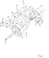
Figur 1- abschnittsweise ein Hubtriebwerk einer nicht gezeigten Hubkolbenmaschine mit einem Wattschen Lenker in einer hypozykloidischen Geradführung,
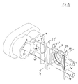
Figur 2- ein weiteres Hubtriebwerk einer nicht gezeigten Hubkolbenmaschine mit einer mittig zwischen Kolbenstangen mit einem einzigen Führungs-Exzenter zusammenwirkender Kulissenstein einer hypozykloidischen Geradführung, und in
Figur 3- die vorgenannten Kulissenführung in Verbindung mit einem von zwei diametral angeordneten Zylindergehäusen der nicht näher gezeigten Hubkolbenmaschine.
- Figure 1
- sections of a lifting engine of a reciprocating piston machine, not shown, with a Watts handlebar in a hypocycloidal straight line,
- Figure 2
- a further lifting engine of a reciprocating piston machine, not shown, with a sliding block of a hypocycloidal straight guide, which cooperates centrally between piston rods with a single guide eccentric, and in
- Figure 3
- the aforementioned link guide in connection with one of two diametrically arranged cylinder housings of the reciprocating piston machine, not shown in detail.
Eine in einer vertikalen Ebene der mit 1 bezeichneten Kurbelwellen-Drehachse
geteiltes Maschinengehäuse einer nicht gezeigten Hubkolbenmaschine umfaßt
gemäß Figur 3 diametral angeordnete Paare von Zylindern 2, 3, deren Zylinderachsen
2' und 3' die Kurbelwellen-Drehachse 1 orthogonal schneiden. In den diametral
angeordneten Paaren von Zylindern 2, 3 einander gegenüberliegende
Hubkolben 4, 4' und 5, 5' gemäß Figur 2 sind über Kolbenstangen 6, 7 miteinander
verbunden. Zur oszillierenden Anordnung der Kolbenpaare 4, 4' und 5, 5' mittels
der Kolbenstangen 6, 7 ist ein Hubtriebwerk 8 mit einer hypozykloidischen Geradführung
9 vorgesehen. Das für beide Ausführungsbeispiele der Figuren 1 und 2 im
Prinzip gleich aufgebaute Hubtriebwerk 8 umfaßt eine durch einen gestuften Linienzug
10 versinnbildlichte Kurbelwelle. Die längs der Zylinderachsen 2' und 3'
gleichgerichtet oszillierenden Kolbenstangen 6 und 7 weisen mittig angeordnete
Ausnehmungen 11, 12 auf zur drehbeweglichen Aufnahme je eines Hub-Exzenters
13, 14 der hypozykloidischen Geradführung 9.A in a vertical plane of the crankshaft axis of rotation designated by 1
divided machine housing of a reciprocating piston machine, not shown
3 diametrically arranged pairs of
Ein zur Kurbelwellen-Drehachse 1 paralleler Linienzug 15 der Kurbelwelle 10 versinnbildlicht
einen Hubzapfen. Auf diesem Hubzapfen 15 sind in dessen äußeren
Endbereichen die in den zueinander parallelen Kolbenstangen 6 und 7 gelagerten
Hub-Exzenter 13, 14 drehbeweglich angeordnet. Aufgrund der gleichgerichtet oszillierenden
Kolbenpaare 4, 4' und 5, 5' sind die Hub-Exzenter13, 14 auf dem gemeinsamen
Hubzapfen 15 gleichgerichtet angeordnet.A line 15 of the
Mittig zwischen diesen Hub-Exzentern 13, 14 umfaßt die hypozykloidische Geradführung
9 weiter einen auf dem Hubzapfen 15 drehbeweglich gelagerten und zu
den Hub-Exzentern 13, 14 diametral angeordneten Führungs-Exzenter 16, der mit
den Hub-Exzentern 13, 14 in einer drehfesten Verbindung steht. Diese Führungs-Exzenter
16 wirkt mit einem zwischen den Kolbenstangen 6, 7 für Hubkolbenpaare
4, 4' und 5, 5' von in Reihe benachbarter Zylinder 2, 3 angeordneten Führungselement
17 der Geradführung 9 zusammen, wobei das quer zu den Bewegungsrichtungen
der Kolbenstangen 6 und 7 im wesentlich gerad geführte Führungselement
17 prinzipiell mit am Maschinengehäuse angeordneten Führungsflächen
zusammenwirkt.In the middle between these
Bei dem ersten Ausführungsbeispiel nach Figur 1 ist die hypozykloidische Geradführung
9 des Hubgetriebes 8 mit einem Wattschen Lenker 18 kombiniert, dessen
Koppel 19 als Führungselement 17 zwischen den Kolbenstangen 6 und 7 auf dem
Führungs-Exzenter 16 gelagert angeordnet ist. Die Koppel 19 ist über schematisch
dargestellte Schwingarme 20 am nicht gezeigten Maschinengehäuse angelenkt.
Vorzugsweise sind die Schwingarme 20 in ihren gehäuseseitigen Anlenkstellen 21
jeweils mit einem relativ zum Maschinengehäuse dreh- und fixierbar angeordneten
Einstell-Exzenter 22 als Mittel zum Ausgleich von Maßtoleranzen ausgerüstet.
Diese Einstell-Exzenter 22 werden nach der Montage des Hubtriebwerkes 8 im
nicht gezeigten Maschinengehäuse nacheinander zunächst in eine Richtung bis
zum Auftreten eines Drehwiderstandes gedreht, anschließend in entgegengesetzter
Richtung bis zum nächsten Widerstand gedreht und abschließend etwa
zwischen beiden Widerstands-Positionen gemittelt fixiert. Während dieser Einstellung
ist die Koppel 19 in ihrer Mittellage angeordnet, wobei die Mitte der den Führungs-Exzenter
16 aufnehmenden Bohrung 23 im wesentlichen mit der Kurbelwellen-Drehachse
1 fluchtet bzw. aufgrund von Maßtoleranzen zu dieser geringfügig
parallel beabstandet ist. Mit den Einstell-Exzentern 22 kann über die im Hubtriebwerk
8 vorhandenen Lagerspiele eine Einstellung der Koppel 19 gefunden werden,
mit der über den gesamten Führungs-Hub der Koppel 19 zwischen ihren Extremlagen
ein Klemmen im Hubtriebwerk sicher vermieden ist.In the first exemplary embodiment according to FIG. 1, the straight line is
Zur Montage der Koppel 19 auf dem Führungs-Exzenter 16 ist dieser aus in axialer
Hubzapfenrichtung verbindbaren Teilen 24, 24' gebildet, wobei zur Erzielung eines
einfacheren Aufbaues an jedem Teil 24, 24' kolbenstangenseitig jeweils einer der
Hub-Exzenter 13 bzw. 14 angeordnet ist sowie ferner eine auf die Achse des Kurbelwellen-Hubzapfens
15 bezogene Ausgleichsmasse 25.To mount the
Bei dem in den Figuren 2 und 3 dargestellten weiteren Ausführungsbeispiel ist der
Führungs-Exzenter 16 der hypozykloidischen Geradführung 9 mit einem zwischen
den Kolbenstangen 6, 7 maschinengehäuseseitige geradlinig gleitbeweglich geführten
Führungselement 17 kombiniert, das, wie aus den Figuren 2 und 3 ersichtlich,
als ein mit parallelen Führungsflächen ausgebildeter Kulissenstein 26 gestaltet
ist. Dieser Kulissenstein 26 wirkt mit gesonderten Führungsleisten 27, 27' zusammen,
die zum Ausgleich von Maßtoleranzen quer zur Führungsrichtung im/am Maschinengehäuse
verlagerbar angeordnet sind. Vorzugsweise sind die Führungsleisten
27, 27' über im Maschinengehäuse angeordnete, hydraulisch beaufschlagte
Kolben 28, 28' verlagerbar angeordnet, wobei die Führungsleisten 27, 27' zusätzlich
relativ zu den Kolben 28, 28' kippbeweglich gelagert sind. Mit dieser erfindungsgemäßen
Anordnung ist eine automatische Einstellung des Kulissensteines
26 mit seiner Bohrungsmitte relativ zur Kurbelwellen-Drehachse 1 erreicht. Bei Anschluß
der Abstütz-Kolben 28, 28' an das Druckschmiersystem der Hubkolbenmaschine
ist eine selbsttätige Spiel- und Ausgleichs-Einstellung erreicht. Der Kulissenstein
26 kann auch unter Zwischenschaltung nicht gezeigter Wälzlagereinrichtungen
bzw. Wälzkörper mit den Führungsleisten 27, 27' zusammenwirken, um
dadurch allein oder in Verbindung mit den verlagerbaren Führungsleisten 27, 27'
ein Klemmen bzw. eine Selbsthemmung der Geradführung 9 in einem OT-Bereich
der Kolben 4, 4', 5, 5' inbesondere bei Kaltstart zu vermeiden.In the further embodiment shown in Figures 2 and 3 is the
Diese erfindungsgemäß hydraulisch unterstützte Geradführung des Kulissensteines
26 entlang der Führungsleisten 27, 27' ermöglicht im Hinblick auf die Montage
des Kulissensteines 26 und die Ausgestaltung des Führungs-Exzenters 16,
den Kulissenstein 26 in Führungsrichtung parallel zu seinen Führungsflächen 29,
29' hälftig geteilt auszubilden. Dadurch kann der Führungs-Exzenter 16 einschließlich
in seinen beiden Stirn bereichen angeordneter Ausgleichsmassen 30 einstückig
ausgebildet sein, womit im Montageverbund mit den Hub-Exzentern 13, 14 eine
steife 3-Scheiben-Exzenter-Kombination erzielt ist.This hydraulically supported straight guidance of the sliding block according to the
Im Rahmen der Erfindung kann anstelle des Kulissensteins 26 als anderes Führungselement
17 ein auf dem Führungs-Exzenter 16 angeordnetes Wälzlager vorgesehen
sein, das über seinen äußeren Lagerring beispielsweise mit den verlagerbar
angeordneten Führungsleisten 27, 27' in gleitbeweglicher Verbindung steht.In the context of the invention, instead of the sliding
Claims (12)
- A reciprocating engine, especially an internal combustion engine, comprising neighbouring cylinders in the direction of the crankshaft in an engine box,characterised in thatcomprising driving gear (8) for reciprocating pistons (4, 4'; 5, 5') which, via piston rods (6, 7) with interposition of a hypocycloidal straight-line guide (9), are in drive connection with reciprocating and guide eccentrics (13, 14, 16) movable in rotation on a crankshaft (10), whereina guide element (17) of the straight-line guide (9) co-operates with guide surfaces disposed on the engine block,a single guide element (17) serves as the straight-line guide of the two neighhouring piston rods (6, 7), and is mounted on a guide eccentric (16) disposed between two adjacent piston rods (6, 7) for pistons (4, 4'; 5, 5') of neighbouring cylinders (2, 3) in line.
- A reciprocating engine according to claim 1, characterised in that each straight-line guide (9) is equipped with means for static and/or dynamic compensation of dimensional tolerances between the engine block and the driving gear.
- A reciprocating engine according to claims 1 and 2, characterised in thatoppositely-disposed reciprocating pistons (4, 4'; 5, 5') in diametrically disposed pairs of cylinders (2, 3) are connected and driven in the same direction via piston rods (6, 7), whereina guide eccentric (16) co-operating with the guide element (17) of the hypocycloidal straight-line guide (9) is disposed so as to be movable in rotation on a crankpin (15) of the crankshaft (10) centrally between two neighbouring piston rods (6, 7), theguide eccentric (16) being non-rotatably cnnnected to eccentric discs (13, 14) of the straight line guide (9) which are disposed so as to be movable in rotation on both sides near the crankpin (15) and engage and are rotatable in the piston rods (6, 7).
- A reciprocating engine according to claims 1 to 3, characterised in thatthe hypocycloidal straight-line guide (9) is combined with a Watt's transversal swinging arm (18), whosecouple (19) is mounted on the guide eccentric (16) between the neighbouring piston rods (6, 7),wherein the swing arms (20) thereof, at at least one of the places (21) where they are pivoted, are equipped with dimensional tolerance-compensating means in the form of an adjusting eccentric (22) disposed so as to be rotatable and fixable relative to the couple (19) and/or to the engine block.
- A reciprocating engine according to claims 1 to 4, characterised in that at each place (21) when the swing arms (20) are pivoted on the side of the engine block, an adjusting eccentric (22) is disposed and designed for automatic adjustment if required.
- A reciprocating engine according to claims 1 to 5, characterised in thatthe guide eccentric (16) is made up of parts (24, 24') connectable in the axial crankpin direction, whereinan eccentric disc (13, 14) and a compensating weight (25) relative to the axis of the crankshaft pin (15) is disposed on each part (24, 24') an the same side as the piston rods.
- A reciprocating engine according to claims 1 to 3, characterised in that the guide eccentric (16) of the hypocycloidal straight-line guide (9) is combined with a guide element (17) guided so as to be slidable in a straight line between the neighbouring piston rods (6, 7) on the same side as the engine block.
- A reciprocating engine according to claims 1 to 3 and 7, characterised in that the guide element (17) is a sliding block (26) formed with parallel guide surfaces (29, 29').
- A reciprocating piston engine according to claims 1 to 3 and 7, characterised in that the slidably guided guide element (17) is a rolling bearing disposed on the guide eccentric (16).
- A reciprocating piston engine according to claims 1 to 3 and 6 to 9, characterised in thateach respective guide element (17) co-operates with separate guide strips (27, 27'), whichin order to compensate dimensional tolerances are mounted so as to be movable transversely to the guide direction in/on the engine block and if requiredco-operate with the sliding block (26) via rolling members.
- A reciprocating piston engine according to claims 1 to 3 and 6 to 10, characterised in thatthe guide strips (27, 27') are disposed so as to be movable via hydraulically actuated pistons (28, 28') disposed in the engine block, whereinthe guide strips (27, 27') are tiltable relative to the pistons (28, 28').
- A reciprocating engine according to claims 1 to 3 and 6 to 11, characterised in thatthe guide eccentric (16) is in one piece including compensating weights (30) disposed in its two end regions andthe sliding block (26) is divided in half in the guide direction parallel to its guide surfaces (29, 29').
Applications Claiming Priority (3)
| Application Number | Priority Date | Filing Date | Title |
|---|---|---|---|
| DE19504890A DE19504890A1 (en) | 1995-02-14 | 1995-02-14 | Reciprocating machine with cylinders adjacent in the direction of the crankshaft in a machine housing |
| DE19504890 | 1995-02-14 | ||
| PCT/EP1996/000631 WO1996025587A1 (en) | 1995-02-14 | 1996-02-14 | Reciprocating piston engine with adjacent cylinders in the crankshaft direction in an engine case |
Publications (2)
| Publication Number | Publication Date |
|---|---|
| EP0809749A1 EP0809749A1 (en) | 1997-12-03 |
| EP0809749B1 true EP0809749B1 (en) | 1999-04-07 |
Family
ID=7753920
Family Applications (1)
| Application Number | Title | Priority Date | Filing Date |
|---|---|---|---|
| EP96904775A Expired - Lifetime EP0809749B1 (en) | 1995-02-14 | 1996-02-14 | Reciprocating piston engine with adjacent cylinders in the crankshaft direction in an engine case |
Country Status (8)
| Country | Link |
|---|---|
| US (1) | US5943987A (en) |
| EP (1) | EP0809749B1 (en) |
| JP (1) | JP3676812B2 (en) |
| KR (1) | KR100380643B1 (en) |
| CN (1) | CN1076073C (en) |
| DE (2) | DE19504890A1 (en) |
| ES (1) | ES2130801T3 (en) |
| WO (1) | WO1996025587A1 (en) |
Cited By (2)
| Publication number | Priority date | Publication date | Assignee | Title |
|---|---|---|---|---|
| DE102005024361A1 (en) * | 2005-05-27 | 2006-12-07 | Bayerische Motoren Werke Ag | Drive unit for motor vehicle e.g. passenger motor vehicle has first and second internal combustion engine connected by clutch mechanism depending upon power required whereby internal combustion engine has hypocycloidic crank drive |
| DE102014018561B3 (en) * | 2014-12-15 | 2016-01-28 | Gert Fischer | Combustion engine with in-line cylinders |
Families Citing this family (21)
| Publication number | Priority date | Publication date | Assignee | Title |
|---|---|---|---|---|
| DE19607920A1 (en) | 1996-03-01 | 1997-09-04 | Bayerische Motoren Werke Ag | Hypocycloidal crank mechanism for reciprocating piston machines, in particular internal combustion engines |
| DE19623552A1 (en) * | 1996-06-13 | 1997-12-18 | Bayerische Motoren Werke Ag | Reciprocating piston machine with a hypocycloid piston lifting gear with Watt's guidance, in particular with pistons in opposing cylinders |
| ITTO980080A1 (en) * | 1998-02-02 | 1999-08-02 | Fiat Auto Spa | CRANKCASE FOR AN ALTERNATIVE MACHINE, PARTICULARLY FOR AN INTERNAL COMBUSTION ENGINE |
| UA50790C2 (en) * | 1999-03-09 | 2002-11-15 | Олексій Феліксович Вуль | Piston machine with rod-less mechanism |
| CN100436779C (en) * | 2004-08-18 | 2008-11-26 | 何观龙 | Piston zero side pressure technology and apparatus of high efficient internal-combustion engine |
| US7878081B2 (en) * | 2004-12-13 | 2011-02-01 | Gregory S Sundheim | Portable, refrigerant recovery unit |
| US7328682B2 (en) * | 2005-09-14 | 2008-02-12 | Fisher Patrick T | Efficiencies for piston engines or machines |
| US7654802B2 (en) * | 2005-12-22 | 2010-02-02 | Newport Medical Instruments, Inc. | Reciprocating drive apparatus and method |
| WO2008010490A1 (en) * | 2006-07-18 | 2008-01-24 | Univ Shizuoka Nat Univ Corp | Cycloid reciprocating engine and pump employing this crank mechanism |
| EP2076693A1 (en) * | 2006-10-16 | 2009-07-08 | Wintech International PTY LTD | Hypocycloidal transmission |
| WO2008085920A2 (en) * | 2007-01-05 | 2008-07-17 | Efficient-V, Inc. | Motion translation mechanism |
| GB0907496D0 (en) * | 2009-05-01 | 2009-06-10 | Hall Keith G | Engines and drives |
| CN101672264B (en) * | 2009-09-30 | 2011-10-19 | 浙江鸿友压缩机制造有限公司 | Linearly-reciprocating piston compressor |
| CN101886693B (en) * | 2010-07-02 | 2014-02-12 | 北京中清能发动机技术有限公司 | Crank-slider mechanism, parts and equipment |
| JP6084163B2 (en) * | 2010-12-06 | 2017-02-22 | 北京中清能発動機技術有限公司 | Crank circular slider mechanism, reciprocating part, engine block, internal combustion engine, and compressor |
| US9708976B1 (en) * | 2011-09-30 | 2017-07-18 | Warren Engine Company, Inc. | Opposed piston engine and elements thereof |
| US9119382B2 (en) | 2013-02-26 | 2015-09-01 | Tyson Foods Inc. | Portable basket colony for growing and transport and method of use |
| CN104154195A (en) * | 2014-07-21 | 2014-11-19 | 苏州市华宁机械制造有限公司 | Double-eccentric driving guide-bar mechanism |
| CN104747674A (en) * | 2015-01-23 | 2015-07-01 | 陈桢皓 | Power output device, air cylinder and diesel engine |
| AT518769B1 (en) * | 2016-08-18 | 2018-01-15 | Ecool Advanced Urban Eng Gmbh | Internal combustion engine |
| JP6734464B1 (en) * | 2019-12-26 | 2020-08-05 | 竹本 護 | Vibration-free reciprocating engine |
Family Cites Families (33)
| Publication number | Priority date | Publication date | Assignee | Title |
|---|---|---|---|---|
| DE271755C (en) * | ||||
| US848635A (en) * | 1906-04-13 | 1907-04-02 | George S Comstock | Transmission mechanism. |
| US908605A (en) * | 1907-07-05 | 1909-01-05 | Fred C Olin | Crank and yoke connection. |
| US1233621A (en) * | 1914-08-12 | 1917-07-17 | Henry W Jessup | Valve mechanism for internal-combustion engines. |
| US1866702A (en) * | 1930-04-15 | 1932-07-12 | Cooper Bessemer Corp | Driving connection |
| DE725239C (en) * | 1941-03-11 | 1942-09-17 | Ferdinand Meyer | Eccentric gear |
| US2302851A (en) * | 1941-11-28 | 1942-11-24 | Joseph F Gelser | Internal combustion engine |
| US2367963A (en) * | 1942-07-22 | 1945-01-23 | Ricardo Harry Ralph | Two-cycle sleeve-valve engine |
| US2513514A (en) * | 1945-10-08 | 1950-07-04 | Robert A Poage | Piston and crankshaft connecting means for internal-combustion engines |
| DE898372C (en) * | 1951-11-30 | 1953-11-30 | Max Ruediger | Fast-running two-stroke engine with charge pump with compression ignition, slot-controlled and with exhaust valve in the cylinder cover |
| US3195420A (en) * | 1963-10-17 | 1965-07-20 | Donald J Johannsen | Dual piston unit for internal combustion engine |
| GB1060372A (en) * | 1963-11-13 | 1967-03-01 | Bancroft Charles | Improvements in or relating to reciprocating compressors, pumps, engines and the like |
| DE1301323B (en) * | 1965-06-04 | 1969-08-21 | Elsbett L | Connecting rod for high-performance reciprocating internal combustion engines |
| US3386429A (en) * | 1966-07-11 | 1968-06-04 | Earl M. Trammell Jr. | Internal combustion engine |
| FR2260199B1 (en) * | 1974-02-05 | 1977-03-04 | Elhyco Ag | |
| DE2519908A1 (en) * | 1975-05-03 | 1976-11-11 | Juergen Dipl Ing Lambrecht | Eccentric rotating shaft in reciprocating piston engine - carries auxiliary eccentric discs, converting linear movement to rotary |
| GB2038937A (en) * | 1979-01-04 | 1980-07-30 | Suzuku K | Reciprocating Piston Engine |
| FR2482190A1 (en) * | 1980-05-08 | 1981-11-13 | Abeillon Jackie | POWER AMPLIFIER FOR HEAT ENGINES OR OTHER |
| US4559686A (en) * | 1980-06-11 | 1985-12-24 | Tecumseh Products Company | Method of assembling a hermetic compressor |
| US4450754A (en) * | 1980-08-18 | 1984-05-29 | Liljequist Jon L | Mechanical arrangements for piston-crankshaft devices |
| GB8608237D0 (en) * | 1986-04-04 | 1986-05-08 | Collins Motor Corp Ltd | Reciprocatory positive displacement machines |
| DE3636873A1 (en) * | 1986-10-30 | 1988-05-11 | Forsch Kraftfahrwesen Und Fahr | Synchromesh transmission on a hypocycloidal transmission for a reciprocating piston engine |
| GB8712645D0 (en) * | 1987-05-29 | 1987-07-01 | Collins Motor Corp Ltd | Interconnecting rotary & reciprocatory motion |
| DE3824521A1 (en) * | 1988-07-20 | 1990-01-25 | Heinrich Rode | Hypocycloidal gear motor (internal combustion engine) |
| GB2229248A (en) * | 1989-03-15 | 1990-09-19 | Ford Motor Co | Phase change mechanism |
| DE3927593A1 (en) * | 1989-08-22 | 1991-02-28 | Bayerische Motoren Werke Ag | LIFTING GEAR, ESPECIALLY FOR LIFTING PISTON MACHINES |
| DK0516727T3 (en) * | 1990-02-21 | 1994-09-26 | Collins Motor Corp Ltd | Coupled rotating and reciprocating movements |
| DE4108311C2 (en) * | 1991-03-14 | 2000-09-21 | Bayerische Motoren Werke Ag | Hypocycloid jacks for boxer type reciprocating machines |
| DE4142385A1 (en) * | 1991-12-20 | 1993-06-24 | Bayerische Motoren Werke Ag | Hypocycloid drive for IC engine - has bearing journals for pairs of cylinders formed as part of crank cheeks |
| DE4204319A1 (en) * | 1992-02-13 | 1993-08-19 | Norbert Kraemer | IC engine with external ignition - has two-part central shaft with end discs and central cage, which guides shaft, held eccentrically in discs |
| US5331926A (en) * | 1993-07-23 | 1994-07-26 | Denner, Inc. | Dwelling scotch yoke engine |
| DE4412165A1 (en) * | 1994-04-08 | 1994-09-01 | Viktor Hammermeister | Crank mechanism for converting rectilinear reciprocating movements into rotary movements and vice versa |
| DE19607920A1 (en) * | 1996-03-01 | 1997-09-04 | Bayerische Motoren Werke Ag | Hypocycloidal crank mechanism for reciprocating piston machines, in particular internal combustion engines |
-
1995
- 1995-02-14 DE DE19504890A patent/DE19504890A1/en not_active Withdrawn
-
1996
- 1996-02-14 CN CN96191881A patent/CN1076073C/en not_active Expired - Fee Related
- 1996-02-14 KR KR1019970704503A patent/KR100380643B1/en not_active Expired - Fee Related
- 1996-02-14 JP JP52466296A patent/JP3676812B2/en not_active Expired - Fee Related
- 1996-02-14 ES ES96904775T patent/ES2130801T3/en not_active Expired - Lifetime
- 1996-02-14 DE DE59601612T patent/DE59601612D1/en not_active Expired - Lifetime
- 1996-02-14 US US08/894,178 patent/US5943987A/en not_active Expired - Lifetime
- 1996-02-14 WO PCT/EP1996/000631 patent/WO1996025587A1/en not_active Ceased
- 1996-02-14 EP EP96904775A patent/EP0809749B1/en not_active Expired - Lifetime
Cited By (2)
| Publication number | Priority date | Publication date | Assignee | Title |
|---|---|---|---|---|
| DE102005024361A1 (en) * | 2005-05-27 | 2006-12-07 | Bayerische Motoren Werke Ag | Drive unit for motor vehicle e.g. passenger motor vehicle has first and second internal combustion engine connected by clutch mechanism depending upon power required whereby internal combustion engine has hypocycloidic crank drive |
| DE102014018561B3 (en) * | 2014-12-15 | 2016-01-28 | Gert Fischer | Combustion engine with in-line cylinders |
Also Published As
| Publication number | Publication date |
|---|---|
| KR100380643B1 (en) | 2003-07-18 |
| US5943987A (en) | 1999-08-31 |
| EP0809749A1 (en) | 1997-12-03 |
| JPH11500200A (en) | 1999-01-06 |
| DE19504890A1 (en) | 1996-08-22 |
| DE59601612D1 (en) | 1999-05-12 |
| ES2130801T3 (en) | 1999-07-01 |
| CN1076073C (en) | 2001-12-12 |
| CN1173907A (en) | 1998-02-18 |
| JP3676812B2 (en) | 2005-07-27 |
| WO1996025587A1 (en) | 1996-08-22 |
Similar Documents
| Publication | Publication Date | Title |
|---|---|---|
| EP0809749A1 (en) | Reciprocating piston engine with adjacent cylinders in the crankshaft direction in an engine case | |
| EP2524127B1 (en) | Inline internal combustion engine with multiple link crank drive having a single balancer shaft to comprensate second order momentum forces | |
| DD256894A5 (en) | PISTON COMBUSTION ENGINES | |
| DE2639260C3 (en) | Multi-cylinder reciprocating internal combustion engine | |
| DE19607920A1 (en) | Hypocycloidal crank mechanism for reciprocating piston machines, in particular internal combustion engines | |
| EP0815370B1 (en) | Hypocycloidal crank mechanism for piston engines, engines especially for opposed-cylinder internal combustion engines | |
| DE102010004588B4 (en) | Internal combustion engine with extended expansion stroke and balance weights on the eccentric shaft | |
| DE10348345B4 (en) | Reciprocating internal combustion engine | |
| DE102012008244B4 (en) | Multi-joint crank drive of an internal combustion engine | |
| DE2816429C2 (en) | Mechanical press drive | |
| DE69936522T3 (en) | RIGID CRANKSHAFT SUPPORT AND ACTUATOR | |
| WO2013110470A1 (en) | Multi-joint crank drive of an internal combustion engine, and method for assembling a multi-joint crank drive | |
| DE3927593A1 (en) | LIFTING GEAR, ESPECIALLY FOR LIFTING PISTON MACHINES | |
| DE3642681A1 (en) | Crankshaft, particularly for reciprocating-piston combustion engines | |
| DE102013019214B3 (en) | Multi-joint crank drive of an internal combustion engine and method for operating a multi-joint crank drive | |
| DE3420956A1 (en) | Synchromesh transmission for a central, equal-armed straight-sliding crank mechanism of a reciprocating piston engine | |
| DE19500854C2 (en) | Reciprocating machine | |
| WO1988004356A1 (en) | Crank mechanism, in particular for alternating piston engines | |
| WO2015090605A1 (en) | Coupling element for a multi-joint crank drive and multi-joint crank drive | |
| DE866115C (en) | Piston machine with a swash plate, in particular an internal combustion piston machine | |
| DE4237463C2 (en) | Differential gear | |
| DE2723269C2 (en) | Multi-cylinder reciprocating engine | |
| DE102009038850B4 (en) | Boxer engine with backdrop connecting rod | |
| DE2602436A1 (en) | Piston engine with sliding and rotating pistons - has off centre piston rod with plain bearing mounted on crankpin | |
| DE514780C (en) | Axial piston machine, in particular internal combustion engine, in which the pistons are connected to a swash plate |
Legal Events
| Date | Code | Title | Description |
|---|---|---|---|
| PUAI | Public reference made under article 153(3) epc to a published international application that has entered the european phase |
Free format text: ORIGINAL CODE: 0009012 |
|
| 17P | Request for examination filed |
Effective date: 19970528 |
|
| AK | Designated contracting states |
Kind code of ref document: A1 Designated state(s): DE ES FR GB IT |
|
| GRAG | Despatch of communication of intention to grant |
Free format text: ORIGINAL CODE: EPIDOS AGRA |
|
| 17Q | First examination report despatched |
Effective date: 19980623 |
|
| GRAG | Despatch of communication of intention to grant |
Free format text: ORIGINAL CODE: EPIDOS AGRA |
|
| GRAH | Despatch of communication of intention to grant a patent |
Free format text: ORIGINAL CODE: EPIDOS IGRA |
|
| GRAH | Despatch of communication of intention to grant a patent |
Free format text: ORIGINAL CODE: EPIDOS IGRA |
|
| GRAA | (expected) grant |
Free format text: ORIGINAL CODE: 0009210 |
|
| AK | Designated contracting states |
Kind code of ref document: B1 Designated state(s): DE ES FR GB IT |
|
| GBT | Gb: translation of ep patent filed (gb section 77(6)(a)/1977) |
Effective date: 19990408 |
|
| REF | Corresponds to: |
Ref document number: 59601612 Country of ref document: DE Date of ref document: 19990512 |
|
| ET | Fr: translation filed | ||
| REG | Reference to a national code |
Ref country code: ES Ref legal event code: FG2A Ref document number: 2130801 Country of ref document: ES Kind code of ref document: T3 |
|
| PLBE | No opposition filed within time limit |
Free format text: ORIGINAL CODE: 0009261 |
|
| STAA | Information on the status of an ep patent application or granted ep patent |
Free format text: STATUS: NO OPPOSITION FILED WITHIN TIME LIMIT |
|
| 26N | No opposition filed | ||
| REG | Reference to a national code |
Ref country code: GB Ref legal event code: IF02 |
|
| PGFP | Annual fee paid to national office [announced via postgrant information from national office to epo] |
Ref country code: IT Payment date: 20110224 Year of fee payment: 16 Ref country code: FR Payment date: 20110315 Year of fee payment: 16 |
|
| PGFP | Annual fee paid to national office [announced via postgrant information from national office to epo] |
Ref country code: ES Payment date: 20110131 Year of fee payment: 16 Ref country code: DE Payment date: 20110402 Year of fee payment: 16 |
|
| PGFP | Annual fee paid to national office [announced via postgrant information from national office to epo] |
Ref country code: GB Payment date: 20120223 Year of fee payment: 17 |
|
| REG | Reference to a national code |
Ref country code: FR Ref legal event code: ST Effective date: 20121031 |
|
| PG25 | Lapsed in a contracting state [announced via postgrant information from national office to epo] |
Ref country code: IT Free format text: LAPSE BECAUSE OF NON-PAYMENT OF DUE FEES Effective date: 20120214 |
|
| REG | Reference to a national code |
Ref country code: DE Ref legal event code: R119 Ref document number: 59601612 Country of ref document: DE Effective date: 20120901 |
|
| PG25 | Lapsed in a contracting state [announced via postgrant information from national office to epo] |
Ref country code: FR Free format text: LAPSE BECAUSE OF NON-PAYMENT OF DUE FEES Effective date: 20120229 |
|
| PG25 | Lapsed in a contracting state [announced via postgrant information from national office to epo] |
Ref country code: DE Free format text: LAPSE BECAUSE OF NON-PAYMENT OF DUE FEES Effective date: 20120901 |
|
| REG | Reference to a national code |
Ref country code: ES Ref legal event code: FD2A Effective date: 20130708 |
|
| PG25 | Lapsed in a contracting state [announced via postgrant information from national office to epo] |
Ref country code: ES Free format text: LAPSE BECAUSE OF NON-PAYMENT OF DUE FEES Effective date: 20120215 |
|
| GBPC | Gb: european patent ceased through non-payment of renewal fee |
Effective date: 20130214 |
|
| PG25 | Lapsed in a contracting state [announced via postgrant information from national office to epo] |
Ref country code: GB Free format text: LAPSE BECAUSE OF NON-PAYMENT OF DUE FEES Effective date: 20130214 |