EP3084151B1 - Regelungsverfahren für einen organischen rankine kreislauf - Google Patents
Regelungsverfahren für einen organischen rankine kreislauf Download PDFInfo
- Publication number
- EP3084151B1 EP3084151B1 EP14833208.3A EP14833208A EP3084151B1 EP 3084151 B1 EP3084151 B1 EP 3084151B1 EP 14833208 A EP14833208 A EP 14833208A EP 3084151 B1 EP3084151 B1 EP 3084151B1
- Authority
- EP
- European Patent Office
- Prior art keywords
- organic
- fluid
- organic fluid
- turbine
- phase
- Prior art date
- Legal status (The legal status is an assumption and is not a legal conclusion. Google has not performed a legal analysis and makes no representation as to the accuracy of the status listed.)
- Active
Links
Images


Classifications
-
- F—MECHANICAL ENGINEERING; LIGHTING; HEATING; WEAPONS; BLASTING
- F01—MACHINES OR ENGINES IN GENERAL; ENGINE PLANTS IN GENERAL; STEAM ENGINES
- F01K—STEAM ENGINE PLANTS; STEAM ACCUMULATORS; ENGINE PLANTS NOT OTHERWISE PROVIDED FOR; ENGINES USING SPECIAL WORKING FLUIDS OR CYCLES
- F01K13/00—General layout or general methods of operation of complete plants
- F01K13/02—Controlling, e.g. stopping or starting
-
- F—MECHANICAL ENGINEERING; LIGHTING; HEATING; WEAPONS; BLASTING
- F01—MACHINES OR ENGINES IN GENERAL; ENGINE PLANTS IN GENERAL; STEAM ENGINES
- F01K—STEAM ENGINE PLANTS; STEAM ACCUMULATORS; ENGINE PLANTS NOT OTHERWISE PROVIDED FOR; ENGINES USING SPECIAL WORKING FLUIDS OR CYCLES
- F01K11/00—Plants characterised by the engines being structurally combined with boilers or condensers
- F01K11/02—Plants characterised by the engines being structurally combined with boilers or condensers the engines being turbines
-
- F—MECHANICAL ENGINEERING; LIGHTING; HEATING; WEAPONS; BLASTING
- F01—MACHINES OR ENGINES IN GENERAL; ENGINE PLANTS IN GENERAL; STEAM ENGINES
- F01K—STEAM ENGINE PLANTS; STEAM ACCUMULATORS; ENGINE PLANTS NOT OTHERWISE PROVIDED FOR; ENGINES USING SPECIAL WORKING FLUIDS OR CYCLES
- F01K25/00—Plants or engines characterised by use of special working fluids, not otherwise provided for; Plants operating in closed cycles and not otherwise provided for
- F01K25/08—Plants or engines characterised by use of special working fluids, not otherwise provided for; Plants operating in closed cycles and not otherwise provided for using special vapours
Definitions
- the present invention is related to a control method for vapor thermodynamic cycles and is particularly suitable for an organic Rankine cycle (hereafter also ORC).
- thermodynamic cycle is a cyclical finite sequence of thermodynamic transformations (for example, isotherm, isochoric, isobar or adiabatic). At the end of each cycle the system comes back to its initial state.
- a Rankine cycle is a thermodynamic cycle composed of two adiabatic transformations and two isobar transformations. Aim of the Rankine cycle is to transform heat in mechanical work and all kind of vapor machines are based on such a cycle.
- This cycle is mainly used in thermo-electrical plants for electrical energy production and uses water as working fluid, both in liquid and in vapor state, in the so called vapor turbine.
- an ORC apparatus comprises one or more pumps for the organic fluid feeding, one or more heat exchangers for performing pre-heating, vaporization and eventually overheating, a vapor turbine for expanding the fluid, a condenser for transforming the vapor into liquid and in some cases a regenerator for heat recovering, downstream of the turbine, i.e. upstream of the condenser.
- Patent Publication US-2011/308252 discloses an organic Rankine cycle wherein the turbine inlet condition is controlled in order to avoid formation of a liquid phase of the organic fluid at the turbine inlet.
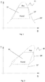
- ORC cycles one of the advantages of ORC cycles is that organic fluids, having a high molecular mass, show a saturation curve (in the graph temperature-entropy, T-S) with a right branch 12' having a positive slope ( Fig.2 ). Instead, the steam saturation curve shows a right branch 11' having a negative slope ( Fig.1 ).
- intersection can arise in the upper portion of the right branch of the saturation curve - quasi-critical or hypercritical cycles ( Fig. 3 ) - or in the lower portion of the right branch, in case of organic fluids having a lower molecular mass, which can have the right branch of the saturation curve either with a small positive slope or even with a small negative slope.
- An aspect of the present invention is a control method for ORC cycles, said method controlling the liquid supply to the heat exchangers of the high pressure portion of the ORC cycle, in order to avoid the mentioned inconvenience.
- Another aspect of the invention is an apparatus configured to execute the above method.
- a first aspect of the invention is a method of controlling an Organic Rankine Cycle system, the system comprising at least one feed pump, at least one heat exchanger, an expansion turbine and a condenser, the organic Rankine cycle comprising a feeding phase of an organic working fluid, a heating and vaporization phase of the same working fluid, an expansion and condensation phase of the same working fluid, eventually a regeneration phase, wherein said method controls an adjusted variable, hereafter defined as "similar to an overheating" of the organic fluid by means of a controller that acts by varying a control variable, which is a parameter of the organic fluid in its liquid phase.
- said adjusted variable is a temperature difference between a current temperature of the organic fluid in vapor phase at the turbine inlet and a temperature threshold under which the expansion phase involves the formation of a liquid phase of the organic fluid.
- an apparatus configured to realize the above method and comprising means for controlling said adjusted variable, "similar to a overheating" of the organic fluid, said means acting by varying a control variable, which is a parameter of the organic fluid in its liquid phase, wherein said adjusted variable is a temperature difference between a current temperature of the organic fluid in vapor phase at the turbine inlet and a temperature threshold under which the expansion phase involves the formation of a liquid phase of the organic fluid.
- An advantage of this aspect is that the difference between a current temperature of the organic fluid in vapor phase at the turbine inlet and a temperature threshold under which the expansion phase involves the formation of a liquid phase of the organic fluid can be easily determined, when the thermodynamic characteristics of the organic fluid are known as a function of the supply pressure of said fluid and, for certain organic fluids, also as a function of the condensation pressure. In this way, during the expansion in the turbine, the liquid formation is avoided, and consequently the risk to worsen the turbine efficiency.
- said control variable is the flow rate of the organic fluid at the inlet of said at least one heat exchanger.
- control means are configured for acting on the flow rate of the organic fluid at the inlet of said at least one heat exchanger.
- An advantage of this embodiment is to keep the adjusted variable equal to the predetermined set-point, by means of the adjustment of the flow rate of the organic fluid .
- the adjustment of the flow rate of the organic fluid at the inlet of the heat exchanger is realized by varying the rotational speed of the feed pump of the organic fluid.
- control means are configured for varying the rotational speed of the feed pump of the organic fluid.
- An advantage of this embodiment is that the rotational speed of the feed pump can be easily controlled.
- the adjustment of the flow rate of the organic fluid at the inlet of the heat exchanger is realized by varying the opening degree of a valve, located downstream of the feed pump of the organic fluid.
- control means are configured for varying the opening degree of a valve, located downstream of the feed pump of the organic fluid.
- An advantage of this embodiment is to execute an alternative flow rate adjustment, if the feed pump of the organic fluid operates at fixed revolution number.
- an organic Rankine cycle system comprising at least one feed pump, at least one heat exchanger, an expansion turbine, a condenser and a controller configured to operate a method according to one of the above embodiments.
- the method according to one of its embodiments can be carried out with the help of a computer program comprising a program-code for carrying out all the steps of the method described above, and in the form of computer program product comprising the computer program.
- the computer program product can be configured as a control apparatus for an organic Rankine cycle, comprising an Electronic Control Unit (ECU), a data carrier, associated to the ECU, and a computer program stored in the data carrier, so that the control apparatus defines the embodiments described in the same way as the method. In this case, when the control apparatus executes the computer program all the steps of the method described above are carried out.
- ECU Electronic Control Unit
- data carrier associated to the ECU
- an ORC system typically comprises at least a feed pump 2 for supplying an organic fluid in liquid phase to at least a heat exchanger 3.
- the heat exchanger which on its turn can comprise a pre-heater, an evaporator and an over-heater, the organic fluid is heated until the transformation in saturated vapor or even in overheated vapor happens.
- the vapor crosses an expansion turbine (where the mechanical work of the ORC cycle is obtained) and finally crosses a condenser 6, which transforms the vapor into liquid, and can come back to the feed pump for the subsequent cycle.
- a regenerator can be provided between the turbine 5 and the condenser 6, a regenerator can be provided. The regenerator exchanges heat between the organic fluid in liquid phase, flowing from the feed pump to the heat exchanger, and the organic fluid in vapor phase, flowing towards the condenser.
- a saturation curve 12 of an organic fluid having a middle or high molecular mass, with respect to the water molecular mass
- a saturation curve 11 of the water is that for the organic fluid the right branch 12' of the curve shows a positive slope, while for the water-steam system the right branch 11' of the curve shows a negative slope.
- a typical cycle, without overheating, i.e. with a saturated vapor expansion, is respectively referenced with 13 (steam cycle, Fig. 1 ) and with 14 (ORC cycle, Fig. 2 ).
- the two cycles differ because the steam expansion 13' in the turbine fall inside its own saturation curve, with liquid formation, while the organic fluid expansion 14' in the turbine arises outside the saturation curve, that is to say in the overheated vapor area. Therefore, during the turbine expansion, there is no liquid formation and, consequently, no turbine damage.
- Fig. 3 shows a hypercritical thermodynamic cycle 15 of an organic fluid (it can be the same as in Fig. 2 ).
- the cycle is called hypercritical, since the evaporation pressure at the expansion start 16 is higher than the pressure of the critical point 16'.
- the expansion curve 15' of the vapor in the turbine can intersect the saturation curve of the T-S diagram and therefore, also for ORC cycles there is liquid formation in the turbine.
- the present invention start considering that for each feeding pressure value of the vapor in the turbine, there is a temperature threshold T lim , under which the expansion would intersect the saturation curve. On the contrary, if a higher temperature than this temperature threshold is kept, the expansion in the turbine takes place in a safety area, in other words in the overheated vapor area, without intersecting the saturation curve.
- the temperature difference ⁇ T between the vapor temperature at the turbine inlet and this temperature threshold T lim is called "similar to an overheating".
- such parameter "similar to an overheating” represents a safety margin with respect to the critical condition, which would cause liquid formation during the expansion in the turbine.
- This condition is expressed by the temperature threshold T lim , to whom an expansion phase E lim tangent to the saturation curve corresponds.
- a map or a theoretical-experimental curve can be defined, associating for each pressure value in the turbine a corresponding temperature threshold. For each point, such temperature threshold can be calculated, simulating the vapor expansion in the turbine. It can be observed that, in case of subcritical cycles, for a certain portion of the expansion curve, such couples of points are the couples saturation pressure - saturation temperature of the fluid, since that, in this expansion curve portion the saturation temperature ensures not to have expansion inside the saturation curve.
- the control apparatus performs a cycle adjustment to keep the parameter "similar to an overheating" equal to the predetermined set point.
- the adjustment is typically performed by acting on the flow rate of the organic fluid entering the heat exchangers, which heats and vaporizes said fluid.
- the predetermined set point value ⁇ Tsp is compared with the current "similar to an overheating" parameter ⁇ Tact (the adjusted variable) and the control action is carried out by a controller 20, for example a PID controller (proportional, integral and derivative), whose output is the adjustment 21 of the control variable, that is to say the flow rate of the fluid entering the heat exchangers.
- this set point ranges between a few degrees and a few decades of degrees and consequently a high accuracy in calculating the above mentioned points of the curve and/or interpolating said curve is not required.
- the map associating a temperature threshold to each pressure value of the vapor in the turbine is predetermined and is an input parameter of the control method.
- control action can be related to the rotational speed V of the feed pump 2 or to the opening degree ⁇ of a valve, located downstream of said feed pump (working the pump at a fixed revolution number) or to another control parameter, influencing the parameter to be adjusted (for example, the hot source temperature).
- the intersection of the saturation curve can arise in the lower portion of the right branch of the T-S diagram, corresponding to lower condensation pressures.
- the threshold temperature values can be more conveniently corrected as a function of the condensation pressure.
- the present method can also be suitable for a slow ramp up of the system.
- beginning the starting phase with substantially high values of the temperature difference ⁇ T would lead to a quite low pressure values in the turbine: the temperature difference value is limited on the upper part by the maximum temperature of the hot thermal source and therefore, increasing the variable ⁇ T, the maximum pressure value reachable in the ORC cycle decreases. Later, it would be possible to gradually decrease the value of the temperature difference ⁇ T, until the ORC cycle will reach the target conditions (either subcritical or hypercritical). In this way, for example, the transient phase from a subcritical cycle to a hypercritical cycle can be gradually performed.
Landscapes
- Engineering & Computer Science (AREA)
- Chemical & Material Sciences (AREA)
- Combustion & Propulsion (AREA)
- Mechanical Engineering (AREA)
- General Engineering & Computer Science (AREA)
- Engine Equipment That Uses Special Cycles (AREA)
- Control Of Turbines (AREA)
Claims (9)
- Verfahren der Kontrolle eines Systems eines organischen Rankine-Zyklus,
wobei das System mindestens eine Förderpumpe (2), mindestens einen Wärmetauscher (3), eine Expansionsturbine (5) und einen Kondensator (6), umfasst
wobei der organische Rankine-Zyklus eine Zufuhrphase eines organischen Arbeitsfluides, eine Erwärmungs- und Verdampfungsphase desselben Arbeitsfluides, eine Expansionsphase und eine Kondensationsphase desselben Arbeitsfluides umfasst,
wobei die genannte Methode eine geregelte Variable (X) steuert, die eine Funktion einer Überhitzung des organischen Fluides mittels eines Reglers (20) ist, der durch Modifizieren einer Steuervariablen (Y) wirkt, die ein Parameter des organischen Fluides in seiner flüssigen Phase ist,
wobei das Verfahren dadurch gekennzeichnet ist, dass die genannte geregelte Variable (X) eine Temperaturdifferenz (ΔT) zwischen einer aktuellen Temperatur des organischen Fluides in der Dampfphase am Turbineneinlass und einer Temperaturschwelle (Tlim) ist, unter derer die Expansionsphase die Bildung einer flüssigen Phase des organischen Fluides umfasst. - Verfahren nach Anspruch 1, wobei die genannte Temperaturschwelle (Tlim) eine Funktion des Dampfdrucks in der Turbine ist.
- Verfahren nach Anspruch 1 oder 2, wobei die Steuervariable (Y) die Flussrate (Q) des organischen Fluides am Einlass des mindestens einen Wärmetauschers ist.
- Verfahren nach Anspruch 3, wobei die Regulierung der Flussrate (Q) des organischen Fluides am Einlass des Wärmetauschers durch Modifizieren der Drehgeschwindigkeit (V) der Zufuhrpumpe (2) des organischen Fluides durchgeführt wird.
- Verfahren nach Anspruch 3 oder 4, wobei die Regulierung der Flussrate (Q) des organischen Fluides am Einlass des Wärmetauschers durch Modifizieren des Öffnungsgrads (x) eines Ventils ausgeführt wird, das stromabwärts der Pumpe angeordnet ist.
- System eines organischen Rankine-Zyklus mit mindestens einer Förderpumpe (2), mindestens einem Wärmetauscher (3), einer Entspannungsturbine (5), einem Kondensator (6) und einem Regler (20) der derart ausgebildet ist, dass er ein Verfahren nach einem der vorhergehenden Ansprüche ausführt.
- Computerprogramm mit einer Software, die zur Durchführung des Verfahrens nach einem der Ansprüche 1 bis 5 geeignet ist.
- Computerprogrammprodukt, bei dem das Computerprogramm nach Anspruch 7 gespeichert ist.
- Steuergerät für ein System eines organischen Rankine-Zyklus, mit einem Regler, einem dem Regler zugeordneten Datenträger und einem im Datenträger gespeicherten Produkt eines Computerprogramms nach Anspruch 8.
Applications Claiming Priority (2)
| Application Number | Priority Date | Filing Date | Title |
|---|---|---|---|
| IT000184A ITBS20130184A1 (it) | 2013-12-19 | 2013-12-19 | Metodo di controllo di un ciclo rankine organico |
| PCT/IB2014/066910 WO2015092649A1 (en) | 2013-12-19 | 2014-12-15 | Control method for an organic rankine cycle |
Publications (2)
| Publication Number | Publication Date |
|---|---|
| EP3084151A1 EP3084151A1 (de) | 2016-10-26 |
| EP3084151B1 true EP3084151B1 (de) | 2018-01-10 |
Family
ID=50001101
Family Applications (1)
| Application Number | Title | Priority Date | Filing Date |
|---|---|---|---|
| EP14833208.3A Active EP3084151B1 (de) | 2013-12-19 | 2014-12-15 | Regelungsverfahren für einen organischen rankine kreislauf |
Country Status (7)
| Country | Link |
|---|---|
| US (1) | US10247047B2 (de) |
| EP (1) | EP3084151B1 (de) |
| JP (1) | JP6625978B2 (de) |
| CA (1) | CA2927561C (de) |
| IT (1) | ITBS20130184A1 (de) |
| RU (1) | RU2684689C1 (de) |
| WO (1) | WO2015092649A1 (de) |
Families Citing this family (1)
| Publication number | Priority date | Publication date | Assignee | Title |
|---|---|---|---|---|
| CN115565619B (zh) * | 2022-10-27 | 2025-08-12 | 北京理工大学 | 基于pc-saft的有机朗肯循环的工质分子设计方法 |
Family Cites Families (13)
| Publication number | Priority date | Publication date | Assignee | Title |
|---|---|---|---|---|
| JPS5726215A (en) * | 1980-07-25 | 1982-02-12 | Hitachi Ltd | Low boiling point medium turbine plant |
| JPS5788210A (en) * | 1980-11-25 | 1982-06-02 | Kansai Electric Power Co Inc:The | Controlling method of degree of superheat on working medium for turbine |
| JPS57186605U (de) * | 1981-05-20 | 1982-11-26 | ||
| JPS5938409B2 (ja) * | 1981-09-28 | 1984-09-17 | 工業技術院長 | 廃熱等を利用した機械的動力の発生方法 |
| RU2027028C1 (ru) * | 1985-07-31 | 1995-01-20 | Ормат Турбинс Лтд. | Электростанция |
| RU2122642C1 (ru) * | 1996-05-28 | 1998-11-27 | Акционерное общество открытого типа "Энергетический научно-исследовательский институт им.Г.М.Кржижановского" | Электростанция с комбинированным паросиловым циклом |
| US20040048012A1 (en) * | 1996-11-18 | 2004-03-11 | Weder Donald E. | Polymeric materials having a matte finish on a surface thereof |
| US20110271676A1 (en) * | 2010-05-04 | 2011-11-10 | Solartrec, Inc. | Heat engine with cascaded cycles |
| DE102010019718A1 (de) * | 2010-05-07 | 2011-11-10 | Orcan Energy Gmbh | Regelung eines thermischen Kreisprozesses |
| US8813498B2 (en) * | 2010-06-18 | 2014-08-26 | General Electric Company | Turbine inlet condition controlled organic rankine cycle |
| IT1404174B1 (it) * | 2011-02-18 | 2013-11-15 | Exergy Orc S R L Ora Exergy S P A | Impianto e processo per la produzione di energia tramite ciclo rankine organico |
| JP5639515B2 (ja) * | 2011-03-24 | 2014-12-10 | 株式会社神戸製鋼所 | バイナリー発電装置及びその制御方法 |
| JP2013221457A (ja) * | 2012-04-17 | 2013-10-28 | Toyota Industries Corp | ランキンサイクル |
-
2013
- 2013-12-19 IT IT000184A patent/ITBS20130184A1/it unknown
-
2014
- 2014-12-15 WO PCT/IB2014/066910 patent/WO2015092649A1/en not_active Ceased
- 2014-12-15 RU RU2016115080A patent/RU2684689C1/ru active
- 2014-12-15 EP EP14833208.3A patent/EP3084151B1/de active Active
- 2014-12-15 US US15/033,895 patent/US10247047B2/en active Active
- 2014-12-15 CA CA2927561A patent/CA2927561C/en active Active
- 2014-12-15 JP JP2016530230A patent/JP6625978B2/ja not_active Expired - Fee Related
Also Published As
| Publication number | Publication date |
|---|---|
| CA2927561A1 (en) | 2015-06-25 |
| WO2015092649A1 (en) | 2015-06-25 |
| ITBS20130184A1 (it) | 2015-06-20 |
| JP2017504743A (ja) | 2017-02-09 |
| RU2684689C1 (ru) | 2019-04-11 |
| CA2927561C (en) | 2021-11-02 |
| US20160265391A1 (en) | 2016-09-15 |
| US10247047B2 (en) | 2019-04-02 |
| RU2016115080A (ru) | 2018-01-24 |
| EP3084151A1 (de) | 2016-10-26 |
| JP6625978B2 (ja) | 2019-12-25 |
Similar Documents
| Publication | Publication Date | Title |
|---|---|---|
| US8590307B2 (en) | Auto optimizing control system for organic rankine cycle plants | |
| CN103154444B (zh) | 用于控制热循环工艺的方法和装置 | |
| JP6046890B2 (ja) | 蒸気タービンの装荷方法及び装荷システム | |
| EP2975328B1 (de) | Heizkraftanlage | |
| US9714581B2 (en) | Rankine cycle apparatus | |
| US11261760B2 (en) | On-demand vapor generator and control system | |
| Zhang et al. | Gain scheduling control of waste heat energy conversion systems based on an LPV (linear parameter varying) model | |
| EP3277933B1 (de) | Verfahren zur kombinierten steuerung eines organischen rankine-prozesses | |
| US10472992B2 (en) | On-demand steam generator and control system | |
| EP3084151B1 (de) | Regelungsverfahren für einen organischen rankine kreislauf | |
| CN106948890A (zh) | 一种适用于高中压联合启动汽轮发电机组的暖机方法 | |
| JP6986842B2 (ja) | 蒸気発電プラントを運転する方法およびこの方法を実施するための蒸気発電プラント | |
| KR101604219B1 (ko) | 조절 밸브를 이용한 화력 발전소 제어 방법 | |
| EP3626937A1 (de) | Vorrichtung zur rückgewinnung von wärmeenergie und verfahren zur rückgewinnung von wärmeenergie | |
| JP2020183702A (ja) | ランキンサイクル装置 | |
| CN109804141B (zh) | 热能回收装置及其运转方法 | |
| JP2020204283A (ja) | ランキンサイクル装置 | |
| JP2020051643A (ja) | 温水製造システム | |
| PL228395B1 (pl) | Sposób zwiekszenia sprawnosci obiegu cieplnego siłowni na parametry nadkrytyczne, zwłaszcza dla tzw. „suchych” czynników roboczych | |
| KR20190027170A (ko) | 증기사이클 기반의 폐열발전 열기관 및 이 열기관의 동작 방법 | |
| PL230662B1 (pl) | Sposob zwiekszenia sprawnosci obiegu silowni cieplnej, zwlaszcza dla tzw. �suchych� czynnikow roboczych |
Legal Events
| Date | Code | Title | Description |
|---|---|---|---|
| PUAI | Public reference made under article 153(3) epc to a published international application that has entered the european phase |
Free format text: ORIGINAL CODE: 0009012 |
|
| 17P | Request for examination filed |
Effective date: 20160526 |
|
| AK | Designated contracting states |
Kind code of ref document: A1 Designated state(s): AL AT BE BG CH CY CZ DE DK EE ES FI FR GB GR HR HU IE IS IT LI LT LU LV MC MK MT NL NO PL PT RO RS SE SI SK SM TR |
|
| AX | Request for extension of the european patent |
Extension state: BA ME |
|
| DAX | Request for extension of the european patent (deleted) | ||
| GRAP | Despatch of communication of intention to grant a patent |
Free format text: ORIGINAL CODE: EPIDOSNIGR1 |
|
| INTG | Intention to grant announced |
Effective date: 20170808 |
|
| GRAS | Grant fee paid |
Free format text: ORIGINAL CODE: EPIDOSNIGR3 |
|
| GRAA | (expected) grant |
Free format text: ORIGINAL CODE: 0009210 |
|
| AK | Designated contracting states |
Kind code of ref document: B1 Designated state(s): AL AT BE BG CH CY CZ DE DK EE ES FI FR GB GR HR HU IE IS IT LI LT LU LV MC MK MT NL NO PL PT RO RS SE SI SK SM TR |
|
| REG | Reference to a national code |
Ref country code: CH Ref legal event code: EP Ref country code: AT Ref legal event code: REF Ref document number: 962647 Country of ref document: AT Kind code of ref document: T Effective date: 20180115 |
|
| REG | Reference to a national code |
Ref country code: IE Ref legal event code: FG4D |
|
| REG | Reference to a national code |
Ref country code: DE Ref legal event code: R096 Ref document number: 602014019931 Country of ref document: DE |
|
| REG | Reference to a national code |
Ref country code: NL Ref legal event code: MP Effective date: 20180110 |
|
| REG | Reference to a national code |
Ref country code: AT Ref legal event code: MK05 Ref document number: 962647 Country of ref document: AT Kind code of ref document: T Effective date: 20180110 |
|
| PG25 | Lapsed in a contracting state [announced via postgrant information from national office to epo] |
Ref country code: NL Free format text: LAPSE BECAUSE OF FAILURE TO SUBMIT A TRANSLATION OF THE DESCRIPTION OR TO PAY THE FEE WITHIN THE PRESCRIBED TIME-LIMIT Effective date: 20180110 |
|
| PG25 | Lapsed in a contracting state [announced via postgrant information from national office to epo] |
Ref country code: FI Free format text: LAPSE BECAUSE OF FAILURE TO SUBMIT A TRANSLATION OF THE DESCRIPTION OR TO PAY THE FEE WITHIN THE PRESCRIBED TIME-LIMIT Effective date: 20180110 Ref country code: NO Free format text: LAPSE BECAUSE OF FAILURE TO SUBMIT A TRANSLATION OF THE DESCRIPTION OR TO PAY THE FEE WITHIN THE PRESCRIBED TIME-LIMIT Effective date: 20180410 Ref country code: HR Free format text: LAPSE BECAUSE OF FAILURE TO SUBMIT A TRANSLATION OF THE DESCRIPTION OR TO PAY THE FEE WITHIN THE PRESCRIBED TIME-LIMIT Effective date: 20180110 Ref country code: LT Free format text: LAPSE BECAUSE OF FAILURE TO SUBMIT A TRANSLATION OF THE DESCRIPTION OR TO PAY THE FEE WITHIN THE PRESCRIBED TIME-LIMIT Effective date: 20180110 Ref country code: ES Free format text: LAPSE BECAUSE OF FAILURE TO SUBMIT A TRANSLATION OF THE DESCRIPTION OR TO PAY THE FEE WITHIN THE PRESCRIBED TIME-LIMIT Effective date: 20180110 Ref country code: CY Free format text: LAPSE BECAUSE OF FAILURE TO SUBMIT A TRANSLATION OF THE DESCRIPTION OR TO PAY THE FEE WITHIN THE PRESCRIBED TIME-LIMIT Effective date: 20180110 |
|
| PG25 | Lapsed in a contracting state [announced via postgrant information from national office to epo] |
Ref country code: GR Free format text: LAPSE BECAUSE OF FAILURE TO SUBMIT A TRANSLATION OF THE DESCRIPTION OR TO PAY THE FEE WITHIN THE PRESCRIBED TIME-LIMIT Effective date: 20180411 Ref country code: BG Free format text: LAPSE BECAUSE OF FAILURE TO SUBMIT A TRANSLATION OF THE DESCRIPTION OR TO PAY THE FEE WITHIN THE PRESCRIBED TIME-LIMIT Effective date: 20180410 Ref country code: PL Free format text: LAPSE BECAUSE OF FAILURE TO SUBMIT A TRANSLATION OF THE DESCRIPTION OR TO PAY THE FEE WITHIN THE PRESCRIBED TIME-LIMIT Effective date: 20180110 Ref country code: IS Free format text: LAPSE BECAUSE OF FAILURE TO SUBMIT A TRANSLATION OF THE DESCRIPTION OR TO PAY THE FEE WITHIN THE PRESCRIBED TIME-LIMIT Effective date: 20180510 Ref country code: SE Free format text: LAPSE BECAUSE OF FAILURE TO SUBMIT A TRANSLATION OF THE DESCRIPTION OR TO PAY THE FEE WITHIN THE PRESCRIBED TIME-LIMIT Effective date: 20180110 Ref country code: LV Free format text: LAPSE BECAUSE OF FAILURE TO SUBMIT A TRANSLATION OF THE DESCRIPTION OR TO PAY THE FEE WITHIN THE PRESCRIBED TIME-LIMIT Effective date: 20180110 Ref country code: RS Free format text: LAPSE BECAUSE OF FAILURE TO SUBMIT A TRANSLATION OF THE DESCRIPTION OR TO PAY THE FEE WITHIN THE PRESCRIBED TIME-LIMIT Effective date: 20180110 Ref country code: AT Free format text: LAPSE BECAUSE OF FAILURE TO SUBMIT A TRANSLATION OF THE DESCRIPTION OR TO PAY THE FEE WITHIN THE PRESCRIBED TIME-LIMIT Effective date: 20180110 |
|
| REG | Reference to a national code |
Ref country code: DE Ref legal event code: R097 Ref document number: 602014019931 Country of ref document: DE |
|
| PG25 | Lapsed in a contracting state [announced via postgrant information from national office to epo] |
Ref country code: EE Free format text: LAPSE BECAUSE OF FAILURE TO SUBMIT A TRANSLATION OF THE DESCRIPTION OR TO PAY THE FEE WITHIN THE PRESCRIBED TIME-LIMIT Effective date: 20180110 Ref country code: AL Free format text: LAPSE BECAUSE OF FAILURE TO SUBMIT A TRANSLATION OF THE DESCRIPTION OR TO PAY THE FEE WITHIN THE PRESCRIBED TIME-LIMIT Effective date: 20180110 |
|
| PLBE | No opposition filed within time limit |
Free format text: ORIGINAL CODE: 0009261 |
|
| STAA | Information on the status of an ep patent application or granted ep patent |
Free format text: STATUS: NO OPPOSITION FILED WITHIN TIME LIMIT |
|
| PG25 | Lapsed in a contracting state [announced via postgrant information from national office to epo] |
Ref country code: CZ Free format text: LAPSE BECAUSE OF FAILURE TO SUBMIT A TRANSLATION OF THE DESCRIPTION OR TO PAY THE FEE WITHIN THE PRESCRIBED TIME-LIMIT Effective date: 20180110 Ref country code: SM Free format text: LAPSE BECAUSE OF FAILURE TO SUBMIT A TRANSLATION OF THE DESCRIPTION OR TO PAY THE FEE WITHIN THE PRESCRIBED TIME-LIMIT Effective date: 20180110 Ref country code: SK Free format text: LAPSE BECAUSE OF FAILURE TO SUBMIT A TRANSLATION OF THE DESCRIPTION OR TO PAY THE FEE WITHIN THE PRESCRIBED TIME-LIMIT Effective date: 20180110 Ref country code: DK Free format text: LAPSE BECAUSE OF FAILURE TO SUBMIT A TRANSLATION OF THE DESCRIPTION OR TO PAY THE FEE WITHIN THE PRESCRIBED TIME-LIMIT Effective date: 20180110 |
|
| 26N | No opposition filed |
Effective date: 20181011 |
|
| PG25 | Lapsed in a contracting state [announced via postgrant information from national office to epo] |
Ref country code: SI Free format text: LAPSE BECAUSE OF FAILURE TO SUBMIT A TRANSLATION OF THE DESCRIPTION OR TO PAY THE FEE WITHIN THE PRESCRIBED TIME-LIMIT Effective date: 20180110 |
|
| REG | Reference to a national code |
Ref country code: CH Ref legal event code: PL |
|
| GBPC | Gb: european patent ceased through non-payment of renewal fee |
Effective date: 20181215 |
|
| PG25 | Lapsed in a contracting state [announced via postgrant information from national office to epo] |
Ref country code: MC Free format text: LAPSE BECAUSE OF FAILURE TO SUBMIT A TRANSLATION OF THE DESCRIPTION OR TO PAY THE FEE WITHIN THE PRESCRIBED TIME-LIMIT Effective date: 20180110 Ref country code: LU Free format text: LAPSE BECAUSE OF NON-PAYMENT OF DUE FEES Effective date: 20181215 |
|
| REG | Reference to a national code |
Ref country code: IE Ref legal event code: MM4A |
|
| REG | Reference to a national code |
Ref country code: BE Ref legal event code: MM Effective date: 20181231 |
|
| PG25 | Lapsed in a contracting state [announced via postgrant information from national office to epo] |
Ref country code: IE Free format text: LAPSE BECAUSE OF NON-PAYMENT OF DUE FEES Effective date: 20181215 |
|
| PG25 | Lapsed in a contracting state [announced via postgrant information from national office to epo] |
Ref country code: BE Free format text: LAPSE BECAUSE OF NON-PAYMENT OF DUE FEES Effective date: 20181231 |
|
| PG25 | Lapsed in a contracting state [announced via postgrant information from national office to epo] |
Ref country code: LI Free format text: LAPSE BECAUSE OF NON-PAYMENT OF DUE FEES Effective date: 20181231 Ref country code: CH Free format text: LAPSE BECAUSE OF NON-PAYMENT OF DUE FEES Effective date: 20181231 Ref country code: GB Free format text: LAPSE BECAUSE OF NON-PAYMENT OF DUE FEES Effective date: 20181215 |
|
| PG25 | Lapsed in a contracting state [announced via postgrant information from national office to epo] |
Ref country code: MT Free format text: LAPSE BECAUSE OF NON-PAYMENT OF DUE FEES Effective date: 20181215 |
|
| PG25 | Lapsed in a contracting state [announced via postgrant information from national office to epo] |
Ref country code: PT Free format text: LAPSE BECAUSE OF FAILURE TO SUBMIT A TRANSLATION OF THE DESCRIPTION OR TO PAY THE FEE WITHIN THE PRESCRIBED TIME-LIMIT Effective date: 20180110 |
|
| PG25 | Lapsed in a contracting state [announced via postgrant information from national office to epo] |
Ref country code: RO Free format text: LAPSE BECAUSE OF FAILURE TO SUBMIT A TRANSLATION OF THE DESCRIPTION OR TO PAY THE FEE WITHIN THE PRESCRIBED TIME-LIMIT Effective date: 20180110 Ref country code: HU Free format text: LAPSE BECAUSE OF FAILURE TO SUBMIT A TRANSLATION OF THE DESCRIPTION OR TO PAY THE FEE WITHIN THE PRESCRIBED TIME-LIMIT; INVALID AB INITIO Effective date: 20141215 Ref country code: MK Free format text: LAPSE BECAUSE OF NON-PAYMENT OF DUE FEES Effective date: 20180110 |
|
| PGFP | Annual fee paid to national office [announced via postgrant information from national office to epo] |
Ref country code: TR Payment date: 20201214 Year of fee payment: 7 |
|
| PG25 | Lapsed in a contracting state [announced via postgrant information from national office to epo] |
Ref country code: TR Free format text: LAPSE BECAUSE OF NON-PAYMENT OF DUE FEES Effective date: 20211215 |
|
| PGFP | Annual fee paid to national office [announced via postgrant information from national office to epo] |
Ref country code: DE Payment date: 20251028 Year of fee payment: 12 |
|
| PGFP | Annual fee paid to national office [announced via postgrant information from national office to epo] |
Ref country code: IT Payment date: 20251027 Year of fee payment: 12 |
|
| PGFP | Annual fee paid to national office [announced via postgrant information from national office to epo] |
Ref country code: FR Payment date: 20251027 Year of fee payment: 12 |