EP3083514B1 - 3d-glasherstellung und dazu gehörendem produkt - Google Patents
3d-glasherstellung und dazu gehörendem produkt Download PDFInfo
- Publication number
- EP3083514B1 EP3083514B1 EP14824690.3A EP14824690A EP3083514B1 EP 3083514 B1 EP3083514 B1 EP 3083514B1 EP 14824690 A EP14824690 A EP 14824690A EP 3083514 B1 EP3083514 B1 EP 3083514B1
- Authority
- EP
- European Patent Office
- Prior art keywords
- glass
- laser
- perforations
- burst
- substrate
- Prior art date
- Legal status (The legal status is an assumption and is not a legal conclusion. Google has not performed a legal analysis and makes no representation as to the accuracy of the status listed.)
- Not-in-force
Links
Images


Classifications
-
- B—PERFORMING OPERATIONS; TRANSPORTING
- B23—MACHINE TOOLS; METAL-WORKING NOT OTHERWISE PROVIDED FOR
- B23K—SOLDERING OR UNSOLDERING; WELDING; CLADDING OR PLATING BY SOLDERING OR WELDING; CUTTING BY APPLYING HEAT LOCALLY, e.g. FLAME CUTTING; WORKING BY LASER BEAM
- B23K26/00—Working by laser beam, e.g. welding, cutting or boring
- B23K26/02—Positioning or observing the workpiece, e.g. with respect to the point of impact; Aligning, aiming or focusing the laser beam
- B23K26/06—Shaping the laser beam, e.g. by masks or multi-focusing
- B23K26/062—Shaping the laser beam, e.g. by masks or multi-focusing by direct control of the laser beam
- B23K26/0622—Shaping the laser beam, e.g. by masks or multi-focusing by direct control of the laser beam by shaping pulses
-
- B—PERFORMING OPERATIONS; TRANSPORTING
- B23—MACHINE TOOLS; METAL-WORKING NOT OTHERWISE PROVIDED FOR
- B23K—SOLDERING OR UNSOLDERING; WELDING; CLADDING OR PLATING BY SOLDERING OR WELDING; CUTTING BY APPLYING HEAT LOCALLY, e.g. FLAME CUTTING; WORKING BY LASER BEAM
- B23K26/00—Working by laser beam, e.g. welding, cutting or boring
- B23K26/352—Working by laser beam, e.g. welding, cutting or boring for surface treatment
- B23K26/359—Working by laser beam, e.g. welding, cutting or boring for surface treatment by providing a line or line pattern, e.g. a dotted break initiation line
-
- B—PERFORMING OPERATIONS; TRANSPORTING
- B23—MACHINE TOOLS; METAL-WORKING NOT OTHERWISE PROVIDED FOR
- B23K—SOLDERING OR UNSOLDERING; WELDING; CLADDING OR PLATING BY SOLDERING OR WELDING; CUTTING BY APPLYING HEAT LOCALLY, e.g. FLAME CUTTING; WORKING BY LASER BEAM
- B23K26/00—Working by laser beam, e.g. welding, cutting or boring
- B23K26/36—Removing material
- B23K26/38—Removing material by boring or cutting
- B23K26/382—Removing material by boring or cutting by boring
- B23K26/386—Removing material by boring or cutting by boring of blind holes
-
- B—PERFORMING OPERATIONS; TRANSPORTING
- B23—MACHINE TOOLS; METAL-WORKING NOT OTHERWISE PROVIDED FOR
- B23K—SOLDERING OR UNSOLDERING; WELDING; CLADDING OR PLATING BY SOLDERING OR WELDING; CUTTING BY APPLYING HEAT LOCALLY, e.g. FLAME CUTTING; WORKING BY LASER BEAM
- B23K26/00—Working by laser beam, e.g. welding, cutting or boring
- B23K26/36—Removing material
- B23K26/38—Removing material by boring or cutting
- B23K26/382—Removing material by boring or cutting by boring
- B23K26/389—Removing material by boring or cutting by boring of fluid openings, e.g. nozzles, jets
-
- B—PERFORMING OPERATIONS; TRANSPORTING
- B23—MACHINE TOOLS; METAL-WORKING NOT OTHERWISE PROVIDED FOR
- B23K—SOLDERING OR UNSOLDERING; WELDING; CLADDING OR PLATING BY SOLDERING OR WELDING; CUTTING BY APPLYING HEAT LOCALLY, e.g. FLAME CUTTING; WORKING BY LASER BEAM
- B23K26/00—Working by laser beam, e.g. welding, cutting or boring
- B23K26/36—Removing material
- B23K26/40—Removing material taking account of the properties of the material involved
- B23K26/402—Removing material taking account of the properties of the material involved involving non-metallic material, e.g. isolators
-
- B—PERFORMING OPERATIONS; TRANSPORTING
- B23—MACHINE TOOLS; METAL-WORKING NOT OTHERWISE PROVIDED FOR
- B23K—SOLDERING OR UNSOLDERING; WELDING; CLADDING OR PLATING BY SOLDERING OR WELDING; CUTTING BY APPLYING HEAT LOCALLY, e.g. FLAME CUTTING; WORKING BY LASER BEAM
- B23K26/00—Working by laser beam, e.g. welding, cutting or boring
- B23K26/50—Working by transmitting the laser beam through or within the workpiece
- B23K26/55—Working by transmitting the laser beam through or within the workpiece for creating voids inside the workpiece, e.g. for forming flow passages or flow patterns
-
- B—PERFORMING OPERATIONS; TRANSPORTING
- B23—MACHINE TOOLS; METAL-WORKING NOT OTHERWISE PROVIDED FOR
- B23K—SOLDERING OR UNSOLDERING; WELDING; CLADDING OR PLATING BY SOLDERING OR WELDING; CUTTING BY APPLYING HEAT LOCALLY, e.g. FLAME CUTTING; WORKING BY LASER BEAM
- B23K26/00—Working by laser beam, e.g. welding, cutting or boring
- B23K26/50—Working by transmitting the laser beam through or within the workpiece
- B23K26/57—Working by transmitting the laser beam through or within the workpiece the laser beam entering a face of the workpiece from which it is transmitted through the workpiece material to work on a different workpiece face, e.g. for effecting removal, fusion splicing, modifying or reforming
-
- C—CHEMISTRY; METALLURGY
- C03—GLASS; MINERAL OR SLAG WOOL
- C03B—MANUFACTURE, SHAPING, OR SUPPLEMENTARY PROCESSES
- C03B23/00—Re-forming shaped glass
- C03B23/02—Re-forming glass sheets
-
- C—CHEMISTRY; METALLURGY
- C03—GLASS; MINERAL OR SLAG WOOL
- C03B—MANUFACTURE, SHAPING, OR SUPPLEMENTARY PROCESSES
- C03B23/00—Re-forming shaped glass
- C03B23/02—Re-forming glass sheets
- C03B23/023—Re-forming glass sheets by bending
-
- C—CHEMISTRY; METALLURGY
- C03—GLASS; MINERAL OR SLAG WOOL
- C03B—MANUFACTURE, SHAPING, OR SUPPLEMENTARY PROCESSES
- C03B23/00—Re-forming shaped glass
- C03B23/02—Re-forming glass sheets
- C03B23/023—Re-forming glass sheets by bending
- C03B23/025—Re-forming glass sheets by bending by gravity
- C03B23/0252—Re-forming glass sheets by bending by gravity by gravity only, e.g. sagging
-
- C—CHEMISTRY; METALLURGY
- C03—GLASS; MINERAL OR SLAG WOOL
- C03B—MANUFACTURE, SHAPING, OR SUPPLEMENTARY PROCESSES
- C03B23/00—Re-forming shaped glass
- C03B23/02—Re-forming glass sheets
- C03B23/023—Re-forming glass sheets by bending
- C03B23/035—Re-forming glass sheets by bending using a gas cushion or by changing gas pressure, e.g. by applying vacuum or blowing for supporting the glass while bending
- C03B23/0352—Re-forming glass sheets by bending using a gas cushion or by changing gas pressure, e.g. by applying vacuum or blowing for supporting the glass while bending by suction or blowing out for providing the deformation force to bend the glass sheet
- C03B23/0357—Re-forming glass sheets by bending using a gas cushion or by changing gas pressure, e.g. by applying vacuum or blowing for supporting the glass while bending by suction or blowing out for providing the deformation force to bend the glass sheet by suction without blowing, e.g. with vacuum or by venturi effect
-
- C—CHEMISTRY; METALLURGY
- C03—GLASS; MINERAL OR SLAG WOOL
- C03B—MANUFACTURE, SHAPING, OR SUPPLEMENTARY PROCESSES
- C03B33/00—Severing cooled glass
- C03B33/02—Cutting or splitting sheet glass or ribbons; Apparatus or machines therefor
- C03B33/0222—Scoring using a focussed radiation beam, e.g. laser
-
- B—PERFORMING OPERATIONS; TRANSPORTING
- B23—MACHINE TOOLS; METAL-WORKING NOT OTHERWISE PROVIDED FOR
- B23K—SOLDERING OR UNSOLDERING; WELDING; CLADDING OR PLATING BY SOLDERING OR WELDING; CUTTING BY APPLYING HEAT LOCALLY, e.g. FLAME CUTTING; WORKING BY LASER BEAM
- B23K2103/00—Materials to be soldered, welded or cut
- B23K2103/50—Inorganic materials other than metals or composite materials
- B23K2103/54—Glass
-
- B—PERFORMING OPERATIONS; TRANSPORTING
- B23—MACHINE TOOLS; METAL-WORKING NOT OTHERWISE PROVIDED FOR
- B23K—SOLDERING OR UNSOLDERING; WELDING; CLADDING OR PLATING BY SOLDERING OR WELDING; CUTTING BY APPLYING HEAT LOCALLY, e.g. FLAME CUTTING; WORKING BY LASER BEAM
- B23K2103/00—Materials to be soldered, welded or cut
- B23K2103/50—Inorganic materials other than metals or composite materials
- B23K2103/56—Inorganic materials other than metals or composite materials being semiconducting
-
- Y—GENERAL TAGGING OF NEW TECHNOLOGICAL DEVELOPMENTS; GENERAL TAGGING OF CROSS-SECTIONAL TECHNOLOGIES SPANNING OVER SEVERAL SECTIONS OF THE IPC; TECHNICAL SUBJECTS COVERED BY FORMER USPC CROSS-REFERENCE ART COLLECTIONS [XRACs] AND DIGESTS
- Y02—TECHNOLOGIES OR APPLICATIONS FOR MITIGATION OR ADAPTATION AGAINST CLIMATE CHANGE
- Y02P—CLIMATE CHANGE MITIGATION TECHNOLOGIES IN THE PRODUCTION OR PROCESSING OF GOODS
- Y02P40/00—Technologies relating to the processing of minerals
- Y02P40/50—Glass production, e.g. reusing waste heat during processing or shaping
- Y02P40/57—Improving the yield, e-g- reduction of reject rates
Definitions
- the disclosure generally relates to 3D (3-dimensions) forming of glass sheets or and more particularly to forming or bending glass sheets by using laser induced perforations.
- a 3D shape is a non-flat shape where at least one area on the surface of the glass shape is not a plane, such as a bent shape or wavy shape for example.
- New products are being announced and released on a regular basis with some form of three dimensional (3D) glass part incorporated in them.
- Some examples include curved LCD TV screens, curved smart-phones and wearable gadgets (e.g., wrist phones, watches) that are either flexible or have a curved shape.
- Other elements of design in these types of devices are the back covers that have gone from the traditional flat glass cover plates to three dimensional curved surfaces of different styles.
- the 3D (i.e., not flat) glass sheets or articles having radii of curvature greater than 10 mm can be produced, but the process used is relatively slow. It is even more challenging to form 3D dish-shaped glass sheets or articles that have parts with small radii of curvature, for example around 2 mm.
- the glass In order to do this today the glass is heated to very high temperatures and then bent, but in order to achieve good small bend radii, for example a 2 mm corner radii, the temperatures are too high and introduce surface defects.
- the surface defects may contribute to crack propagation in the glass, with crack propagation initiating at surface defects sites.
- the glass part that molded, for example, using conventional thermoforming may have distortions in the glass material. Such a part is inadequate for many mobile device uses. This also lowers the yield of the molding process as many molded glass parts are unusable.
- DE 10 2006 035555 A1 relates to methods and devices for forming plates of amorphous materials.
- WO 2014/085663 A1 relates to methods of forming glass articles.
- US 2013/126573 A1 relates to a method for the internal processing of a transparent substrate in preparation for a cleaving step.
- US 2010/276505 A1 relates to a method and apparatus for drilling a plurality of holes in a stretched substrate.
- a method as defined in independent claim 2 comprising the steps of:
- the step of bending comprises heating the glass blank with the perforations and/or applying vacuum to at least perforated areas of the blank.
- the perforations are less than 2 ⁇ m, and in some embodiments less than 1.5 ⁇ m in diameter, and have a length at least 50 times longer than said diameter.
- the perforation length may be at least 200 ⁇ m long (e.g., 200 ⁇ m to 1.2 mm).
- areas that are perforated contain at least 10 or perforations per mm 2 , for example at least 20, at least 30, at least 40, at least 50 or at least 100 perforations per mm 2
- the perforating step is performed with laser line focus and the glass is 0.1 mm to 5 mm thick.
- the bending comprises bending the glass blank to a radius of curvature of 5 mm or less (e.g., 2mm or less).
- One exemplary method of making a glass sheet comprises the steps of:
- One embodiment of the disclosure relates a method of making at least one glass article having non-flat portions, said method comprising the steps of :
- One embodiment of the disclosure relates a method of making glass articles having non-flat portions, said method comprising the steps of:
- a glass article as defined in claim 13.
- a glass article comprising a curved surface or at least one non-flat surface, and has a plurality of defect lines or perforations extending at least 200 microns within said curved surface or said least one non-flat surface, the defect lines or perforations each having a diameter less than or equal to about 5 microns.
- the distance between the adjacent defect lines or perforations is between 7 micron and 50 microns.
- the glass article has subsurface damage up to a depth less than or equal to about 100 microns.
- the glass article has a thickness between about 10 microns and about 5 mm (e.g., 200 microns to 2mm).
- Cover glasses with 3D surfaces are being developed for handheld products such as cell phones, for example.
- forming a 3D part from thin LCD glass becomes more difficult where curvature radii are smaller.
- a radius of curvature of 10 mm is relatively easy to achieve with thin LCD glass, for example.
- 3D dish-shaped parts with smaller bend radii of below 10 mm, such as 5 mm or 1 or 2 mm, for example are more difficult to produce with existing methods, because the glass is typically so hot in existing methods that to achieve good small (e.g. 2 mm) corner radii, surface defects occur. Vacuum and pressure can even be required to force the glass into such tight features of molds.
- Embodiment methods disclosed herein can facilitate production of glass parts with 3D surfaces having small radii of curvature, as further described in conjunction with Figures 1 -through 4B .
- the present application provides processes for precision forming of arbitrary shapes of molded 3D thin transparent brittle substrates, with particular interest in strengthened or non-strengthened glasses.
- the glass is Gorilla® glass (all codes, available from Corning, Inc.).
- Embodiment methods also allow cutting and extracting one or more 3D parts, or parts with a 3D surface, to their final size with no required post-process finishing steps.
- the method can be applied to 3D parts that are strengthened (for example, chemically ion-exchanged) or unstrengthened (raw glass).
- Workpieces, parts or articles can include, for example, a glass cover for a phone that has a curved surface or automotive glass.
- the developed laser methods are well suited for materials that are substantially transparent (i.e., absorption less than about 50%, and less than 10%, for example less than about 1% per mm of material depth) to a selected laser wavelength.
- the primary principle is to perforate holes in glass, using a laser focal line to create defects, for example via a process and by using a system which is described in a copending patent application No. 61/917127 filed December 17, 2013 entitled "PROCESSING 3D SHAPED TRANSPARENT BRITTLE SUBSTRATE", incorporated by reference herein.
- the laser creates a focal line, for creation of holes or elongated damage areas (defect lines) in thin glass sheets, thus forming perforated areas.
- the glass is weakened in those perforated areas, advantageously enabling formation of complex shapes, and/or curved areas under hot forming conditions.
- perforation of the glass sheets as described herein creates a 3D surface that is well suitable for easier shaping or forming.
- Forming in conjunction with use of perforated areas advantageously results in improvement of the hot forming product details like tight bend radii and other required feature details.
- This approach also enables forming of large array sheets of thin glass to achieve very fine forming details with a vacuum forming technology.
- Forming glass sheets or blanks with perforated areas can also be achieved by other methods as well. For example, at temperatures between about 500°C and about 650 °C the viscosity of glass creates a plastic phase, that allows sag-bending to the desired shape. The specific temperature depends on the glass composition.
- the perforated glass is heated to the plastic phase and allowed to sag to the heated mold surface under its own weight to the required shape, and then is gradually allowed to cool (for example, to about 150 °C or 200 °C), at which point it can be moved out of the heated area, and allowed to cool to a room temperature .
- a large, preformed cut glass sheet 1000 is perforated in step 1000A to form to create perforations 1200A or 1400A. More specifically, the glass is placed under the laser beam, and defect lines as described herein are created on the glass by tracing the laser (moving the laser focal line) along the desired line or contour). The perforated glass sheet 1000 is then bent along the perforation areas or lines (e,g, aras with perforations 1400A ) to the desired shape, for example by heat molding or vacuum forming, forming a 3D shape.
- the perforation areas or lines e,g, aras with perforations 1400A
- the bent radii can be relatively large, or can be small, for example 1 mm to 20 mm, and in some embodiments 1mm to 10 mm, or not greater than 5 mm, for example 1 mm to 5 mm, or 2 mm or less.
- the glass is less than 3 mm thick, for example 2mm (e.g., 1mm or less).
- the bend glass comprises a curvature (also referred herein as a bow or a bend) in it that has a greater than the thickness of the glass sheet itself.
- the bend glass has a thickness of less than 3 mm, for example less than 2mm or less than 1 mm.
- the exemplary pitch (separation) between the perforations situated in the areas that will be bend (or that are bend) is between 5-50 ⁇ m, or between 7 and 50 ⁇ m (i.e., something wider than cutting pitch to prevent separation and just to act as weak points to help bendability without forming significant surface defects).
- these perforations are 2 ⁇ m or less in diameter and have a length at least 20 times longer than said diameter, with at least some regions of the glass having at least 10 perforations per mm 2 .
- the perforations are less than 2 ⁇ m in diameter (e.g., less 1.5 ⁇ m in diameter) and have a length at least 50 times longer than said diameter.
- the perforations 1400A have a length at least 200 ⁇ m long.
- least some of the areas that are perforated contain at least 25 perforations per mm 2 .
- least some of the areas that are perforated contain at least 50 perforations per mm 2 .
- the perforations are formed with a laser beam forming a laser line focus.
- the perforations are formed by a Bessel beam.
- the laser is pulsed laser has laser power of 10 W-10W (e.g., 25W-60 W), the laser produces burst pulses at least 2 -25 pulses per burst, and the distance between the perforations (defect lines) is 7-100 microns (e.g., 10-50 microns, or 15-50 microns).
- a method of forming a 3D glass article includes the steps of:
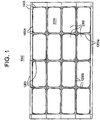
- Figure 1 is an illustration of a preform sheet that is laser perforated according to embodiment methods to facilitate molding of glass parts with small radii of curvature. More specifically, Figure 1 illustrates a top view of a preform sheet, in this case a large glass sheet 1000, that contains a plurality of multiple parts corresponding to pre-cut or pre-processed areas (parts) 2000, each of which will correspond to a single glass article 2000A.
- the sheet 1000 is laser perforated (defect lines are created) according to embodiment methods to facilitate molding of glass parts with small radii of curvature.
- release lines 12 are laser perforated according to methods disclosed above to facilitate singulation of individual part preforms 2000 into individual parts 2000A.
- the glass sheet 1000 contains twelve areas 2000 which are surrounded by perforations 1200A.
- Part outlines 1200B are also laser perforated to facilitate subsequent removal of parts from singulated preforms before, or following molding of the glass parts 20 to have 3D curved surfaces. It should be noted that in some embodiments, molding occurs with the entire preform sheet 1000 intact.
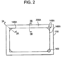
- Figure 2 is an illustration of one singulated preform separated from the sheet illustrated in Figure 1 . More specifically, Figure 2 illustrates a singulated glass blank 2000A, that includes bend area perforations 14A. Also illustrated in Figure. 2 are the corners 1400B of the part, which are laser perforated multiple times to facilitate molding the corners with small radii of curvature, as further described hereinafter in connection with the corner section view of Figure 3A through Figure 4B . Not shown in Figure 2 are other laser perforations that facilitate molding further 3D curvature on the surface of the glass part 2000A as further described hereinafter in connection with the side section view of Figures 4A and 4B .
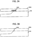
- Figures 3A -3B are side section views of the singulated preform of Figure 2 before and after, respectively, forming a 3D surface with a radius enabled by a laser perforation.
- Figure 3A illustrates the mold 1300, which has a 3D curved surface that defines 3D curvature to be applied to the surface of the part in the singulated preform (part 2000A ).
- the preform 2000A includes laser perforations 1400A that facilitate bending of the preform 2000A while inducing fewer or no surface defects.
- Figure 3B illustrates the same mold 1300 and preform 20A following molding, and it can be seen that the perforation 1400A relieves bending stresses in the glass. Such laser perforations can reduce or eliminate the need for vacuum or pressure application to the preform to complete the molding.
- Figures. 3A-B are side section views of the singulated preform of Figure 2 before and after forming a 3D surface with a radius enabled by a laser perforation (defect line). More specifically, Figures 3A and 3B illustrate two views of the perforated /singulated glass blank 2000A situated over a mold body 1300. The perforations 14A are situated over the areas where the glass blank 2000A will be bend. Note that the glass areas containing high density of perforations 1400A are situated near the areas of the mold of changing height and slope. These higher density perforated areas may correspond, for example, to the article corners, but may correspond to other features in the final glass article.
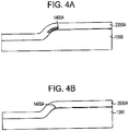
- Figures 4A and 4B are corner section views of the singulated preform of Figure 2 before and after forming a surface with a small corner radius enabled by multiple laser perforations (defect lines). More specifically, Figures 4A and 4B illustrate two views of the bent glass article formed from a singulated and perforated /singulated glass blank 2000A situated over a mold body 1300. The perforated /singulated glass blank 20A is bent over the mold 1300, with the densely perforated areas containing perforations 1400A and being directly situated over the areas of the mold with the corresponding change of height and/or slope.
- Figures 4A -4B are corner section views of the singulated preform of Figure 2 before and after, respectively, forming a surface with a small corner radius enabled by multiple laser perforations 1400A.
- particularly small radii of surface curvature such as 5 mm or 2 mm or less, for example, can be enabled by multiple perforations.
- the multiple or higher-density perforations result in stress relief during molding, diminished need for vacuum or pressure application during molding, and reduced surface defects.
- a glass article formed by the method(s) described herein comprises a curved surface or at least one non-flat surface, the article having a plurality of defect lines or perforations extending at least 200 microns (e.g. 250 microns or more) within said curved surface or said at least one non-flat surface, the defect lines each having a diameter less than or equal to about 5 microns.
- the spacing of adjacent defect lines is between 7 micron and 50 microns.
- the glass around said defect lines has subsurface damage up to a depth less than or equal to about 100 microns.
- the glass Article has a thickness between about 10 microns and about 5 mm.
- a laser can be used to create highly controlled full or partial perforations through the material (for example, in a single pass,), with extremely little ( ⁇ 75 ⁇ m, often ⁇ 50 ⁇ m) subsurface damage and debris generation.
- Sub-surface damage may be limited to the order of 100 ⁇ m in depth or less, or 75 ⁇ m in depth or less, or 60 ⁇ m in depth or less, or 50 ⁇ m in depth or less, and the cuts may produce only low debris.
- This method can be can be used for material perforation (e.g., glass perforation) in contrast to the typical use of spot-focused laser to ablate material, where multiple passes are often necessary to completely perforate the glass thickness, large amounts of debris are formed from the ablation process, and more extensive sub-surface damage (>100 ⁇ m) and edge chipping occur.
- material perforation e.g., glass perforation
- spot-focused laser to ablate material where multiple passes are often necessary to completely perforate the glass thickness, large amounts of debris are formed from the ablation process, and more extensive sub-surface damage (>100 ⁇ m) and edge chipping occur.
- defect lines also referred to herein as perforations, holes, or damage tracks
- the defect lines, or perforations, or fault lines represent regions of the substrate material modified by the laser.
- the laser-induced modifications disrupt the structure of the substrate material and constitute sites of mechanical weakness. Structural disruptions include compaction, melting, dislodging of material, rearrangements, and bond scission.
- the perforations extend into the interior of the substrate material and have a cross-sectional shape consistent with the cross-sectional shape of the laser (generally circular).
- the average diameter of the perforations may be in the range from 0.1 ⁇ m to 50 ⁇ m, or in the range from 1 ⁇ m to 20 ⁇ m, or in the range from 2 ⁇ m to 10 ⁇ m, or in the range from 0.1 ⁇ m to 5 ⁇ m.
- the perforation is a "through hole", which is a hole or an open channel that extends from the top to the bottom of the substrate material.
- the perforation may not be a continuously open channel and may include sections of solid material dislodged from the substrate material by the laser.
- the dislodged material blocks or partially blocks the space defined by the perforation.
- One or more open channels may be dispersed between sections of dislodged material.
- the diameter of the open channels is may be ⁇ 1000 nm, or ⁇ 500 nm, or ⁇ 400 nm, or ⁇ 300 nm or in the range from 10 nm to 750 nm, or in the range from 100 nm to 500 nm.
- the disrupted or modified area (e.g., compacted, melted, or otherwise changed) of the material surrounding the holes in the embodiments disclosed herein, preferably has diameter of ⁇ 50 ⁇ m (e.g., ⁇ 10 ⁇ m).
- the individual perforations can be created at rates of several hundred kilohertz (several hundred thousand perforations per second, for example).
- these perforations can be placed adjacent to one another with spatial separations varying from sub-micron to several or even tens of microns as desired.
- Distance between adjacent defect lines along the direction of the fault lines can, for example, be in range from 0.25 ⁇ m to 50 ⁇ m, or in the range from 0.50 ⁇ m to about 20 ⁇ m, or in the range from 0.50 ⁇ m to about 15 ⁇ m, or in the range from 0.50 ⁇ m to 10 ⁇ m, or in the range from 0.50 ⁇ m to 3.0 ⁇ m or in the range from 3.0 ⁇ m to 10 ⁇ m.
- the spatial separation is selected in order to facilitate weakening of the glass along the perforated contours, or cutting.
- MPA multi-photon absorption
- the excited state may be an excited electronic state or an ionized state.
- the energy difference between the higher and lower energy states of the material is equal to the sum of the energies of the two or more photons.
- MPA is a nonlinear process that is generally several orders of magnitude weaker than linear absorption.
- MPA It differs from linear absorption in that the strength of MPA depends on the square or higher power of the light intensity, thus making it a nonlinear optical process. At ordinary light intensities, MPA is negligible. If the light intensity (energy density) is extremely high, such as in the region of focus of a laser source (particularly a pulsed laser source), MPA becomes appreciable and leads to measurable effects in the material within the region where the energy density of the light source is sufficiently high. Within the focal region, the energy density may be sufficiently high to result in ionization.
- the ionization of individual atoms has discrete energy requirements.
- Several elements commonly used in glass e.g., Si, Na, K
- MPA ionization or excitation between states separated in energy by -5 eV can be accomplished with wavelengths longer than 248 nm.
- photons with a wavelength of 532 nm have an energy of ⁇ 2.33 eV, so two photons with wavelength 532 nm can induce a transition between states separated in energy by ⁇ 4.66 eV in two-photon absorption (TPA), for example.
- TPA two-photon absorption
- atoms and bonds can be selectively excited or ionized in the regions of a material where the energy density of the laser beam is sufficiently high to induce nonlinear TPA of a laser wavelength having half the required excitation energy, for example.
- MPA can result in a local reconfiguration and separation of the excited atoms or bonds from adjacent atoms or bonds.
- the resulting modification in the bonding or configuration can result in non-thermal ablation and removal of matter from the region of the material in which MPA occurs.
- This removal of matter creates a structural defect (the defect line, damage line, or perforation referred to hereinabove) that mechanically weakens the material and renders it more susceptible to cracking or fracturing upon application of mechanical or thermal stress.
- a contour or path along which cracking occurs can be precisely defined and precise micromachining of the material can be accomplished.
- the contour defined by a series of perforations may be regarded as a fault line and corresponds to a region of structural weakness in the material.
- the fault line defines the preferred contour for bending, or for separation of a part from the material and controls the shape of the separated part.
- micromachining includes separation of a part from the material processed by the laser, where the part has a precisely defined shape or perimeter determined by a fault line defining a closed contour of perforations formed through MPA effects induced by the laser.
- the glass perforated parts processed by the laser is bent to a tight radiys (e.g., 1mm to 5mm), where the part has a precisely defined shape or perimeter determined by a fault line defining a closed contour of perforations formed through MPA effects induced by the laser.
- the term closed contour refers to a perforation path formed by the laser line, where the path intersects with itself at some location.
- An internal contour is a path formed where the resulting shape is entirely surrounded by an outer portion of material.
- the preferred laser is an ultrashort pulsed laser (pulse durations on the order of 100 picoseconds or shorter) and can be operated in pulse mode or burst mode.
- pulse mode a series of nominally identical single pulses is emitted from the laser and directed to the workpiece.
- pulse mode the repetition rate of the laser is determined by the spacing in time between the pulses.
- burst mode bursts of pulses are emitted from the laser, where each burst includes two or more pulses (of equal or different amplitude).
- time interval refers to the time difference between corresponding parts of a pulse or burst (e.g. leading edge-to-leading edge, peak-to-peak, or trailing edge-to-trailing edge).
- Pulse and burst repetition rates are controlled by the design of the laser and can typically be adjusted, within limits, by adjusting operating conditions of the laser. Typical pulse and burst repetition rates are in the kHz to MHz range.
- the laser pulse duration (in pulse mode or for pulses within a burst in burst mode) may be 10 -10 s or less, or 10 -11 s or less, or 10 -12 s or less, or 10 -13 s or less. In the exemplary embodiments described herein, the laser pulse duration is greater than 10 -15 .
- One feature of embodiment processes is the high aspect ratio of defect lines created by an ultra-short pulsed laser.
- the high aspect ratio allows creation of a defect line that extends from the top surface to the bottom surface of the substrate material.
- the present methods also permit formation of defect lines that extend to a controlled depth within the substrate material.
- the defect line can be created by a single pulse or single burst of pulses, and, if desired, additional pulses or bursts can be used to increase the extension of the affected area (e.g., depth and width).
- the generation of a line focus may be performed by sending a Gaussian laser beam into an axicon lens, in which case a beam profile known as a Gauss-Bessel beam is created.
- a beam profile known as a Gauss-Bessel beam is created.
- Such a beam diffracts much more slowly (e.g. may maintain single micron spot sizes for ranges of hundreds of microns or millimeters as opposed to few tens of microns or less) than a Gaussian beam.
- the depth of focus or length of intense interaction with the material may be much larger than when using a Gaussian beam only.
- Other forms or slowly diffracting or non-diffracting beams may also be used, such as Airy beams.
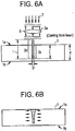
- an exemplary embodiment of method to perforate glass sheet(s) is based on creating a fault line or exemplary contour 110 (e.g., 1200 ) formed of a plurality of vertical defect lines 120 (corresponding for example, to perforations 1200A ) in the substrate material 130 (e.g., glass sheet 1000 ) with an ultra-short pulsed laser beam 140.
- a fault line or exemplary contour 110 e.g., 1200
- vertical defect lines 120 corresponding for example, to perforations 1200A
- Figure 5B illustrates an edge of a workpiece after separating the workpiece along the contour or fault line 110 defined by the multiple vertical defect lines 120 .
- the induced absorption creating the defect lines can produce particles on the separated edge or surface with an average particle diameter of less than 1 micron (for example 0.1 micron or smaller), resulting in a very clean process.
- Figure 5C is a picture showing an edge of an exemplary part (e.g., a singulated glass blank 2000A ) separated from the larger glass sheet using the laser process illustrated in Figure 5A and further described hereinafter.
- the created fault lines in a glass sheets may be different from one another- for example, the defect lines 120 (or holes) may be spaced closer in the contours along which one wants the glass to separate, and further apart in the areas when glass will be bent, but where one wants to avoid spontaneous separation.
- the exact pitch or separation between defect lines or perforations will be determined by the glass composition, but will typically be within the ranges described herein, for example from about 1 ⁇ m to about 25 ⁇ m.
- the areas that will be bend or curved have 10 or more holes (perforations) or defect lines per mm 2 , for example 10-100 holes, defect lines, or perforations 1400A per mm 2 .
- the areas that will be bend have at least 10 and preferably 20 or more holes or defect lines in area(s) that will be curved or bent, for example 25 or more holes, defect lines, or perforations 1400A per area (e.g., 25-500 holes, fault lines, or perforations, or 50-100, or 50-200 holes, fault lines, or perforations).
- the large number of holes facilitates bending.
- a small corner of the glass piece that needs to be bend may contain 20-50, or more holes or perforations.
- the number of holes or perforations will depend on the size of the glass area that will be bend or curved.
- the perforations or wholes are separated by 7 to 100 microns (i.e., the pitch may be 7-100 microns, for example 15 to 100 micron, 25 to 100 micron, or 25 to 50 micron), and the holes, fault lines, or perforations 1400A are less than 5 microns in diameter, and in some embodiments 3 microns or less in diameter, in some exemplary embodiments 2 micron or less) in diameter (e.g., 0.2 ⁇ m, 0.3 ⁇ m, 0.4 ⁇ m, 0.5 ⁇ m, 0.6 ⁇ m, 0.7 ⁇ m, 0.8 ⁇ m, 1 ⁇ m, 1.2 ⁇ m, 1.5 ⁇ m, or therebetween).
- the number of perforations in these areas may be, for example 10 to 50 or 10 to 30 per mm 2 area.
- the fault lines or perforations are formed by a laser beam, produced by a pulse burst laser, where the laser powers 10W to 100w (e.g., 25 W to 60 W) and the bursts contain at least 2 pulses, (e.g., 2-25 pulses)
- the created fault line is not enough to separate the part from the substrate material spontaneously, and a secondary step may be necessary for the separation of the glass (i.e., for singulation of parts from a larger sheet).
- a second laser can be used to create thermal stress to separate glass parts from each other.
- glass separation can be achieved after the creation of a defect line, for example, by application of mechanical force or by using a thermal source (e.g., an infrared laser, for example a CO 2 laser) to create thermal stress and force separation of the part from the substrate material along the fault line.
- an infrared laser to initiate the separation, and then finish the glass part separation manually.
- the optional infrared laser separation can be achieved with a focused continuous wave (cw) laser emitting at 10.6 microns and with power adjusted by controlling its duty cycle.
- Focus change i.e., extent of defocusing up to and including focused spot size
- Defocused laser beams include those laser beams that produce a spot size larger than a minimum, diffraction-limited spot size on the order of the size of the laser wavelength.
- defocused spot sizes (1/e 2 diameter) of 2 mm to 20 mm, or 2 mm to 12 mm, or about 7 mm, or about 2 mm and or about 20 mm can be used for CO 2 lasers, for example, whose diffraction-limited spot size is much smaller given the emission wavelength of 10.6 microns.
- the optical method of forming the focal line or line focus can take multiple forms, using donut shaped laser beams and spherical lenses, axicon lenses, diffractive elements, or other methods to form the linear region of high intensity.
- the type of laser (picosecond, femtosecond, etc.) and wavelength (IR, green, UV, etc.) can also be varied, as long as sufficient optical intensities are reached to create breakdown of the substrate or workpiece material in the region of focus to create breakdown of the substrate material through nonlinear optical effects (e.g., nonlinear absorption, multi-photon absorption).
- an ultra-short pulsed laser is used to create a high aspect ratio vertical defect line in a consistent, controllable and repeatable manner.
- the details of the optical setup that enables the creation of this vertical defect line are described below and in U.S. Application No. 14/154,525 filed on January 14, 2014 , the entire contents of which are incorporated by reference as if fully set forth herein.
- the essence of this concept is to use an axicon lens element in an optical lens assembly to create a region of high aspect ratio taper-free microchannels using ultra-short (picoseconds or femtosecond duration) Bessel beams.
- the axicon condenses the laser beam into a high intensity region of cylindrical shape and high aspect ratio (long length and small diameter) in the substrate material. Due to the high intensity created with the condensed laser beam, nonlinear interaction of the electromagnetic field of the laser and the substrate material occurs and the laser energy is transferred to the substrate to effect formation of defects that become constituents of the fault line.
- the substrate is transparent to the laser and there is no mechanism for transferring energy from the laser to the substrate. As a result, nothing happens to the substrate when the laser intensity is below the nonlinear threshold.
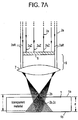
- a method of laser processing a material includes focusing a pulsed laser beam 2 into a laser beam focal line 2b, viewed along the beam propagation direction.
- Laser beam focal line 2b can be created by several ways, for example, Bessel beams, Airy beams, Weber beams and Mathieu beams (i.e., non-diffractive beams), whose field profiles are typically given by special functions that decay more slowly in the transverse direction (i.e. direction of propagation) than the Gaussian function.
- laser 3 (not shown) emits laser beam 2, which has a portion 2a incident to optical assembly 6.
- the optical assembly 6 turns the incident laser beam into laser beam focal line 2b on the output side over a defined expansion range along the beam direction (length 1 of the focal line).
- the planar substrate 1 (material to be processed) is positioned in the beam path to at least partially overlap the laser beam focal line 2b of laser beam 2.
- Reference la designates the surface of the planar substrate facing the optical assembly 6 or the laser, respectively, and reference 1b designates the reverse (remote) surface of substrate 1.
- the substrate thickness (measured perpendicularly to the planes 1a and 1b, i.e., to the substrate plane) is labeled with d.
- substrate 1 e.g., a glass sheet 1000
- the substrate is aligned substantially perpendicularly to the longitudinal beam axis and thus behind the same focal line 2b produced by the optical assembly 6 (the substrate is perpendicular to the plane of the drawing) Viewed along the beam direction, the substrate is positioned relative to the focal line 2b in such a way that the focal line 2b starts before the surface 1a of the substrate and stops before the surface 1b of the substrate, i.e. focal line 2b terminates within the substrate and does not extend beyond surface 1b.
- the focal line 2b starts before the surface 1a of the substrate and stops before the surface 1b of the substrate, i.e. focal line 2b terminates within the substrate and does not extend beyond surface 1b.
- the laser beam focal line 2b generates (assuming suitable laser intensity along the laser beam focal line 2b, which intensity is ensured by the focusing of laser beam 2 on a section of length 1 (i.e. a line focus of length 1)), which defines a section 2c (aligned along the longitudinal beam direction) along which an induced nonlinear absorption is generated in the substrate material.
- the induced absorption induces defect line formation in the substrate material along section 2c.
- the formation of defect lines is not only local, but extends over the entire length of the section 2c of the induced absorption.
- the length of section 2c (which corresponds to the length of the overlapping of laser beam focal line 2b with substrate 1) is labeled with reference L.
- the average diameter or the average dimension (extent (e.g. length or other relevant linear dimension)) of the section of the induced absorption 2c (or the sections in the material of substrate 1 undergoing formation of defect lines) is labeled with reference D.
- the average dimension D basically corresponds to the average diameter ⁇ of the laser beam focal line 2b, that is, an average spot diameter in a range of between about 0.1 microns and about 5 microns.
- the substrate material (which is transparent to the wavelength ⁇ of laser beam 2) is locally heated due to the induced absorption along the focal line 2b.
- This wavelength may be, for example, 1064, 532, 355 or 266 nanometers.
- the induced absorption arises from the nonlinear effects (e.g. two-photon absorption, multi-photon absorption) associated with the high intensity of the laser beam within focal line 2b.
- Figure 6B illustrates that the heated substrate material will eventually expand so that a correspondingly induced tension leads defect line formation, with the tension being the highest at surface la and to the desired amount micro-cracking required for separation, when needed.
- optical assemblies 6, which can be applied to generate the focal line 2b, as well as a representative optical setup, in which these optical assemblies can be applied, are described below. All assemblies or setups are based on the description above so that identical references are used for identical components or features or those which are equal in their function. Therefore only the differences are described below.
- the individual focal lines positioned on the substrate surface along the line of perforation, separation or detachment should be generated using the optical assembly described below (hereinafter, the optical assembly is alternatively also referred to as laser optics).
- the roughness of the separated surface (or cut edge) is determined primarily from the spot size or the spot diameter of the focal line. Roughness of a cut (separated) surface can be characterized, for example, by an Ra surface roughness parameter defined by the ASME B46.1 standard.
- Ra is the arithmetic average of the absolute values of the surface profile height deviations from the mean line, recorded within the evaluation length.
- Ra is the average of a set of absolute height deviations of individual features (peaks and valleys) of the surface relative to the mean.
- the optics In order to achieve a small spot size of, for example, 0.5 microns to 2 microns for a given wavelength ⁇ of the laser 3 that interacts with the material of substrate 1, certain requirements must usually be imposed on the numerical aperture of laser optics 6. These requirements are met by laser optics 6 described below.
- the laser beam must illuminate the optics up to the required aperture, which is typically achieved by means of beam widening using widening telescopes between the laser and focusing optics.
- the spot size should not vary too strongly for the purpose of a uniform interaction along the focal line. This can, for example, be ensured (see the embodiment below) by illuminating the focusing optics only in a small, circular area so that the beam opening and thus the percentage of the numerical aperture only vary slightly.
- the diameter of aperture 8 is selected in such a way that the beam bundles near the center of beam bundle 2a or the central beam (here labeled with 2aZ) hit the aperture and are completely absorbed by it. Only the beams in the outer perimeter range of beam bundle 2a (marginal rays, here labeled with 2aR) are not absorbed due to the reduced aperture size compared to the beam diameter, but pass aperture 8 laterally and hit the marginal areas of the focusing optic elements of the optical assembly 6, which, in this embodiment, is designed as a spherically cut, bi-convex lens 7.
- the laser beam focal line 2b is not only a single focal point for the laser beam, but rather a series of focal points for different rays in the laser beam.
- the series of focal points form an elongated focal line of a defined length, shown in Figure 7A as the length 1 of the laser beam focal line 2b.
- Lens 7 is centered on the central beam and is designed as a non-corrected, bi-convex focusing lens in the form of a common, spherically cut lens. The spherical aberration of such a lens may be advantageous.
- aspheres or multi-lens systems deviating from ideally corrected systems which do not form an ideal focal point but a distinct, elongated focal line of a defined length, can also be used (i.e., lenses or systems which do not have a single focal point).
- the zones of the lens thus focus along a focal line 2b, subject to the distance from the lens center.
- the diameter of aperture 8 across the beam direction is approximately 90% of the diameter of the beam bundle (defined by the distance required for the intensity of the beam to decrease to 1/e 2 of the peak intensity) and approximately 75% of the diameter of the lens 7 of the optical assembly 6.
- FIG. 7A shows the section in one plane through the central beam, and the complete three-dimensional bundle can be seen when the depicted beams are rotated around the focal line 2b.
- One potential disadvantage of the type of a focal line formed by lens 7 and the system shown in Figure 7A is that the conditions (spot size, laser intensity) may vary along the focal line (and thus along the desired depth in the material) and therefore the desired type of interaction (no melting, induced absorption, thermal-plastic deformation up to crack formation) may possibly occur only in selected portions of the focal line.
- the substrate material e.g., glass sheet 1000
- the efficiency of the process may be impaired, and the laser light may also be transmitted into undesired regions (e.g. parts or layers adherent to the substrate or the substrate holding fixture) and interact with them in an undesirable way (e.g., heating, diffusion, absorption, unwanted modification).
- Figure 7B-1-4 show (not only for the optical assembly in Figure 7A , but also for any other applicable optical assembly 6) that the position of laser beam focal line 2b can be controlled by suitably positioning and/or aligning the optical assembly 6 relative to substrate 1 as well as by suitably selecting the parameters of the optical assembly 6.
- the length 1 of the focal line 2b can be adjusted in such a way that it exceeds the substrate thickness d (here by factor 2). If substrate 1 (e.g., glass sheet 1000 ) is placed (viewed in longitudinal beam direction) centrally to focal line 2b, the section of induced absorption 2c is generated over the entire substrate thickness.
- the laser beam focal line 2b can have a length 1 in a range of between about 0.01 mm and about 100 mm, in a range of between about 0.1 mm and about 10 mm, or in a range of between about 0.1 mm and 1 mm, for example.
- Various embodiments can be configured to have length l of about 0.1 mm, 0.2 mm, 0.3 mm, 0.4 mm, 0.5 mm, 0.7 mm, 1 mm, 2 mm, 3 mm or 5 mm, for example.
- a focal line 2b of length 1 is generated which corresponds more or less to the substrate thickness d. Since substrate 1 is positioned relative to line 2b in such a way that line 2b starts at a point outside the substrate, the length L of the section of induced absorption 2c (which extends here from the substrate surface to a defined substrate depth, but not to the reverse (remote) surface 1b) is smaller than the length 1 of focal line 2b.
- Figure 7B-3 shows the case in which the substrate 1 (viewed along a direction perpendicular to the beam direction) is positioned above the starting point of focal line 2b so that the length 1 of line 2b is greater than the length L of the section of induced absorption 2c in substrate 1.
- focal line 2b it is particularly advantageous to position the focal line 2b in such a way that at least one of surfaces la, 1b is covered by the focal line, so that the section of induced absorption 2c starts at least on one surface of the substrate. In this way it is possible to achieve virtually ideal cuts while avoiding ablation, feathering and particulation at the surface.
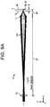
- Figure 8 depicts another applicable optical assembly 6.
- the basic construction follows the one described in Figure 7A so that only the differences are described below.
- the depicted optical assembly is based the use of optics with a non-spherical free surface in order to generate the focal line 2b, which is shaped in such a way that a focal line of defined length 1 is formed.
- aspheres can be used as optic elements of the optical assembly 6.
- a so-called conical prism also often referred to as axicon
- An axicon is a special, conically cut lens which forms a spot source on a line along the optical axis (or transforms a laser beam into a ring).
- the layout of such an axicon is generally known to one skilled in the art; the cone angle in the example is 10°.
- the apex of the axicon labeled here with reference 9 is directed towards the incidence direction and centered on the beam center. Since the focal line 2b produced by the axicon 9 starts within its interior, substrate 1 (here aligned perpendicularly to the main beam axis) can be positioned in the beam path directly behind axicon 9. As Figure 8 shows, it is also possible to shift substrate 1 along the beam direction due to the optical characteristics of the axicon while remaining within the range of focal line 2b. The section of the induced absorption 2c in the material of substrate 1 therefore extends over the entire substrate depth d.
- the depicted layout is subject to the following restrictions: Since the region of focal line 2b formed by axicon 9 begins within axicon 9, a significant part of the laser energy is not focused into the section of induced absorption 2c of focal line 2b, which is located within the material, in the situation where there is a separation between axicon 9 and the substrate material or workpiece. Furthermore, length 1 of focal line 2b is related to the beam diameter through the refractive indices and cone angles of axicon 9. This is why, in the case of relatively thin materials (several millimeters), the total focal line is much longer than the substrate thickness, having the effect that much of the laser energy is not focused into the material.
- Figure 9A depicts such an optical assembly 6 in which a first optical element with a non-spherical free surface designed to form an laser beam focal line 2b is positioned in the beam path of laser 3.
- this first optical element is an axicon 10 with a cone angle of 5°, which is positioned perpendicularly to the beam direction and centered on laser beam 3. The apex of the axicon is oriented towards the beam direction.
- a second, focusing optical element here the plano-convex lens 11 (the curvature of which is oriented towards the axicon), is positioned in the beam direction at a distance Z1 from the axicon 10.
- the distance Z1 in this case approximately 300 mm, is selected in such a way that the laser radiation formed by axicon 10 circularly incident on the outer radial portion of lens 11.
- Lens 11 focuses the circular radiation on the output side at a distance Z2, in this case approximately 20 mm from lens 11, on a focal line 2b of a defined length, in this case 1.5 mm.
- the effective focal length of lens 11 is 25 mm in this embodiment.
- the circular transformation of the laser beam by axicon 10 is labeled with the reference SR.
- Figure 9B depicts the formation of the focal line 2b or the induced absorption 2c in the material of substrate 1 according to Figure 9A in detail.
- the optical characteristics of both elements 10, 11 as well as the positioning of them is selected in such a way that the length 1 of the focal line 2b in beam direction is exactly identical with the thickness d of substrate 1. Consequently, an exact positioning of substrate 1 along the beam direction is required in order to position the focal line 2b exactly between the two surfaces 1a and 1b of substrate 1, as shown in Figure 9B .
- the focal line is formed at a certain distance from the laser optics, and if the greater part of the laser radiation is focused up to a desired end of the focal line.
- this can be achieved by illuminating a primarily focusing element 11 (lens) only circularly (annularly) over a particular outer radial region, which, on the one hand, serves to realize the required numerical aperture and thus the required spot size, and on the other hand, however, the circle of diffusion diminishes in intensity after the required focal line 2b over a very short distance in the center of the spot, as a basically circular spot is formed. In this way, the defect line formation is stopped within a short distance in the required substrate depth.
- a combination of axicon 10 and focusing lens 11 meets this requirement.
- the axicon acts in two different ways: due to the axicon 10, a usually round laser spot is sent to the focusing lens 11 in the form of a ring, and the asphericity of axicon 10 has the effect that a focal line is formed beyond the focal plane of the lens instead of a focal point in the focal plane.
- the length 1 of focal line 2b can be adjusted via the beam diameter on the axicon.
- the numerical aperture along the focal line on the other hand, can be adjusted via the distance Z1 (axicon-lens separation) and via the cone angle of the axicon. In this way, the entire laser energy can be concentrated in the focal line.
- the circular (annular) illumination still has the advantage that (1) the laser power is used optimally in the sense that most of the laser light remains concentrated in the required length of the focal line and (2) it is possible to achieve a uniform spot size along the focal line - and thus a uniform separation of part from substrate along the focal line - due to the circularly illuminated zone in conjunction with the desired aberration set by means of the other optical functions.
- both effects can be avoided by including another lens, a collimating lens 12 in the optical assembly 6.
- the additional positive lens 12 serves to adjust the circular illumination of focusing lens 11 very tightly.
- the focal length f of collimating lens 12 is selected in such a way that the desired circle diameter dr results from distance Zla from the axicon to the collimating lens 12, which is equal to f.
- the desired width br of the ring can be adjusted via the distance Zlb (collimating lens 12 to focusing lens 11).
- the small width of the circular illumination leads to a short focal line. A minimum can be achieved at distance f.
- the optical assembly 6 depicted in Figure 10 is thus based on the one depicted in Figure 9A so that only the differences are described below.
- the collimating lens 12, here also designed as a plano-convex lens (with its curvature towards the beam direction) is additionally placed centrally in the beam path between axicon 10 (with its apex towards the beam direction), on the one side, and the plano-convex lens 11, on the other side.
- the distance of collimating lens 12 from axicon 10 is referred to as Zla
- the distance of focusing lens 11 from collimating lens 12 as Zlb the distance of the focal line 2b from the focusing lens 11 as Z2 (always viewed in beam direction).
- the circular radiation SR formed by axicon 10 which is incident divergently and under the circle diameter dr on the collimating lens 12, is adjusted to the required circle width br along the distance Zlb for an at least approximately constant circle diameter dr at the focusing lens 11.
- a very short focal line 2b is intended to be generated so that the circle width br of approximately 4 mm at lens 12 is reduced to approximately 0.5 mm at lens 11 due to the focusing properties of lens 12 (circle diameter dr is 22 mm in the example).
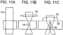
- Figures 11A -11C illustrate the laser-matter interaction at different laser intensity regimes.
- the unfocused laser beam 710 goes through a transparent substrate 720 without introducing any modification to it.
- the nonlinear effect is not present because the laser energy density (or laser energy per unit area illuminated by the beam) is below the threshold necessary to induce nonlinear effects.
- the beam waist of the focused laser is positioned at the surface of the substrate, modification of the surface will occur.
- the beam waist of the focused laser is positioned below the surface of the substrate, nothing happens at the surface when the energy density is below the threshold of the nonlinear optical effect. But at the focus 740, positioned in the bulk of the substrate 720, the laser intensity is high enough to trigger multi-photon non-linear effects, thus inducing damage to the material.
- the diffraction pattern of an axicon lens 750 creates interference that generates a Bessel-shaped intensity distribution (cylinder of high intensity 760) and only in that volume is the intensity high enough to create nonlinear absorption and modification to the material 720.
- the diameter of cylinder 760, in which Bessel-shaped intensity distribution is high enough to create nonlinear absorption and modification to the material, is also the spot diameter of the laser beam focal line, as referred to herein.
- one embodiment of the uses a 1064 nm picosecond pulsed laser in combination with line-focus beam forming optics to create lines of damage (also referred to herein as defect lines, damage tracks, or fault lines) in a Gorilla® glass substrate.
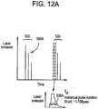
- the picosecond laser creates a "burst" 500 of pulses 500A, sometimes also called a "burst pulse". Bursting is a type of laser operation where the emission of pulses is not in a uniform and steady stream but rather in tight clusters of pulses.
- Each "burst" 500 may contain multiple pulses 500A (such as 2 pulses, 3 pulses, 4 pulses, 5 pulses, 10, 15, 20, or more) of very short duration T d up to 100 psec (for example, 0.1 psec, 5 psec, 10 psec, 15 psec, 18psec, 20 psec, 22 psec, 25 psec, 30 psec, 50 psec, 75 psec, or therebetween).
- the pulse duration is generally in a range from about 1 psec to about 1000 psec, or in a range from about 1 psec to about 100 psec, or in a range from about 2 psec to about 50 psec, or in a range from about 5 psec to about 20 psec.
- each pulse 500A within a single burst 500 can also be termed “sub-pulses,” which simply denotes the fact that they occur within a single burst of pulses.
- the energy or intensity of each laser pulse 500A within the burst may not be equal to that of other pulses within the burst, and the intensity distribution of the multiple pulses within a burst 500 may follow an exponential decay in time governed by the laser design.
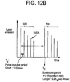
- each pulse 500A within the burst 500 of the exemplary embodiments described herein are separated in time from the subsequent pulse in the burst by a duration T p from 1 nsec to 50 nsec (e.g.
- each pulse is separated in time from the subsequent pulse by approximately 20 nsec (50 MHz pulse repetition frequency).
- the pulse-to-pulse separation T p within a burst is maintained within about ⁇ 10%, or is about ⁇ 2 nsec.
- the time between each "burst” (i.e., time separation T b between bursts) will be much longer (e.g., 0.25 ⁇ T b ⁇ 1000 microseconds, for example 1-10 microseconds, or 3-8 microseconds,)
- T b time separation
- the laser repetition rate is also referred to as burst repetition frequency or burst repetition rate herein, and is defined as the time between the first pulse in a burst to the first pulse in the subsequent burst.
- the burst repetition frequency is in a range of between about 1 kHz and about 4 MHz, or in a range between about 1 kHz and about 2 MHz, or in a range of between about 1 kHz and about 650 kHz, or in a range of between about 10 kHz and about 650 kHz.
- the time T b between the first pulse in each burst to the first pulse in the subsequent burst may be 0.25 microsecond (4MHz burst repetition rate) to 1000 microseconds (1 kHz burst repetition rate), for example 0.5 microseconds (2 MHz burst repetition rate) to 40 microseconds (25 kHz burst repetition rate), or 2 microseconds (500 kHz burst repetition rate) to 20 microseconds (50 kHz burst repetition rate).
- the exact timings, pulse durations, and repetition rates can vary depending on the laser design and user-controllable operating parameters. Short pulses (T d ⁇ 20 psec and preferably T d ⁇ 15 psec) of high intensity have been shown to work well.
- the required energy to modify the material can be described in terms of the burst energy - the energy contained within a burst (each burst 500 contains a series of pulses 500A), or in terms of the energy contained within a single laser pulse (many of which may comprise a burst).
- the energy per burst (per millimeter of the material to be cut) can be from 10-2500 ⁇ J, or from 20-1500 ⁇ J, or from 25-750 ⁇ J, or from 40-2500 ⁇ J, or from 100-1500 ⁇ J, or from 200-1250 ⁇ J, or from 250-1500 ⁇ J, or from 250-750 ⁇ J.
- the energy of an individual pulse within the burst will be less, and the exact individual laser pulse energy will depend on the number of pulses 500A within the burst 500 and the rate of decay (e.g., exponential decay rate) of the laser pulses with time as shown in Figure 12A and Figure 12B .
- the rate of decay e.g., exponential decay rate
- each individual laser pulse 500A will contain less energy than if the same burst pulse 500 had only 2 individual laser pulses.
- the use of lasers capable of generating such pulse bursts is advantageous for cutting, perforating, or modifying transparent materials, for example glass (e.g., glass sheets 1000 ).
- the use of a burst pulse sequence that spreads the laser energy over a rapid sequence of pulses within burst 500 allows access to larger timescales of high intensity interaction with the material than is possible with single-pulse lasers. While a single-pulse can be expanded in time, conservation of energy dictates that as this is done, the intensity within the pulse must drop as roughly one over the pulse width.
- the intensity during each pulse or sub-pulse 500A within the burst 500 can remain very high - for example three pulses 500A with pulse duration T d 10 psec that are spaced apart in time by a separation T p of approximately 10 nsec still allows the intensity within each pulse to be approximately three times higher than that of a single 10 psec pulse, while the laser is allowed to interact with the material over a timescale that is three orders of magnitude larger.
- This adjustment of multiple pulses 500A within a burst thus allows manipulation of timescale of the laser-material interaction in ways that can facilitate greater or lesser light interaction with a pre-existing plasma plume, greater or lesser light-material interaction with atoms and molecules that have been pre-excited by an initial or previous laser pulse, and greater or lesser heating effects within the material that can promote the controlled growth of defect lines (perforations).
- the amount of burst energy required to modify the material will depend on the substrate material composition and the length of the line focus used to interact with the substrate. The longer the interaction region, the more the energy is spread out, and the higher the burst energy that will be required.
- a defect line, a perforation, or a hole is formed in the material when a single burst of pulses strikes essentially the same location on the glass. That is, multiple laser pulses within a single burst can produce a single defect line, perforation, or a hole location in the glass.
- the individual pulses within the burst cannot be at exactly the same spatial location on the glass. However, they are well within 1 ⁇ m of one another-i.e., they strike the glass at essentially the same location. For example, they may strike the glass at a spacing sp where 0 ⁇ sp ⁇ 500 nm from one another.
- the individual pulses within the burst strike the glass within 250 nm of each other.
- a Corning glass code 2319 Gorilla® glass substrate 1000 with 0.55 mm thickness was positioned so that it was within the region of the focal line produced by the optical system.
- the optical intensities (energy densities) in the focal line region can easily be high enough to create non-linear absorption in the substrate material.
- a region of damaged, ablated, vaporized, or otherwise modified material within the substrate was created in the glass that approximately followed the linear region of high intensity.
- These damage tracks generally take the form of holes or perforations with interior dimensions (e.g. diameters) in the range of about 0.2 microns to 2 microns, for example 0.5-1.5 microns
- the holes or perforations are very small (single microns or less) in dimension.
- the defect lines, holes or perforations may or may not perforate the entire thickness of the material, and may or may not be a continuous opening throughout the depth of the material.
- Figure 5C shows an example of such tracks or defect lines perforating the entire thickness of a workpiece of 700 microns thick Gorilla® glass substrate (or glass sheet 1000).
- the perforations or damage tracks are observed through the side of a cleaved edge.
- the tracks through the material are not necessarily through holes. There are often regions of glass that plug the holes, but they are generally small in size, on the order of microns, for example.
- the lateral spacing (pitch) between the defect lines is determined by the pulse rate of the laser as the substrate is translated underneath the focused laser beam. Only a single picosecond laser pulse or burst is usually necessary to form an entire hole, but multiple pulses or bursts may be used if desired. To form holes or perforations at different pitches or defect line separations, the laser can be triggered to fire at longer or shorter intervals.
- the laser triggering generally is synchronized with the stage driven motion of the substrate beneath the beam, so laser pulses are triggered at a fixed interval, for example, every 1 microns, every 3 microns, or every 5 microns.
- the exact spacing between adjacent defect lines is determined by the material properties that facilitate crack propagation from perforated hole to perforated hole, given the stress level in the substrate.
- the holes may be separated by larger spacings (e.g., a 7 micron pitch, 8 micron pitch, 10 micron pitch, 25 micron pitch, 30 pitch, 50 pitch or greater).
- the pitch for perforations may be smaller than 7 or even smaller than 5 microns.
- the laser power and lens focal length are particularly important parameters to ensure full penetration of the glass and low surface and sub-surface damage.
- the process(s) disclosed herein can perforate or cut glass at a perforation or cutting speed of 0.25 m/sec, or faster.
- a perforation speed or cut speed (or cutting speed) is the rate the laser beam moves relative to the surface of the substrate material (e.g., glass) while creating multiple defect lines holes.
- High speeds such as, for example 350 mm/sec, 400 mm/sec, 500 mm/sec, 750 mm/sec, 1 m/sec, 1.2 m/sec, 1.5 m/sec, or 2 m/sec, or even 3.4 m/sec to 4 m/sec are often desired in order to minimize capital investment for manufacturing, and to optimize equipment utilization rate.
- the laser power is equal to the burst energy multiplied by the burst repetition frequency (rate) of the laser.
- the defect lines are typically spaced apart by 1-25 ⁇ m, in some embodiments the spacing is preferably 3 ⁇ m or larger- for example 3-12 ⁇ m, or for example 5-10 ⁇ m.
- a 3 ⁇ m hole pitch corresponds to a pulse burst laser with at least 100 kHz burst repetition rate.
- a 3 ⁇ m pitch corresponds to a burst-pulsed laser with at least 200 kHz burst repetition rate.
- a pulse burst laser that produces at least 40 ⁇ J/burst at 200 kHz, and perforates and/or cuts at a 600 mm/s cutting speed needs to have a laser power of at least 8 Watts. Higher perforation speed or higher cut speeds require accordingly higher laser powers.
- the laser power of the pulse burst picosecond laser is 6 W or higher, more preferably at least 8 W or higher, and even more preferably at least 10 W or higher.
- the optimal pitch between defect lines (damage tracks) and the exact burst energy is material dependent and can be determined empirically. However, in case of cauuting or glass separation, it should be noted that raising the laser pulse energy or making the damage tracks at a closer pitch are not conditions that always make the substrate material separate better or with improved edge quality.
- a pitch that is too small (for example ⁇ 0.1 micron, or in some exemplary embodiments ⁇ 1 ⁇ m, or in other embodiments ⁇ 2 ⁇ m) between defect lines (damage tracks) can sometimes inhibit the formation of nearby subsequent defect lines (damage tracks), and often can inhibit the separation of the material around the perforated contour. An increase in unwanted micro cracking within the glass may also result if the pitch is too small.
- a pitch that is too long e.g.
- microcracking may result in "uncontrolled microcracking" - i.e., where instead of propagating from defect line to defect line along the intended contour, the microcracks propagate along a different path, and cause the glass to crack in a different (undesirable) direction away from the intended contour. This may ultimately lower the strength of the separated part since the residual microcracks constitute flaws that weaken the glass.
- a burst energy for forming defect lines that is too high can cause "healing" or re-melting of previously formed defect lines, which may inhibit separation of the glass. Accordingly, it is preferred that the burst energy be ⁇ 2500 ⁇ J/burst, for example, ⁇ 500 ⁇ J/burst. Also, using a burst energy that is too high can cause formation of microcracks that are extremely large and create structural imperfections that can reduce the edge strength of the part after separation.
- a burst energy that is too low may result in no appreciable formation of defect lines within the glass, and hence may necessitate especially high separation force or result in a complete inability to separate along the perforated contour.
- Typical exemplary perforation speeds or cutting rates (speeds) enabled by this process are, for example, 0.25 m/sec and higher.
- the perforation speeds or cutting rates are at least 300 mm/sec.
- the cutting rates are at least 400 mm/sec, for example, 500 mm/sec to 2000 mm/sec, or higher.
- the picosecond (ps) laser utilizes pulse bursts to produce defect lines with periodicity between 0.5 ⁇ m and 13 ⁇ m, e.g. between 0.5 and 3 ⁇ m.
- the pulsed laser has laser power of 10 W - 100 W and the material (e.g.
- each pulse burst of the pulsed laser beam has an average laser energy measured at the workpiece (such as glass sheet 1000, for example) greater than 40 ⁇ J per burst per mm thickness of workpiece.
- each pulse burst of the pulsed laser beam has an average laser energy measured at the workpiece greater of less than 2500 ⁇ J per burst per mm thickness of workpiece, and preferably lass than about 2000 ⁇ J per burst per mm thickness of workpiece, and in some embodiments less than 1500 ⁇ J per burst per mm thickness of workpiece; for example, not more than 500 ⁇ J per burst per mm thickness of workpiece.
- volumetric pulse energy density ( ⁇ J/ ⁇ m 3 ) is required for perforating alkaline earth boroaluminosilicate glasses with low or no alkali content.
- This can be achieved, for example, by utilizing pulse burst lasers, preferably with at least 2 pulses per burst and providing volumetric energy densities within the alkaline earth boroaluminosilicate glasses (with low or no alkali) of about 0.05 ⁇ J/ ⁇ m 3 or higher, e.g., at least 0.1 ⁇ J/ ⁇ m 3 , for example 0.1-0.5 ⁇ J/ ⁇ m 3 .
- the laser produces pulse bursts with at least 2 pulses per burst.
- the pulsed laser has a power of 10 W-150 W (e.g., 10 W - 100 W) and produces pulse bursts with at least 2 pulses per burst (e.g., 2 - 25 pulses per burst).
- the pulsed laser has a power of 25 W-60 W, and produces pulse bursts with at least 2 -25 pulses per burst, and periodicity or distance between the adjacent defect lines produced by the laser bursts is 2-10 ⁇ m.
- the pulsed laser has a power of 10 W-100 W, produces pulse bursts with at least 2 pulses per burst, and the workpiece and the laser beam are translated relative to one another at a rate of at least 0.25 m/sec. In some embodiments the workpiece and/or the laser beam are translated relative to one another at a rate of at least 0.4 m/sec.
- pitches of 3-7 ⁇ m can work well, with pulse burst energies of about 150-250 ⁇ J/burst, and burst pulse numbers that range from 2-15, and preferably with pitches of 3-5 ⁇ m and burst pulse numbers (number of pulses per burst) of 2-5.
- the perforation and/or cutting of Eagle XG® glass or 2320 Gorilla®, glass typically requires utilization of laser powers of 15-84 W, with 30-45 W often being sufficient.
- laser powers between 10 W and 100W are preferred to achieve perforation and/or cutting speeds from 0.2-1 m/sec, with laser powers of 25-60 W being sufficient (or optimum) for many glasses.
- laser powers should preferably be 10 W-150 W, with burst energy of 40-750 ⁇ J/burst, 2-25 bursts per pulse (depending on the material that is cut), and defect line separation (pitch) of 3 to 15 ⁇ m, or 3-10 ⁇ m.
- burst energy 40-750 ⁇ J/burst
- bursts per pulse depending on the material that is cut
- defect line separation pitch
- picosecond pulse burst lasers would be preferable for these cutting speeds because they generate high power and the required number of pulses per burst.
- the pulsed laser produces 10 W - 100 W of power, for example 25 W to 60 W, and produces pulse bursts at least 2-25 pulses per burst and the distance between the defect lines is 2-15 ⁇ m; and the laser beam and/or workpiece are translated relative to one another at a rate of at least 0.25 m/sec, in some embodiments at least 0.4 m/sec, for example 0.5 m/sec to 5 m/sec, or faster.
- the laser perforation, or defect (hole) formation according some embodiments described herein was performed on both strengthened and unstrengthened glass.
- defocused CO 2 laser follows the picosecond laser as it traces the desired contour (fault line) to effect separation of the part from the surrounding substrate matrix.
- the thermal stress induced by the defocused CO 2 laser is enough to initiate and propagate cracks that lead to separation of the part along the desired contour defined by the fault line, thereby releasing the shaped part from the substrate panel.
- the best results were found for the following optics and laser parameters:
Landscapes
- Engineering & Computer Science (AREA)
- Chemical & Material Sciences (AREA)
- Physics & Mathematics (AREA)
- Optics & Photonics (AREA)
- Plasma & Fusion (AREA)
- Mechanical Engineering (AREA)
- Materials Engineering (AREA)
- Organic Chemistry (AREA)
- Chemical Kinetics & Catalysis (AREA)
- General Chemical & Material Sciences (AREA)
- Oil, Petroleum & Natural Gas (AREA)
- Laser Beam Processing (AREA)
- Re-Forming, After-Treatment, Cutting And Transporting Of Glass Products (AREA)
Claims (15)
- Verfahren zum Herstellen eines Glasartikels mit einem nicht-ebenen Abschnitt, wobei das Verfahren die folgenden Schritte umfasst:(i) Perforieren eines Glasrohlings entlang einer Kontur mit einem Laser und Formen mehrerer Perforationen (1400A) im Glasrohling, wobei die Perforationen Löcher oder Bereiche entfernten Festmaterials umfassen;(ii) Biegen des Glasrohlings entlang mindestens einer Perforationen (1400A) enthaltenden Fläche, so dass das Glas gekrümmt ist, Formen eines Glasartikels, der den nicht-ebenen Abschnitt aufweist.
- Verfahren zum Herstellen eines Glasartikels mit einem nicht-ebenen Abschnitt, wobei das Verfahren die folgenden Schritte umfasst:(i) Perforieren eines Glasrohlings entlang einer Kontur mit einem Laser und Formen mehrerer Perforationen (1400A) in mindestens einer Fläche in einem Glasrohling, wobei die Perforationen Löcher oder Bereiche entfernten Festmaterials umfassen und die Perforationen einen Durchmesser von unter 5 µm und eine Länge aufweisen, die mindestens 20-mal länger als der Durchmesser ist;(ii) Biegen des Glasrohlings entlang der mindestens einen Perforationen (1400A) enthaltenden Fläche, um den nicht-ebenen Abschnitt zu formen.
- Verfahren nach Anspruch 2, wobei die Perforationen:(i) einen Durchmesser von unter 2 µm und eine Länge aufweisen, die mindestens 50-mal länger als der Durchmesser ist; und/oder(ii) einen Durchmesser von unter 2 µm und die Länge aufweisen, die mindestens 200 µm lang ist.
- Verfahren nach einem der vorstehenden Ansprüche, wobei die mindestens eine Perforationen enthaltende Fläche mindestens 10 Perforationen je mm2 enthält.
- Verfahren nach einem der vorstehenden Ansprüche, wobei der Schritt des Perforierens mit Laserlinienfokus durchgeführt wird.
- Verfahren nach einem der vorstehenden Ansprüche, wobei das Biegen umfasst:(i) Erwärmen des Glasrohlings mit den Perforationen; und/oder(ii) Anlegen von Vakuum an die am wenigsten perforierten Flächen des Rohlings.
- Verfahren nach einem der vorstehenden Ansprüche, wobei der Glasrohling 0,1 mm bis 5 mm dick ist.
- Verfahren nach einem der vorstehenden Ansprüche, wobei das Biegen das Biegen des Glasrohlings in einen Krümmungsradius von 1 mm bis 10 mm umfasst.
- Verfahren nach einem der vorstehenden Ansprüche, wobei der Laser ein gepulster Laser ist, wobei der Laser eine Laserleistung von 10 W-100 W aufweist und Burstimpulse von mindestens 2 Impulsen je Burst erzeugt.
- Verfahren nach Anspruch 9, wobei (i) die Burstimpulse 2-25 Impulse je Burst enthalten; oder (ii) der gepulste Laser eine Laserleistung von 25 W-60 W aufweist und Burstimpulse von mindestens 2-25 Impulsen je Burst erzeugt und der Abstand zwischen den Fehlerlinien 7-100 Mikron ist.
- Verfahren des Verfahrens zum Herstellen eines Glasartikels mit nicht-ebenen Abschnitten nach Anspruch 1 oder 2, wobei der Schritt des Perforierens das Formen eines Laserlinienfokus zum Formen von Perforationen (1400A) enthält, wobei jede Perforation vom Laserstrahl mit ausreichender Intensität geformt wird, um die Struktur des Glases zu modifizieren, und mindestens eine Fläche mindestens 10 Perforationen je mm2 aufweist, wobei das Verfahren die folgenden Schritte umfasst:(A) Perforieren eines Glasbogens mit mehreren Glasrohlingen entsprechenden Flächen mit dem Laserlinienfokus, um mindestens eine perforierte Trennkontur zum Erzeugen mindestens eines Glasrohlings zu schaffen;(B) Trennen mindestens eines Glasrohlings vom Glasbogen entlang der perforierten Trennkontur, dadurch Erzeugen mindestens eines getrennten Glasrohlings (2000A).
- Verfahren zum Herstellen eines Glasartikels mit nicht-ebenen Abschnitten nach Anspruch 11, wobei das Biegen des Glasartikels die folgenden Schritte enthält:(A) Platzieren der getrennten Rohlinge über eine Form, so dass die mindestens eine Fläche, die die Perforationen (1400A) enthält, sich über der Fläche der Form befindet, die eine Änderung in der Höhe, Dicke oder Neigung aufweist;(B) Formen des Glasrohlings in den Glasartikel mit mindestens einem nicht-ebenen Abschnitt durch Biegen des Glasrohlings entlang mindestens einer Fläche, die die Perforationen (1400A) enthält, über der Form.
- Glasartikel mit mindestens einer nicht-ebenen Oberfläche, die durch das Verfahren nach einem der Ansprüche 1 bis 12 erhalten werden kann.
- Glasartikel nach Anspruch 13, wobei ein Abstand benachbarter Defektlinien zwischen 7 Mikron und 50 Mikron beträgt.
- Glasartikel nach Anspruch 13 oder 14, wobei:(i) das Glas einen Unteroberflächenschaden bis zu einer Tiefe von weniger oder gleich 100 Mikron aufweist;
und/oder(ii) das Glas eine Dicke von zwischen 10 Mikron und 5 mm aufweist.
Applications Claiming Priority (5)
| Application Number | Priority Date | Filing Date | Title |
|---|---|---|---|
| US201361917127P | 2013-12-17 | 2013-12-17 | |
| US14/154,525 US10421683B2 (en) | 2013-01-15 | 2014-01-14 | Method and device for the laser-based machining of sheet-like substrates |
| US201462024581P | 2014-07-15 | 2014-07-15 | |
| US201462024724P | 2014-07-15 | 2014-07-15 | |
| PCT/US2014/070724 WO2015095264A2 (en) | 2013-12-17 | 2014-12-17 | 3-d forming of glass |
Publications (2)
| Publication Number | Publication Date |
|---|---|
| EP3083514A2 EP3083514A2 (de) | 2016-10-26 |
| EP3083514B1 true EP3083514B1 (de) | 2019-03-06 |
Family
ID=53403875
Family Applications (1)
| Application Number | Title | Priority Date | Filing Date |
|---|---|---|---|
| EP14824690.3A Not-in-force EP3083514B1 (de) | 2013-12-17 | 2014-12-17 | 3d-glasherstellung und dazu gehörendem produkt |
Country Status (7)
| Country | Link |
|---|---|
| US (1) | US20160311717A1 (de) |
| EP (1) | EP3083514B1 (de) |
| JP (1) | JP6588911B2 (de) |
| KR (1) | KR20160100332A (de) |
| CN (1) | CN107241904B (de) |
| TW (1) | TWI653200B (de) |
| WO (1) | WO2015095264A2 (de) |
Families Citing this family (51)
| Publication number | Priority date | Publication date | Assignee | Title |
|---|---|---|---|---|
| JP6121901B2 (ja) | 2010-07-12 | 2017-04-26 | ロフィン−シナー テクノロジーズ インコーポレーテッド | レーザーフィラメント形成による材料加工方法 |
| EP2754524B1 (de) | 2013-01-15 | 2015-11-25 | Corning Laser Technologies GmbH | Verfahren und Vorrichtung zum laserbasierten Bearbeiten von flächigen Substraten, d.h. Wafer oder Glaselement, unter Verwendung einer Laserstrahlbrennlinie |
| EP2781296B1 (de) | 2013-03-21 | 2020-10-21 | Corning Laser Technologies GmbH | Vorrichtung und verfahren zum ausschneiden von konturen aus flächigen substraten mittels laser |
| US9102011B2 (en) | 2013-08-02 | 2015-08-11 | Rofin-Sinar Technologies Inc. | Method and apparatus for non-ablative, photoacoustic compression machining in transparent materials using filamentation by burst ultrafast laser pulses |
| US10017410B2 (en) | 2013-10-25 | 2018-07-10 | Rofin-Sinar Technologies Llc | Method of fabricating a glass magnetic hard drive disk platter using filamentation by burst ultrafast laser pulses |
| US10005152B2 (en) | 2013-11-19 | 2018-06-26 | Rofin-Sinar Technologies Llc | Method and apparatus for spiral cutting a glass tube using filamentation by burst ultrafast laser pulses |
| US9517929B2 (en) | 2013-11-19 | 2016-12-13 | Rofin-Sinar Technologies Inc. | Method of fabricating electromechanical microchips with a burst ultrafast laser pulses |
| US10252507B2 (en) | 2013-11-19 | 2019-04-09 | Rofin-Sinar Technologies Llc | Method and apparatus for forward deposition of material onto a substrate using burst ultrafast laser pulse energy |
| US11053156B2 (en) | 2013-11-19 | 2021-07-06 | Rofin-Sinar Technologies Llc | Method of closed form release for brittle materials using burst ultrafast laser pulses |
| US10144088B2 (en) | 2013-12-03 | 2018-12-04 | Rofin-Sinar Technologies Llc | Method and apparatus for laser processing of silicon by filamentation of burst ultrafast laser pulses |
| US9517963B2 (en) | 2013-12-17 | 2016-12-13 | Corning Incorporated | Method for rapid laser drilling of holes in glass and products made therefrom |
| US9815730B2 (en) | 2013-12-17 | 2017-11-14 | Corning Incorporated | Processing 3D shaped transparent brittle substrate |
| US11556039B2 (en) | 2013-12-17 | 2023-01-17 | Corning Incorporated | Electrochromic coated glass articles and methods for laser processing the same |
| US9938187B2 (en) | 2014-02-28 | 2018-04-10 | Rofin-Sinar Technologies Llc | Method and apparatus for material processing using multiple filamentation of burst ultrafast laser pulses |
| CN106687419A (zh) | 2014-07-08 | 2017-05-17 | 康宁股份有限公司 | 用于激光处理材料的方法和设备 |
| US11648623B2 (en) | 2014-07-14 | 2023-05-16 | Corning Incorporated | Systems and methods for processing transparent materials using adjustable laser beam focal lines |
| US9757815B2 (en) | 2014-07-21 | 2017-09-12 | Rofin-Sinar Technologies Inc. | Method and apparatus for performing laser curved filamentation within transparent materials |
| FR3024137B1 (fr) * | 2014-07-24 | 2016-07-29 | Saint Gobain | Procede de fabrication de feuilles de verre de forme complexe |
| CN104310779A (zh) * | 2014-09-29 | 2015-01-28 | 合肥鑫晟光电科技有限公司 | 一种激光切割基板的方法及激光切割设备 |
| EP3102358A4 (de) | 2015-01-13 | 2017-10-25 | Rofin-Sinar Technologies, Inc. | Verfahren und system zum ritzen von sprödem material nach chemischem ätzen |
| WO2016138054A1 (en) | 2015-02-27 | 2016-09-01 | Corning Incorporated | Optical assembly having microlouvers |
| HUE055461T2 (hu) | 2015-03-24 | 2021-11-29 | Corning Inc | Kijelzõ üveg kompozíciók lézeres vágása és feldolgozása |
| DE102015111490A1 (de) | 2015-07-15 | 2017-01-19 | Schott Ag | Verfahren und Vorrichtung zum lasergestützten Abtrennen eines Teilstücks von einem flächigen Glaselement |
| DE102015116848A1 (de) * | 2015-10-05 | 2017-04-06 | Schott Ag | Dielektrisches Werkstück mit einer Zone definiert ausgebildeter Festigkeit sowie Verfahren zu dessen Herstellung und dessen Verwendung |
| US10410883B2 (en) | 2016-06-01 | 2019-09-10 | Corning Incorporated | Articles and methods of forming vias in substrates |
| US10794679B2 (en) | 2016-06-29 | 2020-10-06 | Corning Incorporated | Method and system for measuring geometric parameters of through holes |
| WO2018022476A1 (en) * | 2016-07-29 | 2018-02-01 | Corning Incorporated | Apparatuses and methods for laser processing |
| CN109803786B (zh) | 2016-09-30 | 2021-05-07 | 康宁股份有限公司 | 使用非轴对称束斑对透明工件进行激光加工的设备和方法 |
| JP2018065188A (ja) * | 2016-10-21 | 2018-04-26 | 日本電気硝子株式会社 | レーザー加工方法 |
| US11542190B2 (en) | 2016-10-24 | 2023-01-03 | Corning Incorporated | Substrate processing station for laser-based machining of sheet-like glass substrates |
| US10580725B2 (en) | 2017-05-25 | 2020-03-03 | Corning Incorporated | Articles having vias with geometry attributes and methods for fabricating the same |
| US11078112B2 (en) | 2017-05-25 | 2021-08-03 | Corning Incorporated | Silica-containing substrates with vias having an axially variable sidewall taper and methods for forming the same |
| JP6981806B2 (ja) * | 2017-08-09 | 2021-12-17 | 株式会社ディスコ | 分割方法 |
| TW201919805A (zh) * | 2017-08-25 | 2019-06-01 | 美商康寧公司 | 使用遠焦光束調整組件以雷射處理透明工件的設備與方法 |
| US12180108B2 (en) | 2017-12-19 | 2024-12-31 | Corning Incorporated | Methods for etching vias in glass-based articles employing positive charge organic molecules |
| US11554984B2 (en) | 2018-02-22 | 2023-01-17 | Corning Incorporated | Alkali-free borosilicate glasses with low post-HF etch roughness |
| US12151962B2 (en) * | 2018-03-06 | 2024-11-26 | Corning Incorporated | Apparatus and method for controlling substrate thickness |
| US11059131B2 (en) | 2018-06-22 | 2021-07-13 | Corning Incorporated | Methods for laser processing a substrate stack having one or more transparent workpieces and a black matrix layer |
| TWI841629B (zh) * | 2018-11-29 | 2024-05-11 | 美商康寧公司 | 用於抬頭顯示系統之反曲率非球面鏡及其形成方法 |
| CN110732789A (zh) * | 2019-10-23 | 2020-01-31 | 中南大学 | 一种热辅助的飞秒激光加工方法 |
| KR102819808B1 (ko) * | 2020-06-15 | 2025-06-16 | 삼성디스플레이 주식회사 | 윈도우 성형 장치 및 이를 이용한 윈도우 성형 방법 |
| JP7451047B2 (ja) * | 2020-08-28 | 2024-03-18 | 株式会社ディスコ | 板状物の製造方法及び板状物 |
| WO2022047385A1 (en) * | 2020-08-31 | 2022-03-03 | The Cooper Group, Llc | Historically accurate simulated divided light glass unit and methods of making the same |
| CN114644448A (zh) * | 2020-12-21 | 2022-06-21 | 余姚舜宇智能光学技术有限公司 | 曲面玻璃和曲面玻璃的开孔方法 |
| JP7458511B2 (ja) * | 2021-01-28 | 2024-03-29 | Hoya株式会社 | ガラス板の製造方法、磁気ディスク用ガラス基板の製造方法、磁気ディスクの製造方法、およびガラス板の処理装置 |
| CN114477738A (zh) * | 2021-09-28 | 2022-05-13 | 新沂市铭达玻璃有限公司 | 一种汽车玻璃加工的热成型工艺 |
| CN114772940A (zh) * | 2022-05-25 | 2022-07-22 | 武汉理工大学 | 一种激光直写微纳结构制造可折叠玻璃的方法 |
| CN115448586A (zh) * | 2022-10-27 | 2022-12-09 | 芜湖东信光电科技有限公司 | 一种可折叠玻璃及其制备方法 |
| CN116040953A (zh) * | 2022-10-27 | 2023-05-02 | 芜湖东信光电科技有限公司 | 一种柔性可折叠玻璃及其制备方法 |
| CN119038861A (zh) * | 2024-08-19 | 2024-11-29 | 福耀玻璃工业集团股份有限公司 | 玻璃成型方法、玻璃及车辆 |
| CN119954378B (zh) * | 2025-04-11 | 2025-07-15 | 赣州明智达特种玻璃科技有限公司 | 一种适用于特种玻璃局部弯曲加工的玻璃成型模具 |
Family Cites Families (21)
| Publication number | Priority date | Publication date | Assignee | Title |
|---|---|---|---|---|
| JP2000327349A (ja) * | 1999-05-24 | 2000-11-28 | China Glaze Co Ltd | 結晶化ガラス板の曲げ加工方法 |
| KR100693934B1 (ko) * | 2006-03-24 | 2007-03-12 | 케이 이엔지(주) | 벤딩부가 장착된 유리절단 장치 및 이를 이용한 유리의절단방법 |
| DE102006035555A1 (de) * | 2006-07-27 | 2008-01-31 | Eliog-Kelvitherm Industrieofenbau Gmbh | Anordnung und Verfahren zur Verformung von Glasscheiben |
| US20100276505A1 (en) * | 2007-09-26 | 2010-11-04 | Roger Earl Smith | Drilling in stretched substrates |
| JP5096903B2 (ja) * | 2007-12-18 | 2012-12-12 | 国立大学法人埼玉大学 | ガラス箔の3次元加工方法 |
| JP6121901B2 (ja) * | 2010-07-12 | 2017-04-26 | ロフィン−シナー テクノロジーズ インコーポレーテッド | レーザーフィラメント形成による材料加工方法 |
| EP2457881B1 (de) * | 2010-11-30 | 2019-05-08 | Corning Incorporated | Verfahren und Vorrichtung zum Biegen einer Materialplatte in einen Formgegenstand |
| US20120151760A1 (en) * | 2010-12-15 | 2012-06-21 | Sony Ericsson Mobile Communications Ab | Non-planar display glass for mobile device |
| JP5906198B2 (ja) * | 2011-02-08 | 2016-04-20 | 株式会社フジクラ | 微細孔を有する基体の製造方法、及び基体 |
| CN103182894A (zh) * | 2011-12-29 | 2013-07-03 | 深圳富泰宏精密工业有限公司 | 玻璃件及其制作方法 |
| JPWO2013129165A1 (ja) * | 2012-02-27 | 2015-07-30 | 旭硝子株式会社 | ガラス基板を製造する方法、およびガラス基板 |
| JP2015511571A (ja) * | 2012-02-28 | 2015-04-20 | エレクトロ サイエンティフィック インダストリーズ インコーポレーテッド | 強化ガラスの分離のための方法及び装置並びにこれにより生成された製品 |
| WO2014079478A1 (en) * | 2012-11-20 | 2014-05-30 | Light In Light Srl | High speed laser processing of transparent materials |
| CN102962583A (zh) * | 2012-11-28 | 2013-03-13 | 江苏大学 | 一种基于激光加热的塑料件微结构成形方法和装置 |
| CN105246850B (zh) * | 2012-11-29 | 2018-01-30 | 康宁股份有限公司 | 通过激光损坏和蚀刻制造玻璃制品的方法 |
| US9102007B2 (en) * | 2013-08-02 | 2015-08-11 | Rofin-Sinar Technologies Inc. | Method and apparatus for performing laser filamentation within transparent materials |
| US11053156B2 (en) * | 2013-11-19 | 2021-07-06 | Rofin-Sinar Technologies Llc | Method of closed form release for brittle materials using burst ultrafast laser pulses |
| US9815730B2 (en) * | 2013-12-17 | 2017-11-14 | Corning Incorporated | Processing 3D shaped transparent brittle substrate |
| US9757815B2 (en) * | 2014-07-21 | 2017-09-12 | Rofin-Sinar Technologies Inc. | Method and apparatus for performing laser curved filamentation within transparent materials |
| DE102014110920C5 (de) * | 2014-07-31 | 2023-08-03 | Schott Ag | Geformter Glasartikel mit vorbestimmter Geometrie |
| KR20170006900A (ko) * | 2015-07-10 | 2017-01-18 | 삼성전자주식회사 | 성형장치 및 이를 이용한 성형방법 |
-
2014
- 2014-12-17 TW TW103144134A patent/TWI653200B/zh not_active IP Right Cessation
- 2014-12-17 CN CN201480075620.XA patent/CN107241904B/zh not_active Expired - Fee Related
- 2014-12-17 US US15/105,741 patent/US20160311717A1/en not_active Abandoned
- 2014-12-17 EP EP14824690.3A patent/EP3083514B1/de not_active Not-in-force
- 2014-12-17 JP JP2016541161A patent/JP6588911B2/ja not_active Expired - Fee Related
- 2014-12-17 KR KR1020167018781A patent/KR20160100332A/ko not_active Withdrawn
- 2014-12-17 WO PCT/US2014/070724 patent/WO2015095264A2/en not_active Ceased
Non-Patent Citations (1)
| Title |
|---|
| None * |
Also Published As
| Publication number | Publication date |
|---|---|
| TWI653200B (zh) | 2019-03-11 |
| JP6588911B2 (ja) | 2019-10-09 |
| CN107241904A (zh) | 2017-10-10 |
| WO2015095264A3 (en) | 2015-09-24 |
| WO2015095264A2 (en) | 2015-06-25 |
| CN107241904B (zh) | 2019-08-30 |
| EP3083514A2 (de) | 2016-10-26 |
| KR20160100332A (ko) | 2016-08-23 |
| TW201527234A (zh) | 2015-07-16 |
| JP2017504553A (ja) | 2017-02-09 |
| US20160311717A1 (en) | 2016-10-27 |
Similar Documents
| Publication | Publication Date | Title |
|---|---|---|
| EP3083514B1 (de) | 3d-glasherstellung und dazu gehörendem produkt | |
| US10392290B2 (en) | Processing 3D shaped transparent brittle substrate | |
| US10179748B2 (en) | Laser processing of sapphire substrate and related applications | |
| EP3511302B1 (de) | Laserbearbeitung von schlitzen und löchern | |
| US10183885B2 (en) | Laser cut composite glass article and method of cutting | |
| US10442719B2 (en) | Edge chamfering methods | |
| EP3083510A1 (de) | Laserschneiden von anzeigeglaszusammensetzungen anzeige |
Legal Events
| Date | Code | Title | Description |
|---|---|---|---|
| PUAI | Public reference made under article 153(3) epc to a published international application that has entered the european phase |
Free format text: ORIGINAL CODE: 0009012 |
|
| 17P | Request for examination filed |
Effective date: 20160714 |
|
| AK | Designated contracting states |
Kind code of ref document: A2 Designated state(s): AL AT BE BG CH CY CZ DE DK EE ES FI FR GB GR HR HU IE IS IT LI LT LU LV MC MK MT NL NO PL PT RO RS SE SI SK SM TR |
|
| AX | Request for extension of the european patent |
Extension state: BA ME |
|
| DAX | Request for extension of the european patent (deleted) | ||
| STAA | Information on the status of an ep patent application or granted ep patent |
Free format text: STATUS: EXAMINATION IS IN PROGRESS |
|
| 17Q | First examination report despatched |
Effective date: 20170419 |
|
| GRAP | Despatch of communication of intention to grant a patent |
Free format text: ORIGINAL CODE: EPIDOSNIGR1 |
|
| STAA | Information on the status of an ep patent application or granted ep patent |
Free format text: STATUS: GRANT OF PATENT IS INTENDED |
|
| RIC1 | Information provided on ipc code assigned before grant |
Ipc: B23K 26/0622 20140101ALI20180731BHEP Ipc: B23K 26/359 20140101ALI20180731BHEP Ipc: B23K 26/382 20140101ALI20180731BHEP Ipc: C03B 33/02 20060101AFI20180731BHEP Ipc: B23K 26/55 20140101ALI20180731BHEP Ipc: C03B 23/023 20060101ALI20180731BHEP Ipc: C03B 23/025 20060101ALI20180731BHEP Ipc: B23K 26/00 20140101ALI20180731BHEP Ipc: B23K 103/00 20060101ALI20180731BHEP Ipc: C03B 23/035 20060101ALI20180731BHEP Ipc: B23K 26/38 20140101ALI20180731BHEP Ipc: C03B 23/02 20060101ALI20180731BHEP Ipc: B23K 26/57 20140101ALI20180731BHEP |
|
| INTG | Intention to grant announced |
Effective date: 20180904 |
|
| GRAJ | Information related to disapproval of communication of intention to grant by the applicant or resumption of examination proceedings by the epo deleted |
Free format text: ORIGINAL CODE: EPIDOSDIGR1 |
|
| STAA | Information on the status of an ep patent application or granted ep patent |
Free format text: STATUS: EXAMINATION IS IN PROGRESS |
|
| GRAR | Information related to intention to grant a patent recorded |
Free format text: ORIGINAL CODE: EPIDOSNIGR71 |
|
| GRAS | Grant fee paid |
Free format text: ORIGINAL CODE: EPIDOSNIGR3 |
|
| STAA | Information on the status of an ep patent application or granted ep patent |
Free format text: STATUS: GRANT OF PATENT IS INTENDED |
|
| GRAA | (expected) grant |
Free format text: ORIGINAL CODE: 0009210 |
|
| STAA | Information on the status of an ep patent application or granted ep patent |
Free format text: STATUS: THE PATENT HAS BEEN GRANTED |
|
| INTC | Intention to grant announced (deleted) | ||
| INTG | Intention to grant announced |
Effective date: 20190124 |
|
| AK | Designated contracting states |
Kind code of ref document: B1 Designated state(s): AL AT BE BG CH CY CZ DE DK EE ES FI FR GB GR HR HU IE IS IT LI LT LU LV MC MK MT NL NO PL PT RO RS SE SI SK SM TR |
|
| REG | Reference to a national code |
Ref country code: GB Ref legal event code: FG4D |
|
| REG | Reference to a national code |
Ref country code: CH Ref legal event code: EP Ref country code: AT Ref legal event code: REF Ref document number: 1104303 Country of ref document: AT Kind code of ref document: T Effective date: 20190315 |
|
| REG | Reference to a national code |
Ref country code: DE Ref legal event code: R096 Ref document number: 602014042496 Country of ref document: DE |
|
| REG | Reference to a national code |
Ref country code: IE Ref legal event code: FG4D |
|
| REG | Reference to a national code |
Ref country code: NL Ref legal event code: MP Effective date: 20190306 |
|
| REG | Reference to a national code |
Ref country code: LT Ref legal event code: MG4D |
|
| PG25 | Lapsed in a contracting state [announced via postgrant information from national office to epo] |
Ref country code: NO Free format text: LAPSE BECAUSE OF FAILURE TO SUBMIT A TRANSLATION OF THE DESCRIPTION OR TO PAY THE FEE WITHIN THE PRESCRIBED TIME-LIMIT Effective date: 20190606 Ref country code: LT Free format text: LAPSE BECAUSE OF FAILURE TO SUBMIT A TRANSLATION OF THE DESCRIPTION OR TO PAY THE FEE WITHIN THE PRESCRIBED TIME-LIMIT Effective date: 20190306 Ref country code: SE Free format text: LAPSE BECAUSE OF FAILURE TO SUBMIT A TRANSLATION OF THE DESCRIPTION OR TO PAY THE FEE WITHIN THE PRESCRIBED TIME-LIMIT Effective date: 20190306 Ref country code: FI Free format text: LAPSE BECAUSE OF FAILURE TO SUBMIT A TRANSLATION OF THE DESCRIPTION OR TO PAY THE FEE WITHIN THE PRESCRIBED TIME-LIMIT Effective date: 20190306 |
|
| PG25 | Lapsed in a contracting state [announced via postgrant information from national office to epo] |
Ref country code: LV Free format text: LAPSE BECAUSE OF FAILURE TO SUBMIT A TRANSLATION OF THE DESCRIPTION OR TO PAY THE FEE WITHIN THE PRESCRIBED TIME-LIMIT Effective date: 20190306 Ref country code: RS Free format text: LAPSE BECAUSE OF FAILURE TO SUBMIT A TRANSLATION OF THE DESCRIPTION OR TO PAY THE FEE WITHIN THE PRESCRIBED TIME-LIMIT Effective date: 20190306 Ref country code: BG Free format text: LAPSE BECAUSE OF FAILURE TO SUBMIT A TRANSLATION OF THE DESCRIPTION OR TO PAY THE FEE WITHIN THE PRESCRIBED TIME-LIMIT Effective date: 20190606 Ref country code: GR Free format text: LAPSE BECAUSE OF FAILURE TO SUBMIT A TRANSLATION OF THE DESCRIPTION OR TO PAY THE FEE WITHIN THE PRESCRIBED TIME-LIMIT Effective date: 20190607 Ref country code: HR Free format text: LAPSE BECAUSE OF FAILURE TO SUBMIT A TRANSLATION OF THE DESCRIPTION OR TO PAY THE FEE WITHIN THE PRESCRIBED TIME-LIMIT Effective date: 20190306 Ref country code: NL Free format text: LAPSE BECAUSE OF FAILURE TO SUBMIT A TRANSLATION OF THE DESCRIPTION OR TO PAY THE FEE WITHIN THE PRESCRIBED TIME-LIMIT Effective date: 20190306 |
|
| REG | Reference to a national code |
Ref country code: AT Ref legal event code: MK05 Ref document number: 1104303 Country of ref document: AT Kind code of ref document: T Effective date: 20190306 |
|
| PG25 | Lapsed in a contracting state [announced via postgrant information from national office to epo] |
Ref country code: ES Free format text: LAPSE BECAUSE OF FAILURE TO SUBMIT A TRANSLATION OF THE DESCRIPTION OR TO PAY THE FEE WITHIN THE PRESCRIBED TIME-LIMIT Effective date: 20190306 Ref country code: AL Free format text: LAPSE BECAUSE OF FAILURE TO SUBMIT A TRANSLATION OF THE DESCRIPTION OR TO PAY THE FEE WITHIN THE PRESCRIBED TIME-LIMIT Effective date: 20190306 Ref country code: PT Free format text: LAPSE BECAUSE OF FAILURE TO SUBMIT A TRANSLATION OF THE DESCRIPTION OR TO PAY THE FEE WITHIN THE PRESCRIBED TIME-LIMIT Effective date: 20190706 Ref country code: IT Free format text: LAPSE BECAUSE OF FAILURE TO SUBMIT A TRANSLATION OF THE DESCRIPTION OR TO PAY THE FEE WITHIN THE PRESCRIBED TIME-LIMIT Effective date: 20190306 Ref country code: SK Free format text: LAPSE BECAUSE OF FAILURE TO SUBMIT A TRANSLATION OF THE DESCRIPTION OR TO PAY THE FEE WITHIN THE PRESCRIBED TIME-LIMIT Effective date: 20190306 Ref country code: RO Free format text: LAPSE BECAUSE OF FAILURE TO SUBMIT A TRANSLATION OF THE DESCRIPTION OR TO PAY THE FEE WITHIN THE PRESCRIBED TIME-LIMIT Effective date: 20190306 Ref country code: CZ Free format text: LAPSE BECAUSE OF FAILURE TO SUBMIT A TRANSLATION OF THE DESCRIPTION OR TO PAY THE FEE WITHIN THE PRESCRIBED TIME-LIMIT Effective date: 20190306 Ref country code: EE Free format text: LAPSE BECAUSE OF FAILURE TO SUBMIT A TRANSLATION OF THE DESCRIPTION OR TO PAY THE FEE WITHIN THE PRESCRIBED TIME-LIMIT Effective date: 20190306 |
|
| PG25 | Lapsed in a contracting state [announced via postgrant information from national office to epo] |
Ref country code: SM Free format text: LAPSE BECAUSE OF FAILURE TO SUBMIT A TRANSLATION OF THE DESCRIPTION OR TO PAY THE FEE WITHIN THE PRESCRIBED TIME-LIMIT Effective date: 20190306 Ref country code: PL Free format text: LAPSE BECAUSE OF FAILURE TO SUBMIT A TRANSLATION OF THE DESCRIPTION OR TO PAY THE FEE WITHIN THE PRESCRIBED TIME-LIMIT Effective date: 20190306 |
|
| REG | Reference to a national code |
Ref country code: DE Ref legal event code: R097 Ref document number: 602014042496 Country of ref document: DE |
|
| PG25 | Lapsed in a contracting state [announced via postgrant information from national office to epo] |
Ref country code: IS Free format text: LAPSE BECAUSE OF FAILURE TO SUBMIT A TRANSLATION OF THE DESCRIPTION OR TO PAY THE FEE WITHIN THE PRESCRIBED TIME-LIMIT Effective date: 20190706 Ref country code: AT Free format text: LAPSE BECAUSE OF FAILURE TO SUBMIT A TRANSLATION OF THE DESCRIPTION OR TO PAY THE FEE WITHIN THE PRESCRIBED TIME-LIMIT Effective date: 20190306 |
|
| PLBE | No opposition filed within time limit |
Free format text: ORIGINAL CODE: 0009261 |
|
| STAA | Information on the status of an ep patent application or granted ep patent |
Free format text: STATUS: NO OPPOSITION FILED WITHIN TIME LIMIT |
|
| PG25 | Lapsed in a contracting state [announced via postgrant information from national office to epo] |
Ref country code: DK Free format text: LAPSE BECAUSE OF FAILURE TO SUBMIT A TRANSLATION OF THE DESCRIPTION OR TO PAY THE FEE WITHIN THE PRESCRIBED TIME-LIMIT Effective date: 20190306 |
|
| PGFP | Annual fee paid to national office [announced via postgrant information from national office to epo] |
Ref country code: DE Payment date: 20191114 Year of fee payment: 6 |
|
| 26N | No opposition filed |
Effective date: 20191209 |
|
| PG25 | Lapsed in a contracting state [announced via postgrant information from national office to epo] |
Ref country code: SI Free format text: LAPSE BECAUSE OF FAILURE TO SUBMIT A TRANSLATION OF THE DESCRIPTION OR TO PAY THE FEE WITHIN THE PRESCRIBED TIME-LIMIT Effective date: 20190306 |
|
| PGFP | Annual fee paid to national office [announced via postgrant information from national office to epo] |
Ref country code: FR Payment date: 20191122 Year of fee payment: 6 |
|
| PG25 | Lapsed in a contracting state [announced via postgrant information from national office to epo] |
Ref country code: TR Free format text: LAPSE BECAUSE OF FAILURE TO SUBMIT A TRANSLATION OF THE DESCRIPTION OR TO PAY THE FEE WITHIN THE PRESCRIBED TIME-LIMIT Effective date: 20190306 |
|
| PGFP | Annual fee paid to national office [announced via postgrant information from national office to epo] |
Ref country code: GB Payment date: 20191126 Year of fee payment: 6 |
|
| REG | Reference to a national code |
Ref country code: CH Ref legal event code: PL |
|
| REG | Reference to a national code |
Ref country code: BE Ref legal event code: MM Effective date: 20191231 |
|
| PG25 | Lapsed in a contracting state [announced via postgrant information from national office to epo] |
Ref country code: MC Free format text: LAPSE BECAUSE OF FAILURE TO SUBMIT A TRANSLATION OF THE DESCRIPTION OR TO PAY THE FEE WITHIN THE PRESCRIBED TIME-LIMIT Effective date: 20190306 |
|
| PG25 | Lapsed in a contracting state [announced via postgrant information from national office to epo] |
Ref country code: IE Free format text: LAPSE BECAUSE OF NON-PAYMENT OF DUE FEES Effective date: 20191217 Ref country code: LU Free format text: LAPSE BECAUSE OF NON-PAYMENT OF DUE FEES Effective date: 20191217 |
|
| PG25 | Lapsed in a contracting state [announced via postgrant information from national office to epo] |
Ref country code: CH Free format text: LAPSE BECAUSE OF NON-PAYMENT OF DUE FEES Effective date: 20191231 Ref country code: BE Free format text: LAPSE BECAUSE OF NON-PAYMENT OF DUE FEES Effective date: 20191231 Ref country code: LI Free format text: LAPSE BECAUSE OF NON-PAYMENT OF DUE FEES Effective date: 20191231 |
|
| PG25 | Lapsed in a contracting state [announced via postgrant information from national office to epo] |
Ref country code: CY Free format text: LAPSE BECAUSE OF FAILURE TO SUBMIT A TRANSLATION OF THE DESCRIPTION OR TO PAY THE FEE WITHIN THE PRESCRIBED TIME-LIMIT Effective date: 20190306 |
|
| REG | Reference to a national code |
Ref country code: DE Ref legal event code: R119 Ref document number: 602014042496 Country of ref document: DE |
|
| PG25 | Lapsed in a contracting state [announced via postgrant information from national office to epo] |
Ref country code: MT Free format text: LAPSE BECAUSE OF FAILURE TO SUBMIT A TRANSLATION OF THE DESCRIPTION OR TO PAY THE FEE WITHIN THE PRESCRIBED TIME-LIMIT Effective date: 20190306 Ref country code: HU Free format text: LAPSE BECAUSE OF FAILURE TO SUBMIT A TRANSLATION OF THE DESCRIPTION OR TO PAY THE FEE WITHIN THE PRESCRIBED TIME-LIMIT; INVALID AB INITIO Effective date: 20141217 |
|
| GBPC | Gb: european patent ceased through non-payment of renewal fee |
Effective date: 20201217 |
|
| PG25 | Lapsed in a contracting state [announced via postgrant information from national office to epo] |
Ref country code: FR Free format text: LAPSE BECAUSE OF NON-PAYMENT OF DUE FEES Effective date: 20201231 |
|
| PG25 | Lapsed in a contracting state [announced via postgrant information from national office to epo] |
Ref country code: GB Free format text: LAPSE BECAUSE OF NON-PAYMENT OF DUE FEES Effective date: 20201217 Ref country code: DE Free format text: LAPSE BECAUSE OF NON-PAYMENT OF DUE FEES Effective date: 20210701 |
|
| PG25 | Lapsed in a contracting state [announced via postgrant information from national office to epo] |
Ref country code: MK Free format text: LAPSE BECAUSE OF FAILURE TO SUBMIT A TRANSLATION OF THE DESCRIPTION OR TO PAY THE FEE WITHIN THE PRESCRIBED TIME-LIMIT Effective date: 20190306 |