EP3083347B1 - Dispositif d'actionnement de freins à commande automatique - Google Patents
Dispositif d'actionnement de freins à commande automatique Download PDFInfo
- Publication number
- EP3083347B1 EP3083347B1 EP14830687.1A EP14830687A EP3083347B1 EP 3083347 B1 EP3083347 B1 EP 3083347B1 EP 14830687 A EP14830687 A EP 14830687A EP 3083347 B1 EP3083347 B1 EP 3083347B1
- Authority
- EP
- European Patent Office
- Prior art keywords
- brakes
- actuator device
- piston
- actuator
- chamber
- Prior art date
- Legal status (The legal status is an assumption and is not a legal conclusion. Google has not performed a legal analysis and makes no representation as to the accuracy of the status listed.)
- Active
Links
Images


Classifications
-
- B—PERFORMING OPERATIONS; TRANSPORTING
- B60—VEHICLES IN GENERAL
- B60T—VEHICLE BRAKE CONTROL SYSTEMS OR PARTS THEREOF; BRAKE CONTROL SYSTEMS OR PARTS THEREOF, IN GENERAL; ARRANGEMENT OF BRAKING ELEMENTS ON VEHICLES IN GENERAL; PORTABLE DEVICES FOR PREVENTING UNWANTED MOVEMENT OF VEHICLES; VEHICLE MODIFICATIONS TO FACILITATE COOLING OF BRAKES
- B60T7/00—Brake-action initiating means
- B60T7/02—Brake-action initiating means for personal initiation
- B60T7/08—Brake-action initiating means for personal initiation hand actuated
- B60T7/085—Brake-action initiating means for personal initiation hand actuated by electrical means, e.g. travel, force sensors
-
- B—PERFORMING OPERATIONS; TRANSPORTING
- B60—VEHICLES IN GENERAL
- B60T—VEHICLE BRAKE CONTROL SYSTEMS OR PARTS THEREOF; BRAKE CONTROL SYSTEMS OR PARTS THEREOF, IN GENERAL; ARRANGEMENT OF BRAKING ELEMENTS ON VEHICLES IN GENERAL; PORTABLE DEVICES FOR PREVENTING UNWANTED MOVEMENT OF VEHICLES; VEHICLE MODIFICATIONS TO FACILITATE COOLING OF BRAKES
- B60T11/00—Transmitting braking action from initiating means to ultimate brake actuator without power assistance or drive or where such assistance or drive is irrelevant
- B60T11/10—Transmitting braking action from initiating means to ultimate brake actuator without power assistance or drive or where such assistance or drive is irrelevant transmitting by fluid means, e.g. hydraulic
- B60T11/16—Master control, e.g. master cylinders
-
- B—PERFORMING OPERATIONS; TRANSPORTING
- B60—VEHICLES IN GENERAL
- B60T—VEHICLE BRAKE CONTROL SYSTEMS OR PARTS THEREOF; BRAKE CONTROL SYSTEMS OR PARTS THEREOF, IN GENERAL; ARRANGEMENT OF BRAKING ELEMENTS ON VEHICLES IN GENERAL; PORTABLE DEVICES FOR PREVENTING UNWANTED MOVEMENT OF VEHICLES; VEHICLE MODIFICATIONS TO FACILITATE COOLING OF BRAKES
- B60T13/00—Transmitting braking action from initiating means to ultimate brake actuator with power assistance or drive; Brake systems incorporating such transmitting means, e.g. air-pressure brake systems
- B60T13/10—Transmitting braking action from initiating means to ultimate brake actuator with power assistance or drive; Brake systems incorporating such transmitting means, e.g. air-pressure brake systems with fluid assistance, drive, or release
- B60T13/66—Electrical control in fluid-pressure brake systems
- B60T13/68—Electrical control in fluid-pressure brake systems by electrically-controlled valves
- B60T13/686—Electrical control in fluid-pressure brake systems by electrically-controlled valves in hydraulic systems or parts thereof
-
- B—PERFORMING OPERATIONS; TRANSPORTING
- B60—VEHICLES IN GENERAL
- B60T—VEHICLE BRAKE CONTROL SYSTEMS OR PARTS THEREOF; BRAKE CONTROL SYSTEMS OR PARTS THEREOF, IN GENERAL; ARRANGEMENT OF BRAKING ELEMENTS ON VEHICLES IN GENERAL; PORTABLE DEVICES FOR PREVENTING UNWANTED MOVEMENT OF VEHICLES; VEHICLE MODIFICATIONS TO FACILITATE COOLING OF BRAKES
- B60T13/00—Transmitting braking action from initiating means to ultimate brake actuator with power assistance or drive; Brake systems incorporating such transmitting means, e.g. air-pressure brake systems
- B60T13/74—Transmitting braking action from initiating means to ultimate brake actuator with power assistance or drive; Brake systems incorporating such transmitting means, e.g. air-pressure brake systems with electrical assistance or drive
- B60T13/745—Transmitting braking action from initiating means to ultimate brake actuator with power assistance or drive; Brake systems incorporating such transmitting means, e.g. air-pressure brake systems with electrical assistance or drive acting on a hydraulic system, e.g. a master cylinder
-
- B—PERFORMING OPERATIONS; TRANSPORTING
- B60—VEHICLES IN GENERAL
- B60T—VEHICLE BRAKE CONTROL SYSTEMS OR PARTS THEREOF; BRAKE CONTROL SYSTEMS OR PARTS THEREOF, IN GENERAL; ARRANGEMENT OF BRAKING ELEMENTS ON VEHICLES IN GENERAL; PORTABLE DEVICES FOR PREVENTING UNWANTED MOVEMENT OF VEHICLES; VEHICLE MODIFICATIONS TO FACILITATE COOLING OF BRAKES
- B60T7/00—Brake-action initiating means
- B60T7/02—Brake-action initiating means for personal initiation
- B60T7/08—Brake-action initiating means for personal initiation hand actuated
- B60T7/10—Disposition of hand control
- B60T7/102—Disposition of hand control by means of a tilting lever
-
- B—PERFORMING OPERATIONS; TRANSPORTING
- B60—VEHICLES IN GENERAL
- B60T—VEHICLE BRAKE CONTROL SYSTEMS OR PARTS THEREOF; BRAKE CONTROL SYSTEMS OR PARTS THEREOF, IN GENERAL; ARRANGEMENT OF BRAKING ELEMENTS ON VEHICLES IN GENERAL; PORTABLE DEVICES FOR PREVENTING UNWANTED MOVEMENT OF VEHICLES; VEHICLE MODIFICATIONS TO FACILITATE COOLING OF BRAKES
- B60T8/00—Arrangements for adjusting wheel-braking force to meet varying vehicular or ground-surface conditions, e.g. limiting or varying distribution of braking force
- B60T8/32—Arrangements for adjusting wheel-braking force to meet varying vehicular or ground-surface conditions, e.g. limiting or varying distribution of braking force responsive to a speed condition, e.g. acceleration or deceleration
- B60T8/34—Arrangements for adjusting wheel-braking force to meet varying vehicular or ground-surface conditions, e.g. limiting or varying distribution of braking force responsive to a speed condition, e.g. acceleration or deceleration having a fluid pressure regulator responsive to a speed condition
- B60T8/40—Arrangements for adjusting wheel-braking force to meet varying vehicular or ground-surface conditions, e.g. limiting or varying distribution of braking force responsive to a speed condition, e.g. acceleration or deceleration having a fluid pressure regulator responsive to a speed condition comprising an additional fluid circuit including fluid pressurising means for modifying the pressure of the braking fluid, e.g. including wheel driven pumps for detecting a speed condition, or pumps which are controlled by means independent of the braking system
- B60T8/4004—Repositioning the piston(s) of the brake control means by means of a fluid pressurising means in order to reduce the brake pressure
-
- B—PERFORMING OPERATIONS; TRANSPORTING
- B60—VEHICLES IN GENERAL
- B60T—VEHICLE BRAKE CONTROL SYSTEMS OR PARTS THEREOF; BRAKE CONTROL SYSTEMS OR PARTS THEREOF, IN GENERAL; ARRANGEMENT OF BRAKING ELEMENTS ON VEHICLES IN GENERAL; PORTABLE DEVICES FOR PREVENTING UNWANTED MOVEMENT OF VEHICLES; VEHICLE MODIFICATIONS TO FACILITATE COOLING OF BRAKES
- B60T8/00—Arrangements for adjusting wheel-braking force to meet varying vehicular or ground-surface conditions, e.g. limiting or varying distribution of braking force
- B60T8/32—Arrangements for adjusting wheel-braking force to meet varying vehicular or ground-surface conditions, e.g. limiting or varying distribution of braking force responsive to a speed condition, e.g. acceleration or deceleration
- B60T8/34—Arrangements for adjusting wheel-braking force to meet varying vehicular or ground-surface conditions, e.g. limiting or varying distribution of braking force responsive to a speed condition, e.g. acceleration or deceleration having a fluid pressure regulator responsive to a speed condition
- B60T8/42—Arrangements for adjusting wheel-braking force to meet varying vehicular or ground-surface conditions, e.g. limiting or varying distribution of braking force responsive to a speed condition, e.g. acceleration or deceleration having a fluid pressure regulator responsive to a speed condition having expanding chambers for controlling pressure, i.e. closed systems
- B60T8/4208—Debooster systems
- B60T8/4225—Debooster systems having a fluid actuated expansion unit
- B60T8/4233—Debooster systems having a fluid actuated expansion unit with brake pressure relief by introducing fluid pressure into the expansion unit
Definitions
- the present invention relates to an automatically controlled actuator device for brakes, in particular for vehicles.
- Such control devices have for example a function of preventing that as a result of an excessive braking action requested by the user, the vehicle may incur in the blocking of one or more wheels which would compromise the stability and control of the same.
- control devices can be efficiently used for a dynamic control of the vehicle stability: it is indeed known that by applying an appropriate braking force to individual wheels, or for example by changing the distribution of the braking force on different axles of the vehicle (whether with two, three, four or more wheels), it is possible to generate yaw moments able to correct the trajectory of the vehicle, improving the dynamic control thereof.
- ABS systems anti-blocking systems
- the solutions of the prior art typically provide anti-blocking systems, known by the name of ABS systems, -which act substantially on the pressure of the hydraulic circuit, of the braking system so as to reduce the hydraulic pressure and thus the braking force on each wheel subject to momentary blocking.
- the same function is used to variably divide the braking force between different axles of the vehicle.
- the user does not perceive the intervention of the braking correction made by the system, but merely provides a braking request which is in turn processed by the control unit.
- the known systems are certainly effective but do not actually give the user the sensation of full control of the vehicle.
- This feeling of full control can be extremely useful in extreme situations, such as when a motor vehicle enters a bend with the brakes clamped: in such conditions not having a full perception of the actual braking torque transmitted to the front of the vehicle may result in a sudden loss of control of the vehicle and in falls.
- an actuator device for brakes suitable to be operatively connected to at least a first braking device acting on a brake disc or drum, so as to exercise a braking action
- the body identifies a first chamber which houses said piston fitted with at least a first head, the first chamber being provided with a delivery opening fluidically connected to the at least one first braking device so as to receive the fluid pressurised by the first head during the stroke of the piston, wherein the body identifies a second chamber which houses a second head of the piston, the second chamber being in connection with the automatic actuator so as to exercise on the piston a thrust action in accordance or discordance with the thrust action exercised by the operating lever and/or pedal.
- the second chamber houses a pusher element connected to the automatic actuator and moved by relative drive means, said pusher element interfacing with the second head of the piston.
- the first and the second chamber are fluidically separate from each other.
- the second chamber is filled with a liquid pressed by the automatic actuator, so as to be able to exercise a thrust action on the second head following the operation of the automatic actuator device.
- said first and second chambers are positioned in series with each other and are at least partially separated by a separation septum fixed in relation to the body, the piston comprising a stem slidingly joined in an airtight manner to a hole made on said separation septum, the stem connecting the first and second head of the piston to each other.
- the second chamber houses elastic return means which exercise a thrust action on the piston pressing it towards a rest condition, in a rest direction, opposite said operating direction.
- the body houses a first chamber, which defines a delivery stage, a second chamber, which defines a contrast or control stage, wherein said chambers are coaxial and at least partially penetrate each other, despite being fluidically separate from each other.
- the body also delimits a compensation stage defined by a compensation chamber which acts as compensation for variations in the level of liquid of the hydraulic circuit connected to the actuator device for brakes.
- the automatic actuator comprises motor means and a pump, operatively connected to said motor means, able to pressurise fluid to send to the body of the manual actuator device.
- the automatic actuator comprises contrast means operatively connected to the lever or pedal, so as to be able to exercise a thrust action in accordance or discordance with the operating thrust on the lever or pedal.
- the contrast means are directly connected to a portion of the operating lever or pedal.
- the contrast means are connected to a transmission which operatively connects the operating lever or pedal to the piston.
- the automatic actuator is at least partially housed in the body of the manual actuator device.
- the automatic actuator device is mechanically associated to the body of the manual actuator device.
- the actuator device for brakes comprises at least one command panel operatively connected to the automatic actuator, so as to command the operation thereof depending on the measurement parameters of the dynamic functioning of the associable vehicle.
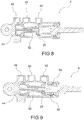
- reference numeral 4 globally denotes an actuator device for brakes suitable to be operatively connected to at least a first braking device 8 acting on a brake disc or drum 10, so as to exercise a braking action.
- the first braking device 8 may comprise a caliper for a disc brake arranged astride a brake disc or may comprise one or more shoes which intercept a drum of a drum brake.
- the braking device 8 may be operatively connected to further braking devices 11, comprising both calipers for disc brakes and drums, acting on the same or on separate wheels of a vehicle; said wheels may be on the same axle or on different axles of the vehicle.
- the actuator device for brakes 4 is fitted with a lever and/or pedal 12 for its manual operation, and is provided with a body 16 which houses at least one piston 20 which acts on a hydraulic circuit 24 fluidically connected to said at least one first braking device 8 for the hydraulic operation thereof.
- the lever and/or pedal 12 are operatively connected to said piston 20 so as to command its movement or operating stroke in an operating direction X, to exert pressure on the fluid of the hydraulic circuit.
- the actuator device for brakes 4 is fitted with an automatic actuator 28, operatively connected to the piston 20 and/or to the operating lever and/or pedal 12, so as to increase, control or reduce the braking action imposed manually by operating the operating lever and/or pedal 12, controlling the operating stroke of the piston 20.
- the automatic actuator 28 is at least partially housed in the body 16 of the actuator device for brakes 4.
- the automatic actuator 28 is mechanically associated to the body 16 of the actuator device for brakes 4.
- the body 16 identifies a first chamber 32 which houses said piston 20 fitted with at least a first head 36, the first chamber 32 being provided with a delivery opening 40 fluidically connected to the at least one first braking device 8 so as to receive the fluid pressurised by the first head 36 during the stroke of the piston.
- the body also defines an input opening 42 which serves to allow the flow of hydraulic fluid coming typically from a tank not shown (in the known manner). This input opening 42 flows into the first chamber 32 which houses the first head 36 of the piston 20.
- the first head 36 of the piston in the rest condition, does not occlude said input opening 42; therefore, the liquid coming from the tank is able to flow into the first chamber 32 so as to compensate for the wear of the pads of the braking devices.
- the first head 36 occludes the input opening 42 and pressurises the liquid contained in the first chamber 32.
- the first chamber 32 defines a delivery stage of the actuator device for brakes 4.
- the body 16 defines a second chamber 44 which houses a second head 48 of the piston 20, the second chamber 44 being in connection with the automatic actuator 28 so as to exert a thrust action on the piston 20 concordant or discordant with the thrust action exerted by the lever or operating pedal 12.
- the second chamber 44 identifies a control or contrast stage of the actuator device for brakes 4.
- the second chamber 44 is provided with a feed opening 46 of the contrast stage.
- the second chamber 44 houses a pusher element connected to the automatic actuator 28 and moved by relative drive means, said pusher element interfacing with the second head of the piston.
- the first and the second chambers 32, 44 are fluidically separate from each other.
- the second chamber 44 is filled with a liquid pressed by the automatic actuator 28, so as to be able to exercise a thrust action on the second head 48 following the operation of the automatic actuator device 28.
- the first and second chambers 32, 44 are positioned in series with each other and at least partially separated by a separation septum 52 fixed in relation to the body 16, the piston 20 comprising a stem 56 slidingly joined in an airtight manner to a hole 60 made on said separation septum 52, the stem 56 connecting the first and second heads 36, 48 of the piston 20 to each other.
- the second chamber 44 houses elastic return means 64 which exercise a thrust action on the piston 20 pressing it towards a rest condition, in a rest direction Y, opposite said operating direction X.
- the body 16 houses coaxial stages.
- the body 8 houses the first chamber 32, which defines a delivery stage, and the second chamber 44, which defines a contrast or control stage, wherein said chambers 32, 44 are coaxial and at least partially penetrate each other, despite being fluidically separate from each other.
- the body 16 also delimits a compensation stage defined by a compensation chamber 58 which acts as compensation for variations in the level of liquid of the hydraulic circuit connected to the actuator device for brakes 4.
- a compensation stage defined by a compensation chamber 58 which acts as compensation for variations in the level of liquid of the hydraulic circuit connected to the actuator device for brakes 4.
- the automatic actuator 28 comprises motor means 68 and a pump 72, operatively connected to said motor means 68, able to pressurise the fluid to send to the body 16 of the actuator device for brakes 4.
- the pressurised fluid may act on the second head 48 of the piston 20 so as to exert on the piston 20 a thrust in a rest direction Y which opposes the thrust in the operating direction X imposed by the lever or operating pedal 12.
- Said motor means 68 are mechanically connected to the pump or to a part thereof by means of a kinematism 76.
- said at least one kinematism 76 comprises ball bearing screws.
- the automatic actuator 28 comprises contrast means 80 operatively connected to the lever or pedal 12, so as to be able to exercise a thrust action in accordance or discordance with the operating thrust on the lever or pedal 12.
- contrast means 80 are directly connected to a portion of the operating lever or pedal 12.
- the contrast means 80 are connected to a transmission 84 which operatively connects the operating lever or pedal 12 to the piston 20.
- the contrast means 80 are operated by an electric, hydraulic or pneumatic motor.
- said electric, hydraulic or pneumatic motor is operatively connected to the contrast means 80 by means of at least one kinematism comprising ball bearing screws.
- the actuator device for brakes 4 comprises at least one command panel 88 operatively connected to the automatic actuator 28, so as to control the actuation thereof depending on the measurement parameters of the dynamic functioning of the associable vehicle 92.
- the actuator device for brakes according to the invention makes it possible to overcome the drawbacks of the prior art.
- the actuator device for brakes allows the user to always have the direct sensation of the manual actuation of the braking device and at the same time to always have the clear and precise sensation of any intervention by the control system of the vehicle to optimise the braking phase and/or to stabilise the vehicle dynamics.
- the user always has the direct control of at least a portion of the hydraulic system connected to the braking devices, and consequently always has the sensation and direct control of said system or of at least a portion thereof, even when the system does not intervene to correct the braking request or to dynamically stabilise the vehicle.
- the actuator device for brakes is also compact, functional and lightweight.
Landscapes
- Engineering & Computer Science (AREA)
- Transportation (AREA)
- Mechanical Engineering (AREA)
- Physics & Mathematics (AREA)
- Fluid Mechanics (AREA)
- Regulating Braking Force (AREA)
- Braking Elements And Transmission Devices (AREA)
- Braking Arrangements (AREA)
Claims (15)
- Dispositif d'actionnement de freins (4) adapté à être raccordé fonctionnellement à au moins un premier dispositif de freinage (8) agissant sur un disque ou un tambour de frein (10), de façon à pratiquer une action de freinage,- le dispositif d'actionnement de freins (4) étant muni d'un levier et/ou d'une pédale (12) pour son fonctionnement manuel, et étant pourvu d'un corps (16) qui loge au moins un piston (20) qui agit sur un circuit hydraulique (24) raccordé fluidiquement audit au moins un premier dispositif de freinage (8) pour son fonctionnement hydraulique,- le levier et/ou la pédale (12) étant raccordés fonctionnellement audit piston (20) de façon à commander son mouvement ou sa course de fonctionnement dans une direction de fonctionnement (X), de façon à exercer une pression sur le fluide du circuit hydraulique (24),dans lequel
le dispositif d'actionnement de freins (4) est muni d'un actionneur automatique (28), raccordé fonctionnellement au piston (20) et/ou au levier et/ou à la pédale de fonctionnement (12), de façon à augmenter, réguler, ou réduire l'action de freinage imposée manuellement par le fonctionnement du levier et/ou de la pédale de fonctionnement (12), la commande de la course de fonctionnement du piston (20), caractérisé en ce que
le corps (16) identifie une première chambre (32) qui loge ledit piston (20) muni d'au moins une première tête (36), la première chambre (32) étant pourvue d'une ouverture de distribution (40) raccordée fluidiquement à l'au moins un premier dispositif de freinage (8) de façon à recevoir le fluide pressurisé par la première tête (36) pendant la course du piston (20), dans lequel le corps (16) identifie une seconde chambre (44) qui loge une seconde tête (48) du piston (20), la seconde chambre (44) étant en raccordement avec l'actionneur automatique (28) de façon à pratiquer sur le piston (20) une action de poussée en accord ou en désaccord avec l'action de poussée pratiquée par le levier et/ou la pédale de fonctionnement (12). - Dispositif d'actionnement de freins (4) selon la revendication 1, dans lequel la seconde chambre (44) loge un élément pousseur raccordé à l'actionneur automatique (28) et déplacé par des moyens d'entraînement relatifs, ledit élément pousseur servant d'interface avec la seconde tête (48) du piston (20).
- Dispositif d'actionnement de freins (4) selon la revendication 1 ou 2, dans lequel la première et la seconde chambre (32, 44) sont séparées fluidiquement l'une de l'autre.
- Dispositif d'actionnement de freins (4) selon la revendication 1, 2 ou 3, dans lequel la seconde chambre (44) est remplie d'un liquide sur lequel appuie l'actionneur automatique (28), de façon à pouvoir pratiquer une action de poussée sur la seconde tête (48) suite au fonctionnement de l'actionneur automatique (28).
- Dispositif d'actionnement de freins (4) selon l'une quelconque des revendications 1 à 4, dans lequel lesdites première et seconde chambres (32, 44) sont positionnées en série l'une avec l'autre et au moins partiellement séparées (52) par une cloison de séparation (52) fixe par rapport au corps (16), le piston (20) comprenant une tige (56) jointe avec capacité de coulissement de manière étanche à un trou (60) réalisé sur ladite cloison de séparation (52), la tige (56) raccordant la première et la seconde tête (36, 48) du piston (20) l'une à l'autre.
- Dispositif d'actionnement de freins (4) selon l'une quelconque des revendications 1 à 5, dans lequel la seconde chambre (44) loge des moyens de rappel élastique (64) qui pratiquent une action de poussée sur le piston (20) l'appuyant vers une condition de repos, dans une direction de repos (Y), opposée à ladite direction de fonctionnement (X).
- Dispositif d'actionnement de freins (4) selon l'une quelconque des revendications précédentes, dans lequel le corps (16) loge une première chambre (32), qui définit un étage de distribution, une seconde chambre (44), qui définit un étage de contraste ou de régulation, dans lequel lesdites chambres (32, 44) sont coaxiales et pénètrent au moins partiellement l'une dans l'autre, en dépit du fait qu'elles sont séparées fluidiquement l'une de l'autre.
- Dispositif d'actionnement de freins (4) selon la revendication 7, dans lequel le corps (16) délimite également un étage de compensation défini par une chambre de compensation (58) qui sert de compensation pour des variations du niveau de liquide du circuit hydraulique (24) raccordé au dispositif d'actionnement de freins (4).
- Dispositif d'actionnement de freins (4) selon l'une quelconque des revendications précédentes, dans lequel l'actionneur automatique (28) comprend des moyens de moteur (68) et une pompe (72), raccordée fonctionnellement auxdits moyens de moteur (68), capables de pressuriser le fluide pour l'envoyer au corps (16) du dispositif d'actionnement de freins (4).
- Dispositif d'actionnement de freins (4) selon l'une quelconque des revendications précédentes, dans lequel l'actionneur automatique (28) comprend des moyens de contraste (80) raccordés fonctionnellement au levier et/ou à la pédale (12), de façon à être capables de pratiquer une action de poussée en accord ou en désaccord avec la poussée de fonctionnement sur le levier ou la pédale (12).
- Dispositif d'actionnement de freins (4) selon la revendication 10, dans lequel lesdits moyens de contraste (80) sont raccordés directement à une portion du levier ou de la pédale de fonctionnement (12).
- Dispositif d'actionnement de freins (4) selon la revendication 10, dans lequel lesdits moyens de contraste (80) sont raccordés à une transmission (84) qui raccorde fonctionnellement le levier ou la pédale de fonctionnement (12) au piston (20).
- Dispositif d'actionnement de freins (4) selon l'une quelconque des revendications précédentes, dans lequel l'actionneur automatique (28) est logé au moins partiellement dans le corps (16) du dispositif d'actionnement de freins (4).
- Dispositif d'actionnement de freins (4) selon l'une quelconque des revendications précédentes, dans lequel l'actionneur automatique (28) est associé mécaniquement au corps (16) du dispositif d'actionnement de freins (4).
- Dispositif d'actionnement de freins (4) selon l'une quelconque des revendications précédentes, comprenant au moins un panneau de régulation (88) raccordé fonctionnellement à l'actionneur automatique (28), de façon à réguler son actionnement en fonction des paramètres de mesure du fonctionnement dynamique du véhicule pouvant être associé (92).
Applications Claiming Priority (2)
| Application Number | Priority Date | Filing Date | Title |
|---|---|---|---|
| IT001050A ITTO20131050A1 (it) | 2013-12-19 | 2013-12-19 | Dispositivo attuatore per freni a controllo automatico |
| PCT/IB2014/067001 WO2015092699A2 (fr) | 2013-12-19 | 2014-12-17 | Dispositif d'actionnement de freins à commande automatique |
Publications (3)
| Publication Number | Publication Date |
|---|---|
| EP3083347A2 EP3083347A2 (fr) | 2016-10-26 |
| EP3083347B1 true EP3083347B1 (fr) | 2020-12-09 |
| EP3083347B8 EP3083347B8 (fr) | 2021-09-01 |
Family
ID=50159438
Family Applications (1)
| Application Number | Title | Priority Date | Filing Date |
|---|---|---|---|
| EP14830687.1A Active EP3083347B8 (fr) | 2013-12-19 | 2014-12-17 | Dispositif d'actionnement de freins à commande automatique |
Country Status (5)
| Country | Link |
|---|---|
| US (2) | US10023160B2 (fr) |
| EP (1) | EP3083347B8 (fr) |
| ES (1) | ES2857563T3 (fr) |
| IT (1) | ITTO20131050A1 (fr) |
| WO (1) | WO2015092699A2 (fr) |
Families Citing this family (2)
| Publication number | Priority date | Publication date | Assignee | Title |
|---|---|---|---|---|
| ES2964118T3 (es) * | 2018-09-19 | 2024-04-04 | Brembo Spa | Sistema de frenado de freno por cable eléctrico controlado de manera automática para motocicletas |
| TWI707795B (zh) * | 2019-07-10 | 2020-10-21 | 彥豪金屬工業股份有限公司 | 自行車卡鉗、自行車卡鉗控制系統及自行車卡鉗控制方法 |
Family Cites Families (18)
| Publication number | Priority date | Publication date | Assignee | Title |
|---|---|---|---|---|
| DE8608011U1 (de) * | 1986-03-22 | 1987-04-09 | Robert Bosch Gmbh, 7000 Stuttgart | Elektro-hydraulische Bremse |
| JP3613623B2 (ja) * | 1997-01-06 | 2005-01-26 | 愛知機械工業株式会社 | 油圧マスタシリンダの作動装置 |
| JP5014919B2 (ja) * | 2007-08-17 | 2012-08-29 | 日立オートモティブシステムズ株式会社 | ブレーキ制御装置 |
| DE102008014462A1 (de) * | 2008-03-14 | 2009-09-17 | Robert Bosch Gmbh | Hydraulische Fahrzeugbremsanlage |
| JP5096987B2 (ja) * | 2008-04-03 | 2012-12-12 | 日立オートモティブシステムズ株式会社 | ブレーキ倍力装置 |
| DE102008054852A1 (de) * | 2008-12-18 | 2010-07-01 | Robert Bosch Gmbh | Elektromechanischer Bremskraftverstärker |
| JP5273472B2 (ja) * | 2009-04-30 | 2013-08-28 | 日立オートモティブシステムズ株式会社 | ブレーキシステム |
| JP5135311B2 (ja) * | 2009-09-30 | 2013-02-06 | 日立オートモティブシステムズ株式会社 | 電動倍力装置 |
| DE202010017605U1 (de) * | 2010-02-15 | 2012-10-08 | Robert Bosch Gmbh | Bremskraftverstärker sowie Verfahren und Vorrichtung zu dessen Betrieb |
| JP5685791B2 (ja) * | 2010-09-29 | 2015-03-18 | 日立オートモティブシステムズ株式会社 | 倍力装置 |
| JP5721068B2 (ja) * | 2010-12-09 | 2015-05-20 | 日立オートモティブシステムズ株式会社 | 電動倍力装置 |
| US10005442B2 (en) * | 2011-09-29 | 2018-06-26 | Hitachi Automotive Systems, Ltd. | Brake control device |
| JP5850690B2 (ja) * | 2011-09-29 | 2016-02-03 | 日立オートモティブシステムズ株式会社 | ブレーキ制御装置 |
| FR3005294B1 (fr) * | 2013-05-03 | 2015-08-28 | Bosch Gmbh Robert | Servofrein electrohydraulique |
| DE102013217443B4 (de) * | 2013-09-02 | 2025-12-11 | Robert Bosch Gmbh | Elektromechanischer Bremskraftverstärker für ein Bremssystem eines Fahrzeugs und Verfahren zum Montieren eines elektromechanischen Bremskraftverstärkers an und/oder in einem Bremssystem für ein Fahrzeug |
| DE102014003641A1 (de) * | 2014-03-14 | 2015-09-17 | Lucas Automotive Gmbh | Kalibrierverfahren für eine elektrohydraulische Kraftfahrzeug-Bremsanlage und Kalibriervorrichtung hierfür |
| DE102015200106B3 (de) * | 2015-01-08 | 2016-05-12 | Ford Global Technologies, Llc | Steuerungsverfahren für ein hydraulisches Bremssystem eines Kraftfahrzeugs sowie hydraulisches Bremssystem |
| US10023166B2 (en) * | 2015-02-27 | 2018-07-17 | Hitachi Automotive Systems, Ltd. | Brake control device |
-
2013
- 2013-12-19 IT IT001050A patent/ITTO20131050A1/it unknown
-
2014
- 2014-12-17 WO PCT/IB2014/067001 patent/WO2015092699A2/fr not_active Ceased
- 2014-12-17 US US14/999,691 patent/US10023160B2/en active Active
- 2014-12-17 EP EP14830687.1A patent/EP3083347B8/fr active Active
- 2014-12-17 ES ES14830687T patent/ES2857563T3/es active Active
-
2018
- 2018-05-18 US US15/983,641 patent/US20180312145A1/en not_active Abandoned
Non-Patent Citations (1)
| Title |
|---|
| None * |
Also Published As
| Publication number | Publication date |
|---|---|
| ES2857563T3 (es) | 2021-09-29 |
| EP3083347B8 (fr) | 2021-09-01 |
| US20160362092A1 (en) | 2016-12-15 |
| ITTO20131050A1 (it) | 2015-06-20 |
| EP3083347A2 (fr) | 2016-10-26 |
| US10023160B2 (en) | 2018-07-17 |
| US20180312145A1 (en) | 2018-11-01 |
| WO2015092699A2 (fr) | 2015-06-25 |
| WO2015092699A3 (fr) | 2015-11-05 |
Similar Documents
| Publication | Publication Date | Title |
|---|---|---|
| CN102762420B (zh) | 制动助力器以及对其进行操作的方法和装置 | |
| JP7451503B2 (ja) | モータサイクル用の自動制御されたブレーキ・バイ・ワイヤ式ブレーキシステム | |
| US11332105B2 (en) | Braking system for vehicles, in particular for cycles and motorcycles, and actuation method for a braking system | |
| US20110251769A1 (en) | Operation of a brake booster as a pedal simulator | |
| KR102286836B1 (ko) | 차량용 제동 장치 | |
| EP3386812B1 (fr) | Brake-by-wire systeme de freinage pour véhucules avec simulation de rétroaction hydraulique, et un tel -procédé | |
| JP6756920B2 (ja) | 車両制動システム及び方法 | |
| US10632979B2 (en) | Automatically controlled braking system for vehicles and method of actuating and controlling a braking system for vehicles | |
| US20150291137A1 (en) | Braking device for vehicle designed to achieve smooth deceleration | |
| US20180312145A1 (en) | Automatically Controlled Actuator Device For Brakes | |
| EP3178712B1 (fr) | Système de freinage de type « freinage électronique » pour véhicules pourvu de simulateur hydraulique et procédé d'actionnement | |
| EP3009314B1 (fr) | Système de freins pour véhicule controlé automatiquement et procédé correspondant d'actuation d'un tel système | |
| EP3083349B1 (fr) | Système de freinage à commande automatique | |
| EP4267438B1 (fr) | Système de freinage intégré pour motocyclettes et motocyclette associée | |
| EP3445624B1 (fr) | Système de freinage commandé automatisé pour véhicules | |
| WO2017115245A1 (fr) | Système de freinage à commande automatique pour véhicules |
Legal Events
| Date | Code | Title | Description |
|---|---|---|---|
| PUAI | Public reference made under article 153(3) epc to a published international application that has entered the european phase |
Free format text: ORIGINAL CODE: 0009012 |
|
| 17P | Request for examination filed |
Effective date: 20160616 |
|
| AK | Designated contracting states |
Kind code of ref document: A2 Designated state(s): AL AT BE BG CH CY CZ DE DK EE ES FI FR GB GR HR HU IE IS IT LI LT LU LV MC MK MT NL NO PL PT RO RS SE SI SK SM TR |
|
| AX | Request for extension of the european patent |
Extension state: BA ME |
|
| DAX | Request for extension of the european patent (deleted) | ||
| GRAP | Despatch of communication of intention to grant a patent |
Free format text: ORIGINAL CODE: EPIDOSNIGR1 |
|
| STAA | Information on the status of an ep patent application or granted ep patent |
Free format text: STATUS: GRANT OF PATENT IS INTENDED |
|
| INTG | Intention to grant announced |
Effective date: 20200717 |
|
| GRAS | Grant fee paid |
Free format text: ORIGINAL CODE: EPIDOSNIGR3 |
|
| GRAA | (expected) grant |
Free format text: ORIGINAL CODE: 0009210 |
|
| STAA | Information on the status of an ep patent application or granted ep patent |
Free format text: STATUS: THE PATENT HAS BEEN GRANTED |
|
| AK | Designated contracting states |
Kind code of ref document: B1 Designated state(s): AL AT BE BG CH CY CZ DE DK EE ES FI FR GB GR HR HU IE IS IT LI LT LU LV MC MK MT NL NO PL PT RO RS SE SI SK SM TR |
|
| REG | Reference to a national code |
Ref country code: GB Ref legal event code: FG4D |
|
| REG | Reference to a national code |
Ref country code: AT Ref legal event code: REF Ref document number: 1343115 Country of ref document: AT Kind code of ref document: T Effective date: 20201215 Ref country code: CH Ref legal event code: EP |
|
| REG | Reference to a national code |
Ref country code: DE Ref legal event code: R096 Ref document number: 602014073244 Country of ref document: DE |
|
| REG | Reference to a national code |
Ref country code: IE Ref legal event code: FG4D |
|
| PG25 | Lapsed in a contracting state [announced via postgrant information from national office to epo] |
Ref country code: GR Free format text: LAPSE BECAUSE OF FAILURE TO SUBMIT A TRANSLATION OF THE DESCRIPTION OR TO PAY THE FEE WITHIN THE PRESCRIBED TIME-LIMIT Effective date: 20210310 Ref country code: NO Free format text: LAPSE BECAUSE OF FAILURE TO SUBMIT A TRANSLATION OF THE DESCRIPTION OR TO PAY THE FEE WITHIN THE PRESCRIBED TIME-LIMIT Effective date: 20210309 Ref country code: FI Free format text: LAPSE BECAUSE OF FAILURE TO SUBMIT A TRANSLATION OF THE DESCRIPTION OR TO PAY THE FEE WITHIN THE PRESCRIBED TIME-LIMIT Effective date: 20201209 Ref country code: RS Free format text: LAPSE BECAUSE OF FAILURE TO SUBMIT A TRANSLATION OF THE DESCRIPTION OR TO PAY THE FEE WITHIN THE PRESCRIBED TIME-LIMIT Effective date: 20201209 |
|
| REG | Reference to a national code |
Ref country code: AT Ref legal event code: MK05 Ref document number: 1343115 Country of ref document: AT Kind code of ref document: T Effective date: 20201209 |
|
| PG25 | Lapsed in a contracting state [announced via postgrant information from national office to epo] |
Ref country code: SE Free format text: LAPSE BECAUSE OF FAILURE TO SUBMIT A TRANSLATION OF THE DESCRIPTION OR TO PAY THE FEE WITHIN THE PRESCRIBED TIME-LIMIT Effective date: 20201209 Ref country code: LV Free format text: LAPSE BECAUSE OF FAILURE TO SUBMIT A TRANSLATION OF THE DESCRIPTION OR TO PAY THE FEE WITHIN THE PRESCRIBED TIME-LIMIT Effective date: 20201209 Ref country code: BG Free format text: LAPSE BECAUSE OF FAILURE TO SUBMIT A TRANSLATION OF THE DESCRIPTION OR TO PAY THE FEE WITHIN THE PRESCRIBED TIME-LIMIT Effective date: 20210309 |
|
| REG | Reference to a national code |
Ref country code: NL Ref legal event code: MP Effective date: 20201209 |
|
| PG25 | Lapsed in a contracting state [announced via postgrant information from national office to epo] |
Ref country code: NL Free format text: LAPSE BECAUSE OF FAILURE TO SUBMIT A TRANSLATION OF THE DESCRIPTION OR TO PAY THE FEE WITHIN THE PRESCRIBED TIME-LIMIT Effective date: 20201209 Ref country code: HR Free format text: LAPSE BECAUSE OF FAILURE TO SUBMIT A TRANSLATION OF THE DESCRIPTION OR TO PAY THE FEE WITHIN THE PRESCRIBED TIME-LIMIT Effective date: 20201209 |
|
| REG | Reference to a national code |
Ref country code: LT Ref legal event code: MG9D |
|
| RAP4 | Party data changed (patent owner data changed or rights of a patent transferred) |
Owner name: BREMBO S.P.A. |
|
| RIN2 | Information on inventor provided after grant (corrected) |
Inventor name: COMENDULI, ALBERTO Inventor name: GUALANDRIS, MASSIMO Inventor name: ARIENTI, ROBERTO Inventor name: CANTONI, CARLO |
|
| PG25 | Lapsed in a contracting state [announced via postgrant information from national office to epo] |
Ref country code: SK Free format text: LAPSE BECAUSE OF FAILURE TO SUBMIT A TRANSLATION OF THE DESCRIPTION OR TO PAY THE FEE WITHIN THE PRESCRIBED TIME-LIMIT Effective date: 20201209 Ref country code: PT Free format text: LAPSE BECAUSE OF FAILURE TO SUBMIT A TRANSLATION OF THE DESCRIPTION OR TO PAY THE FEE WITHIN THE PRESCRIBED TIME-LIMIT Effective date: 20210409 Ref country code: RO Free format text: LAPSE BECAUSE OF FAILURE TO SUBMIT A TRANSLATION OF THE DESCRIPTION OR TO PAY THE FEE WITHIN THE PRESCRIBED TIME-LIMIT Effective date: 20201209 Ref country code: LT Free format text: LAPSE BECAUSE OF FAILURE TO SUBMIT A TRANSLATION OF THE DESCRIPTION OR TO PAY THE FEE WITHIN THE PRESCRIBED TIME-LIMIT Effective date: 20201209 Ref country code: SM Free format text: LAPSE BECAUSE OF FAILURE TO SUBMIT A TRANSLATION OF THE DESCRIPTION OR TO PAY THE FEE WITHIN THE PRESCRIBED TIME-LIMIT Effective date: 20201209 Ref country code: CZ Free format text: LAPSE BECAUSE OF FAILURE TO SUBMIT A TRANSLATION OF THE DESCRIPTION OR TO PAY THE FEE WITHIN THE PRESCRIBED TIME-LIMIT Effective date: 20201209 Ref country code: EE Free format text: LAPSE BECAUSE OF FAILURE TO SUBMIT A TRANSLATION OF THE DESCRIPTION OR TO PAY THE FEE WITHIN THE PRESCRIBED TIME-LIMIT Effective date: 20201209 |
|
| REG | Reference to a national code |
Ref country code: CH Ref legal event code: PL Ref country code: CH Ref legal event code: PK Free format text: BERICHTIGUNGEN |
|
| REG | Reference to a national code |
Ref country code: CH Ref legal event code: PK Free format text: BERICHTIGUNG B8 |
|
| RAP4 | Party data changed (patent owner data changed or rights of a patent transferred) |
Owner name: BREMBO S.P.A. |
|
| RIN2 | Information on inventor provided after grant (corrected) |
Inventor name: COMENDULI, ALBERTO Inventor name: GUALANDRIS, MASSIMO Inventor name: ARIENTI, ROBERTO Inventor name: CANTONI, CARLO |
|
| PG25 | Lapsed in a contracting state [announced via postgrant information from national office to epo] |
Ref country code: PL Free format text: LAPSE BECAUSE OF FAILURE TO SUBMIT A TRANSLATION OF THE DESCRIPTION OR TO PAY THE FEE WITHIN THE PRESCRIBED TIME-LIMIT Effective date: 20201209 Ref country code: AT Free format text: LAPSE BECAUSE OF FAILURE TO SUBMIT A TRANSLATION OF THE DESCRIPTION OR TO PAY THE FEE WITHIN THE PRESCRIBED TIME-LIMIT Effective date: 20201209 |
|
| REG | Reference to a national code |
Ref country code: BE Ref legal event code: MM Effective date: 20201231 |
|
| REG | Reference to a national code |
Ref country code: DE Ref legal event code: R097 Ref document number: 602014073244 Country of ref document: DE |
|
| REG | Reference to a national code |
Ref country code: ES Ref legal event code: FG2A Ref document number: 2857563 Country of ref document: ES Kind code of ref document: T3 Effective date: 20210929 |
|
| PG25 | Lapsed in a contracting state [announced via postgrant information from national office to epo] |
Ref country code: IS Free format text: LAPSE BECAUSE OF FAILURE TO SUBMIT A TRANSLATION OF THE DESCRIPTION OR TO PAY THE FEE WITHIN THE PRESCRIBED TIME-LIMIT Effective date: 20210409 Ref country code: MC Free format text: LAPSE BECAUSE OF FAILURE TO SUBMIT A TRANSLATION OF THE DESCRIPTION OR TO PAY THE FEE WITHIN THE PRESCRIBED TIME-LIMIT Effective date: 20201209 |
|
| PLBE | No opposition filed within time limit |
Free format text: ORIGINAL CODE: 0009261 |
|
| STAA | Information on the status of an ep patent application or granted ep patent |
Free format text: STATUS: NO OPPOSITION FILED WITHIN TIME LIMIT |
|
| PG25 | Lapsed in a contracting state [announced via postgrant information from national office to epo] |
Ref country code: IT Free format text: LAPSE BECAUSE OF FAILURE TO SUBMIT A TRANSLATION OF THE DESCRIPTION OR TO PAY THE FEE WITHIN THE PRESCRIBED TIME-LIMIT Effective date: 20201209 Ref country code: IE Free format text: LAPSE BECAUSE OF NON-PAYMENT OF DUE FEES Effective date: 20201217 Ref country code: AL Free format text: LAPSE BECAUSE OF FAILURE TO SUBMIT A TRANSLATION OF THE DESCRIPTION OR TO PAY THE FEE WITHIN THE PRESCRIBED TIME-LIMIT Effective date: 20201209 Ref country code: LU Free format text: LAPSE BECAUSE OF NON-PAYMENT OF DUE FEES Effective date: 20201217 |
|
| 26N | No opposition filed |
Effective date: 20210910 |
|
| PG25 | Lapsed in a contracting state [announced via postgrant information from national office to epo] |
Ref country code: LI Free format text: LAPSE BECAUSE OF NON-PAYMENT OF DUE FEES Effective date: 20201231 Ref country code: SI Free format text: LAPSE BECAUSE OF FAILURE TO SUBMIT A TRANSLATION OF THE DESCRIPTION OR TO PAY THE FEE WITHIN THE PRESCRIBED TIME-LIMIT Effective date: 20201209 Ref country code: CH Free format text: LAPSE BECAUSE OF NON-PAYMENT OF DUE FEES Effective date: 20201231 Ref country code: DK Free format text: LAPSE BECAUSE OF FAILURE TO SUBMIT A TRANSLATION OF THE DESCRIPTION OR TO PAY THE FEE WITHIN THE PRESCRIBED TIME-LIMIT Effective date: 20201209 |
|
| PG25 | Lapsed in a contracting state [announced via postgrant information from national office to epo] |
Ref country code: IS Free format text: LAPSE BECAUSE OF FAILURE TO SUBMIT A TRANSLATION OF THE DESCRIPTION OR TO PAY THE FEE WITHIN THE PRESCRIBED TIME-LIMIT Effective date: 20210409 Ref country code: TR Free format text: LAPSE BECAUSE OF FAILURE TO SUBMIT A TRANSLATION OF THE DESCRIPTION OR TO PAY THE FEE WITHIN THE PRESCRIBED TIME-LIMIT Effective date: 20201209 Ref country code: MT Free format text: LAPSE BECAUSE OF FAILURE TO SUBMIT A TRANSLATION OF THE DESCRIPTION OR TO PAY THE FEE WITHIN THE PRESCRIBED TIME-LIMIT Effective date: 20201209 Ref country code: CY Free format text: LAPSE BECAUSE OF FAILURE TO SUBMIT A TRANSLATION OF THE DESCRIPTION OR TO PAY THE FEE WITHIN THE PRESCRIBED TIME-LIMIT Effective date: 20201209 |
|
| PG25 | Lapsed in a contracting state [announced via postgrant information from national office to epo] |
Ref country code: MK Free format text: LAPSE BECAUSE OF FAILURE TO SUBMIT A TRANSLATION OF THE DESCRIPTION OR TO PAY THE FEE WITHIN THE PRESCRIBED TIME-LIMIT Effective date: 20201209 |
|
| PG25 | Lapsed in a contracting state [announced via postgrant information from national office to epo] |
Ref country code: BE Free format text: LAPSE BECAUSE OF NON-PAYMENT OF DUE FEES Effective date: 20201231 |
|
| REG | Reference to a national code |
Ref country code: DE Ref legal event code: R081 Ref document number: 602014073244 Country of ref document: DE Owner name: BREMBO S.P.A., CURNO, IT Free format text: FORMER OWNER: FRENI BREMBO S.P.A., CURNO, BERGAMO, IT |
|
| P01 | Opt-out of the competence of the unified patent court (upc) registered |
Effective date: 20230526 |
|
| PGFP | Annual fee paid to national office [announced via postgrant information from national office to epo] |
Ref country code: GB Payment date: 20251219 Year of fee payment: 12 |
|
| PGFP | Annual fee paid to national office [announced via postgrant information from national office to epo] |
Ref country code: FR Payment date: 20251128 Year of fee payment: 12 |
|
| PGFP | Annual fee paid to national office [announced via postgrant information from national office to epo] |
Ref country code: ES Payment date: 20260102 Year of fee payment: 12 |
|
| PGFP | Annual fee paid to national office [announced via postgrant information from national office to epo] |
Ref country code: DE Payment date: 20251222 Year of fee payment: 12 |