EP3083313B1 - Kraftstoff-sammeleinrichtung eines kraftfahrzeuges - Google Patents
Kraftstoff-sammeleinrichtung eines kraftfahrzeuges Download PDFInfo
- Publication number
- EP3083313B1 EP3083313B1 EP14821097.4A EP14821097A EP3083313B1 EP 3083313 B1 EP3083313 B1 EP 3083313B1 EP 14821097 A EP14821097 A EP 14821097A EP 3083313 B1 EP3083313 B1 EP 3083313B1
- Authority
- EP
- European Patent Office
- Prior art keywords
- fuel
- part structures
- collection device
- prefilter
- structures
- Prior art date
- Legal status (The legal status is an assumption and is not a legal conclusion. Google has not performed a legal analysis and makes no representation as to the accuracy of the status listed.)
- Active
Links
Images

Classifications
-
- B—PERFORMING OPERATIONS; TRANSPORTING
- B60—VEHICLES IN GENERAL
- B60K—ARRANGEMENT OR MOUNTING OF PROPULSION UNITS OR OF TRANSMISSIONS IN VEHICLES; ARRANGEMENT OR MOUNTING OF PLURAL DIVERSE PRIME-MOVERS IN VEHICLES; AUXILIARY DRIVES FOR VEHICLES; INSTRUMENTATION OR DASHBOARDS FOR VEHICLES; ARRANGEMENTS IN CONNECTION WITH COOLING, AIR INTAKE, GAS EXHAUST OR FUEL SUPPLY OF PROPULSION UNITS IN VEHICLES
- B60K15/00—Arrangement in connection with fuel supply of combustion engines or other fuel consuming energy converters, e.g. fuel cells; Mounting or construction of fuel tanks
- B60K15/03—Fuel tanks
- B60K15/077—Fuel tanks with means modifying or controlling distribution or motion of fuel, e.g. to prevent noise, surge, splash or fuel starvation
-
- B—PERFORMING OPERATIONS; TRANSPORTING
- B60—VEHICLES IN GENERAL
- B60K—ARRANGEMENT OR MOUNTING OF PROPULSION UNITS OR OF TRANSMISSIONS IN VEHICLES; ARRANGEMENT OR MOUNTING OF PLURAL DIVERSE PRIME-MOVERS IN VEHICLES; AUXILIARY DRIVES FOR VEHICLES; INSTRUMENTATION OR DASHBOARDS FOR VEHICLES; ARRANGEMENTS IN CONNECTION WITH COOLING, AIR INTAKE, GAS EXHAUST OR FUEL SUPPLY OF PROPULSION UNITS IN VEHICLES
- B60K15/00—Arrangement in connection with fuel supply of combustion engines or other fuel consuming energy converters, e.g. fuel cells; Mounting or construction of fuel tanks
- B60K15/03—Fuel tanks
- B60K2015/03111—Swirl pots
-
- B—PERFORMING OPERATIONS; TRANSPORTING
- B60—VEHICLES IN GENERAL
- B60K—ARRANGEMENT OR MOUNTING OF PROPULSION UNITS OR OF TRANSMISSIONS IN VEHICLES; ARRANGEMENT OR MOUNTING OF PLURAL DIVERSE PRIME-MOVERS IN VEHICLES; AUXILIARY DRIVES FOR VEHICLES; INSTRUMENTATION OR DASHBOARDS FOR VEHICLES; ARRANGEMENTS IN CONNECTION WITH COOLING, AIR INTAKE, GAS EXHAUST OR FUEL SUPPLY OF PROPULSION UNITS IN VEHICLES
- B60K15/00—Arrangement in connection with fuel supply of combustion engines or other fuel consuming energy converters, e.g. fuel cells; Mounting or construction of fuel tanks
- B60K15/03—Fuel tanks
- B60K2015/03236—Fuel tanks characterised by special filters, the mounting thereof
-
- B—PERFORMING OPERATIONS; TRANSPORTING
- B60—VEHICLES IN GENERAL
- B60K—ARRANGEMENT OR MOUNTING OF PROPULSION UNITS OR OF TRANSMISSIONS IN VEHICLES; ARRANGEMENT OR MOUNTING OF PLURAL DIVERSE PRIME-MOVERS IN VEHICLES; AUXILIARY DRIVES FOR VEHICLES; INSTRUMENTATION OR DASHBOARDS FOR VEHICLES; ARRANGEMENTS IN CONNECTION WITH COOLING, AIR INTAKE, GAS EXHAUST OR FUEL SUPPLY OF PROPULSION UNITS IN VEHICLES
- B60K15/00—Arrangement in connection with fuel supply of combustion engines or other fuel consuming energy converters, e.g. fuel cells; Mounting or construction of fuel tanks
- B60K15/03—Fuel tanks
- B60K2015/03256—Fuel tanks characterised by special valves, the mounting thereof
-
- B—PERFORMING OPERATIONS; TRANSPORTING
- B60—VEHICLES IN GENERAL
- B60K—ARRANGEMENT OR MOUNTING OF PROPULSION UNITS OR OF TRANSMISSIONS IN VEHICLES; ARRANGEMENT OR MOUNTING OF PLURAL DIVERSE PRIME-MOVERS IN VEHICLES; AUXILIARY DRIVES FOR VEHICLES; INSTRUMENTATION OR DASHBOARDS FOR VEHICLES; ARRANGEMENTS IN CONNECTION WITH COOLING, AIR INTAKE, GAS EXHAUST OR FUEL SUPPLY OF PROPULSION UNITS IN VEHICLES
- B60K15/00—Arrangement in connection with fuel supply of combustion engines or other fuel consuming energy converters, e.g. fuel cells; Mounting or construction of fuel tanks
- B60K15/03—Fuel tanks
- B60K15/077—Fuel tanks with means modifying or controlling distribution or motion of fuel, e.g. to prevent noise, surge, splash or fuel starvation
- B60K2015/0777—Fuel tanks with means modifying or controlling distribution or motion of fuel, e.g. to prevent noise, surge, splash or fuel starvation in-tank reservoirs or baffles integrally manufactured with the fuel Tank
Definitions
- the invention relates to a fuel collecting device of a motor vehicle with a swirl pot, with a arranged in the bottom region of the swirl pot pre-filter and made of plastic structures of the pre-filter.
- Such fuel collecting devices are mounted in today's motor vehicles via a retaining element on the bottom of a fuel tank and are known in practice. These collectors roughly clean the fuel through the pre-filter before entering the swirl pot.
- the aim is to protect the downstream functional elements, such as a bottom valve or a suction jet pump, from failure.
- the fuel is collected and conveyed by a fuel delivery device to an internal combustion engine of the motor vehicle. Due to the function, it is necessary that the pre-filter is arranged as close as possible to the bottom of the fuel tank. By using a holding element under the swirl pot this is raised and changed the promotion of the fuel in the swirl pot adversely.
- the pre-filter can be produced by structures made of plastic directly on the swirl pot. Compensation by extending the prefilter structures in the surge pot in a recess of the holding element deteriorates the filter performance with respect to the size of the dirt particles.
- Fuel collecting devices with the features of the preamble of claim 1 are known from DE 198 34 653 C1 and the EP 1 619 065 A1 known.
- the invention is based on the problem of further developing a fuel collecting device of the type mentioned at the beginning in such a way that it permits a particularly high filtering performance of the prefilter and is as simple to manufacture as possible.
- This problem is inventively solved in that the pre-filter on subjacent components each arranged sub-structures and that the substructures of the components face each other.
- the structures required for filtering are divided into two different components.
- the substructures of the individual components thus together form the structures of the prefilter.
- the partial structures can each be produced with a shallow depth, since together they form the intended depth.
- the substructures thereby have a particularly high mechanical stability. This allows a high filter performance of the pre-filter.
- the fuel collecting device is particularly easy to manufacture, since particularly fine structures of the prefilter are avoided.
- the number of components to be mounted can be kept particularly low if the one substructures on the swirl pot and the other substructures are arranged on a retaining element provided for fastening the swirl pot to a bottom of a fuel tank.
- no component to be mounted independently for the pre-filter is required because all components of the pre-filter are generated by the holding member and the swirl pot.
- holding element and swirl pot are aligned exactly to each other anyway, so that the proposed arrangement of the substructures to each other requires no additional effort.
- the substructures are preferably made in one piece with the plastic of the swirl pot and the holding element.
- the production of the prefilter is particularly simple according to another advantageous development of the invention, when the substructures are formed as elevations or depressions produced by injection molding.
- the substructures could, for example, interlock and thereby produce particularly small channels. However, this requires close tolerances of the substructures. Narrow tolerances of the substructures can be easily avoided according to another advantageous development of the invention, when the substructures lie on top of each other. In the simplest case, the partial structures are based on each other with their free ends.
- the partial structures could, for example, have pins, webs or the like.
- An effective pre-filtering can be achieved easily according to another advantageous embodiment of the invention, when the partial structures are designed arcuate.
- a labyrinth of channels in the pre-filter can be easily produced according to another advantageous development of the invention, when the arc shape of the two opposing substructures is arranged opposite to each other.
- the fuel collecting device is particularly compact if the substructures in the bottom area of the swirl pot are annular and if a bottom valve is arranged in the radially inner area of the substructures.
- Throttling points when flowing the fuel to the pre-filter can be largely avoided according to another advantageous embodiment of the invention, when the holding element is designed flat in the prefilter and when the swirl pot has a recess for inflow of the fuel to the pre-filter.
- the holding element can be designed as thin as possible, as required for the mechanical strength.
- the recess in the swirl pot allows the guidance of the fuel flowing from the fuel tank to the pre-filter.
- the substructures of the holding element allow according to another advantageous embodiment of the invention, a high filter performance when the recesses formed in the holding element partial structures taper towards the radially inner region of the prefilter and are longer than the partial structures of the surge pot.
- this can be designed particularly thin-walled, the holding element.
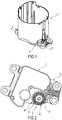
- FIG. 1 shows a fuel accumulator for a motor vehicle with a swirl pot 1 for collecting fuel and with a holding element 2.
- the holding member 2 serves to be attached to a bottom, not shown, of a fuel tank. Fuel is sucked out of the swirl pot 1 and conveyed to an internal combustion engine, likewise not shown, of the motor vehicle.
- FIG. 2 shows a sectional view through the fuel collecting device FIG. 1 along the line II - II. It can be seen that between the support member 2 and the swirl pot 1 a pre-filter 3 is arranged.
- the prefilter 3 has a multiplicity of structures 4 made of plastic, through which fuel flows radially outward into a radially inner region 5 and is filtered thereby.
- the structures 4 of the prefilter 3 are formed as superimposed annular part structures 6, 7.
- the annular partial structures 6, 7 each have an arcuate shape, wherein the two superimposed arched forms are aligned opposite to each other.
- FIG. 3 shows a plan view of the holding member 2 of the fuel collector FIG. 1 , It can be seen here that the holding element 2 is configured flat in the region of the prefilter 3.
- the holding element 2 has only one of the annular partial structures 6 FIG. 2 on.
- the arranged in the holding element 2 substructures 6 are formed as channel-like recesses 8 in the holding element 2. These channel-like recesses 8 taper towards the radially inner region 5 of the prefilter 3.
- FIG. 4 shows the swirl pot 1 from FIG. 1 in a view from below and thus a view of the holding element 2 from. It can be seen that the swirl pot 1 also only one of the annular partial structures 7 of the pre-filter 3 from FIG. 2 having.
- the annular partial structures 7 on the swirl pot 1 are formed by elevations 9 made of plastic by injection molding.
- openings 10 of a bottom valve 11 are arranged. About these openings 10 of the bottom valve 11 passes from the pre-filter 3 FIG. 2 Filtered fuel in the swirl pot 1.
- the swirl pot 1 has a part surrounding the structures 7 recess 12 for guiding the fuel to the pre-filter. 3
Landscapes
- Engineering & Computer Science (AREA)
- Life Sciences & Earth Sciences (AREA)
- Sustainable Development (AREA)
- Sustainable Energy (AREA)
- Chemical & Material Sciences (AREA)
- Combustion & Propulsion (AREA)
- Transportation (AREA)
- Mechanical Engineering (AREA)
- Cooling, Air Intake And Gas Exhaust, And Fuel Tank Arrangements In Propulsion Units (AREA)
- Filtration Of Liquid (AREA)
Description
- Die Erfindung betrifft eine Kraftstoff-Sammeleinrichtung eines Kraftfahrzeuges mit einem Schwalltopf, mit einem im Bodenbereich des Schwalltopfes angeordneten Vorfilter und mit aus Kunststoff gefertigten Strukturen des Vorfilters.
- Solche Kraftstoff-Sammeleinrichtungen werden in heutigen Kraftfahrzeugen über ein Halteelement am Boden eines Kraftstoffbehälters befestigt und sind aus der Praxis bekannt. Bei diesen Sammeleinrichtungen wird der Kraftstoff durch den Vorfilter grob gereinigt, bevor er in den Schwalltopf gelangt. Ziel ist es die nachgeschalteten Funktionselemente, wie beispielsweise ein Bodenventil oder eine Saugstrahlpumpe, vor einem Ausfall zu schützen. In dem Schwalltopf wird der Kraftstoff gesammelt und von einer Kraftstoff-Fördereinrichtung zu einer Brennkraftmaschine des Kraftfahrzeuges gefördert. Funktionsbedingt ist es notwendig, dass der Vorfilter so nahe wie möglich am Boden des Kraftstoffbehälters angeordnet ist. Durch die Verwendung eines Halteelementes unter dem Schwalltopf wird dieser angehoben und die Förderung des Kraftstoffs in dem Schwalltopf nachteilig verändert.
- Der Vorfilter lässt sich von aus Kunststoff gefertigten Strukturen unmittelbar am Schwalltopf erzeugen. Eine Kompensation durch Verlängerung der Vorfilterstrukturen im Schwalltopf in eine Vertiefung des Halteelementes verschlechtert die Filterleistung in Bezug auf die Größe der Schmutzteilchen.
- Kraftstoff-Sammeleinrichtungen mit den Merkmalen des Oberbegriffs des Anspruchs 1 sind aus der
DE 198 34 653 C1 und derEP 1 619 065 A1 bekannt. - Der Erfindung liegt das Problem zugrunde, eine Kraftstoff-Sammeleinrichtung der eingangs genannten Art so weiter zu bilden, dass sie eine besonders hohe Filterleistung des Vorfilters ermöglicht und möglichst einfach zu fertigen ist. Dieses Problem wird erfindungsgemäß dadurch gelöst, dass der Vorfilter auf einander gegenüberstehenden Bauteilen jeweils angeordnete Teilstrukturen aufweist und dass die Teilstrukturen der Bauteile einander gegenüberstehen.
- Durch diese Gestaltung sind die für die Filterung erforderlichen Strukturen auf zwei unterschiedliche Bauteile aufgeteilt. Die Teilstrukturen der einzelnen Bauteile bilden damit zusammen die Strukturen des Vorfilters. Die Teilstrukturen können dank der Erfindung jeweils mit geringer Tiefe erzeugt werden, da sie zusammen die vorgesehene Tiefe bilden. Die Teilstrukturen haben hierdurch eine besonders hohe mechanische Stabilität. Dies ermöglicht eine hohe Filterleistung des Vorfilters. Die Kraftstoff-Sammeleinrichtung ist jedoch dank der Erfindung besonders einfach zu fertigen, da besonders feine Strukturen des Vorfilters vermieden werden.
- Die Anzahl an zu montierenden Bauteilen lässt sich gemäß einer anderen vorteilhaften Weiterbildung der Erfindung besonders gering halten, wenn die einen Teilstrukturen auf dem Schwalltopf und die anderen Teilstrukturen auf einem zur Befestigung des Schwalltopfes an einem Boden eines Kraftstoffbehälters vorgesehenen Halteelement angeordnet sind. Durch diese Gestaltung ist kein eigenständig zu montierendes Bauteil für den Vorfilter erforderlich, da sämtliche Bauteile des Vorfilters von dem Halteelement und dem Schwalltopf erzeugt werden. Ein weiterer Vorteil dieser Gestaltung besteht darin, dass Halteelement und Schwalltopf ohnehin genau zueinander ausgerichtet sind, so dass die vorgesehene Anordnung der Teilstrukturen zueinander keinen zusätzlichen Aufwand erfordert. Die Teilstrukturen sind vorzugsweise einstückig mit dem Kunststoff des Schwalltopfes und des Halteelementes gefertigt.
- Die Fertigung des Vorfilters gestaltet sich gemäß einer anderen vorteilhaften Weiterbildung der Erfindung besonders einfach, wenn die Teilstrukturen als im Spritzgussverfahren erzeugte Erhebungen oder Vertiefungen ausgebildet sind.
- Die Teilstrukturen könnten beispielsweise ineinander greifen und hierdurch besonders kleine Kanäle erzeugen. Dies erfordert jedoch enge Toleranzen der Teilstrukturen. Enge Toleranzen der Teilstrukturen lassen sich gemäß einer anderen vorteilhaften Weiterbildung der Erfindung einfach vermeiden, wenn die Teilstrukturen aufeinander liegen. Im einfachsten Fall stützen sich die Teilstrukturen mit ihren freien Enden aneinander ab.
- Die Teilstrukturen könnten beispielsweise Zapfen, Stege oder dergleichen aufweisen. Eine wirksame Vorfilterung lässt sich gemäß einer anderen vorteilhaften Weiterbildung der Erfindung einfach erreichen, wenn die Teilstrukturen bogenförmig gestaltet sind.
- Ein Labyrinth an Kanälen im Vorfilter lässt sich gemäß einer anderen vorteilhaften Weiterbildung der Erfindung einfach erzeugen, wenn die Bogenform der beiden einander gegenüberstehenden Teilstrukturen zueinander entgegengesetzt angeordnet ist .
- Die Kraftstoff-Sammeleinrichtung gestaltet sich gemäß einer anderen vorteilhaften Weiterbildung der Erfindung besonders kompakt, wenn die Teilstrukturen im Bodenbereich des Schwalltopfes ringförmig gestaltet sind und wenn im radial inneren Bereich der Teilstrukturen ein Bodenventil angeordnet ist.
- Drosselstellen beim Einströmen des Kraftstoffs zu dem Vorfilter lassen sich gemäß einer anderen vorteilhaften Weiterbildung der Erfindung weitgehend vermeiden, wenn das Halteelement im Bereich des Vorfilters eben gestaltet ist und wenn der Schwalltopf eine Ausnehmung zum Einströmen des Kraftstoffs zu dem Vorfilter hat. Durch diese Gestaltung kann das Halteelement möglichst dünnwandig gestaltet sein, wie für die mechanische Festigkeit erforderlich ist. Die Ausnehmung im Schwalltopf ermöglicht die Führung des aus dem Kraftstoffbehälter anströmenden Kraftstoffs zu dem Vorfilter.
- Die Teilstrukturen des Halteelementes ermöglichen gemäß einer anderen vorteilhaften Weiterbildung der Erfindung eine hohe Filterleistung, wenn die als Vertiefungen in dem Halteelement ausgebildeten Teilstrukturen sich zu dem radial inneren Bereich des Vorfilters hin verjüngen und länger sind als die Teilstrukturen des Schwalltopfes. Zudem kann hierdurch das Halteelement besonders dünnwandig gestaltet sein.
- Die Erfindung lässt zahlreiche Ausführungsformen zu. Zur weiteren Verdeutlichung ihres Grundprinzips ist eine davon in der Zeichnung dargestellt und wird nachfolgend beschrieben. Diese zeigt in
- Fig. 1
- eine perspektivische Darstellung einer Kraftstoff-Sammeleinrichtung,
- Fig. 2
- eine Schnittdarstellung durch die Kraftstoff-Sammeleinrichtung aus
Figur 1 entlang der Linie II - II, - Fig. 3
- eine Draufsicht auf ein Halteelement der Kraftstoff-Sammeleinrichtung aus
Figur 1 , - Fig. 4
- eine Ansicht von unten auf einen Schwalltopf der Kraftstoff-Sammeleinrichtung aus
Figur 1 . -
Figur 1 zeigt eine Kraftstoff-Sammeleinrichtung für ein Kraftfahrzeug mit einem Schwalltopf 1 zum Sammeln von Kraftstoff und mit einem Halteelement 2. Das Halteelement 2 dient dazu, an einem nicht dargestellten Boden eines Kraftstoffbehälters befestigt zu werden. Aus dem Schwalltopf 1 wird Kraftstoff abgesaugt und zu einer ebenfalls nicht dargestellten Brennkraftmaschine des Kraftfahrzeuges gefördert. -
Figur 2 zeigt eine Schnittdarstellung durch die Kraftstoff-Sammeleinrichtung ausFigur 1 entlang der Linie II - II. Hierbei ist zu erkennen, dass zwischen dem Halteelement 2 und dem Schwalltopf 1 ein Vorfilter 3 angeordnet ist. Der Vorfilter 3 weist eine Vielzahl von aus Kunststoff gefertigten Strukturen 4 auf, durch die Kraftstoff von radial außen in einen radial inneren Bereich 5 strömt und dabei gefiltert wird. Die Strukturen 4 des Vorfilters 3 sind als übereinander liegende kranzförmige Teilstrukturen 6, 7 ausgebildet. Die kranzförmigen Teilstrukturen 6, 7 weisen jeweils Bogenform auf, wobei die zwei übereinander liegende Bogenformen zueinander entgegengesetzt ausgerichtet sind. -
Figur 3 zeigt eine Draufsicht auf das Halteelement 2 der Kraftstoff-Sammeleinrichtung ausFigur 1 . Hierbei ist zu erkennen, dass das Halteelement 2 im Bereich des Vorfilters 3 eben gestaltet ist. Das Haltelement 2 weist nur eine der kranzförmigen Teilstrukturen 6 ausFigur 2 auf. Die in dem Haltelement 2 angeordneten Teilstrukturen 6 sind als kanalartige Vertiefungen 8 in dem Halteelement 2 ausgebildet. Diese kanalartigen Vertiefungen 8 verjüngen sich zu dem radial inneren Bereich 5 des Vorfilters 3 hin. -
Figur 4 zeigt den Schwalltopf 1 ausFigur 1 in einer Ansicht von unten und damit einer Ansicht von dem Halteelement 2 aus gesehen. Hierbei ist zu erkennen, dass der Schwalltopf 1 ebenfalls nur eine der kranzförmigen Teilstrukturen 7 des Vorfilters 3 ausFigur 2 aufweist. Die kranzförmigen Teilstrukturen 7 am Schwalltopf 1 sind von aus Kunststoff im Spritzgussverfahren gefertigten Erhebungen 9 gebildet. Im radial inneren Bereich 5 der Teilstrukturen 7 sind Öffnungen 10 eines Bodenventils 11 angeordnet. Über diese Öffnungen 10 des Bodenventils 11 gelangt der von dem Vorfilter 3 ausFigur 2 gefilterte Kraftstoff in den Schwalltopf 1. Weiterhin hat der Schwalltopf 1 eine die Teilstrukturen 7 umschließende Ausnehmung 12 zur Führung des Kraftstoffs zu dem Vorfilter 3.
Claims (9)
- Kraftstoff-Sammeleinrichtung eines Kraftfahrzeuges mit einem Schwalltopf (1), mit einem im Bodenbereich des Schwalltopfes (1) angeordneten Vorfilter (3) und mit aus Kunststoff gefertigten Strukturen (4) des Vorfilters (3), dadurch gekennzeichnet, dass der Vorfilter (3) auf einander gegenüberstehenden Bauteilen jeweils angeordnete Teilstrukturen (6, 7) aufweist und dass die Teilstrukturen (6, 7) der Bauteile einander gegenüberstehen.
- Kraftstoff-Sammeleinrichtung nach Anspruch 1, dadurch gekennzeichnet, dass die einen Teilstrukturen (7) auf dem Schwalltopf (1) und die anderen Teilstrukturen (6) auf einem zur Befestigung des Schwalltopfes (1) an einem Boden eines Kraftstoffbehälters vorgesehenen Halteelement (2) angeordnet sind.
- Kraftstoff-Sammeleinrichtung nach Anspruch 1 oder 2, dadurch gekennzeichnet, dass die Teilstrukturen (6, 7) als im Spritzgussverfahren erzeugte Erhebungen (9) oder Vertiefungen (8) ausgebildet sind.
- Kraftstoff-Sammeleinrichtung nach einem der Ansprüche 1 bis 3, dadurch gekennzeichnet, dass die Teilstrukturen (6, 7) aufeinander liegen.
- Kraftstoff-Sammeleinrichtung nach einem der Ansprüche 1 bis 4, dadurch gekennzeichnet, dass die Teilstrukturen (6, 7) bogenförmig gestaltet sind.
- Kraftstoff-Sammeleinrichtung nach Anspruch 5, dadurch gekennzeichnet, dass die Bogenform der beiden einander gegenüberstehenden Teilstrukturen (6, 7) zueinander entgegengesetzt angeordnet ist.
- Kraftstoff-Sammeleinrichtung nach einem der Ansprüche 2 bis 6, dadurch gekennzeichnet, dass die Teilstrukturen (7) im Bodenbereich des Schwalltopfes (1) ringförmig gestaltet sind und dass im radial inneren Bereich (5) der Teilstrukturen (7) ein Bodenventil (11) angeordnet ist.
- Kraftstoff-Sammeleinrichtung nach einem der Ansprüche 2 bis 7, dadurch gekennzeichnet, dass das Halteelement (2) im Bereich des Vorfilters (3) eben gestaltet ist und dass der Schwalltopf (1) eine Ausnehmung (12) zum Einströmen des Kraftstoffs zu dem Vorfilter (3) hat.
- Kraftstoff-Sammeleinrichtung nach einem der Ansprüche 3 bis 8, dadurch gekennzeichnet, dass die als Vertiefungen (8) in dem Halteelement (2) ausgebildeten Teilstrukturen (6) sich zu dem radial inneren Bereich (5) des Vorfilters (3) hin verjüngen und länger sind als die Teilstrukturen (7) des Schwalltopfes (1).
Applications Claiming Priority (2)
| Application Number | Priority Date | Filing Date | Title |
|---|---|---|---|
| DE102013226291.4A DE102013226291B4 (de) | 2013-12-17 | 2013-12-17 | Kraftstoff-Sammeleinrichtung eines Kraftfahrzeuges |
| PCT/EP2014/077490 WO2015091236A1 (de) | 2013-12-17 | 2014-12-12 | Kraftstoff-sammeleinrichtung eines kraftfahrzeuges |
Publications (2)
| Publication Number | Publication Date |
|---|---|
| EP3083313A1 EP3083313A1 (de) | 2016-10-26 |
| EP3083313B1 true EP3083313B1 (de) | 2017-12-27 |
Family
ID=52273092
Family Applications (1)
| Application Number | Title | Priority Date | Filing Date |
|---|---|---|---|
| EP14821097.4A Active EP3083313B1 (de) | 2013-12-17 | 2014-12-12 | Kraftstoff-sammeleinrichtung eines kraftfahrzeuges |
Country Status (5)
| Country | Link |
|---|---|
| US (1) | US10106033B2 (de) |
| EP (1) | EP3083313B1 (de) |
| CN (1) | CN105722711B (de) |
| DE (1) | DE102013226291B4 (de) |
| WO (1) | WO2015091236A1 (de) |
Families Citing this family (2)
| Publication number | Priority date | Publication date | Assignee | Title |
|---|---|---|---|---|
| DE102018208306A1 (de) * | 2018-05-25 | 2019-11-28 | Bayerische Motoren Werke Aktiengesellschaft | Einlassstruktur für einen Speichertopf |
| DE102022102166A1 (de) * | 2022-01-31 | 2023-08-03 | Bayerische Motoren Werke Aktiengesellschaft | Betriebsmittelbehälter für ein Fahrzeug und Fahrzeug mit Betriebsmittelbehälter |
Family Cites Families (14)
| Publication number | Priority date | Publication date | Assignee | Title |
|---|---|---|---|---|
| JP3802682B2 (ja) * | 1998-06-17 | 2006-07-26 | 株式会社ニフコ | 燃料用フィルタ |
| DE19834653C1 (de) | 1998-07-31 | 1999-12-16 | Bosch Gmbh Robert | Kraftstoff-Fördermodul mit zusätzlicher Bodenplatte am Speichertopf |
| DE19857863A1 (de) | 1998-12-15 | 2000-06-21 | Mannesmann Vdo Ag | Zur Montage in einem Kraftstoffbehälter eines Kraftfahrzeuges vorgesehener Schwalltopf |
| GB2346595B (en) | 1999-02-11 | 2002-05-15 | Rover Group | Vehicle fuel reservoir pot |
| US6578727B2 (en) * | 2000-01-24 | 2003-06-17 | Ti Group Automotive Systems Technology Center Gmbh | Mounting for a fuel tank on a motor vehicle |
| JP2002371933A (ja) * | 2001-06-14 | 2002-12-26 | Honda Motor Co Ltd | 自動車の燃料タンク |
| DE10133400C2 (de) * | 2001-07-13 | 2003-08-07 | Siemens Ag | Kraftstoffbehälter |
| DE102004034842A1 (de) | 2004-07-19 | 2006-03-16 | Siemens Ag | Abstützelement mit einer Abstützfläche zur Abstützung einer Kraftstoff-Fördereinheit und Kraftstoff-Fördereinheit |
| DE102006032101A1 (de) | 2006-07-11 | 2008-01-24 | Siemens Ag | Fördereinheit zum Fördern von Kraftstoff |
| DE102006032098A1 (de) | 2006-07-11 | 2008-01-24 | Siemens Ag | Einrichtung zum Sammeln von Kraftstoff in einem Kraftstoffbehälter |
| DE102007032057A1 (de) | 2007-07-10 | 2009-01-15 | Continental Automotive Gmbh | Vorfilter für eine Kraftstoff-Fördereinheit |
| JP5135259B2 (ja) * | 2009-03-04 | 2013-02-06 | 本田技研工業株式会社 | 燃料タンクの波消し構造 |
| US20110017748A1 (en) * | 2009-07-24 | 2011-01-27 | Ford Global Technologies, Llc | Liquid fuel storage tank for automotive vehicle |
| US8511283B2 (en) | 2011-01-14 | 2013-08-20 | GM Global Technology Operations LLC | Ice fence for diesel fuel suction tube |
-
2013
- 2013-12-17 DE DE102013226291.4A patent/DE102013226291B4/de not_active Expired - Fee Related
-
2014
- 2014-12-12 US US15/105,257 patent/US10106033B2/en active Active
- 2014-12-12 EP EP14821097.4A patent/EP3083313B1/de active Active
- 2014-12-12 WO PCT/EP2014/077490 patent/WO2015091236A1/de not_active Ceased
- 2014-12-12 CN CN201480062671.9A patent/CN105722711B/zh active Active
Also Published As
| Publication number | Publication date |
|---|---|
| WO2015091236A1 (de) | 2015-06-25 |
| DE102013226291B4 (de) | 2015-10-22 |
| CN105722711B (zh) | 2019-11-15 |
| EP3083313A1 (de) | 2016-10-26 |
| CN105722711A (zh) | 2016-06-29 |
| US10106033B2 (en) | 2018-10-23 |
| DE102013226291A1 (de) | 2015-06-18 |
| US20160311318A1 (en) | 2016-10-27 |
Similar Documents
| Publication | Publication Date | Title |
|---|---|---|
| EP2760562B1 (de) | Filterelement | |
| EP2802401B1 (de) | Luftfilterelement mit haltegeometrie | |
| EP2535550B2 (de) | Ringfilterelement | |
| EP0771941B1 (de) | Zylinderkopf für Brennkraftmaschine | |
| EP3083313B1 (de) | Kraftstoff-sammeleinrichtung eines kraftfahrzeuges | |
| EP1619065A1 (de) | Abstützelement für eine Kraftstoff-Fördereinheit | |
| EP2054131B1 (de) | Vorfilter für eine kraftstoff-fördereinheit | |
| EP1738068B1 (de) | Fördereinheit | |
| EP1706595A1 (de) | Strömungsmaschine mit einem im gehäusemittelteil vorgesehenen spiralkanal | |
| EP1611339B1 (de) | Kraftstofffilter für ein kraftfahrzeug | |
| WO2005084988A1 (de) | Fördereinheit | |
| DE102015114322A1 (de) | Fluidfilter und Filtereinsatz dafür | |
| EP1167845A2 (de) | Ventil für eine Kraftstoffördereinheit | |
| DE69905755T2 (de) | Verbesserte filtrierungseinrichtung für brennstoffzuführungseinrichtung | |
| EP1625299A1 (de) | Zur befestigung in einem kraftstoffbehälter vorgesehene fördereinheit | |
| WO2010012626A1 (de) | Luftführungsanordnung in einem ansaugsystem für die verbrennungsluft einer brennkraftmaschine | |
| EP1088721B1 (de) | Zur Montage strömungsseitig vor einer Pumpe einer Scheibenreinigungsanlage eines Kraftfahzeuges vorgesehener Filter | |
| EP2803399B1 (de) | Flüssigkeitsfilter | |
| EP2146083B1 (de) | Kraftstofffördereinrichtung für ein Kraftfahrzeug | |
| WO2015055565A1 (de) | Laufrad für eine insbesondere als seitenkanalgebläse ausgebildete seitenkanal-strömungsmaschine | |
| DE102013004865A1 (de) | Filtereinrichtung mit einem ringförmigen Filterelement | |
| DE102011107165A1 (de) | Filterhalter, Filterbaugruppe und Fahrzeugbelüftungs- oder -klimaanlage | |
| DE102024114688A1 (de) | Gewürz- oder Kaffeemühle | |
| EP2000193A1 (de) | Ölfilter mit mindestens einem Ventil | |
| DE102014002159A1 (de) | Filterelement für eine Filtereinrichtung |
Legal Events
| Date | Code | Title | Description |
|---|---|---|---|
| PUAI | Public reference made under article 153(3) epc to a published international application that has entered the european phase |
Free format text: ORIGINAL CODE: 0009012 |
|
| 17P | Request for examination filed |
Effective date: 20160718 |
|
| AK | Designated contracting states |
Kind code of ref document: A1 Designated state(s): AL AT BE BG CH CY CZ DE DK EE ES FI FR GB GR HR HU IE IS IT LI LT LU LV MC MK MT NL NO PL PT RO RS SE SI SK SM TR |
|
| AX | Request for extension of the european patent |
Extension state: BA ME |
|
| DAX | Request for extension of the european patent (deleted) | ||
| GRAP | Despatch of communication of intention to grant a patent |
Free format text: ORIGINAL CODE: EPIDOSNIGR1 |
|
| INTG | Intention to grant announced |
Effective date: 20170727 |
|
| GRAS | Grant fee paid |
Free format text: ORIGINAL CODE: EPIDOSNIGR3 |
|
| GRAA | (expected) grant |
Free format text: ORIGINAL CODE: 0009210 |
|
| AK | Designated contracting states |
Kind code of ref document: B1 Designated state(s): AL AT BE BG CH CY CZ DE DK EE ES FI FR GB GR HR HU IE IS IT LI LT LU LV MC MK MT NL NO PL PT RO RS SE SI SK SM TR |
|
| REG | Reference to a national code |
Ref country code: GB Ref legal event code: FG4D Free format text: NOT ENGLISH |
|
| REG | Reference to a national code |
Ref country code: CH Ref legal event code: EP |
|
| REG | Reference to a national code |
Ref country code: AT Ref legal event code: REF Ref document number: 957971 Country of ref document: AT Kind code of ref document: T Effective date: 20180115 |
|
| REG | Reference to a national code |
Ref country code: IE Ref legal event code: FG4D Free format text: LANGUAGE OF EP DOCUMENT: GERMAN |
|
| REG | Reference to a national code |
Ref country code: DE Ref legal event code: R096 Ref document number: 502014006772 Country of ref document: DE |
|
| PG25 | Lapsed in a contracting state [announced via postgrant information from national office to epo] |
Ref country code: FI Free format text: LAPSE BECAUSE OF FAILURE TO SUBMIT A TRANSLATION OF THE DESCRIPTION OR TO PAY THE FEE WITHIN THE PRESCRIBED TIME-LIMIT Effective date: 20171227 Ref country code: NO Free format text: LAPSE BECAUSE OF FAILURE TO SUBMIT A TRANSLATION OF THE DESCRIPTION OR TO PAY THE FEE WITHIN THE PRESCRIBED TIME-LIMIT Effective date: 20180327 Ref country code: LT Free format text: LAPSE BECAUSE OF FAILURE TO SUBMIT A TRANSLATION OF THE DESCRIPTION OR TO PAY THE FEE WITHIN THE PRESCRIBED TIME-LIMIT Effective date: 20171227 |
|
| REG | Reference to a national code |
Ref country code: NL Ref legal event code: MP Effective date: 20171227 |
|
| REG | Reference to a national code |
Ref country code: LT Ref legal event code: MG4D |
|
| PG25 | Lapsed in a contracting state [announced via postgrant information from national office to epo] |
Ref country code: HR Free format text: LAPSE BECAUSE OF FAILURE TO SUBMIT A TRANSLATION OF THE DESCRIPTION OR TO PAY THE FEE WITHIN THE PRESCRIBED TIME-LIMIT Effective date: 20171227 Ref country code: LV Free format text: LAPSE BECAUSE OF FAILURE TO SUBMIT A TRANSLATION OF THE DESCRIPTION OR TO PAY THE FEE WITHIN THE PRESCRIBED TIME-LIMIT Effective date: 20171227 Ref country code: GR Free format text: LAPSE BECAUSE OF FAILURE TO SUBMIT A TRANSLATION OF THE DESCRIPTION OR TO PAY THE FEE WITHIN THE PRESCRIBED TIME-LIMIT Effective date: 20180328 Ref country code: BG Free format text: LAPSE BECAUSE OF FAILURE TO SUBMIT A TRANSLATION OF THE DESCRIPTION OR TO PAY THE FEE WITHIN THE PRESCRIBED TIME-LIMIT Effective date: 20180327 Ref country code: RS Free format text: LAPSE BECAUSE OF FAILURE TO SUBMIT A TRANSLATION OF THE DESCRIPTION OR TO PAY THE FEE WITHIN THE PRESCRIBED TIME-LIMIT Effective date: 20171227 |
|
| PG25 | Lapsed in a contracting state [announced via postgrant information from national office to epo] |
Ref country code: NL Free format text: LAPSE BECAUSE OF FAILURE TO SUBMIT A TRANSLATION OF THE DESCRIPTION OR TO PAY THE FEE WITHIN THE PRESCRIBED TIME-LIMIT Effective date: 20171227 |
|
| PG25 | Lapsed in a contracting state [announced via postgrant information from national office to epo] |
Ref country code: ES Free format text: LAPSE BECAUSE OF FAILURE TO SUBMIT A TRANSLATION OF THE DESCRIPTION OR TO PAY THE FEE WITHIN THE PRESCRIBED TIME-LIMIT Effective date: 20171227 Ref country code: CZ Free format text: LAPSE BECAUSE OF FAILURE TO SUBMIT A TRANSLATION OF THE DESCRIPTION OR TO PAY THE FEE WITHIN THE PRESCRIBED TIME-LIMIT Effective date: 20171227 Ref country code: CY Free format text: LAPSE BECAUSE OF FAILURE TO SUBMIT A TRANSLATION OF THE DESCRIPTION OR TO PAY THE FEE WITHIN THE PRESCRIBED TIME-LIMIT Effective date: 20171227 Ref country code: EE Free format text: LAPSE BECAUSE OF FAILURE TO SUBMIT A TRANSLATION OF THE DESCRIPTION OR TO PAY THE FEE WITHIN THE PRESCRIBED TIME-LIMIT Effective date: 20171227 Ref country code: SK Free format text: LAPSE BECAUSE OF FAILURE TO SUBMIT A TRANSLATION OF THE DESCRIPTION OR TO PAY THE FEE WITHIN THE PRESCRIBED TIME-LIMIT Effective date: 20171227 |
|
| PG25 | Lapsed in a contracting state [announced via postgrant information from national office to epo] |
Ref country code: IT Free format text: LAPSE BECAUSE OF FAILURE TO SUBMIT A TRANSLATION OF THE DESCRIPTION OR TO PAY THE FEE WITHIN THE PRESCRIBED TIME-LIMIT Effective date: 20171227 Ref country code: IS Free format text: LAPSE BECAUSE OF FAILURE TO SUBMIT A TRANSLATION OF THE DESCRIPTION OR TO PAY THE FEE WITHIN THE PRESCRIBED TIME-LIMIT Effective date: 20180427 Ref country code: SM Free format text: LAPSE BECAUSE OF FAILURE TO SUBMIT A TRANSLATION OF THE DESCRIPTION OR TO PAY THE FEE WITHIN THE PRESCRIBED TIME-LIMIT Effective date: 20171227 Ref country code: PL Free format text: LAPSE BECAUSE OF FAILURE TO SUBMIT A TRANSLATION OF THE DESCRIPTION OR TO PAY THE FEE WITHIN THE PRESCRIBED TIME-LIMIT Effective date: 20171227 |
|
| PG25 | Lapsed in a contracting state [announced via postgrant information from national office to epo] |
Ref country code: MT Free format text: LAPSE BECAUSE OF FAILURE TO SUBMIT A TRANSLATION OF THE DESCRIPTION OR TO PAY THE FEE WITHIN THE PRESCRIBED TIME-LIMIT Effective date: 20171227 |
|
| REG | Reference to a national code |
Ref country code: DE Ref legal event code: R097 Ref document number: 502014006772 Country of ref document: DE |
|
| PLBE | No opposition filed within time limit |
Free format text: ORIGINAL CODE: 0009261 |
|
| STAA | Information on the status of an ep patent application or granted ep patent |
Free format text: STATUS: NO OPPOSITION FILED WITHIN TIME LIMIT |
|
| PG25 | Lapsed in a contracting state [announced via postgrant information from national office to epo] |
Ref country code: DK Free format text: LAPSE BECAUSE OF FAILURE TO SUBMIT A TRANSLATION OF THE DESCRIPTION OR TO PAY THE FEE WITHIN THE PRESCRIBED TIME-LIMIT Effective date: 20171227 |
|
| 26N | No opposition filed |
Effective date: 20180928 |
|
| PG25 | Lapsed in a contracting state [announced via postgrant information from national office to epo] |
Ref country code: SI Free format text: LAPSE BECAUSE OF FAILURE TO SUBMIT A TRANSLATION OF THE DESCRIPTION OR TO PAY THE FEE WITHIN THE PRESCRIBED TIME-LIMIT Effective date: 20171227 |
|
| REG | Reference to a national code |
Ref country code: CH Ref legal event code: PL |
|
| GBPC | Gb: european patent ceased through non-payment of renewal fee |
Effective date: 20181212 |
|
| PG25 | Lapsed in a contracting state [announced via postgrant information from national office to epo] |
Ref country code: MC Free format text: LAPSE BECAUSE OF FAILURE TO SUBMIT A TRANSLATION OF THE DESCRIPTION OR TO PAY THE FEE WITHIN THE PRESCRIBED TIME-LIMIT Effective date: 20171227 Ref country code: LU Free format text: LAPSE BECAUSE OF NON-PAYMENT OF DUE FEES Effective date: 20181212 |
|
| REG | Reference to a national code |
Ref country code: IE Ref legal event code: MM4A |
|
| REG | Reference to a national code |
Ref country code: BE Ref legal event code: MM Effective date: 20181231 |
|
| PG25 | Lapsed in a contracting state [announced via postgrant information from national office to epo] |
Ref country code: IE Free format text: LAPSE BECAUSE OF NON-PAYMENT OF DUE FEES Effective date: 20181212 |
|
| PG25 | Lapsed in a contracting state [announced via postgrant information from national office to epo] |
Ref country code: BE Free format text: LAPSE BECAUSE OF NON-PAYMENT OF DUE FEES Effective date: 20181231 |
|
| PG25 | Lapsed in a contracting state [announced via postgrant information from national office to epo] |
Ref country code: GB Free format text: LAPSE BECAUSE OF NON-PAYMENT OF DUE FEES Effective date: 20181212 Ref country code: LI Free format text: LAPSE BECAUSE OF NON-PAYMENT OF DUE FEES Effective date: 20181231 Ref country code: CH Free format text: LAPSE BECAUSE OF NON-PAYMENT OF DUE FEES Effective date: 20181231 |
|
| PG25 | Lapsed in a contracting state [announced via postgrant information from national office to epo] |
Ref country code: TR Free format text: LAPSE BECAUSE OF FAILURE TO SUBMIT A TRANSLATION OF THE DESCRIPTION OR TO PAY THE FEE WITHIN THE PRESCRIBED TIME-LIMIT Effective date: 20171227 |
|
| PG25 | Lapsed in a contracting state [announced via postgrant information from national office to epo] |
Ref country code: PT Free format text: LAPSE BECAUSE OF FAILURE TO SUBMIT A TRANSLATION OF THE DESCRIPTION OR TO PAY THE FEE WITHIN THE PRESCRIBED TIME-LIMIT Effective date: 20171227 |
|
| REG | Reference to a national code |
Ref country code: DE Ref legal event code: R081 Ref document number: 502014006772 Country of ref document: DE Owner name: VITESCO TECHNOLOGIES GMBH, DE Free format text: FORMER OWNER: CONTINENTAL AUTOMOTIVE GMBH, 30165 HANNOVER, DE |
|
| PG25 | Lapsed in a contracting state [announced via postgrant information from national office to epo] |
Ref country code: RO Free format text: LAPSE BECAUSE OF FAILURE TO SUBMIT A TRANSLATION OF THE DESCRIPTION OR TO PAY THE FEE WITHIN THE PRESCRIBED TIME-LIMIT Effective date: 20171227 Ref country code: MK Free format text: LAPSE BECAUSE OF NON-PAYMENT OF DUE FEES Effective date: 20171227 Ref country code: HU Free format text: LAPSE BECAUSE OF FAILURE TO SUBMIT A TRANSLATION OF THE DESCRIPTION OR TO PAY THE FEE WITHIN THE PRESCRIBED TIME-LIMIT; INVALID AB INITIO Effective date: 20141212 Ref country code: SE Free format text: LAPSE BECAUSE OF FAILURE TO SUBMIT A TRANSLATION OF THE DESCRIPTION OR TO PAY THE FEE WITHIN THE PRESCRIBED TIME-LIMIT Effective date: 20171227 |
|
| PG25 | Lapsed in a contracting state [announced via postgrant information from national office to epo] |
Ref country code: AL Free format text: LAPSE BECAUSE OF FAILURE TO SUBMIT A TRANSLATION OF THE DESCRIPTION OR TO PAY THE FEE WITHIN THE PRESCRIBED TIME-LIMIT Effective date: 20171227 |
|
| REG | Reference to a national code |
Ref country code: AT Ref legal event code: MM01 Ref document number: 957971 Country of ref document: AT Kind code of ref document: T Effective date: 20191212 |
|
| PG25 | Lapsed in a contracting state [announced via postgrant information from national office to epo] |
Ref country code: AT Free format text: LAPSE BECAUSE OF NON-PAYMENT OF DUE FEES Effective date: 20191212 |
|
| REG | Reference to a national code |
Ref country code: DE Ref legal event code: R081 Ref document number: 502014006772 Country of ref document: DE Owner name: SCHAEFFLER TECHNOLOGIES AG & CO. KG, DE Free format text: FORMER OWNER: VITESCO TECHNOLOGIES GMBH, 30165 HANNOVER, DE Ref country code: DE Ref legal event code: R081 Ref document number: 502014006772 Country of ref document: DE Owner name: VITESCO TECHNOLOGIES GMBH, DE Free format text: FORMER OWNER: VITESCO TECHNOLOGIES GMBH, 30165 HANNOVER, DE |
|
| P01 | Opt-out of the competence of the unified patent court (upc) registered |
Effective date: 20230530 |
|
| REG | Reference to a national code |
Ref country code: DE Ref legal event code: R081 Ref document number: 502014006772 Country of ref document: DE Owner name: SCHAEFFLER TECHNOLOGIES AG & CO. KG, DE Free format text: FORMER OWNER: VITESCO TECHNOLOGIES GMBH, 93055 REGENSBURG, DE |
|
| PGFP | Annual fee paid to national office [announced via postgrant information from national office to epo] |
Ref country code: FR Payment date: 20251223 Year of fee payment: 12 |
|
| PGFP | Annual fee paid to national office [announced via postgrant information from national office to epo] |
Ref country code: DE Payment date: 20251231 Year of fee payment: 12 |