EP3083100B1 - Auswechselbare matrize, verbindungswerkzeug und verbindungsverfahren - Google Patents
Auswechselbare matrize, verbindungswerkzeug und verbindungsverfahren Download PDFInfo
- Publication number
- EP3083100B1 EP3083100B1 EP14806273.0A EP14806273A EP3083100B1 EP 3083100 B1 EP3083100 B1 EP 3083100B1 EP 14806273 A EP14806273 A EP 14806273A EP 3083100 B1 EP3083100 B1 EP 3083100B1
- Authority
- EP
- European Patent Office
- Prior art keywords
- die
- interchangeable
- shank
- joining tool
- interchangeable die
- Prior art date
- Legal status (The legal status is an assumption and is not a legal conclusion. Google has not performed a legal analysis and makes no representation as to the accuracy of the status listed.)
- Active
Links
- 238000005304 joining Methods 0.000 title claims description 98
- 238000000034 method Methods 0.000 title claims description 19
- 230000000903 blocking effect Effects 0.000 claims description 50
- 238000012546 transfer Methods 0.000 claims description 42
- 238000003860 storage Methods 0.000 description 10
- 238000013461 design Methods 0.000 description 6
- 238000003780 insertion Methods 0.000 description 4
- 230000037431 insertion Effects 0.000 description 4
- 238000011161 development Methods 0.000 description 3
- 238000010276 construction Methods 0.000 description 2
- 238000004519 manufacturing process Methods 0.000 description 2
- 230000003287 optical effect Effects 0.000 description 2
- 230000000694 effects Effects 0.000 description 1
- 229920001971 elastomer Polymers 0.000 description 1
- 239000000806 elastomer Substances 0.000 description 1
- 238000007373 indentation Methods 0.000 description 1
- 230000000149 penetrating effect Effects 0.000 description 1
- 238000004080 punching Methods 0.000 description 1
Images


Classifications
-
- B—PERFORMING OPERATIONS; TRANSPORTING
- B21—MECHANICAL METAL-WORKING WITHOUT ESSENTIALLY REMOVING MATERIAL; PUNCHING METAL
- B21J—FORGING; HAMMERING; PRESSING METAL; RIVETING; FORGE FURNACES
- B21J15/00—Riveting
- B21J15/10—Riveting machines
- B21J15/36—Rivet sets, i.e. tools for forming heads; Mandrels for expanding parts of hollow rivets
-
- B—PERFORMING OPERATIONS; TRANSPORTING
- B21—MECHANICAL METAL-WORKING WITHOUT ESSENTIALLY REMOVING MATERIAL; PUNCHING METAL
- B21J—FORGING; HAMMERING; PRESSING METAL; RIVETING; FORGE FURNACES
- B21J15/00—Riveting
- B21J15/02—Riveting procedures
- B21J15/025—Setting self-piercing rivets
Definitions
- the present invention relates to a method for joining by means of a joining tool which comprises a die receiving portion for the arr interchangeable die, said method having the steps - move the joining tool to a transfer station in which an interchangeable die is temporarily stored, transfer the interchangeable die into a die receiving portion of the joining tool, wherein a relative axial movement is effected between the die receiving portion and the interchangeable die, and finally carry out a joining process using the interchangeable die.
- a hitherto usual concept for fastening the interchangeable die on the die receptacle consists in providing a transverse bore toward the shank receptacle in the die receiving portion.
- the interchangeable die can be secured by means of said transverse bore, for example using a grub screw.
- This type of fastening allows for an automated change of die only at great expense.
- the transverse bore is comparatively large such that as regards strength the die receiving portion is weakened.
- An insert/rotate connection is to be understood as a connection which is set up as a result of a relative axial offset between the interchangeable die and the joining tool and a relative rotational offset between the interchangeable die and the joining tool, it being possible to effect said two relative offsets one after another or together at least partially superimposed.
- the release portion comprises an axial recess which extends in the axial direction and/or in the die shank the blocking portion comprises a transverse recess which extends transversely with respect to the axial direction.
- die latching means are realized on a shank end face of the die shank which is remote from the die head.
- the die latching means can be formed by a, groove or indentation into which the latching means of the die receiving portion can engage, provided on the shank end face.
- the interchangeable die is held there exclusively at its die head, the die shank projecting in relation to an interchangeable die receiving means of the transfer station such that the joining tool can be moved in such a manner that the die shank of an interchangeable die which is held in the transfer station is inserted into the shank receptacle of a die receiving portion of the joining tool.
- the interchangeable die is provided with identification means which are optically detectable, and/or is provided with identification means which can generate a characteristic acoustic signal which is acoustically detectable in the case of a movement of the interchangeable die relative to a die receiving portion.
- the fastening contour is realized such that the release portion thereof enables axial insertion of the die shank into the shank receiving means in the first rotational position, the blocking member setting up a positive locking and/or non-positive locking connection to the blocking portion of the fastening contour in a second rotational position.
- the tool latching means can be realized in a simple manner as regards construction and production engineering.
- the die receiving portion is realized on a die holder which is releasably connectable in a rigid manner to a frame of the joining tool.
- the present invention is in particular realizable without the geometry of the interchangeable die, the die holder or the frame of the joining tool having to be enlarged. Automation of a die change can be achieved in a manner that is easy to realize.
- the interchangeable die is connected to the joining tool in a positive locking manner in the axial direction in the connected state.
- an axial recess can be realized on the die shank by radially opposite parallel flattenings which proceed from the end face of the die shank.
- the interchangeable die can be placed in storage in the transfer station in that said interchangeable die is once again moved into a receiving means such that the head is held in a positive locking manner in the circumferential direction (by means of the rotary entrainment contour).
- the joining tool can then be moved away downward, as a result of which the interchangeable die is rotated in the interchangeable die receiving means, which at the same time can make sure the interchangeable die is locked in the transfer station.
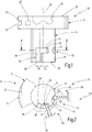
- the interchangeable die 10 comprises a die head 12 which is preferably circular in cross section, as well as a die shank 14 which is also circular in cross section.
- the diameter of the die shank 14 is preferably smaller than that of the die head 12.
- a longitudinal axis is shown with the reference 16.
- FIG. 1 A circumferential portion of the shank is shown in Fig. 1 with the reference 26.
- a shank end face which is remote from the die head 12 is given the reference 28.
- a fastening contour 30 is realized on the die shank 14.
- the fastening contour 30 includes a first circumferential portion 32 which comprises a blocking portion 34.
- the blocking portion 34 can be realized on the die shank 14, for example, by a transverse recess 35 which extends in the direction transversely to the longitudinal axis 16.
- the fastening contour 30 additionally includes a second circumferential portion 36 which is realized as release portion 38.
- the release portion 38 preferably includes a longitudinal recess 39 which extends parallel to the longitudinal axis 16.
- the first circumferential portion 32 and the second circumferential portion 36 connect to one another in the circumferential direction such that a substantially L-shaped contour is produced, as is shown in Fig. 1 .
- the interchangeable die 10 additionally comprises die latching means 42 which are realized, in an aspect that is not part of the present invention, on the die shank 14.
- the die latching means 42 can be formed, for example, by a latching recess 44, as is shown in Fig. 1 and 2 .
- Identification means 46 are preferably realized on the die head 12.
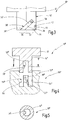
- the tool latching means 60 can interact with the die latching means 42, as is shown in Fig. 2 .
- the latching element 62 engages in a latching recess 44.
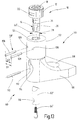
- FIG. 3 A further embodiment of an interchangeable die is shown in Fig. 3 and given the general reference 10'.
- the interchangeable die 10' corresponds in general to the interchangeable die 10. Identical elements are consequently characterized by identical references. It is essentially the differences that are explained below.
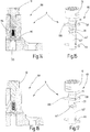
- the die receiving portion 52" includes a shank receiving means 54" which comprises a journal which projects from the bottom and is designed for the purpose of penetrating the blind hole of the die shank 14".
- a fastening contour which is given the reference 56" in Fig. 5 and which, as regards the design, can correspond to the fastening contour 30 of the interchangeable die 10 in Fig. 1 , is realized on the journal.
- the functions of the blocking member 58 and fastening contour 30 are consequently reversed between the interchangeable die 10" and the die receiving portion 52" compared to the embodiment of Fig. 1 .
- the mounting of said latching means 60 is comparatively simple as the shank receiving means 54 is preferably realized as an axially continuous bore in the die holder 68.
Landscapes
- Engineering & Computer Science (AREA)
- Mechanical Engineering (AREA)
- Mounting, Exchange, And Manufacturing Of Dies (AREA)
- Insertion Pins And Rivets (AREA)
Claims (13)
- Auswechselbare Matrize (10) für ein Verbindungswerkzeug (50), wobei die auswechselbare Matrize einen Matrizenkopf (12) aufweist, an dem ein Matrizenmerkmal (18) ausgeführt ist, und einen Matrizenschaft (14) aufweist, der sich von dem Matrizenkopf (12) in eine axiale Richtung (16) erstreckt und in eine Schaftaufnahme (54) eines Matrizenaufnahmeabschnitts (52) eines Verbindungswerkzeugs (50) einsetzbar ist, wobei an der auswechselbaren Matrize (10) eine Befestigungskontur (30) zur Befestigung der auswechselbaren Matrize (10) an dem Verbindungswerkzeug (50) ausgeführt ist,
wobei die Befestigungskontur (30) so ausgeführt ist, dass eine Steck-Dreh-Verbindung zwischen der auswechselbaren Matrize (10) und dem Verbindungswerkzeug (50) hergestellt werden kann,
dadurch gekennzeichnet, dass
an der auswechselbaren Matrize (10) eine Drehmitnahmekontur (22) ausgeführt ist, mit der eine Drehvorrichtung (88) zum Drehen der auswechselbaren Matrize (10) zusammenwirken kann, wobei die Mitnahmekontur (22) durch eine oder zwei Radialnuten auf einem Umfangsabschnitt (24) des Matrizenkopfes (12) ausgebildet ist, wobei sich die eine oder zwei Radialnuten sehnenartig erstrecken, und wobei an der auswechselbaren Matrize (10) Matrizenrastmittel (42) ausgeführt sind, so dass die auswechselbare Matrize (10) in einer Dreh- und/oder Längsposition (B) bezüglich des Verbindungswerkzeugs (50) rastend befestigbar ist, wobei die Matrizenrastmittel auf einer von dem Matrizenkopf (12) entfernten Schaftstirnfläche (28) des Matrizenschaftes (14) ausgeführt sind. - Auswechselbare Matrize nach Anspruch 1, dadurch gekennzeichnet, dass die Befestigungskontur (30) einen ersten Umfangsabschnitt (32) mit einem Blockierabschnitt (34) und einen zweiten Umfangsabschnitt (36) mit einem Löseabschnitt (38) umfasst, derart, dass in einer ersten Drehposition (A) der Matrizenschaft (14) axial in eine Schaftaufnahme (54) einsetzbar ist und/oder axial aus der Schaftaufnahme (54) entfernbar ist und in einer zweiten Drehposition (B) eine in axialer Richtung formschlüssige und/oder kraftschlüssige Verbindung mit dem Verbindungswerkzeug (50) herstellbar ist.
- Auswechselbare Matrize nach Anspruch 2, dadurch gekennzeichnet, dass der Löseabschnitt (38) eine axiale Aussparung (39) im Matrizenschaft (14) umfasst, die sich in axialer Richtung erstreckt, und/oder der Blockierabschnitt (34) eine quer zur axialen Richtung verlaufende Queraussparung (35) im Matrizenschaft (14) umfasst.
- Auswechselbare Matrize nach Anspruch 2 oder 3, dadurch gekennzeichnet, dass der erste und der zweite Umfangsabschnitt (32, 36) in Umfangsrichtung miteinander verbunden sind.
- Auswechselbare Matrize nach einem der Ansprüche 1 - 4, dadurch gekennzeichnet, dass die auswechselbare Matrize (10) mit Identifikationsmitteln (46; 18; 102b; 102c; 102d) bereitgestellt ist, die optisch erkennbar sind, und/oder mit Identifikationsmitteln (102; 102a) bereitgestellt ist, die in der Lage sind, ein charakteristisches akustisches Signal zu erzeugen, das im Falle einer Bewegung der auswechselbaren Matrize (10) relativ zu einem Matrizenaufnahmeabschnitt (52) akustisch erkennbar ist.
- Verbindungswerkzeug (50) mit einer auswechselbaren Matrize (10) nach einem der Ansprüche 1-5, wobei das Verbindungswerkzeug einen Matrizenaufnahmeabschnitt (52) aufweist, der eine Schaftaufnahme (54) zur Aufnahme eines Matrizenschaftes (14) der auswechselbaren Matrize (10) umfasst,
wobei an dem Matrizenaufnahmeabschnitt (52) eine Befestigungsvorrichtung (56) zum Befestigen der auswechselbaren Matrize (10) am Verbindungswerkzeug (50) ausgeführt ist,
wobei die Befestigungsvorrichtung (56) so ausgeführt ist, dass eine Steck-Dreh-Verbindung zwischen der auswechselbaren Matrize (10) und dem Verbindungswerkzeug (50) herstellbar ist. - Verbindungswerkzeug mit einer auswechselbaren Matrize (10) nach Anspruch 6, dadurch gekennzeichnet, dass die Befestigungsvorrichtung (56) des Matrizenaufnahmeabschnitts (52) ein Blockierelement (58) umfasst, das mit einem Blockierabschnitt (34) der auswechselbaren Matrize (10) zusammenwirken kann, um die auswechselbare Matrize (10) in axialer Richtung formschlüssig und/oder kraftschlüssig am Verbindungswerkzeug (50) zu sichern.
- Verbindungswerkzeug mit einer auswechselbaren Matrize (10) nach Anspruch 7, dadurch gekennzeichnet, dass ein Blockierelement (58) in eine Schaftaufnahme (54) des Matrizenaufnahmeabschnitts (52) hineinragt.
- Verbindungswerkzeug mit einer auswechselbaren Matrize (10) nach Anspruch 8 oder 7, dadurch gekennzeichnet, dass ein erstes und/oder ein zweites Blockierelement (108) sehnenförmig in die Schaftaufnahme (54) des Schaftes hineinragt.
- Verbindungswerkzeug mit einer auswechselbaren Matrize (10) nach einem der Ansprüche 6 - 9, gekennzeichnet durch Werkzeugrastmittel (60), die dazu ausgeführt sind, mit Matrizenrastmitteln (42) zusammenzuwirken, um eine im Matrizenaufnahmeabschnitt (52) aufgenommene auswechselbare Matrize (10) in einer Dreh- und/oder Längsposition (B) rastend zu sichern.
- Verbindungswerkzeug mit einer auswechselbaren Matrize (10) nach Anspruch 10, dadurch gekennzeichnet, dass die Werkzeugrastmittel (60) so angeordnet sind, dass sie mit Matrizenrastmitteln (42) zusammenwirken können, die an einer vom Matrizenkopf (12) entfernten Schaftstirnfläche (28) des Matrizenschaftes (14) ausgeführt sind.
- Verbindungswerkzeug mit einer auswechselbaren Matrize (10) nach einem der Ansprüche 6-11, dadurch gekennzeichnet, dass der Matrizenaufnahmeabschnitt (52) auf einem Matrizenhalter (68) ausgeführt ist, der lösbar mit einem Rahmen (72) des Verbindungswerkzeugs (50) verbunden ist.
- Verfahren zum Verbinden mittels eines Verbindungswerkzeugs (50), das einen Matrizenaufnahmeabschnitt (52) für eine auswechselbare Matrize umfasst, wobei das Verfahren die Schritte aufweist- Bewegen des Verbindungswerkzeugs (50) zu einer Übergabestation (76), in der eine auswechselbare Matrize (10) nach einem der Ansprüche 1-5 zwischengelagert wird,- Übergeben der auswechselbaren Matrize (10) in einen Matrizenaufnahmeabschnitt (52) des Verbindungswerkzeugs (50), wobei zwischen dem Matrizenaufnahmeabschnitt (52) und der auswechselbaren Matrize (10) eine axiale Relativbewegung (94) erfolgt und- Durchführen eines Verbindungsprozesses unter Verwendung der auswechselbaren Matrize (10),wenn die auswechselbare Matrize (10) infolge einer relativen Drehung (96) der auswechselbaren Matrize (10) und des Matrizenaufnahmeabschnitts (52) übertragen wird, eine Steck-Dreh-Verbindung zwischen dem Matrizenaufnahmeabschnitt (52) und der auswechselbaren Matrize (10) hergestellt wird, sich die relative Drehung über einen Drehwinkel innerhalb eines Bereichs von 45° bis 135° erstreckt.
Applications Claiming Priority (2)
| Application Number | Priority Date | Filing Date | Title |
|---|---|---|---|
| DE102013021056.9A DE102013021056A1 (de) | 2013-12-18 | 2013-12-18 | Wechselmatrize, Fügewerkzeug und Fügeverfahren |
| PCT/EP2014/076376 WO2015090962A1 (en) | 2013-12-18 | 2014-12-03 | Interchangeable die, joining tool and joining method |
Publications (2)
| Publication Number | Publication Date |
|---|---|
| EP3083100A1 EP3083100A1 (de) | 2016-10-26 |
| EP3083100B1 true EP3083100B1 (de) | 2021-08-25 |
Family
ID=52003780
Family Applications (1)
| Application Number | Title | Priority Date | Filing Date |
|---|---|---|---|
| EP14806273.0A Active EP3083100B1 (de) | 2013-12-18 | 2014-12-03 | Auswechselbare matrize, verbindungswerkzeug und verbindungsverfahren |
Country Status (5)
| Country | Link |
|---|---|
| US (1) | US11020789B2 (de) |
| EP (1) | EP3083100B1 (de) |
| JP (1) | JP6503360B2 (de) |
| DE (2) | DE202013011928U1 (de) |
| WO (1) | WO2015090962A1 (de) |
Families Citing this family (5)
| Publication number | Priority date | Publication date | Assignee | Title |
|---|---|---|---|---|
| DE102015100922A1 (de) | 2015-01-22 | 2016-07-28 | Newfrey Llc | Wechselmatrize, Fügewerkzeug und Fügeverfahren |
| DE102015107337A1 (de) * | 2015-05-11 | 2016-11-17 | Böllhoff Verbindungstechnik GmbH | Matrizenwechsler mit daran angepasster Wechselmatrize und Matrizendom sowie Verfahren zum Entfernen und Einsetzen der Wechselmatrize |
| CN105057546B (zh) * | 2015-07-31 | 2017-10-03 | 南京惠德机械有限公司 | 悬铆铆钉定位装置 |
| GB2563441B (en) | 2017-06-16 | 2022-03-23 | Atlas Copco Ias Uk Ltd | Die changing apparatus |
| DE102018120500A1 (de) * | 2018-08-22 | 2020-02-27 | Tox Pressotechnik Gmbh & Co. Kg | Adapterelement für eine Anbringung eines Matrizenhalters an eine Werkzeugzange |
Family Cites Families (22)
| Publication number | Priority date | Publication date | Assignee | Title |
|---|---|---|---|---|
| US1569136A (en) * | 1925-03-27 | 1926-01-12 | Anthracite Separator Co | Tool holder |
| US1892739A (en) * | 1928-12-13 | 1933-01-03 | Smith J Hugo | Tool and tool holder |
| US2105391A (en) * | 1933-11-14 | 1938-01-11 | Midland Steel Prod Co | Adjustable ram nose for cold riveting fixtures |
| US2773693A (en) * | 1954-05-20 | 1956-12-11 | Windsor N Chittenden | Positive shank-locking means for collet-held cutting tools |
| US3474710A (en) * | 1967-09-01 | 1969-10-28 | Air Mite Devices Inc | Cylinder construction using roll pins |
| GB1280293A (en) * | 1968-10-19 | 1972-07-05 | Wickman Mach Tool Sales Ltd | Coining presses |
| DE2822548C2 (de) * | 1978-05-23 | 1982-11-18 | Sandvik AB, 81181 Sandviken | Werkzeug, insbesondere Bergbaumeißel, mit einem Halteschaft zur Befestigung in einem Aufnahmeteil einer Maschine |
| JPS6413610U (de) * | 1987-07-15 | 1989-01-24 | ||
| US5185992A (en) * | 1991-08-19 | 1993-02-16 | Garcia Roque P | Garden tool expanding assembly |
| US5361473A (en) * | 1992-07-09 | 1994-11-08 | Heavy Duty Marketing Corporation | Rivet setting anvil |
| US5727302A (en) * | 1994-01-31 | 1998-03-17 | Btm Corporation | Die and punch for forming a joint and method of making the die |
| IT1289514B1 (it) * | 1996-12-23 | 1998-10-15 | Ronchi Mario Off Mec | Dispositivo di aggancio rapido di gruppi di applicazione di tappi a contenitori,particolarmente per mandrini di macchine automatiche |
| US5915482A (en) * | 1998-02-26 | 1999-06-29 | Carruthers; Robert B. | Hand tool with interchangeable attachments |
| US6785959B2 (en) * | 2002-08-15 | 2004-09-07 | Btm Corporation | Tool assembly employing a flexible retainer |
| DE10335085B4 (de) | 2003-07-31 | 2016-07-28 | Böllhoff GmbH | Setzwerkzeug mit auswechselbaren Baugruppen |
| DE202006013082U1 (de) | 2005-08-29 | 2006-11-02 | Newfrey Llc, Newark | Rahmen für eine Fügevorrichtung |
| CN101754840B (zh) * | 2007-06-06 | 2013-03-27 | 三星钻石工业株式会社 | 多头搭载划线装置及刀片保持器的自动更换系统 |
| US8683869B2 (en) * | 2008-09-04 | 2014-04-01 | The Boeing Company | Monitoring fastener preload |
| DE102012101894A1 (de) * | 2012-03-06 | 2013-09-12 | Tkr Spezialwerkzeuge Gmbh | Werkzeugverbindung |
| DE102012207651A1 (de) * | 2012-05-08 | 2013-11-14 | Aesculap Ag | Schnellspann-Kupplung |
| DE102012013829B4 (de) * | 2012-07-13 | 2024-03-14 | Newfrey Llc | Stanznietmatrize, Stanznietwerkzeug und Stanznietverfahren |
| US9409241B2 (en) * | 2012-12-13 | 2016-08-09 | Iscar, Ltd. | Cutting tool and replaceable cutting head having spiral driven surfaces therefor |
-
2013
- 2013-12-18 DE DE202013011928.4U patent/DE202013011928U1/de not_active Expired - Lifetime
- 2013-12-18 DE DE102013021056.9A patent/DE102013021056A1/de active Granted
-
2014
- 2014-12-03 EP EP14806273.0A patent/EP3083100B1/de active Active
- 2014-12-03 JP JP2016540490A patent/JP6503360B2/ja active Active
- 2014-12-03 WO PCT/EP2014/076376 patent/WO2015090962A1/en active Application Filing
-
2016
- 2016-06-17 US US15/185,594 patent/US11020789B2/en active Active
Non-Patent Citations (1)
| Title |
|---|
| None * |
Also Published As
| Publication number | Publication date |
|---|---|
| EP3083100A1 (de) | 2016-10-26 |
| WO2015090962A1 (en) | 2015-06-25 |
| DE102013021056A1 (de) | 2015-06-18 |
| JP6503360B2 (ja) | 2019-04-17 |
| DE202013011928U1 (de) | 2014-10-30 |
| JP2016540647A (ja) | 2016-12-28 |
| US11020789B2 (en) | 2021-06-01 |
| US20160288197A1 (en) | 2016-10-06 |
Similar Documents
| Publication | Publication Date | Title |
|---|---|---|
| US11020789B2 (en) | Interchangeable die, joining tool and joining method | |
| US11453045B2 (en) | Interchangeable die transfer station, joining tool system and joining method | |
| US9796014B2 (en) | Tool connection | |
| US9873388B2 (en) | Automotive door trim fastener and molding method | |
| EP1960678B1 (de) | Befestigungsvorrichtung | |
| US6145850A (en) | Diaphragm chuck | |
| US20120067189A1 (en) | Punching tool | |
| RU2615097C2 (ru) | Удерживающая инструмент конструкция | |
| US11077486B2 (en) | Interchangeable die, joining tool and joining method | |
| TWI661881B (zh) | 粉末沖壓組合 | |
| US10056809B2 (en) | System and method for disassembling a drive pinion assembly of starter motor | |
| EP2404068A1 (de) | Drehvorrichtung und antriebseinrichtung | |
| US7179033B2 (en) | Fastener nut for hydroformed parts | |
| US20160305467A1 (en) | 3-in-1 attachment system for liner plates of mills used to grind minerals | |
| US9636740B1 (en) | Micro-stop foot and punch set | |
| WO2014191042A1 (en) | Locking mechanism for a collet assembly and collet assembly including a locking mechanism | |
| US6953198B2 (en) | Short pull-back chuck | |
| US8234963B2 (en) | System and method for mounting dies on a press | |
| US20200164423A1 (en) | Cotter pin forming tool | |
| CN111749961A (zh) | 用于至少暂时相互紧固构件的附接装置 | |
| US20170043459A1 (en) | Compliant fastener starter for simultaneous hardware installation | |
| JP2006061941A (ja) | ブラインドリベット取外し装置、取外し方法、及び取付け構造 |
Legal Events
| Date | Code | Title | Description |
|---|---|---|---|
| PUAI | Public reference made under article 153(3) epc to a published international application that has entered the european phase |
Free format text: ORIGINAL CODE: 0009012 |
|
| 17P | Request for examination filed |
Effective date: 20160617 |
|
| AK | Designated contracting states |
Kind code of ref document: A1 Designated state(s): AL AT BE BG CH CY CZ DE DK EE ES FI FR GB GR HR HU IE IS IT LI LT LU LV MC MK MT NL NO PL PT RO RS SE SI SK SM TR |
|
| AX | Request for extension of the european patent |
Extension state: BA ME |
|
| DAX | Request for extension of the european patent (deleted) | ||
| STAA | Information on the status of an ep patent application or granted ep patent |
Free format text: STATUS: EXAMINATION IS IN PROGRESS |
|
| 17Q | First examination report despatched |
Effective date: 20181114 |
|
| STAA | Information on the status of an ep patent application or granted ep patent |
Free format text: STATUS: EXAMINATION IS IN PROGRESS |
|
| GRAP | Despatch of communication of intention to grant a patent |
Free format text: ORIGINAL CODE: EPIDOSNIGR1 |
|
| STAA | Information on the status of an ep patent application or granted ep patent |
Free format text: STATUS: GRANT OF PATENT IS INTENDED |
|
| INTG | Intention to grant announced |
Effective date: 20210602 |
|
| GRAS | Grant fee paid |
Free format text: ORIGINAL CODE: EPIDOSNIGR3 |
|
| GRAA | (expected) grant |
Free format text: ORIGINAL CODE: 0009210 |
|
| STAA | Information on the status of an ep patent application or granted ep patent |
Free format text: STATUS: THE PATENT HAS BEEN GRANTED |
|
| AK | Designated contracting states |
Kind code of ref document: B1 Designated state(s): AL AT BE BG CH CY CZ DE DK EE ES FI FR GB GR HR HU IE IS IT LI LT LU LV MC MK MT NL NO PL PT RO RS SE SI SK SM TR |
|
| REG | Reference to a national code |
Ref country code: GB Ref legal event code: FG4D |
|
| REG | Reference to a national code |
Ref country code: CH Ref legal event code: EP |
|
| REG | Reference to a national code |
Ref country code: DE Ref legal event code: R096 Ref document number: 602014079697 Country of ref document: DE |
|
| REG | Reference to a national code |
Ref country code: IE Ref legal event code: FG4D Ref country code: AT Ref legal event code: REF Ref document number: 1423266 Country of ref document: AT Kind code of ref document: T Effective date: 20210915 |
|
| REG | Reference to a national code |
Ref country code: LT Ref legal event code: MG9D |
|
| REG | Reference to a national code |
Ref country code: NL Ref legal event code: MP Effective date: 20210825 |
|
| REG | Reference to a national code |
Ref country code: AT Ref legal event code: MK05 Ref document number: 1423266 Country of ref document: AT Kind code of ref document: T Effective date: 20210825 |
|
| PG25 | Lapsed in a contracting state [announced via postgrant information from national office to epo] |
Ref country code: RS Free format text: LAPSE BECAUSE OF FAILURE TO SUBMIT A TRANSLATION OF THE DESCRIPTION OR TO PAY THE FEE WITHIN THE PRESCRIBED TIME-LIMIT Effective date: 20210825 Ref country code: SE Free format text: LAPSE BECAUSE OF FAILURE TO SUBMIT A TRANSLATION OF THE DESCRIPTION OR TO PAY THE FEE WITHIN THE PRESCRIBED TIME-LIMIT Effective date: 20210825 Ref country code: HR Free format text: LAPSE BECAUSE OF FAILURE TO SUBMIT A TRANSLATION OF THE DESCRIPTION OR TO PAY THE FEE WITHIN THE PRESCRIBED TIME-LIMIT Effective date: 20210825 Ref country code: ES Free format text: LAPSE BECAUSE OF FAILURE TO SUBMIT A TRANSLATION OF THE DESCRIPTION OR TO PAY THE FEE WITHIN THE PRESCRIBED TIME-LIMIT Effective date: 20210825 Ref country code: FI Free format text: LAPSE BECAUSE OF FAILURE TO SUBMIT A TRANSLATION OF THE DESCRIPTION OR TO PAY THE FEE WITHIN THE PRESCRIBED TIME-LIMIT Effective date: 20210825 Ref country code: PT Free format text: LAPSE BECAUSE OF FAILURE TO SUBMIT A TRANSLATION OF THE DESCRIPTION OR TO PAY THE FEE WITHIN THE PRESCRIBED TIME-LIMIT Effective date: 20211227 Ref country code: NO Free format text: LAPSE BECAUSE OF FAILURE TO SUBMIT A TRANSLATION OF THE DESCRIPTION OR TO PAY THE FEE WITHIN THE PRESCRIBED TIME-LIMIT Effective date: 20211125 Ref country code: AT Free format text: LAPSE BECAUSE OF FAILURE TO SUBMIT A TRANSLATION OF THE DESCRIPTION OR TO PAY THE FEE WITHIN THE PRESCRIBED TIME-LIMIT Effective date: 20210825 Ref country code: BG Free format text: LAPSE BECAUSE OF FAILURE TO SUBMIT A TRANSLATION OF THE DESCRIPTION OR TO PAY THE FEE WITHIN THE PRESCRIBED TIME-LIMIT Effective date: 20211125 Ref country code: LT Free format text: LAPSE BECAUSE OF FAILURE TO SUBMIT A TRANSLATION OF THE DESCRIPTION OR TO PAY THE FEE WITHIN THE PRESCRIBED TIME-LIMIT Effective date: 20210825 |
|
| PG25 | Lapsed in a contracting state [announced via postgrant information from national office to epo] |
Ref country code: PL Free format text: LAPSE BECAUSE OF FAILURE TO SUBMIT A TRANSLATION OF THE DESCRIPTION OR TO PAY THE FEE WITHIN THE PRESCRIBED TIME-LIMIT Effective date: 20210825 Ref country code: LV Free format text: LAPSE BECAUSE OF FAILURE TO SUBMIT A TRANSLATION OF THE DESCRIPTION OR TO PAY THE FEE WITHIN THE PRESCRIBED TIME-LIMIT Effective date: 20210825 Ref country code: GR Free format text: LAPSE BECAUSE OF FAILURE TO SUBMIT A TRANSLATION OF THE DESCRIPTION OR TO PAY THE FEE WITHIN THE PRESCRIBED TIME-LIMIT Effective date: 20211126 |
|
| PG25 | Lapsed in a contracting state [announced via postgrant information from national office to epo] |
Ref country code: NL Free format text: LAPSE BECAUSE OF FAILURE TO SUBMIT A TRANSLATION OF THE DESCRIPTION OR TO PAY THE FEE WITHIN THE PRESCRIBED TIME-LIMIT Effective date: 20210825 |
|
| PG25 | Lapsed in a contracting state [announced via postgrant information from national office to epo] |
Ref country code: DK Free format text: LAPSE BECAUSE OF FAILURE TO SUBMIT A TRANSLATION OF THE DESCRIPTION OR TO PAY THE FEE WITHIN THE PRESCRIBED TIME-LIMIT Effective date: 20210825 |
|
| REG | Reference to a national code |
Ref country code: DE Ref legal event code: R097 Ref document number: 602014079697 Country of ref document: DE |
|
| PG25 | Lapsed in a contracting state [announced via postgrant information from national office to epo] |
Ref country code: SM Free format text: LAPSE BECAUSE OF FAILURE TO SUBMIT A TRANSLATION OF THE DESCRIPTION OR TO PAY THE FEE WITHIN THE PRESCRIBED TIME-LIMIT Effective date: 20210825 Ref country code: SK Free format text: LAPSE BECAUSE OF FAILURE TO SUBMIT A TRANSLATION OF THE DESCRIPTION OR TO PAY THE FEE WITHIN THE PRESCRIBED TIME-LIMIT Effective date: 20210825 Ref country code: RO Free format text: LAPSE BECAUSE OF FAILURE TO SUBMIT A TRANSLATION OF THE DESCRIPTION OR TO PAY THE FEE WITHIN THE PRESCRIBED TIME-LIMIT Effective date: 20210825 Ref country code: EE Free format text: LAPSE BECAUSE OF FAILURE TO SUBMIT A TRANSLATION OF THE DESCRIPTION OR TO PAY THE FEE WITHIN THE PRESCRIBED TIME-LIMIT Effective date: 20210825 Ref country code: CZ Free format text: LAPSE BECAUSE OF FAILURE TO SUBMIT A TRANSLATION OF THE DESCRIPTION OR TO PAY THE FEE WITHIN THE PRESCRIBED TIME-LIMIT Effective date: 20210825 Ref country code: AL Free format text: LAPSE BECAUSE OF FAILURE TO SUBMIT A TRANSLATION OF THE DESCRIPTION OR TO PAY THE FEE WITHIN THE PRESCRIBED TIME-LIMIT Effective date: 20210825 |
|
| PLBE | No opposition filed within time limit |
Free format text: ORIGINAL CODE: 0009261 |
|
| STAA | Information on the status of an ep patent application or granted ep patent |
Free format text: STATUS: NO OPPOSITION FILED WITHIN TIME LIMIT |
|
| PG25 | Lapsed in a contracting state [announced via postgrant information from national office to epo] |
Ref country code: MC Free format text: LAPSE BECAUSE OF FAILURE TO SUBMIT A TRANSLATION OF THE DESCRIPTION OR TO PAY THE FEE WITHIN THE PRESCRIBED TIME-LIMIT Effective date: 20210825 Ref country code: IT Free format text: LAPSE BECAUSE OF FAILURE TO SUBMIT A TRANSLATION OF THE DESCRIPTION OR TO PAY THE FEE WITHIN THE PRESCRIBED TIME-LIMIT Effective date: 20210825 |
|
| REG | Reference to a national code |
Ref country code: CH Ref legal event code: PL |
|
| 26N | No opposition filed |
Effective date: 20220527 |
|
| GBPC | Gb: european patent ceased through non-payment of renewal fee |
Effective date: 20211203 |
|
| PG25 | Lapsed in a contracting state [announced via postgrant information from national office to epo] |
Ref country code: SI Free format text: LAPSE BECAUSE OF FAILURE TO SUBMIT A TRANSLATION OF THE DESCRIPTION OR TO PAY THE FEE WITHIN THE PRESCRIBED TIME-LIMIT Effective date: 20210825 |
|
| REG | Reference to a national code |
Ref country code: BE Ref legal event code: MM Effective date: 20211231 |
|
| PG25 | Lapsed in a contracting state [announced via postgrant information from national office to epo] |
Ref country code: LU Free format text: LAPSE BECAUSE OF NON-PAYMENT OF DUE FEES Effective date: 20211203 Ref country code: IE Free format text: LAPSE BECAUSE OF NON-PAYMENT OF DUE FEES Effective date: 20211203 Ref country code: GB Free format text: LAPSE BECAUSE OF NON-PAYMENT OF DUE FEES Effective date: 20211203 |
|
| PG25 | Lapsed in a contracting state [announced via postgrant information from national office to epo] |
Ref country code: FR Free format text: LAPSE BECAUSE OF NON-PAYMENT OF DUE FEES Effective date: 20211231 Ref country code: BE Free format text: LAPSE BECAUSE OF NON-PAYMENT OF DUE FEES Effective date: 20211231 |
|
| PG25 | Lapsed in a contracting state [announced via postgrant information from national office to epo] |
Ref country code: LI Free format text: LAPSE BECAUSE OF NON-PAYMENT OF DUE FEES Effective date: 20211231 Ref country code: CH Free format text: LAPSE BECAUSE OF NON-PAYMENT OF DUE FEES Effective date: 20211231 |
|
| PG25 | Lapsed in a contracting state [announced via postgrant information from national office to epo] |
Ref country code: HU Free format text: LAPSE BECAUSE OF FAILURE TO SUBMIT A TRANSLATION OF THE DESCRIPTION OR TO PAY THE FEE WITHIN THE PRESCRIBED TIME-LIMIT; INVALID AB INITIO Effective date: 20141203 |
|
| PG25 | Lapsed in a contracting state [announced via postgrant information from national office to epo] |
Ref country code: CY Free format text: LAPSE BECAUSE OF FAILURE TO SUBMIT A TRANSLATION OF THE DESCRIPTION OR TO PAY THE FEE WITHIN THE PRESCRIBED TIME-LIMIT Effective date: 20210825 |
|
| PGFP | Annual fee paid to national office [announced via postgrant information from national office to epo] |
Ref country code: DE Payment date: 20231010 Year of fee payment: 10 |
|
| PG25 | Lapsed in a contracting state [announced via postgrant information from national office to epo] |
Ref country code: MK Free format text: LAPSE BECAUSE OF FAILURE TO SUBMIT A TRANSLATION OF THE DESCRIPTION OR TO PAY THE FEE WITHIN THE PRESCRIBED TIME-LIMIT Effective date: 20210825 |