EP3082600B1 - Phase retrieval for scanning differential phase contrast systems - Google Patents
Phase retrieval for scanning differential phase contrast systems Download PDFInfo
- Publication number
- EP3082600B1 EP3082600B1 EP14806260.7A EP14806260A EP3082600B1 EP 3082600 B1 EP3082600 B1 EP 3082600B1 EP 14806260 A EP14806260 A EP 14806260A EP 3082600 B1 EP3082600 B1 EP 3082600B1
- Authority
- EP
- European Patent Office
- Prior art keywords
- detector
- phase
- readouts
- phase contrast
- arm
- Prior art date
- Legal status (The legal status is an assumption and is not a legal conclusion. Google has not performed a legal analysis and makes no representation as to the accuracy of the status listed.)
- Not-in-force
Links
- 238000000034 method Methods 0.000 claims description 28
- 230000005855 radiation Effects 0.000 claims description 26
- 238000004590 computer program Methods 0.000 claims description 14
- 238000012545 processing Methods 0.000 claims description 14
- 238000009548 contrast radiography Methods 0.000 claims description 13
- 238000009607 mammography Methods 0.000 claims description 9
- NJPPVKZQTLUDBO-UHFFFAOYSA-N novaluron Chemical compound C1=C(Cl)C(OC(F)(F)C(OC(F)(F)F)F)=CC=C1NC(=O)NC(=O)C1=C(F)C=CC=C1F NJPPVKZQTLUDBO-UHFFFAOYSA-N 0.000 claims description 9
- 238000005259 measurement Methods 0.000 claims description 7
- 238000006073 displacement reaction Methods 0.000 claims description 5
- 230000003993 interaction Effects 0.000 claims description 3
- 238000002591 computed tomography Methods 0.000 claims description 2
- 238000009877 rendering Methods 0.000 claims description 2
- 230000000007 visual effect Effects 0.000 claims description 2
- 238000003384 imaging method Methods 0.000 description 28
- 230000010363 phase shift Effects 0.000 description 19
- 210000000481 breast Anatomy 0.000 description 14
- 230000006870 function Effects 0.000 description 14
- 238000012937 correction Methods 0.000 description 11
- 238000013459 approach Methods 0.000 description 9
- 230000008859 change Effects 0.000 description 9
- 238000010521 absorption reaction Methods 0.000 description 8
- 238000005457 optimization Methods 0.000 description 6
- 230000001419 dependent effect Effects 0.000 description 5
- 230000000694 effects Effects 0.000 description 5
- 230000003190 augmentative effect Effects 0.000 description 3
- 239000011888 foil Substances 0.000 description 3
- LFEUVBZXUFMACD-UHFFFAOYSA-H lead(2+);trioxido(oxo)-$l^{5}-arsane Chemical compound [Pb+2].[Pb+2].[Pb+2].[O-][As]([O-])([O-])=O.[O-][As]([O-])([O-])=O LFEUVBZXUFMACD-UHFFFAOYSA-H 0.000 description 3
- 238000002601 radiography Methods 0.000 description 3
- 230000004044 response Effects 0.000 description 3
- 239000006096 absorbing agent Substances 0.000 description 2
- 230000009471 action Effects 0.000 description 2
- 230000006399 behavior Effects 0.000 description 2
- 230000008901 benefit Effects 0.000 description 2
- 238000004891 communication Methods 0.000 description 2
- 230000006835 compression Effects 0.000 description 2
- 238000007906 compression Methods 0.000 description 2
- 230000005484 gravity Effects 0.000 description 2
- 230000007246 mechanism Effects 0.000 description 2
- 230000009131 signaling function Effects 0.000 description 2
- 238000003860 storage Methods 0.000 description 2
- 210000003813 thumb Anatomy 0.000 description 2
- 230000003936 working memory Effects 0.000 description 2
- 241000204801 Muraenidae Species 0.000 description 1
- 229910000831 Steel Inorganic materials 0.000 description 1
- 238000005452 bending Methods 0.000 description 1
- 239000013256 coordination polymer Substances 0.000 description 1
- 230000001678 irradiating effect Effects 0.000 description 1
- 238000004519 manufacturing process Methods 0.000 description 1
- 239000002184 metal Substances 0.000 description 1
- 238000012544 monitoring process Methods 0.000 description 1
- 230000003287 optical effect Effects 0.000 description 1
- 230000008569 process Effects 0.000 description 1
- 238000003672 processing method Methods 0.000 description 1
- 230000002250 progressing effect Effects 0.000 description 1
- 238000005070 sampling Methods 0.000 description 1
- 239000004065 semiconductor Substances 0.000 description 1
- 230000035945 sensitivity Effects 0.000 description 1
- 239000010959 steel Substances 0.000 description 1
- 239000000758 substrate Substances 0.000 description 1
- 230000005469 synchrotron radiation Effects 0.000 description 1
- 238000003325 tomography Methods 0.000 description 1
Images


Classifications
-
- A—HUMAN NECESSITIES
- A61—MEDICAL OR VETERINARY SCIENCE; HYGIENE
- A61B—DIAGNOSIS; SURGERY; IDENTIFICATION
- A61B6/00—Apparatus or devices for radiation diagnosis; Apparatus or devices for radiation diagnosis combined with radiation therapy equipment
- A61B6/48—Diagnostic techniques
- A61B6/484—Diagnostic techniques involving phase contrast X-ray imaging
-
- A—HUMAN NECESSITIES
- A61—MEDICAL OR VETERINARY SCIENCE; HYGIENE
- A61B—DIAGNOSIS; SURGERY; IDENTIFICATION
- A61B6/00—Apparatus or devices for radiation diagnosis; Apparatus or devices for radiation diagnosis combined with radiation therapy equipment
- A61B6/02—Arrangements for diagnosis sequentially in different planes; Stereoscopic radiation diagnosis
- A61B6/03—Computed tomography [CT]
-
- A—HUMAN NECESSITIES
- A61—MEDICAL OR VETERINARY SCIENCE; HYGIENE
- A61B—DIAGNOSIS; SURGERY; IDENTIFICATION
- A61B6/00—Apparatus or devices for radiation diagnosis; Apparatus or devices for radiation diagnosis combined with radiation therapy equipment
- A61B6/06—Diaphragms
-
- A—HUMAN NECESSITIES
- A61—MEDICAL OR VETERINARY SCIENCE; HYGIENE
- A61B—DIAGNOSIS; SURGERY; IDENTIFICATION
- A61B6/00—Apparatus or devices for radiation diagnosis; Apparatus or devices for radiation diagnosis combined with radiation therapy equipment
- A61B6/42—Arrangements for detecting radiation specially adapted for radiation diagnosis
- A61B6/4291—Arrangements for detecting radiation specially adapted for radiation diagnosis the detector being combined with a grid or grating
-
- A—HUMAN NECESSITIES
- A61—MEDICAL OR VETERINARY SCIENCE; HYGIENE
- A61B—DIAGNOSIS; SURGERY; IDENTIFICATION
- A61B6/00—Apparatus or devices for radiation diagnosis; Apparatus or devices for radiation diagnosis combined with radiation therapy equipment
- A61B6/50—Apparatus or devices for radiation diagnosis; Apparatus or devices for radiation diagnosis combined with radiation therapy equipment specially adapted for specific body parts; specially adapted for specific clinical applications
- A61B6/502—Apparatus or devices for radiation diagnosis; Apparatus or devices for radiation diagnosis combined with radiation therapy equipment specially adapted for specific body parts; specially adapted for specific clinical applications for diagnosis of breast, i.e. mammography
-
- A—HUMAN NECESSITIES
- A61—MEDICAL OR VETERINARY SCIENCE; HYGIENE
- A61B—DIAGNOSIS; SURGERY; IDENTIFICATION
- A61B6/00—Apparatus or devices for radiation diagnosis; Apparatus or devices for radiation diagnosis combined with radiation therapy equipment
- A61B6/58—Testing, adjusting or calibrating thereof
- A61B6/582—Calibration
- A61B6/585—Calibration of detector units
-
- A—HUMAN NECESSITIES
- A61—MEDICAL OR VETERINARY SCIENCE; HYGIENE
- A61B—DIAGNOSIS; SURGERY; IDENTIFICATION
- A61B6/00—Apparatus or devices for radiation diagnosis; Apparatus or devices for radiation diagnosis combined with radiation therapy equipment
- A61B6/58—Testing, adjusting or calibrating thereof
- A61B6/587—Alignment of source unit to detector unit
-
- G—PHYSICS
- G21—NUCLEAR PHYSICS; NUCLEAR ENGINEERING
- G21K—TECHNIQUES FOR HANDLING PARTICLES OR IONISING RADIATION NOT OTHERWISE PROVIDED FOR; IRRADIATION DEVICES; GAMMA RAY OR X-RAY MICROSCOPES
- G21K1/00—Arrangements for handling particles or ionising radiation, e.g. focusing or moderating
- G21K1/02—Arrangements for handling particles or ionising radiation, e.g. focusing or moderating using diaphragms, collimators
- G21K1/04—Arrangements for handling particles or ionising radiation, e.g. focusing or moderating using diaphragms, collimators using variable diaphragms, shutters, choppers
-
- G—PHYSICS
- G21—NUCLEAR PHYSICS; NUCLEAR ENGINEERING
- G21K—TECHNIQUES FOR HANDLING PARTICLES OR IONISING RADIATION NOT OTHERWISE PROVIDED FOR; IRRADIATION DEVICES; GAMMA RAY OR X-RAY MICROSCOPES
- G21K2207/00—Particular details of imaging devices or methods using ionizing electromagnetic radiation such as X-rays or gamma rays
- G21K2207/005—Methods and devices obtaining contrast from non-absorbing interaction of the radiation with matter, e.g. phase contrast
Definitions
- the invention relates to a phase contrast radiography system, to method for processing data supplied by a phase contrast radiography system, to a computer program element, and to a computer readable medium.
- scanning imaging systems such as scanning mammography systems
- the object to be imaged is scanned by movement of the imaging system's detector.
- Some of these scanning imaging systems include an interferometer arrangement that allows grating based phase contrast imaging. See for instance C. Kottler et al, "Grating interferometer based scanning setup for hard x-ray phase contrast imaging", Rev. Sci. Instrum. 78, 043710 (2007 ).
- phase contrast imaging uses a number of techniques referred to as "phase retrieval" which is the task of extracting this refractive information from the detected signals.
- Document WO2013004574 A1 may be considered to disclose a pedestal movable relative to the pedestal in or at the arm, an interferometer assembly including one or more gratings for generating radiation; a detector movable in a scanning motion for receiving said radiation after interaction of said radiation with the interferometer gratings to produce a Moire intensity pattern detectable by the detector across a sequence of readouts when the apparatus is in use.
- phase contrast radiography system of the scanning type comprising:
- the imaging system as proposed herein allows to control the Moiré phase shift instead of depending on the particular amount of shift realized more or less by chance.
- Being able to control the Moiré phase shift has the advantage that detector calibration operation for phase retrieval purposes can be rendered more stable.
- the system designer has better control of how quickly the Moiré pattern drifts, which impacts the stability of a calibration procedure, in particular the one proposed herein.
- the rigidizer is arranged as clamp actuator with at least one pair of jaws for engagement therebetween of the arm and/or the interferometer assembly so as to allow selectably adjusting an amount of the applied force so as to achieve a desired amount of drifting of the Moiré pattern.
- the rigidizer is manually operable.
- the clamp actuator includes a micrometer arrangement with one or more calipers operable to engage the mounting so as to allow a user to selectably adjust in discrete steps an amount of the applied force.
- the rigidizer is formed from a bimetallic sheet attached to the arm and/or the interferometer mounting.
- the system comprises a video signal generator.
- Said video signal generator is operative to supply the sequence of readouts to a display unit during operation of the rigidizer so as to achieve a visual rendering of how the Moiré phase varies with the applied force. This allows the operator to easily select certain preferred rigidity settings.
- a phase contrast radiography apparatus of the scanning type including an interferometer, the method comprising the steps of:
- the method allows a calibration task to be carried our more efficiently.
- a phase retrieval Before a phase retrieval can be done, one must acquire some base line data to learn about calibration parameter, that is, individual characteristics or pixel specific behavior of detector pixels. This has been done in the past by using specific phantom bodies that are placed in the examination region instead of the breast. In the present approach however it is proposed to acquire those base lines in a calibration step solely on the basis of a blank scan.
- the fitting operation includes solving for a pixel displacement ( ⁇ i ) per pixel.
- the signal function model is augmented by the pixel displacements that model imperfections of pixel arrangements in the detector. This further increases the pool of fittable variables thus allowing to model deviations of the typical purely sinusoidal Moiré pattern, as they might occur due to imperfections of the gratings.
- the fitting problem may be formulated into objective function which can then be optimized to accomplish the fitting operation.
- Suitable optimization algorithms include downhill simplex algorithm, conjugate gradients or others may be used.
- the method further comprises the step of:
- the method further comprises the steps of:
- phase contrast imaging radiography apparatus MA is a mammography apparatus of the scanner type but it will be appreciated that the following finds equal application to other scanning radiography imagers for phase contrast imaging for instance, computed tomography CT scanners. It will be appreciated that the term "arm" as used herein corresponds to the rotatable gantry in CT scanner systems.
- the imaging system MA is connected via suitable interface means and across a communication network to a workstation WS.
- workstation WS is a computing system with which a clinician ("user") is able to control operation of the imaging system.
- a display unit or monitor M which is controlled by work station WS and which allows displaying of images that are acquired by the imaging system.
- Workstation WS runs an operating system which in turn controls execution of an image data processor IDP including a number of modules CAL, RECON and CORR whose operation will be explained in more detail below.
- the mammography apparatus MA includes a pedestal PD on which there is mounted an x-ray source XR.
- the x-ray source is rotatable around its focal spot FSP.
- the pedestal PD supports a rotatable gantry with a rotatable hollow arm AR.
- the arm AR is rotatable around the focal spot FSP.
- the arm includes two or more interferometric gratings (a source grating G0, and a ⁇ -phase grating G1 and/or an analyzer grating G2) that together afford the phase imaging capability as will be explained in more detail below.
- G1 may also be a ⁇ /2-phase grating or other suitable phase grating. It is even possible, though not preferred, to use an absorber grating for G1 instead of a phase grating which is the preferred embodiment in medical applications but the absorber version for G1 may be called for in non-medical contexts.
- a detector plate D with a radiation sensitive surface for detecting radiation emitted by source XR.
- the lower part of the arm also includes a gratings mounting GM itself mounted on top of the detector plate.
- the mounting holds one or two (preferably two) gratings G1,G2, with G1 on top of G2, and both above the detector plate, in particular, both gratings mounted above the radiation sensitive surface of the detector plate D.
- Source grating G0 is arranged at the upper end of the arm at an exit window of x-ray source XR.
- a multi collimator arrangement preferably a pre-collimator PRC and a post collimator PSC.
- the post-collimator acts to remove scattering but this component may be left out in certain embodiment, as the G2 grating likewise acts to remove scattering.
- an examination region defined as recess in a housing of the mammography apparatus MA for positioning into a sample object to be imaged, for instance the patient's breast BR.
- a housing of the mammography apparatus MA Part of the mammography apparatus MA housing defines a detector housing whose upper surface serves as a breast support BS on which patient's breast BR is placed during an imaging session, the breast support thereby delimiting from below the examination region.
- a compression plate CP or paddle which can shuttle up and down to compress the breast when placed on the breast support.
- the whole gantry In addition to the arm being rotatable as described above, it is also the whole gantry that is rotatable around a pivot point roughly at the height of the breast support.
- the whole gantry can thereby be tilted to change approach angle to so afford selectively imaging at different views, for instance at CC (cranio-caudal) view (at 12 o'clock position) or MLO (mediolateral oblique) view at about 2 o'clock position.
- Radiation emitted by the source XR enters the arm through an exit window and then passes through the arm towards the detector. In its passage the radiation wave interacts with the first grating G0, also referred to as the source grating G0, to establish coherence.
- the radiation flow is as follows: the radiation wave is collimated by the one or two collimators, then interacts with the breast BR if present in the examination region, thereafter interacts with the two gratings G1,G2 and is then incident on detector plate D to be detected.
- the mammography apparatus MA is operable in two basic modes: in a blank scan mode or in an object scan mode.
- object scan mode which is the usual mode of operation
- the user's breast BR or other sample is placed in the examination region.
- blank scan mode no object or breast is present in the examination region.
- object scan detector readouts are acquired, which can be fed into a reconstructor RECON to compute the phase contrast projection image (and, if desired, a (traditional) absorption contrast image and/or a small scattering ("dark field”) contrast image) in a phase retrieval operation.
- RECON reconstructor RECON
- phase contrast projection image and, if desired, a (traditional) absorption contrast image and/or a small scattering ("dark field") contrast image
- phase reconstruction For the phase reconstruction to work, one needs certain calibration parameter or data, in particular but not only, pixel specific characteristics.
- the calibration data is computed by a calibration module CAL from detector readouts acquired during the blank scan. Operation of calibrator module CAL and reconstructor module RECON will be explained in more detail below at Fig 6 . Both modules are envisaged to run on workstation WS.
- the lower part of the arm (and with it the detector plate and the gratings mounting GM) is motorized to move in the detector housing under breast support BS.
- the very left of Fig 1 shows arm AR in side elevation with its components dependent therefrom and mounted therein or -thereon.
- object or blank scan the arm is moved in synchrony with the x-ray source rotation around its focal spot FSP so that the detector plate together with the gratings G1 and G2 traces out a scanner path SP under the breast BR, if present.
- the scan path is an arc as shown in Figure 1 .
- the mammography apparatus MA is a single or multi slit system.
- the detector plate D's radiation sensitive surface is formed from a single or in general a plurality (for example 8) semi-conductor detector lines deposited on a wafer substrate obtained by a photolithographic process or other suitable detector manufacturing technique.
- those detector lines DL or stripes extend into the paper plane arranged side by side.
- Each detector line is made up of a linear sequence of detector pixels.
- the x-ray beam is essentially split up into a plurality of mini fan beams, with each fan beam irradiating at any one time exactly one of the respective detector lines, namely the one that happens to pass through said fan beam during the detector's motion.
- the detector lines are being exposed to their respective mini fan beam, with each respective mini-fan beam changing direction during the scan. Whilst travelling along the scan path, each detector line will produce the respective readout at different positions on the path.
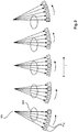
- Fig 2 schematically shows the inherent redundancy (which equals the number of detector lines being on the order of 20 in one embodiment) in the multi-slit scanning approach.
- the detector lines (numbered 1-5) extend into the paper plane transverse to the scanning direction.
- readouts as used herein is meant data collected by pixels along a given detector line when said detector line is at a given position l on the scan path. Put differently, the readouts are per detector line position.
- each detector readout (that is pixel response) can be "spatially stamped" by a tracker (not shown) so each detector readout can be associated with a specific one of a fixed geometrical ray that can be thought of to extend from the focal spot FSP across the examination region to the detector plate D.
- the present mammogram apparatus uses phase contrast imaging in other words the contrast of the images produced by a said imager do not rely solely on absorption as is the case for conventional x-ray systems, but also relies on contrast that results from phase shifts which the radiation wave front experiences when interacting with the matter in the breast.
- the phase shifts or wave distortions are caused by locally different refractive behavior of the imaged matter.
- phase shifts themselves cannot be detected by the detector due to a lack of sufficient spatial resolution. Instead, the phase shifts are derived indirectly by using the interferometric gratings to sample a spatial pattern, a Moiré image pattern that is, detectable after proper setup along detector lines. Moiré patterns occur when the periodicity of the interference fringes is slightly and controllably different from the periodicity of the structures of the analyzer grating G2. This is the approach taught by A. Momose et al in "High-Speed X-ray phase imaging and X-ray phase tomography with Talbot interferometer and white synchrotron radiation" in Optics Express, Vol 17, No 15, pp12540, (2009 ).
- collimators and gratings are carefully tuned in respect of the detector lines to a desired Talbot distance of desired order by aligning in orientation and distance. See for instance, see T. Donath et al in "Inverse geometry for grating-based x-ray phase-contrast imaging," J. Appl. Phys. 106, 054703 (2009 ).
- this Talbot set-up By then carefully de-tuning this Talbot set-up, for instance by varying the distance between the source grating G0 and the ⁇ -phase grating G1 (or ⁇ /2-phase grating) a reference Moiré pattern emerges along the detector lines during a blank scan. How this reference Moiré pattern is detected depends on the local characteristics of the various detector pixels as mentioned earlier in connection with the calibration data. The proposition is then, that an intervening object BR in an object scan will disturb this Moiré pattern. The disturbance shows as a phase shift of the reference Moiré pattern and this Moiré pattern phase shift is known to be related to the local gradient of the phase shift experienced by the wave when passing through object. So we need to know the phase (“reference phase”) of the Moiré pattern to be able to perform phase retrieval. Determination of said Moiré phase reference is part of the calibration task summarized above.
- phase stepping In previous phase contrast imaging approaches, a fixed interferometric set-up has been used wherein, for phase retrieval purposes, one of the gratings is moved relative to the other to sample an interference pattern by "phase stepping". See for instance T. Weitkamp et al in "Optics Express", vol 13, No 16, pp 6296-6304 (2005 ). However, in the present approach no such phase stepping is needed. Instead, the phase retrieval operation is based on the scanning motion (together with the gratings motion) that is used herein to analyze the Moiré pattern fringes as recorded by detector during its motion to derive desired phase contrast information (and, incidentally, also the absorptive or dark field image which may be of use). So the detector motion serves to functions: first, it allows obtaining the full field of view- this was the original purpose - and second, the motion is harnessed for phase retrieval purposes.
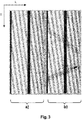
- the left pane in Figure 3a shows a readout time l versus detector line measurements where k indicates pixel positions in a certain single line. There is a drift across the various readout instances as can be seen by the dark and white bands which run slanted across the pane defined by the plurality of readouts as per Fig 3 .
- the right hand side pane in Figure 3b shows the same wide drift during object scan and the remarkable fact that the drift reproduces well for blank and object scan. About half way through along the readout direction l there can be seen a "kink" which indicates the instance when the scan arm AR moved across the horizontal position. Applicants observed that this Moiré drift can be attributed to mechanical imperfections in the rigidity of the scan arm AR.
- the back bands demark the footprint of an ASIC or other electronic component.
- the presence of those black bands is exemplary only as in alternative embodiments the readout electronics component is not positioned on the detector lines.
- the signal model function as per (1) includes two parameters, namely A k and V k , which are characteristic for the detector and the local properties of the gratings.
- the parameter A k relates to the product of the incoming intensity and the sensitivity of the detector pixel k
- the parameter V k relates to the local fringe visibility for the detector pixel k . Since these two parameters are detector and grating specific parameters, they do not change with the readout index l so instead they depend only on pixel position k. Changes of the fringe pattern during readout are completely attributed to a simple phase shift of the fringe pattern, represented by the readout-specific phases ⁇ l .
- the model contains also the global parameter ⁇ , related to the spatial frequency of the Moiré fringes as detectable along the detector lines.
- ⁇ the global parameter ⁇ , related to the spatial frequency of the Moiré fringes as detectable along the detector lines.
- all phases ⁇ l would be the same.
- the amount of drift is more or less at the whim of the instant configuration of the imager's arm AR and a certain given rigidity which is usually beyond the system designer's control. It is proposed herein to change this and to furnish the mammography apparatus MA with mechanical means, a rigidizer RGD, to be able to control the rigidity in particular of the scanner arm AR and all the gratings mountings GM by suitable mechanical action.
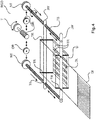
- Figure 4 shows one arrangement for controlling directly the stiffness of the gratings mounting GM as arranged in the scanner arm AR.
- Figure 4 shows a perspective view on the gratings mounting GM which in one embodiment is a frame (made from steel in one embodiment) mounted on detector plate D.
- the arrangement of rigidizer RGD can be thought of as a lead screw arrangement.
- a guide nut NT is mounted on respective ones of the threaded shafts and can be advanced along the shaft towards respective ones of the jaws JW by operation of a suitable gearing arrangement GR that acts to inter-mesh said nuts and with a thumb wheel T which is user operable.
- GR gearing arrangement
- the user turns the thumb wheel T and thereby effects advancing the engager nuts NT along their respective threaded shaft to force each into engagement with the respective ones of the jaws JW. This allows the user to apply a force onto the cage GM and essentially compress same thereby changing the rigidity of the grating mounting GM.
- a ratchet mechanism interposed between the gear meshing and the thump wheel T to ensure that the force applied to cage GM is at discrete steps only and cannot be changed continuously. This ensures higher reproducibility of a certain Moiré pattern that is associated with a certain application of force.
- track arrangements TR formed in cage GM in which the gratings G1 or G2 (in the Figure, merely one grating G1 is shown for ease of representation) are slideably received, not unlike slides in a slide projector.
- the rigidizer that directly acts on the grating mounting cage GM can take numerous forms and Figure 4 is merely one embodiment.
- a motorized version is also envisaged with a controller that acts or varies the rigidity in response to an input.
- both nuts NT move in synchrony when operating the thumbscrew T.
- each nut can be actuated independently from the other, which applies to both, the manual and motorized version.
- a micrometer arrangement is also envisaged, where a micrometer type device is positioned so that the cage GM comes to lie between the two calipers. Operating the micrometer's thimble advances the spindle and the gratings cage GM is engaged between the calipers to apply a compression action thereon.
- a suitable ratchet type mechanism can be arranged so as to ensure that the application of the force is constrained in a metered, graduated fashion into discrete steps.
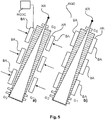
- Figure 5 shows an alternative embodiment which can be used instead or in addition to the embodiment in Figure 4 .
- the rigidizer RGD acts indirectly on the grating mountings cage by having actuators BA arranged on either side of the arm AR.
- the rigidizer acts directly on the arm to change the arm rigidity.
- Figure 5a shows actuators BA, for instance bar elements arranged in a suitable number (one or more - three are shown as a non-limiting example) of pairs along the length of the arm AR.
- actuation of actuators BA Upon actuation of actuators BA, a force is applied on the arm AR at respective locations to thereby change the overall rigidity of the arm AR.
- the different sets of actuators are either operable in synchrony or may also be operable independently thereby affording a higher degree of customized ability of the rigidity.
- bimetallic foil is used.
- One side of said foil is attached by bonding to the arm AR, either one the inside or outside.
- the arm is essentially "wrapped" in or lined with said foil.
- the bimetallic metal is then heated to various temperatures (before the scan due to account for a certain thermal inertial) which will then either increase or decrease the susceptibility of the arm to bending due to changes in gravitational torques during the scan.
- a rigidizer controller RGDC operates rigidizer RGD automatically. For instance, as observed earlier in connection with Fig 2 , the amount of Moiré pattern phase shift is an indicator for the rigidity or lack thereof. The readouts as per Fig 2 for a certain detector line can be fed into controller RGDC. Controller RGDC then operates actuators BA to dynamically increase/decrease rigidly in dependence on the detected Moiré phase drift amount as per the detector readings. A large change will attract an application of a larger force to maintain rigidity whereas force application can be relaxed otherwise. Controller may thus operate in a closed loop manner to increase or decrease force to maintain a desired Moiré pattern shift or to ensure that this shift remains below a user-definable threshold.
- rigidizer's operation may be linked to certain positions of the detector plate on path SP. For instance, as observed earlier, there is a kink in phase Moiré change at passage of arm AR through the vertical position. This may be an instant then when a larger rigidity is called for. Operation of controller RGDC may therefore be programmed to such that force is applied in response to the arm's AR position along its path SP in particular force is applied when arm assumes a vertical position.
- the respective readout during operation of the rigidizer are rendered for view on a screen which allows the user to directly examine how the Moiré pattern changes whilst varying the force.
- a graphic representation of the moray pattern drift is shown in Figure 3 and can be rendered for view on a screen.
- the calibration data is acquired by having the detector readout in a bank scan processed by a calibration unit CAL.
- the calibration data is then passed to re-constructor RECON, which then operates to perform a phase retrieval step to produce inter alia the phase contrast image and/or an absorption and/or a scatter image.
- step 605 the rigidity of the arm AR and/or the gratings mounting GM is adjusted to the desired degree of rigidity.
- a blank scan is then carried out with the arm now having the desired rigidity.
- Each pixel responds by issuing an electrical signal that depends on the radiation intensity seen by the respective pixel at an instance and/or position along the scan path.
- the collection of these electrical signals is then A/D converted by data acquisition unit DAS into numerical form and then passed on to calibrator CAL as a respective detector readouts. It has been observed that a certain minimum number of pixels per detector line is required to capture the Moiré pattern. A pixel count of approximately 200 or 250 (in particular 256) has been found to work well.
- the optimization may be performed in one embodiment in several steps in an iterative coordinate decent method, which splits the large problem into several smaller sub-problems, which are easier to solve.
- the output at fitting step S615 is a triple of calibration parameters for each pixel k of the respective detector line.
- the calibration triple for each pixel on a given detector line comprises two pixel dependent parameters: i) the input intensity A k , and ii) the visibility V k .
- a different, more detailed signal model function is used instead.
- the model function used in Eq.1 is simply a pure sinusoidal variation of the Moiré fringe. If the gratings of the interferometer are not perfectly flat, there might be deviations from this ideal model. More complex models, possibly with heuristic parameters can be used to model the measured data in such a situation.
- the model is a refinement over the model as per equation 1 which allows for deviations from the perfect sinusoidal shape by assuming that the detector pixels are displaced along their respective detector line by a fixed fraction ⁇ k of the nominal pixel spacing (which is in one embodiment in the order of 50 microns but this a non-limiting example only).
- ⁇ k the nominal pixel spacing
- this is only an "interpretation" of parameter ⁇ k , which does not necessarily represent the true cause of the deviation.
- a grating imperfection may lead to a phase shift of the Moiré pattern, which can be well represented by the parameter ⁇ k , too.
- step 620a an object scan is carried out. Again the detector readouts are passed on, but this time to reconstructor RECON via a switch SW.
- phase retrieval step to be carried in step 625 it may be worth observing that calibration module CAL operation was not encumbered by the redundancy in respective of same geometrical array as observed earlier.
- step S620a the previous computations through to step S620a proceeded in a detector-line-wise fashion, where each triple of calibration parameters got assigned to each pixel k per readout l .
- This "processing line-wise" context is no longer applicable for the phase retrieval step. Instead, the processing context for phase retrieval is all data belonging to the same geometrical ray.
- the accumulated phase shifts then form a projection point that serves as image contrast.
- This collection-per-geometrical ray operation can be done by operation of a data grabber that evaluates the "spatial stamps" for each readout and collects the pixel-readouts into groups per geometrical array.
- Phase retrieval is performed for each geometrical ray independently.
- the actual measurements of the pixels obtained during the object scan are denoted by g i .
- the influence of the object BR onto the measured data is modeled by the three image parameters B (the attenuation of the x-ray beam), S (the loss of visibility of the interference pattern due to small angle scattering, this is also called the dark field), and ⁇ the beam the phase shift due to refraction which corresponds (after a possible scaling) to the actual phase contrast image to the reconstructed.
- the other image parameters for the absorption image and the dark field may or may not be required in further processing or display.
- the output at step S620 is, for each geometrical ray, a respective image point that collectively (taken over all geometrical rays) define the resulting images for the attenuation, loss of visibility and differential phase.
- step S630 the resulting images for attenuation and/or loss of visibility and/or differential phase are then output and can then be rendered for display on monitor MT or otherwise image processed.
- artifact correction step 620b implemented by correction module CORR.
- Applicants has observed on occasion certain artifacts in the reconstructed image. More specifically, the main structure of the artifacts follows still the Moiré pattern. The origin of these artifacts is the fact that even with the augmented signal model as per Eq. (4), the blank scan is not modeled with sufficient accuracy. To combat these drift artifacts, a concept of artifact cancellation is proposed herein as outlined in the following. It has been further observed that the artifacts that present themselves in the differential phase image obtained in particular with the augmented model as per Eq. (4) are well reproduced if we use the blank scan as an object scan.
- the calibration parameters themselves are treated in step S20b as if they were obtained from an "object" scan by performing a phase retrieval operation analogous to step S625.
- the calibration parameter triple is grouped by grabber into groups per geometrical ray as has been explained earlier for the "real" phase retrieval step S625 based on object scan data.
- the respective images of absorption, dark field and phase shift can be considered respective correction images; that is an absorption correction image, a dark field correction image and a phase contrast correction image.
- the artifact image is slightly low-pass filtered in scan direction.
- the components of image data processing system IDP as per Figure 1 all run on a single computing system like the imaging apparatus' MA workstation WS.
- an at least partly distributed architecture is likewise envisaged herein where one or more of the components are located remotely and are connected with each other and/or with the image data processing system IDP in a suitable communication network.
- image data processing system IPD (or at least some of its components) is arranged as a dedicated FPGA or as a hardwired (standalone) chip.
- image data processing system may be programmed in a suitable scientific computing platform such as Matlab® and may be translated into C++ or C routines suitable to run on a computing system (such as the imager's workstation WS).
- a suitable scientific computing platform such as Matlab®
- C++ or C routines suitable to run on a computing system (such as the imager's workstation WS).
- a computer program or a computer program element is provided that is characterized by being adapted to execute the method steps of the method according to one of the preceding embodiments, on an appropriate system.
- the computer program element might therefore be stored on a computer unit, which might also be part of an embodiment of the present invention.
- This computing unit may be adapted to perform or induce a performing of the steps of the method described above. Moreover, it is adapted to operate the components of the above-described apparatus.
- the computing unit can be adapted to operate automatically and/or to execute the orders of a user.
- a computer program may be loaded into a working memory of a data processor.
- the data processor may thus be equipped to carry out the method of the invention.
- the computer program element might be able to provide all necessary steps to fulfill the procedure of an exemplary embodiment of the method as described above.
- a computer readable medium such as a CD-ROM
- the computer readable medium has a computer program element stored on it which computer program element is described by the preceding section.
- a computer program may be stored and/or distributed on a suitable medium, such as an optical storage medium or a solid-state medium supplied together with or as part of other hardware, but may also be distributed in other forms, such as via the internet or other wired or wireless telecommunication systems.
- a suitable medium such as an optical storage medium or a solid-state medium supplied together with or as part of other hardware, but may also be distributed in other forms, such as via the internet or other wired or wireless telecommunication systems.
- the computer program may also be presented over a network like the World Wide Web and can be downloaded into the working memory of a data processor from such a network.
- a medium for making a computer program element available for downloading is provided, which computer program element is arranged to perform a method according to one of the previously described embodiments of the invention.
Landscapes
- Health & Medical Sciences (AREA)
- Life Sciences & Earth Sciences (AREA)
- Engineering & Computer Science (AREA)
- Medical Informatics (AREA)
- Physics & Mathematics (AREA)
- High Energy & Nuclear Physics (AREA)
- Radiology & Medical Imaging (AREA)
- Molecular Biology (AREA)
- Veterinary Medicine (AREA)
- Nuclear Medicine, Radiotherapy & Molecular Imaging (AREA)
- Optics & Photonics (AREA)
- Pathology (AREA)
- Public Health (AREA)
- Biomedical Technology (AREA)
- Heart & Thoracic Surgery (AREA)
- Biophysics (AREA)
- Surgery (AREA)
- Animal Behavior & Ethology (AREA)
- General Health & Medical Sciences (AREA)
- Spectroscopy & Molecular Physics (AREA)
- General Engineering & Computer Science (AREA)
- Dentistry (AREA)
- Oral & Maxillofacial Surgery (AREA)
- Apparatus For Radiation Diagnosis (AREA)
Priority Applications (1)
| Application Number | Priority Date | Filing Date | Title |
|---|---|---|---|
| EP14806260.7A EP3082600B1 (en) | 2013-12-17 | 2014-12-03 | Phase retrieval for scanning differential phase contrast systems |
Applications Claiming Priority (3)
| Application Number | Priority Date | Filing Date | Title |
|---|---|---|---|
| EP13197763 | 2013-12-17 | ||
| PCT/EP2014/076325 WO2015090949A1 (en) | 2013-12-17 | 2014-12-03 | Phase retrieval for scanning differential phase contrast systems |
| EP14806260.7A EP3082600B1 (en) | 2013-12-17 | 2014-12-03 | Phase retrieval for scanning differential phase contrast systems |
Publications (2)
| Publication Number | Publication Date |
|---|---|
| EP3082600A1 EP3082600A1 (en) | 2016-10-26 |
| EP3082600B1 true EP3082600B1 (en) | 2018-03-28 |
Family
ID=49911203
Family Applications (1)
| Application Number | Title | Priority Date | Filing Date |
|---|---|---|---|
| EP14806260.7A Not-in-force EP3082600B1 (en) | 2013-12-17 | 2014-12-03 | Phase retrieval for scanning differential phase contrast systems |
Country Status (6)
| Country | Link |
|---|---|
| US (1) | US10172580B2 (zh) |
| EP (1) | EP3082600B1 (zh) |
| JP (1) | JP6396472B2 (zh) |
| CN (1) | CN105828716B (zh) |
| RU (1) | RU2677763C1 (zh) |
| WO (1) | WO2015090949A1 (zh) |
Families Citing this family (8)
| Publication number | Priority date | Publication date | Assignee | Title |
|---|---|---|---|---|
| US10542943B2 (en) * | 2015-01-06 | 2020-01-28 | Koninklijke Philips N.V. | Scanning mammography X-ray system with movement adaption mechanism |
| CN107567640B (zh) | 2015-05-07 | 2022-04-05 | 皇家飞利浦有限公司 | 用于扫描暗场和相位对比成像的射束硬化校正 |
| EP3383273B1 (en) * | 2015-12-01 | 2021-05-12 | Koninklijke Philips N.V. | Apparatus for x-ray imaging an object |
| JP6613988B2 (ja) * | 2016-03-30 | 2019-12-04 | コニカミノルタ株式会社 | 放射線撮影システム |
| EP3403581A1 (en) | 2017-05-15 | 2018-11-21 | Koninklijke Philips N.V. | Grid-mounting device for slit-scan differential phase contrast imaging |
| EP3446630A1 (en) * | 2017-08-23 | 2019-02-27 | Koninklijke Philips N.V. | Device and method for phase stepping in phase contrast image acquisition |
| EP3459461A1 (en) | 2017-09-25 | 2019-03-27 | Koninklijke Philips N.V. | X-ray imaging reference scan |
| JP7069670B2 (ja) * | 2017-12-04 | 2022-05-18 | コニカミノルタ株式会社 | X線撮影システム |
Family Cites Families (15)
| Publication number | Priority date | Publication date | Assignee | Title |
|---|---|---|---|---|
| US5291539A (en) | 1992-10-19 | 1994-03-01 | General Electric Company | Variable focussed X-ray grid |
| SE0201295L (sv) * | 2002-04-30 | 2003-07-22 | Arcoma Ab | Rasterhållaranordning, samt röntgendiagnostiksystem innefattande sådan |
| JP2004313546A (ja) * | 2003-04-17 | 2004-11-11 | Shimadzu Corp | X線撮影装置 |
| CN101011256A (zh) | 2006-02-01 | 2007-08-08 | 西门子公司 | 通过x射线无破坏地分析检查对象的方法和测量装置 |
| DE102006037256B4 (de) * | 2006-02-01 | 2017-03-30 | Paul Scherer Institut | Fokus-Detektor-Anordnung einer Röntgenapparatur zur Erzeugung projektiver oder tomographischer Phasenkontrastaufnahmen sowie Röntgensystem, Röntgen-C-Bogen-System und Röntgen-CT-System |
| CN103876761B (zh) | 2008-10-29 | 2016-04-27 | 佳能株式会社 | X射线成像装置和x射线成像方法 |
| JP5702586B2 (ja) * | 2010-02-04 | 2015-04-15 | 富士フイルム株式会社 | 放射線撮影システム |
| JP5438649B2 (ja) | 2010-03-26 | 2014-03-12 | 富士フイルム株式会社 | 放射線撮影システム及び位置ずれ判定方法 |
| WO2012042924A1 (ja) * | 2010-09-29 | 2012-04-05 | コニカミノルタエムジー株式会社 | 医用画像表示方法及び医用画像表示システム |
| CN103188996B (zh) | 2010-10-29 | 2015-06-24 | 富士胶片株式会社 | 放射线照相相衬成像设备 |
| JP2012125343A (ja) * | 2010-12-14 | 2012-07-05 | Fujifilm Corp | 放射線撮影システム及び画像処理方法 |
| SE535571C2 (sv) * | 2011-03-17 | 2012-09-25 | Hållare för cylindrisk krökning av ett röntgenraster | |
| CN103648388B (zh) | 2011-07-04 | 2017-05-03 | 皇家飞利浦有限公司 | 相位对比度成像设备 |
| WO2014206841A1 (en) | 2013-06-28 | 2014-12-31 | Koninklijke Philips N.V. | Correction in phase contrast imaging |
| WO2015044238A1 (en) | 2013-09-27 | 2015-04-02 | Koninklijke Philips N.V. | Reference phase determination in scanning differential-phase-contrast-imaging |
-
2014
- 2014-12-03 US US15/104,816 patent/US10172580B2/en not_active Expired - Fee Related
- 2014-12-03 WO PCT/EP2014/076325 patent/WO2015090949A1/en active Application Filing
- 2014-12-03 EP EP14806260.7A patent/EP3082600B1/en not_active Not-in-force
- 2014-12-03 JP JP2016539315A patent/JP6396472B2/ja not_active Expired - Fee Related
- 2014-12-03 CN CN201480069101.2A patent/CN105828716B/zh not_active Expired - Fee Related
- 2014-12-03 RU RU2016128740A patent/RU2677763C1/ru active
Also Published As
| Publication number | Publication date |
|---|---|
| WO2015090949A1 (en) | 2015-06-25 |
| JP6396472B2 (ja) | 2018-09-26 |
| EP3082600A1 (en) | 2016-10-26 |
| JP2016540587A (ja) | 2016-12-28 |
| RU2016128740A (ru) | 2018-01-23 |
| US20160317112A1 (en) | 2016-11-03 |
| US10172580B2 (en) | 2019-01-08 |
| CN105828716A (zh) | 2016-08-03 |
| RU2677763C1 (ru) | 2019-01-21 |
| CN105828716B (zh) | 2019-05-10 |
Similar Documents
| Publication | Publication Date | Title |
|---|---|---|
| EP3082600B1 (en) | Phase retrieval for scanning differential phase contrast systems | |
| CN107567640B (zh) | 用于扫描暗场和相位对比成像的射束硬化校正 | |
| JP5331940B2 (ja) | 放射線撮影システム及び放射線画像生成方法 | |
| JP6383355B2 (ja) | 画像診断システム及び作動方法 | |
| US9842414B2 (en) | Monochromatic attenuation contrast image generation by using phase contrast CT | |
| US20170035378A1 (en) | Material differentiation with phase contrast imaging | |
| CN104582573B (zh) | 在微分相位对比成像中对齐源光栅到相位光栅距离以用于多阶相位调谐 | |
| US20160242714A1 (en) | Large fov phase contrast imaging based on detuned configuration including acquisition and reconstruction techniques | |
| JP5238786B2 (ja) | 放射線撮影装置及び放射線撮影システム | |
| JP5343065B2 (ja) | 放射線撮影システム | |
| JP2012090944A (ja) | 放射線撮影システム及び放射線撮影方法 | |
| JP2012090945A (ja) | 放射線検出装置、放射線撮影装置、放射線撮影システム | |
| US20120250972A1 (en) | Radiographic system and radiographic method | |
| JP2012115576A (ja) | 放射線画像検出装置、放射線撮影装置、放射線撮影システム | |
| JP6816144B2 (ja) | 被検体をx線撮像する装置 | |
| WO2015044238A1 (en) | Reference phase determination in scanning differential-phase-contrast-imaging | |
| JP2011206490A (ja) | 放射線撮影システム及び放射線撮影方法 | |
| WO2012169426A1 (ja) | 放射線撮影システム | |
| JP2022524071A (ja) | X線暗視野画像、位相コントラスト画像及び減衰トモシンセシス画像を取得するシステム | |
| JP2014155509A (ja) | 放射線撮影システム | |
| WO2012147528A1 (ja) | 放射線撮影装置及びその制御方法 | |
| JP2011206489A (ja) | 放射線撮影システム及び放射線撮影方法 | |
| WO2012133553A1 (ja) | 放射線撮影システム及び放射線撮影方法 |
Legal Events
| Date | Code | Title | Description |
|---|---|---|---|
| PUAI | Public reference made under article 153(3) epc to a published international application that has entered the european phase |
Free format text: ORIGINAL CODE: 0009012 |
|
| 17P | Request for examination filed |
Effective date: 20160718 |
|
| AK | Designated contracting states |
Kind code of ref document: A1 Designated state(s): AL AT BE BG CH CY CZ DE DK EE ES FI FR GB GR HR HU IE IS IT LI LT LU LV MC MK MT NL NO PL PT RO RS SE SI SK SM TR |
|
| AX | Request for extension of the european patent |
Extension state: BA ME |
|
| DAX | Request for extension of the european patent (deleted) | ||
| GRAP | Despatch of communication of intention to grant a patent |
Free format text: ORIGINAL CODE: EPIDOSNIGR1 |
|
| INTG | Intention to grant announced |
Effective date: 20171016 |
|
| GRAS | Grant fee paid |
Free format text: ORIGINAL CODE: EPIDOSNIGR3 |
|
| GRAA | (expected) grant |
Free format text: ORIGINAL CODE: 0009210 |
|
| AK | Designated contracting states |
Kind code of ref document: B1 Designated state(s): AL AT BE BG CH CY CZ DE DK EE ES FI FR GB GR HR HU IE IS IT LI LT LU LV MC MK MT NL NO PL PT RO RS SE SI SK SM TR |
|
| REG | Reference to a national code |
Ref country code: GB Ref legal event code: FG4D |
|
| REG | Reference to a national code |
Ref country code: CH Ref legal event code: EP |
|
| REG | Reference to a national code |
Ref country code: AT Ref legal event code: REF Ref document number: 982648 Country of ref document: AT Kind code of ref document: T Effective date: 20180415 |
|
| REG | Reference to a national code |
Ref country code: IE Ref legal event code: FG4D |
|
| REG | Reference to a national code |
Ref country code: DE Ref legal event code: R096 Ref document number: 602014023084 Country of ref document: DE |
|
| REG | Reference to a national code |
Ref country code: DE Ref legal event code: R084 Ref document number: 602014023084 Country of ref document: DE |
|
| REG | Reference to a national code |
Ref country code: GB Ref legal event code: 746 Effective date: 20180515 |
|
| PG25 | Lapsed in a contracting state [announced via postgrant information from national office to epo] |
Ref country code: HR Free format text: LAPSE BECAUSE OF FAILURE TO SUBMIT A TRANSLATION OF THE DESCRIPTION OR TO PAY THE FEE WITHIN THE PRESCRIBED TIME-LIMIT Effective date: 20180328 Ref country code: LT Free format text: LAPSE BECAUSE OF FAILURE TO SUBMIT A TRANSLATION OF THE DESCRIPTION OR TO PAY THE FEE WITHIN THE PRESCRIBED TIME-LIMIT Effective date: 20180328 Ref country code: FI Free format text: LAPSE BECAUSE OF FAILURE TO SUBMIT A TRANSLATION OF THE DESCRIPTION OR TO PAY THE FEE WITHIN THE PRESCRIBED TIME-LIMIT Effective date: 20180328 Ref country code: NO Free format text: LAPSE BECAUSE OF FAILURE TO SUBMIT A TRANSLATION OF THE DESCRIPTION OR TO PAY THE FEE WITHIN THE PRESCRIBED TIME-LIMIT Effective date: 20180628 |
|
| REG | Reference to a national code |
Ref country code: NL Ref legal event code: MP Effective date: 20180328 |
|
| REG | Reference to a national code |
Ref country code: LT Ref legal event code: MG4D |
|
| PG25 | Lapsed in a contracting state [announced via postgrant information from national office to epo] |
Ref country code: BG Free format text: LAPSE BECAUSE OF FAILURE TO SUBMIT A TRANSLATION OF THE DESCRIPTION OR TO PAY THE FEE WITHIN THE PRESCRIBED TIME-LIMIT Effective date: 20180628 Ref country code: SE Free format text: LAPSE BECAUSE OF FAILURE TO SUBMIT A TRANSLATION OF THE DESCRIPTION OR TO PAY THE FEE WITHIN THE PRESCRIBED TIME-LIMIT Effective date: 20180328 Ref country code: RS Free format text: LAPSE BECAUSE OF FAILURE TO SUBMIT A TRANSLATION OF THE DESCRIPTION OR TO PAY THE FEE WITHIN THE PRESCRIBED TIME-LIMIT Effective date: 20180328 Ref country code: GR Free format text: LAPSE BECAUSE OF FAILURE TO SUBMIT A TRANSLATION OF THE DESCRIPTION OR TO PAY THE FEE WITHIN THE PRESCRIBED TIME-LIMIT Effective date: 20180629 Ref country code: LV Free format text: LAPSE BECAUSE OF FAILURE TO SUBMIT A TRANSLATION OF THE DESCRIPTION OR TO PAY THE FEE WITHIN THE PRESCRIBED TIME-LIMIT Effective date: 20180328 |
|
| PG25 | Lapsed in a contracting state [announced via postgrant information from national office to epo] |
Ref country code: EE Free format text: LAPSE BECAUSE OF FAILURE TO SUBMIT A TRANSLATION OF THE DESCRIPTION OR TO PAY THE FEE WITHIN THE PRESCRIBED TIME-LIMIT Effective date: 20180328 Ref country code: RO Free format text: LAPSE BECAUSE OF FAILURE TO SUBMIT A TRANSLATION OF THE DESCRIPTION OR TO PAY THE FEE WITHIN THE PRESCRIBED TIME-LIMIT Effective date: 20180328 Ref country code: PL Free format text: LAPSE BECAUSE OF FAILURE TO SUBMIT A TRANSLATION OF THE DESCRIPTION OR TO PAY THE FEE WITHIN THE PRESCRIBED TIME-LIMIT Effective date: 20180328 Ref country code: NL Free format text: LAPSE BECAUSE OF FAILURE TO SUBMIT A TRANSLATION OF THE DESCRIPTION OR TO PAY THE FEE WITHIN THE PRESCRIBED TIME-LIMIT Effective date: 20180328 Ref country code: ES Free format text: LAPSE BECAUSE OF FAILURE TO SUBMIT A TRANSLATION OF THE DESCRIPTION OR TO PAY THE FEE WITHIN THE PRESCRIBED TIME-LIMIT Effective date: 20180328 Ref country code: AL Free format text: LAPSE BECAUSE OF FAILURE TO SUBMIT A TRANSLATION OF THE DESCRIPTION OR TO PAY THE FEE WITHIN THE PRESCRIBED TIME-LIMIT Effective date: 20180328 Ref country code: IT Free format text: LAPSE BECAUSE OF FAILURE TO SUBMIT A TRANSLATION OF THE DESCRIPTION OR TO PAY THE FEE WITHIN THE PRESCRIBED TIME-LIMIT Effective date: 20180328 |
|
| PG25 | Lapsed in a contracting state [announced via postgrant information from national office to epo] |
Ref country code: SM Free format text: LAPSE BECAUSE OF FAILURE TO SUBMIT A TRANSLATION OF THE DESCRIPTION OR TO PAY THE FEE WITHIN THE PRESCRIBED TIME-LIMIT Effective date: 20180328 Ref country code: SK Free format text: LAPSE BECAUSE OF FAILURE TO SUBMIT A TRANSLATION OF THE DESCRIPTION OR TO PAY THE FEE WITHIN THE PRESCRIBED TIME-LIMIT Effective date: 20180328 Ref country code: CZ Free format text: LAPSE BECAUSE OF FAILURE TO SUBMIT A TRANSLATION OF THE DESCRIPTION OR TO PAY THE FEE WITHIN THE PRESCRIBED TIME-LIMIT Effective date: 20180328 |
|
| REG | Reference to a national code |
Ref country code: AT Ref legal event code: MK05 Ref document number: 982648 Country of ref document: AT Kind code of ref document: T Effective date: 20180328 |
|
| PG25 | Lapsed in a contracting state [announced via postgrant information from national office to epo] |
Ref country code: PT Free format text: LAPSE BECAUSE OF FAILURE TO SUBMIT A TRANSLATION OF THE DESCRIPTION OR TO PAY THE FEE WITHIN THE PRESCRIBED TIME-LIMIT Effective date: 20180730 |
|
| REG | Reference to a national code |
Ref country code: DE Ref legal event code: R097 Ref document number: 602014023084 Country of ref document: DE |
|
| PG25 | Lapsed in a contracting state [announced via postgrant information from national office to epo] |
Ref country code: DK Free format text: LAPSE BECAUSE OF FAILURE TO SUBMIT A TRANSLATION OF THE DESCRIPTION OR TO PAY THE FEE WITHIN THE PRESCRIBED TIME-LIMIT Effective date: 20180328 Ref country code: AT Free format text: LAPSE BECAUSE OF FAILURE TO SUBMIT A TRANSLATION OF THE DESCRIPTION OR TO PAY THE FEE WITHIN THE PRESCRIBED TIME-LIMIT Effective date: 20180328 |
|
| PLBE | No opposition filed within time limit |
Free format text: ORIGINAL CODE: 0009261 |
|
| STAA | Information on the status of an ep patent application or granted ep patent |
Free format text: STATUS: NO OPPOSITION FILED WITHIN TIME LIMIT |
|
| 26N | No opposition filed |
Effective date: 20190103 |
|
| PG25 | Lapsed in a contracting state [announced via postgrant information from national office to epo] |
Ref country code: SI Free format text: LAPSE BECAUSE OF FAILURE TO SUBMIT A TRANSLATION OF THE DESCRIPTION OR TO PAY THE FEE WITHIN THE PRESCRIBED TIME-LIMIT Effective date: 20180328 |
|
| REG | Reference to a national code |
Ref country code: CH Ref legal event code: PL |
|
| PG25 | Lapsed in a contracting state [announced via postgrant information from national office to epo] |
Ref country code: LU Free format text: LAPSE BECAUSE OF NON-PAYMENT OF DUE FEES Effective date: 20181203 Ref country code: MC Free format text: LAPSE BECAUSE OF FAILURE TO SUBMIT A TRANSLATION OF THE DESCRIPTION OR TO PAY THE FEE WITHIN THE PRESCRIBED TIME-LIMIT Effective date: 20180328 |
|
| REG | Reference to a national code |
Ref country code: IE Ref legal event code: MM4A |
|
| REG | Reference to a national code |
Ref country code: BE Ref legal event code: MM Effective date: 20181231 |
|
| PG25 | Lapsed in a contracting state [announced via postgrant information from national office to epo] |
Ref country code: IE Free format text: LAPSE BECAUSE OF NON-PAYMENT OF DUE FEES Effective date: 20181203 |
|
| PG25 | Lapsed in a contracting state [announced via postgrant information from national office to epo] |
Ref country code: BE Free format text: LAPSE BECAUSE OF NON-PAYMENT OF DUE FEES Effective date: 20181231 |
|
| PG25 | Lapsed in a contracting state [announced via postgrant information from national office to epo] |
Ref country code: CH Free format text: LAPSE BECAUSE OF NON-PAYMENT OF DUE FEES Effective date: 20181231 Ref country code: LI Free format text: LAPSE BECAUSE OF NON-PAYMENT OF DUE FEES Effective date: 20181231 |
|
| PG25 | Lapsed in a contracting state [announced via postgrant information from national office to epo] |
Ref country code: MT Free format text: LAPSE BECAUSE OF NON-PAYMENT OF DUE FEES Effective date: 20181203 |
|
| PG25 | Lapsed in a contracting state [announced via postgrant information from national office to epo] |
Ref country code: TR Free format text: LAPSE BECAUSE OF FAILURE TO SUBMIT A TRANSLATION OF THE DESCRIPTION OR TO PAY THE FEE WITHIN THE PRESCRIBED TIME-LIMIT Effective date: 20180328 |
|
| PG25 | Lapsed in a contracting state [announced via postgrant information from national office to epo] |
Ref country code: MK Free format text: LAPSE BECAUSE OF NON-PAYMENT OF DUE FEES Effective date: 20180328 Ref country code: HU Free format text: LAPSE BECAUSE OF FAILURE TO SUBMIT A TRANSLATION OF THE DESCRIPTION OR TO PAY THE FEE WITHIN THE PRESCRIBED TIME-LIMIT; INVALID AB INITIO Effective date: 20141203 Ref country code: CY Free format text: LAPSE BECAUSE OF FAILURE TO SUBMIT A TRANSLATION OF THE DESCRIPTION OR TO PAY THE FEE WITHIN THE PRESCRIBED TIME-LIMIT Effective date: 20180328 |
|
| PG25 | Lapsed in a contracting state [announced via postgrant information from national office to epo] |
Ref country code: IS Free format text: LAPSE BECAUSE OF FAILURE TO SUBMIT A TRANSLATION OF THE DESCRIPTION OR TO PAY THE FEE WITHIN THE PRESCRIBED TIME-LIMIT Effective date: 20180728 |
|
| PGFP | Annual fee paid to national office [announced via postgrant information from national office to epo] |
Ref country code: GB Payment date: 20211221 Year of fee payment: 8 Ref country code: FR Payment date: 20211227 Year of fee payment: 8 |
|
| PGFP | Annual fee paid to national office [announced via postgrant information from national office to epo] |
Ref country code: DE Payment date: 20211228 Year of fee payment: 8 |
|
| REG | Reference to a national code |
Ref country code: DE Ref legal event code: R119 Ref document number: 602014023084 Country of ref document: DE |
|
| GBPC | Gb: european patent ceased through non-payment of renewal fee |
Effective date: 20221203 |
|
| PG25 | Lapsed in a contracting state [announced via postgrant information from national office to epo] |
Ref country code: GB Free format text: LAPSE BECAUSE OF NON-PAYMENT OF DUE FEES Effective date: 20221203 Ref country code: DE Free format text: LAPSE BECAUSE OF NON-PAYMENT OF DUE FEES Effective date: 20230701 |
|
| PG25 | Lapsed in a contracting state [announced via postgrant information from national office to epo] |
Ref country code: FR Free format text: LAPSE BECAUSE OF NON-PAYMENT OF DUE FEES Effective date: 20221231 |