EP3082578B1 - Vital sign monitoring and control - Google Patents
Vital sign monitoring and control Download PDFInfo
- Publication number
- EP3082578B1 EP3082578B1 EP14833193.7A EP14833193A EP3082578B1 EP 3082578 B1 EP3082578 B1 EP 3082578B1 EP 14833193 A EP14833193 A EP 14833193A EP 3082578 B1 EP3082578 B1 EP 3082578B1
- Authority
- EP
- European Patent Office
- Prior art keywords
- subject
- coupling
- vital sign
- sensors
- temperature
- Prior art date
- Legal status (The legal status is an assumption and is not a legal conclusion. Google has not performed a legal analysis and makes no representation as to the accuracy of the status listed.)
- Active
Links
- 238000012544 monitoring process Methods 0.000 title 1
- 230000008878 coupling Effects 0.000 claims description 243
- 238000010168 coupling process Methods 0.000 claims description 243
- 238000005859 coupling reaction Methods 0.000 claims description 243
- 238000000034 method Methods 0.000 claims description 30
- 230000005284 excitation Effects 0.000 claims description 12
- 230000004044 response Effects 0.000 claims description 4
- 238000009413 insulation Methods 0.000 claims description 3
- 230000003993 interaction Effects 0.000 claims 2
- 238000010438 heat treatment Methods 0.000 description 16
- 238000005259 measurement Methods 0.000 description 15
- 239000011159 matrix material Substances 0.000 description 12
- 230000002093 peripheral effect Effects 0.000 description 12
- 238000009529 body temperature measurement Methods 0.000 description 11
- 238000001816 cooling Methods 0.000 description 10
- 238000003908 quality control method Methods 0.000 description 10
- 230000008859 change Effects 0.000 description 9
- 238000012545 processing Methods 0.000 description 9
- 238000005070 sampling Methods 0.000 description 9
- 210000004556 brain Anatomy 0.000 description 8
- 239000011888 foil Substances 0.000 description 7
- 238000004590 computer program Methods 0.000 description 6
- 210000000056 organ Anatomy 0.000 description 5
- 230000008569 process Effects 0.000 description 5
- 239000013598 vector Substances 0.000 description 5
- 210000001015 abdomen Anatomy 0.000 description 4
- 230000006870 function Effects 0.000 description 4
- 238000004891 communication Methods 0.000 description 3
- 230000000694 effects Effects 0.000 description 3
- 230000007246 mechanism Effects 0.000 description 3
- 230000005855 radiation Effects 0.000 description 3
- 230000028016 temperature homeostasis Effects 0.000 description 3
- 239000000853 adhesive Substances 0.000 description 2
- 230000001070 adhesive effect Effects 0.000 description 2
- 230000036772 blood pressure Effects 0.000 description 2
- 230000036760 body temperature Effects 0.000 description 2
- 239000003086 colorant Substances 0.000 description 2
- 230000007423 decrease Effects 0.000 description 2
- 230000005684 electric field Effects 0.000 description 2
- 239000004744 fabric Substances 0.000 description 2
- 208000015181 infectious disease Diseases 0.000 description 2
- 210000004072 lung Anatomy 0.000 description 2
- 238000012423 maintenance Methods 0.000 description 2
- 239000000463 material Substances 0.000 description 2
- 230000010412 perfusion Effects 0.000 description 2
- 230000029058 respiratory gaseous exchange Effects 0.000 description 2
- 230000036387 respiratory rate Effects 0.000 description 2
- 238000002560 therapeutic procedure Methods 0.000 description 2
- WQZGKKKJIJFFOK-GASJEMHNSA-N Glucose Natural products OC[C@H]1OC(O)[C@H](O)[C@@H](O)[C@@H]1O WQZGKKKJIJFFOK-GASJEMHNSA-N 0.000 description 1
- 230000004931 aggregating effect Effects 0.000 description 1
- QVGXLLKOCUKJST-UHFFFAOYSA-N atomic oxygen Chemical compound [O] QVGXLLKOCUKJST-UHFFFAOYSA-N 0.000 description 1
- 230000008901 benefit Effects 0.000 description 1
- 230000031018 biological processes and functions Effects 0.000 description 1
- 230000005540 biological transmission Effects 0.000 description 1
- 210000000038 chest Anatomy 0.000 description 1
- HPNSNYBUADCFDR-UHFFFAOYSA-N chromafenozide Chemical compound CC1=CC(C)=CC(C(=O)N(NC(=O)C=2C(=C3CCCOC3=CC=2)C)C(C)(C)C)=C1 HPNSNYBUADCFDR-UHFFFAOYSA-N 0.000 description 1
- 230000008645 cold stress Effects 0.000 description 1
- 230000036757 core body temperature Effects 0.000 description 1
- 230000001419 dependent effect Effects 0.000 description 1
- 238000006073 displacement reaction Methods 0.000 description 1
- 238000011156 evaluation Methods 0.000 description 1
- 238000007667 floating Methods 0.000 description 1
- 230000004907 flux Effects 0.000 description 1
- 210000002683 foot Anatomy 0.000 description 1
- 239000008103 glucose Substances 0.000 description 1
- 210000004247 hand Anatomy 0.000 description 1
- 210000003128 head Anatomy 0.000 description 1
- 230000008642 heat stress Effects 0.000 description 1
- 230000006698 induction Effects 0.000 description 1
- 230000010365 information processing Effects 0.000 description 1
- 238000004519 manufacturing process Methods 0.000 description 1
- 238000012986 modification Methods 0.000 description 1
- 230000004048 modification Effects 0.000 description 1
- 238000012806 monitoring device Methods 0.000 description 1
- 230000003287 optical effect Effects 0.000 description 1
- 230000027758 ovulation cycle Effects 0.000 description 1
- 229910052760 oxygen Inorganic materials 0.000 description 1
- 239000001301 oxygen Substances 0.000 description 1
- 230000000149 penetrating effect Effects 0.000 description 1
- 230000010344 pupil dilation Effects 0.000 description 1
- 230000009467 reduction Effects 0.000 description 1
- 230000000241 respiratory effect Effects 0.000 description 1
- 230000001953 sensory effect Effects 0.000 description 1
- 230000035882 stress Effects 0.000 description 1
- 230000002123 temporal effect Effects 0.000 description 1
- 230000002485 urinary effect Effects 0.000 description 1
- 230000000007 visual effect Effects 0.000 description 1
Images


Classifications
-
- A—HUMAN NECESSITIES
- A61—MEDICAL OR VETERINARY SCIENCE; HYGIENE
- A61B—DIAGNOSIS; SURGERY; IDENTIFICATION
- A61B5/00—Measuring for diagnostic purposes; Identification of persons
- A61B5/0002—Remote monitoring of patients using telemetry, e.g. transmission of vital signals via a communication network
- A61B5/0004—Remote monitoring of patients using telemetry, e.g. transmission of vital signals via a communication network characterised by the type of physiological signal transmitted
- A61B5/0008—Temperature signals
-
- A—HUMAN NECESSITIES
- A61—MEDICAL OR VETERINARY SCIENCE; HYGIENE
- A61B—DIAGNOSIS; SURGERY; IDENTIFICATION
- A61B5/00—Measuring for diagnostic purposes; Identification of persons
- A61B5/0002—Remote monitoring of patients using telemetry, e.g. transmission of vital signals via a communication network
-
- A—HUMAN NECESSITIES
- A61—MEDICAL OR VETERINARY SCIENCE; HYGIENE
- A61B—DIAGNOSIS; SURGERY; IDENTIFICATION
- A61B5/00—Measuring for diagnostic purposes; Identification of persons
- A61B5/01—Measuring temperature of body parts ; Diagnostic temperature sensing, e.g. for malignant or inflamed tissue
-
- A—HUMAN NECESSITIES
- A61—MEDICAL OR VETERINARY SCIENCE; HYGIENE
- A61B—DIAGNOSIS; SURGERY; IDENTIFICATION
- A61B5/00—Measuring for diagnostic purposes; Identification of persons
- A61B5/02—Detecting, measuring or recording pulse, heart rate, blood pressure or blood flow; Combined pulse/heart-rate/blood pressure determination; Evaluating a cardiovascular condition not otherwise provided for, e.g. using combinations of techniques provided for in this group with electrocardiography or electroauscultation; Heart catheters for measuring blood pressure
- A61B5/0205—Simultaneously evaluating both cardiovascular conditions and different types of body conditions, e.g. heart and respiratory condition
- A61B5/02055—Simultaneously evaluating both cardiovascular condition and temperature
-
- A—HUMAN NECESSITIES
- A61—MEDICAL OR VETERINARY SCIENCE; HYGIENE
- A61B—DIAGNOSIS; SURGERY; IDENTIFICATION
- A61B5/00—Measuring for diagnostic purposes; Identification of persons
- A61B5/02—Detecting, measuring or recording pulse, heart rate, blood pressure or blood flow; Combined pulse/heart-rate/blood pressure determination; Evaluating a cardiovascular condition not otherwise provided for, e.g. using combinations of techniques provided for in this group with electrocardiography or electroauscultation; Heart catheters for measuring blood pressure
- A61B5/021—Measuring pressure in heart or blood vessels
-
- A—HUMAN NECESSITIES
- A61—MEDICAL OR VETERINARY SCIENCE; HYGIENE
- A61B—DIAGNOSIS; SURGERY; IDENTIFICATION
- A61B5/00—Measuring for diagnostic purposes; Identification of persons
- A61B5/68—Arrangements of detecting, measuring or recording means, e.g. sensors, in relation to patient
- A61B5/6846—Arrangements of detecting, measuring or recording means, e.g. sensors, in relation to patient specially adapted to be brought in contact with an internal body part, i.e. invasive
- A61B5/6886—Monitoring or controlling distance between sensor and tissue
-
- A—HUMAN NECESSITIES
- A61—MEDICAL OR VETERINARY SCIENCE; HYGIENE
- A61B—DIAGNOSIS; SURGERY; IDENTIFICATION
- A61B5/00—Measuring for diagnostic purposes; Identification of persons
- A61B5/68—Arrangements of detecting, measuring or recording means, e.g. sensors, in relation to patient
- A61B5/6887—Arrangements of detecting, measuring or recording means, e.g. sensors, in relation to patient mounted on external non-worn devices, e.g. non-medical devices
- A61B5/6892—Mats
-
- A—HUMAN NECESSITIES
- A61—MEDICAL OR VETERINARY SCIENCE; HYGIENE
- A61B—DIAGNOSIS; SURGERY; IDENTIFICATION
- A61B5/00—Measuring for diagnostic purposes; Identification of persons
- A61B5/72—Signal processing specially adapted for physiological signals or for diagnostic purposes
- A61B5/7221—Determining signal validity, reliability or quality
-
- A—HUMAN NECESSITIES
- A61—MEDICAL OR VETERINARY SCIENCE; HYGIENE
- A61B—DIAGNOSIS; SURGERY; IDENTIFICATION
- A61B5/00—Measuring for diagnostic purposes; Identification of persons
- A61B5/74—Details of notification to user or communication with user or patient ; user input means
- A61B5/742—Details of notification to user or communication with user or patient ; user input means using visual displays
- A61B5/7425—Displaying combinations of multiple images regardless of image source, e.g. displaying a reference anatomical image with a live image
-
- G—PHYSICS
- G01—MEASURING; TESTING
- G01K—MEASURING TEMPERATURE; MEASURING QUANTITY OF HEAT; THERMALLY-SENSITIVE ELEMENTS NOT OTHERWISE PROVIDED FOR
- G01K1/00—Details of thermometers not specially adapted for particular types of thermometer
- G01K1/16—Special arrangements for conducting heat from the object to the sensitive element
- G01K1/165—Special arrangements for conducting heat from the object to the sensitive element for application in zero heat flux sensors
-
- G—PHYSICS
- G01—MEASURING; TESTING
- G01K—MEASURING TEMPERATURE; MEASURING QUANTITY OF HEAT; THERMALLY-SENSITIVE ELEMENTS NOT OTHERWISE PROVIDED FOR
- G01K13/00—Thermometers specially adapted for specific purposes
- G01K13/20—Clinical contact thermometers for use with humans or animals
-
- A—HUMAN NECESSITIES
- A61—MEDICAL OR VETERINARY SCIENCE; HYGIENE
- A61B—DIAGNOSIS; SURGERY; IDENTIFICATION
- A61B2503/00—Evaluating a particular growth phase or type of persons or animals
- A61B2503/04—Babies, e.g. for SIDS detection
- A61B2503/045—Newborns, e.g. premature baby monitoring
-
- A—HUMAN NECESSITIES
- A61—MEDICAL OR VETERINARY SCIENCE; HYGIENE
- A61B—DIAGNOSIS; SURGERY; IDENTIFICATION
- A61B2562/00—Details of sensors; Constructional details of sensor housings or probes; Accessories for sensors
- A61B2562/04—Arrangements of multiple sensors of the same type
- A61B2562/043—Arrangements of multiple sensors of the same type in a linear array
-
- G—PHYSICS
- G01—MEASURING; TESTING
- G01R—MEASURING ELECTRIC VARIABLES; MEASURING MAGNETIC VARIABLES
- G01R27/00—Arrangements for measuring resistance, reactance, impedance, or electric characteristics derived therefrom
- G01R27/02—Measuring real or complex resistance, reactance, impedance, or other two-pole characteristics derived therefrom, e.g. time constant
- G01R27/26—Measuring inductance or capacitance; Measuring quality factor, e.g. by using the resonance method; Measuring loss factor; Measuring dielectric constants ; Measuring impedance or related variables
- G01R27/2605—Measuring capacitance
Definitions
- Measuring vital signs of a subject is known to be medically relevant and important in the care of a subject. For example, measuring temperatures of subjects in hospital is commonly practiced. Reducing heat loss is particularly important for preterm neonates. Specifically, the core body temperature and the peripheral temperature are important measures for diagnostic purposes, including, but not limited to, the evaluation of thermoregulation, circulatory problems, perfusion, thermoregulation issues, heat/cold stress and infections.
- one or more embodiments provide a measuring system for non-invasive determination of one or more vital signs of a subject.
- the system comprises a body of engagement configured to engage with and/or support a subject, multiple coupling sensors, multiple vital sign sensors, and one or more processors configured to execute computer program modules.
- the coupling sensors in some embodiments, generate coupling signals conveying electrical, thermal, and/or magnetic coupling information with the subject.
- the coupling sensors are generally carried by the body of engagement.
- the vital sign sensors generate output signals conveying vital sign information or a vital sign profile of the subject.
- the vital sign sensors are carried by the body of engagement.
- the computer program modules comprise a coupling module, a vital sign state determination module, and a quality control module.
- the coupling module is configured to determine coupling levels for individual ones of the vital sign sensors based on the coupling signals generated by the coupling sensors.
- the vital sign state determination module is configured to determine multiple vital sign states of the subject based on the output signals and, optionally, the determined coupling levels.
- the quality control module is configured to determine a coupling reliability index based on the coupling levels for the individual ones of the vital sign sensors.
- the method comprises engaging a subject with a body of engagement; generating coupling signals conveying electrical, thermal, and/or magnetic coupling information with the subject at or near a point of engagement between the subject and the body of engagement; generating output signals conveying vital sign information of the subject; determining coupling levels for individual ones of the vital sign sensors based on the coupling signals; determining multiple vital sign states of the subject based on the output signals and, optionally, the determined coupling levels; and, determining a coupling reliability index based on the coupling levels for the individual ones of the vital sign sensors.
- the system comprises means for engaging a subject with a body; means for generating coupling signals conveying electrical, thermal, and/or magnetic coupling information with the subject at or near a point of engagement between the subject and the means for engaging; means for generating output signals conveying vital sign information of the subject between the subject and the means for engaging; means for determining coupling levels for the means for generating output signals conveying vital sign information of the subject based on the determined coupling levels; means for determining multiple vital sign states of the subject based on the output signals and, optionally, the determined coupling levels; and, means for determining a coupling reliability index based on the coupling levels for the means for generating output signals conveying vital sign information of the subject.
- the word "unitary” means a component is created as a single piece or unit. That is, a component that includes pieces that are created separately and then coupled together as a unit is not a “unitary” component or body.
- the statement that two or more parts or components "engage” one another shall mean that the parts exert a force against one another either directly or through one or more intermediate parts or components.
- the term “number” shall mean one or an integer greater than one ( i.e ., a plurality).
- the present application is directed toward the non-invasive measurement of vital sign states of a subject, and in particular, the determination of a reliability index providing an indication of the reliability of the measured vital sign state.
- Vital signs are measures of various physiological statistics that are obtained to assess body functions of a subject.
- Vital sign states of a subject may include body temperature, pulse (or heart) rate, blood pressure, respiratory rate, and/or physiological statistical measurements.
- Measures of vital sign states of a subject may also include pupil dilation, skin condition, urinary continence, mobility, end-tidal CO 2 levels, lung volume, breathing flow speed, menstrual cycle, glucose levels, and/or other measurements of the body.
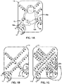
- FIG. 1A illustrates (a top-view of) measuring system 10 for non-invasive determination of one or more vital sign states of subject 12.
- Measuring system 10 may interchangeably be referred to as system 10.
- Measuring system 10 may include one or more of a body of engagement 14, multiple coupling sensors 16, multiple vital sign sensors 18, and/or other components (including components illustrated in other figures as being included in measuring system 10).
- measuring system 10 may include one or more of a body of engagement 14, multiple coupling sensors 16, multiple temperature sensors 18, one or more zero-heat-flux temperature sensors 20, and/or other components (including components illustrated in other figures as being included in measuring system 10).
- Body of engagement 14 may interchangeably be referred to as "structure of engagement,” “structure,” “support-structure of engagement,” or “support-structure.”
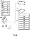
- FIG. 2 schematically illustrates measuring system 10, which may further include one or more vital sign state adjustment elements 32 (for example, in the case of thermal adjustment elements, vital sign state adjustment elements may include one or more heating elements 34 and/or one or more cooling elements 36), one or more processors 110, an electronic storage 130, a user interface 120, and/or other components and/or computer program modules.
- the computer program modules may include one or more of a coupling module 111, a vital sign state determination module 112, a quality control module 113, a tracking module 114, a map module 115, a target module 116, a control module 117, and/or other modules.
- a user 108 of measurement system 10 such as, by way of non-limiting example, a care-giver, a therapy-decision-maker, and/or a medical professional.
- Non-invasive determination of one or more vital sign states of a subject may contribute to improved medical care and/or maintenance of recommended vital sign state parameters.
- non-invasive determination of one or more temperatures of a neonatal subject and/or infant may contribute to thermal protection and/or maintenance of recommended temperatures.
- Measuring temperatures of a subject may be important in many clinical situations, including but not limited to neonates in a neonatal intensive care unit (NICU).
- the multiple temperatures may include peripheral temperatures at various locations, core temperatures at or near different parts of the body, and/or other temperatures.
- peripheral temperatures may include skin temperatures of hands, feet, and/or other body parts.
- core temperatures may include (estimated, determined, measured, and/or otherwise approximated) temperatures of various organs and/or body parts, including but not limited to the brain, the heart, the abdomen, the chest, and/or other organs and/or body parts.
- non-invasive may refer to the absence of adhesives to keep sensors in place and/or the absence of physical equipment penetrating or adhering to the skin or being inserted in any manner into the subject.
- Adhesive (vital sign state) sensors may damage the skin and cause stress and/or pain when used.
- Information regarding on or more vital sign states of a subject may be medically and/or diagnostically relevant.
- thermoregulation, circulatory function, perfusion, infections, oxygen saturation, and/or other conditions of a subject may be diagnosed, monitored, treated, and/or otherwise benefit by virtue of having more and/or more accurate information regarding one or more temperatures, and/or other vital sign state information of the subject.
- Medical conditions and/or issues mentioned in this disclosure are intended to be exemplary and without limitation.
- body of engagement 14 is configured to engage with a subject 12, e.g. a neonate and/or infant.
- body of engagement 14 may be implemented as a (subject) support structure configured to support subject 12 thereon.
- a subject support structure may be a mattress, a bed, a pad, a blanket, a wrap, a pillow, an incubator, and/or other structure suitable to engage and/or support a subject 12, e.g. a neonate and/or infant.
- body of engagement 14 may be an article of clothing configured to be worn by and/or wrapped around subject 12.
- Body of engagement 14 may be configured to carry one or more sensors, e.g. one or more temperature sensors 16. As depicted in FIG. 1A , body of engagement 14 may be wrapped around subject 12 such that multiple coupling sensors 16 and multiple temperature sensors 18 engage, touch, and/or (electrically and/or thermally) couple with subject 12.
- FIG. 1A depicts multiple coupling sensors 16 as well as specific coupling sensors referred to as coupling sensor 16a, coupling sensor 16b, and coupling sensor 16c, and multiple zero-heat-flux temperature sensors 20 as well as a specific zero-heat-flux temperature sensor 20a.
- Other temperature sensors, coupling sensors and zero-heat-flux temperature sensors are depicted in FIG.
- the term “measure” refers to any combination of measuring, estimating, and/or approximating based on output generated by one or more sensors.
- the term “measurement” refers to any combination of one or more measurements, estimations, and/or approximations based on output generated by one or more sensors.
- Zero-heat-flux temperature sensor(s) 20 operate according to the thermal principle known as the zero-heat flux principle, which may be described, e.g ., in one or more related applications incorporated by reference into the present application.
- temperature sensor(s) 18 may be used to determine one or more peripheral temperatures of subject 12.
- zero-heat-flux temperature sensor(s) 20 may be used to determine one or more core temperatures of subject 12.
- one or more temperature sensors 18 may be configured to determine an ambient temperature around and/or near subject 12.
- Coupling sensors 16 may be configured to generate signals (interchangeably referred to herein as output signals or coupling signals) conveying coupling information between two objects ( e.g . the coupling sensor itself and subject 12). Coupling sensors 16 may be configured to generate signals conveying electrical, thermal, magnetic, pressure, and/or other coupling information. Coupling sensor(s) 16 may be supported and/or carried by body of engagement 14. In some embodiments, coupling sensor(s) may include one or more magnetic field sensors, one or more pressure sensors and/or one or more capacitive sensors. Signals and/or information conveyed by coupling sensor(s) 16 may be referred to as coupling information.
- One or more coupling sensors 16 may be associated with one or more temperature sensors, including but not limited using a 1-to-1 association (e.g. for co-located sensor pairs of a temperature sensor and a coupling sensor).
- coupling sensors 16a, 16b, and 16c may be associated with different (zero-heat-flux) temperature sensors.
- coupling information may be conveyed by the intensity, strength, magnitude, and/or level of the signal generated by coupling sensor(s) 16.
- an individual coupling sensor 16 may emit a signal (e.g.
- an individual coupling sensor may be associated with multiple temperature sensors. In some embodiments, multiple coupling sensors may be associated with an individual temperature sensor. In some embodiments, association between one or more coupling sensors 16 and one or more temperature sensors 18 may be based on proximity (including but not limited to a weighted association of the information from a temperature sensor based on coupling information from the nearest multiple coupling sensors). In some embodiments, an individual temperature sensor and an individual coupling sensor may be integrated, embedded, and/or otherwise combined into a single unit, component, and/or device capable of the joint features and functionality attributed herein to an individual temperature sensor and an individual coupling sensor.
- coupling sensor 16 depicted in FIG. 1A may be associated with temperature sensor 18a.
- coupling information from coupling sensor 16a may be used to qualify information from temperature sensor 18a.
- Information from temperature sensor 18a may be deemed useful and/or reliable based on the information from coupling sensor 16a.
- information from temperature sensor 18a may be discarded based on poor and/or weak coupling between coupling sensor 16a and subject 12, as may be conveyed through coupling information from coupling sensor 16a.
- the relative position of coupling sensor 16a in relation to temperature sensor 18a as depicted in FIG. 1A is merely exemplary and not intended to be limiting in any way.
- FIG. 1B depicts the same body of engagement 14 (and the same measuring system 10) as depicted in FIG. 1A without subject 12 obscuring the view.
- Body of engagement 14 may include multiple temperature sensors 18 and multiple coupling sensors 16.
- the sensors depicted in FIG. 1B may be arranged to form a set, pattern, matrix, grid, and/or other predetermined shape. As depicted in FIG. 1 , the sensors of measuring system 10 may be arranged in multiple diagonal lines.
- the temperature matrix 38 may be arranged in electrical connection with processor 110 facilitated by wires 44. Such electrical connections may also be effectuated by way of wireless electronic communication between the coupling sensors 16 and/or temperature sensors 18 of the temperature matrix 48 and processor 110. Each coupling sensor 16 and/or temperature sensor 18 may communicate with processor 110 individually or temperature matric 38 may communicate with the processor 110, aggregating data from the sensors. Wireless communication may be achieved using one or more additional components.
- FIG. 3B illustrates a body of engagement 14 configured to engage with and/or support a subject 12.
- FIG. 3B specifically illustrates a carrier, or nest, for a neonate configured to maintain appropriate positioning and flexion of a neonate.
- the temperature matrix 38 may be integrated into the body of engagement 14, such that the temperature matrix 38 is positioned below the fabric in direct connection with the subject 12 to provide non-invasive temperature measurements.
- measuring system 10 may include electronic storage 130 comprising electronic storage media that electronically stores information.
- the electronic storage media of electronic storage 130 includes one or both of system storage that is provided integrally ( i.e., substantially non-removable) with measuring system 10 and/or removable storage that is connectable to measuring system 10 via, for example, a port ( e.g ., a USB port, a FireWire port, etc .) or a drive ( e.g ., a disk drive, etc .).
- a port e.g ., a USB port, a FireWire port, etc .
- a drive e.g ., a disk drive, etc .
- Electronic storage 130 may be a separate component within measuring system 10, or electronic storage 130 may be provided integrally with one or more other components of system 10 (e.g ., processor 110).
- processor 110 is configured to provide information processing capabilities in measuring system 10.
- processor 110 includes one or more of a digital processor, an analog processor, a digital circuit designed to process information, an analog circuit designed to process information, and/or other mechanisms for electronically processing information.
- processor 110 is shown in FIG. 2 as a single entity, this is for illustrative purposes only. In some embodiments, processor 110 includes a plurality of processing units.
- processor 110 is configured to execute one or more computer program modules.
- the one or more computer program modules include one or more of a coupling module 111, a vital sign state determination module 112, a quality control module 113, a tracking module 114, a map module 115, a target module 116, a control module 117, and/or other modules.
- Processor 110 may be configured to execute modules 111-117 by software; hardware; firmware; some combination of software, hardware, and/or firmware; and/or other mechanisms for configuring processing capabilities on processor 110.
- modules 111-117 are illustrated in FIG. 2 as being co-located within a single processing unit, in implementations in which processor 110 includes multiple processing units, one or more of modules 111-117 may be located remotely from the other modules.
- the description of the functionality provided by the different modules 111-117 described below is for illustrative purposes, and is not intended to be limiting, as any of modules 111-117 may provide more or less functionality than is described.
- processor 110 may be configured to execute one or more additional modules that may perform some or all of the functionality attributed below to one of modules 111-117.
- Sensors in this disclosure may be configured to generate output signals in an ongoing manner, e.g. throughout the day. This may include generating signals intermittently, periodically ( e.g. at a sampling rate), continuously, continually, at varying intervals, and/or in other ways that are ongoing during at least a portion of period of a day, week, month, or other duration.
- the sampling rate may be about 0.001 second, 0.01 second, 0.1 second, 1 second, about 10 seconds, about 1 minute, and/or other sampling rates. It is noted that multiple individual sensors may operate using different sampling rates, as appropriate for the particular output signals and/or (frequencies related to particular) parameters derived therefrom.
- Coupling module 111 of measuring system 10 in FIG. 2 is configured to determine coupling levels for one or more sensors of measuring system 10, including but not limited to one or more coupling sensors 16, one or more temperature sensors 18, one or more zero-heat-flux temperature sensors 20, and/or other sensors.
- the term "coupling level” may refer to coupling strength (e.g. of electrical signals), and/or signal strength ( e.g. of electrical signals).
- coupling levels may be based on pressure levels, capacitive levels, and/or other types of levels and/or combinations thereof that may indicate whether (and/or to what extent) the output signal from a sensor should be deemed reliable.
- a coupling level may indicate whether the output signal from a sensor should be discarded, e.g. in favor of stronger and/or more reliable signals from other sensors.
- coupling module 111 may be configured to determine individual coupling levels for individual temperature sensors 18. In some embodiments, determinations by coupling module 111 may be based on one or more coupling signals generated by coupling sensors 16. For example, a coupling level for temperature sensor 18a may be based on coupling information from coupling sensor 16a. In some embodiments, individual temperature sensors 18 may be associated with individual coupling sensors 16, and/or vice versa. In some embodiments, information from an individual temperature sensor 18 may be weighted according to the coupling levels of multiple nearby coupling sensors 116. The coupling level for an individual temperature sensor 18 may change over time, for example between measurements taken of individual coupling sensors 116. Changes in coupling levels over time may, for example, be caused by movement of subject 12.
- Coupling levels from coupling sensors 16 may be ordered, ranked, and/or otherwise compared to coupling levels from one or more other coupling sensors. For example, coupling levels from coupling sensors 116 within a predetermined distance of each other and/or another sensor may be compared with each other and/or with one or more thresholds. Coupling levels from coupling sensors 16 may be compared based on the output signals being generated within the same period, duration, and/or window. By way of non-limiting example, in some embodiments coupling sensors 16 may be configured to generate output signals at a sampling rate of 1 second per measurement.
- Coupling module 111 may be configured to determine coupling levels for some or all coupling sensors 16 at the same or similar sampling rate such that changing coupling levels may be reevaluated at the same or similar sampling rate to determine whether to use or discard corresponding temperature measurements from associated temperature sensors 18.
- Vital sign state determination module 112 of measuring system 10 in FIG. 2 is configured to determine one or more vital sign states of subject 12. As illustrated in the figures, and by way of example only, vital sign state determination module 112 may be configured to determine one or more temperatures of subject 12. The temperatures may include one or more peripheral temperatures at various locations, one or more core temperatures at or near different parts of the body, and/or other temperatures. In some embodiments, vital sign state determination module 112 may be configured to determine multiple temperatures and/or multiple types of temperatures of subject 12, including but not limited to one or more peripheral temperatures and/or one or more core temperatures.
- the coupling reliability index determined by quality control module 113 may be further configured to account for the weight of subject 12 without necessitating recalibration of measuring system 10. Coupling levels determined by coupling module 111 may be higher for a subject that is heavier compared to a subject that is lighter.
- coupling reliability index module 113 may be configured to determine the most likely temperature of subject 12 based upon the determined coupling reliability indexes determined for the multiple temperature sensors 18.
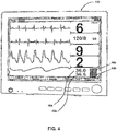
- FIG. 4 illustrates an example of user interface 120 for use with measuring system 10 for non-invasive vital sign state measurements of subject 12.
- the user interface 120 may be configured to facilitate display of one or more temperature measurements 46a, 46b of the subject 12.
- User interface 120 may also be configured to facilitate display of other vital sign states, such as heart rate, blood pressure and/or other vital sign states of subject 12.
- User interface 120 may be further configured to display an indication of one or more reliability indexes 48a, 48b as determined by quality control module 113.
- Such reliability indexes may relate to any and/or all of the vital sign states displayed on user interface 120.
- temperature measurement 46a may be the temperature of subject 12 measured at a first set of one or more temperature sensors 18 at a first location of the subject 12.
- Temperature measurement 46b may be the temperature of a subject 12 measured at a second set of one or more temperature sensors 18 at a second location of the subject 12.
- Indication of reliability index 48a provides an indication of the reliability of temperature measurement 46a based upon coupling level(s) for the first set of temperature sensors 18 at a first location of the subject 12.
- Indication of reliability index 48b provides an indication of the reliability of temperature measurement 46b based upon coupling level(s) for the second set of temperature sensors 18 at a second location of the subject 12.
- the indicia of reliability index 48a may be a color indicating that the temperature measurement 46a is reliable, due to the relatively high coupling levels at the first location compared to the coupling levels at the second location which causes the indicia of reliability index 48b to be a color indicating that the temperature measurement 46b is less reliable.
- measuring system 10 in FIG. 2 may comprise a tracking module 114 configured to track changed in the coupling reliability index of individual vital state sensors over time.
- Tracking module 114 may be configured to track changes in the span of about 10 minutes, about an hour, about 2 hours, about 4 hours, about 8 hours, about 12 hours, about 24 hours, about 48 hours, about 72 hours, about a week, about a month, about 2 months, and/or other amounts of time.
- Relatively slow changes in coupling reliability index (compared to the sampling rate) may indicate a change in position of the subject 12, or a change in the functionality of one or more of the coupling sensors 16 and/or temperature sensors 18 indicating that the coupling sensors 16 and/or temperature sensors 18 have a fault.
- temperature sensors 16 may include one or more zero-heat-flux temperature sensors 20.
- Vital sign state determination module 112 may be configured to determine one or more core temperatures of subject 12 based on output signals generated by zero-heat-flux temperature sensors 20. Alternatively, and/or simultaneously, one or more determined core temperatures of subject 12 may further be based on one or more coupling levels determined by coupling module 111. For example, a particular core temperature may be based on a coupling level for zero-heat-flux temperature sensor 20a, which may be based on coupling information from coupling sensor 116b. Vital sign state determination module 112 may be configured to determine multiple temperatures of subject 12 over time. By way of non-limiting example, FIG.
- vital sign state determination module 112 may be configured to determine one or more temperatures of subject 12 without using or needing coupling information. For example, determinations by vital sign state determination module 112 may be based on one or more of positional information (described elsewhere herein), and/or a temperature map of subject 12 ( e.g. determined by map module 115).
- Map module 115 of measuring system 10 in FIG. 2 is configured to determine and/or construct a vital sign state profile of subject 12 based on vital sign states determined by vital sign state determination module 112 of subject 12.
- a vital sign state profile of subject 12 may include a temperature map of subject 12 based on temperatures determined by vital sign state determination module 112 and/or positional information of subject 12.
- the term "temperature map” may be used interchangeably with the terms "temperature profile” and "graphical temperature representation”.
- a temperature map may depict an image subject 12 combined with information about different relevant temperatures.
- FIG. 6A illustrates a temperature map 62 of subject 12.
- the image used in temperature map 62 may be an actual representation (e.g.
- Temperature map 62 may, by way of non-limiting example, include the same or similar temperatures as depicted in FIG. 5 , including temperatures for the brain, chest, abdomen, hands, feet, and ambient temperature.
- the end temperatures i.e. the right-most temperatures depicted from graph 49 ( FIG. 5 ) are depicted as the current temperatures in temperature map 62 in FIG. 6A .
- Temperature map 62 may be 2-dimensional or more-then-2-dimensional, for example 3-dimensional.
- a temperature map of subject 12 may be based on a (parameterized) model using multiple determined temperatures of subject 12.
- the model may use coupling information.
- the model may include coupling reliability index information tracked over time by tracking module 114 to determine the position of subject 12.
- the model may facilitate display of a temperature map of subject 12 on user interface 120 of FIG. 4 .
- the model may use positional information of subject 12, e.g. for embodiments in which positional information is determined independently of a temperature map.
- a temperature map may be inferred from multiple determined temperatures of subject 12 and positional information of subject 12.
- a temperature map may depict regions of subject 12 having the same or similar temperature, such as a heat map. Such regions may for example be indicated using different colors.
- the image used in temperature map 64 may be an actual representation (e.g. a photograph) of subject 12, or a schematic representation (including head, torso, arms, and legs) as depicted in FIG. 6B . This list of body parts is exemplary and not intended to be limiting in any way.
- FIG. 6B illustrates a temperature map 64 that depicts regions of subject 12 having similar temperatures.
- two regions are indicated as having a temperature between 37.3 °C and 37.4 °C, three regions are indicated as having a temperature between 37.1 °C and 37.3 °C, one region is indicated as having a temperature between 36.9 °C and 37.1 °C.
- the different temperatures may be indicated in a temperature map using different colors.
- the image used in temperature map 64 to represent subject 12 may be a real-time 3-dimensional representation of subject 12.
- one or both of the two described regions may be core temperatures and one or more of the temperatures and/or regions associated with the extremities of subject 12 may be peripheral temperatures.
- the measurement of multiple vital sign states may produce a vital sign state profile of subject 12.
- the description herein with reference to the measurement of temperatures of subject 12 can be applied to the measurement of any vital sign of subject 12 and also to multiple vital sign states of subject 12 at the same time to provide a holistic view of the vital signs of subject 12.
- Tracking module 114 of system 10 in FIG. 2 may be further configured to track changes in one or more temperatures over time.
- Tracking module 114 may be configured to track changes in the span of about 10 minutes, about an hour, about 2 hours, about 4 hours, about 8 hours, about 12 hours, about 24 hours, about 48 hours, about 72 hours, about a week, about a month, about 2 months, and/or other amounts of time.
- Relatively slow changes in temperature may indicate a change in a medical condition that might be noteworthy. For example, a particular temperature (e.g. determined by vital sign state determination module 112) may rise or fall outside an acceptable and/or preferred range for such a temperature.
- tracking module 114 may be configured to determine whether one or more temperatures and/or changes in temperatures indicate significant information pertinent to diagnostic purposes, as described elsewhere herein.
- System 10 may be configured to measure other patient-specific parameters as needed to support the process of such determinations, including but not limited to physiological parameters, respiratory parameters, and/or any other medically relevant parameters and/or combinations thereof.
- a particular predetermined combination of a change in heart rate, a change in respiratory rate, and a change in one or more temperatures may indicate a particular medical condition or emergency that may be noteworthy to a user and/or caregiver.
- the term "predetermined” may refer to a determination that has been made prior to usage of system 10 on a particular subject.
- a programmed relation, value, or threshold may be referred to as predetermined.
- tracking module 114 may be configured to notify and/or alert a user or caregiver responsive to one or more determinations (described in this disclosure) having been made.
- Control module 117 of measuring system 10 in FIG. 2 is configured to control one or more thermal adjustment elements 32.
- control module 117 may be configured to control one or more thermal adjustment elements 32 in accordance with a therapy regimen.
- control module 116 may be configured to control one or more thermal adjustment elements 32 to adjust one or more of the determined temperatures (e.g. as determined by vital sign state determination module 112).
- control module 117 may be configured to control one or more thermal adjustment elements 32 based on one or more comparisons between a determined temperature and a target temperature (and/or target temperature range).
- control module 117 may be configured to control one or more thermal adjustment elements 32 in accordance with one or more determined target temperatures and/or target temperature ranges (e.g.
- control module 117 may be configured to increase or decrease a particular body part, organ, area, and/or region of subject 12. This may be referred to as heating or cooling, respectively.
- heating may be accomplished using one or more heating elements 34; cooling may be accomplished using one or more cooling elements 36.
- Selection of one or more particular thermal adjustment elements 32 may depend on locality and/or proximity of the corresponding temperature sensor(s) 18.
- selection of one or more particular thermal adjustment elements 32 may depend on coupling levels as determined for nearby coupling sensors 11641, by virtue of the notion that weak electrical and/or thermal coupling may affect the efficacy of a thermal adjustment element at the same or similar location ( e.g. for a thermal adjustment element 32 located close to a coupling sensor 16).
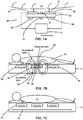
- a first temperature sensor 70 may be positioned on a first side of thermo-isolator 68, and a second temperature sensor 70 may be positioned on a second side of thermo-isolator 68.
- Heating elements 66 may be positioned on the first side and/or second side of thermo-isolator 68. Heating element 66 may be a resistor and/or other heating element.
- coupling sensors 16 of FIGs. 1A-1B-1C may be electrodes 22 adapted to form the capacitive coupling with subject 12.
- the thermo-isolator 68 may have a uniform temperature grade across it, and may be configured to be a thermal equalizer for the zero-heat-flux temperature sensor 20.
- heating elements 66 may also be electrodes 22 to form the capacitive coupling with subject 12, obviating the need for additional separate electrodes 22.
- zero-heat-flux temperature sensor 20 may be combined with other zero-heat-flux temperature sensor to form a matrix, such as thermal matrix 40 illustrated in FIG. 3A .
- electrodes 22, also being heating elements 66 may be floating electrodes in order to homogenously distribute the heat across the thermal matrix 40.
- Electrodes 22, being capacitive sensors 16 of FIG. 2 may also be adapted to detect biological electric fields such as those produced by heart activity, lung activity, or other organ activity. In this manner, electrodes 22 may also be used to measure ECG, heart rate, respiration, and/or other biological processes in subject 12. Electrodes 22, also functioning as capacitive sensors 16 will generate signals conveying coupling information for those biological electric fields.
- the coupling sensors 16 comprise of a first set of one or more excitation coils 24 configured to generate a first set of one or more magnetic fields 26 and to detect a second set of one or more magnetic fields 30 generated by subject 12, from eddy currents generated by subject 12, in response to the generation of first set of one or more magnetic fields 26.
- a second set of one or more excitation coils 28 configured to detect second set of one or more magnetic fields 30, instead of first set of one or more excitation coils 26 both generating and detecting magnetic fields.
- Heater element 66 may be an excitation coil. In this manner heater element 66 may also be first set of one or more excitation coils 26.
- quality control module 113 is configured to determine the coupling reliability index based on the capacitance formed between first set of one or more excitation coils 24 and subject 12.
- pressure foil 76 may be positioned within body of engagement 14 on the opposing side of the one or more zero-heat-flux temperature sensors 20 to subject 12.
- pressure foil 76 may be a set of one or more pressure foils integrated with each of the one or more zero-heat-flux-sensors 20.
- pressure foil 76 is configured to generate signals conveying pressure information
- coupling module 111 is configured to determine coupling levels for individual ones of the temperature sensors based on the pressure information conveyed in the signals generated by pressure foil 76.
- Quality control module 113 is configured to determine a relatively high coupling reliability index for the temperature sensor 18 located at a high-pressure region on pressure foil 76, compared to other temperature sensors at low-pressure regions on pressure foil 76.
- FIG. 8 illustrates a specific method 800 to determine one or more temperatures of a subject.
- method 800 is an exemplary embodiment of the disclosed non-invasive method for determining one or more vital sign states of a subject and is not intended to be limiting.
- the operations of method 800 presented below are intended to be illustrative. In certain embodiments, method 800 may be accomplished with one or more additional operations not described, and/or without one or more of the operations discussed. Additionally, the order in which the operations of method 800 are illustrated in FIG. 8 and described below is not intended to be limiting.
- method 800 may be implemented in one or more processing devices (e.g ., a digital processor, an analog processor, a digital circuit designed to process information, an analog circuit designed to process information, and/or other mechanisms for electronically processing information).
- the one or more processing devices may include one or more devices executing some or all of the operations of method 800 in response to instructions stored electronically on an electronic storage medium.
- the one or more processing devices may include one or more devices configured through hardware, firmware, and/or software to be specifically designed for execution of one or more of the operations of method 800.
- coupling signals are generated conveying coupling information with the subject at or near a point of engagement between the subject and the body of engagement.
- operation 804 is performed by coupling sensors the same as or similar to coupling sensors 16 (shown in FIG. 1A and described herein).
- output signals are generated conveying temperatures of the subject at or near a point of engagement between the subject and the body of engagement.
- operation 806 is performed by temperature sensors the same as or similar to temperature sensors 18 (shown in FIG. 1A and described herein).
Landscapes
- Health & Medical Sciences (AREA)
- Life Sciences & Earth Sciences (AREA)
- Engineering & Computer Science (AREA)
- Physics & Mathematics (AREA)
- Animal Behavior & Ethology (AREA)
- Public Health (AREA)
- General Health & Medical Sciences (AREA)
- Surgery (AREA)
- Veterinary Medicine (AREA)
- Biophysics (AREA)
- Pathology (AREA)
- Biomedical Technology (AREA)
- Heart & Thoracic Surgery (AREA)
- Medical Informatics (AREA)
- Molecular Biology (AREA)
- Physiology (AREA)
- Cardiology (AREA)
- General Physics & Mathematics (AREA)
- Computer Networks & Wireless Communication (AREA)
- Nuclear Medicine, Radiotherapy & Molecular Imaging (AREA)
- Radiology & Medical Imaging (AREA)
- Signal Processing (AREA)
- Psychiatry (AREA)
- Computer Vision & Pattern Recognition (AREA)
- Artificial Intelligence (AREA)
- Vascular Medicine (AREA)
- Pulmonology (AREA)
- Measuring And Recording Apparatus For Diagnosis (AREA)
- Measurement Of The Respiration, Hearing Ability, Form, And Blood Characteristics Of Living Organisms (AREA)
Applications Claiming Priority (2)
| Application Number | Priority Date | Filing Date | Title |
|---|---|---|---|
| US201361917634P | 2013-12-18 | 2013-12-18 | |
| PCT/IB2014/066688 WO2015092607A1 (en) | 2013-12-18 | 2014-12-08 | Vital sign monitoring and control |
Publications (2)
| Publication Number | Publication Date |
|---|---|
| EP3082578A1 EP3082578A1 (en) | 2016-10-26 |
| EP3082578B1 true EP3082578B1 (en) | 2019-07-10 |
Family
ID=52434878
Family Applications (1)
| Application Number | Title | Priority Date | Filing Date |
|---|---|---|---|
| EP14833193.7A Active EP3082578B1 (en) | 2013-12-18 | 2014-12-08 | Vital sign monitoring and control |
Country Status (5)
| Country | Link |
|---|---|
| US (1) | US20170000347A1 (ja) |
| EP (1) | EP3082578B1 (ja) |
| JP (1) | JP6720078B2 (ja) |
| CN (1) | CN105992551B (ja) |
| WO (1) | WO2015092607A1 (ja) |
Families Citing this family (23)
| Publication number | Priority date | Publication date | Assignee | Title |
|---|---|---|---|---|
| US20170112387A1 (en) * | 2015-10-26 | 2017-04-27 | Shreya Venkatesh | Body temperature detection and control |
| JP7159047B2 (ja) * | 2015-12-23 | 2022-10-24 | コーニンクレッカ フィリップス エヌ ヴェ | 人のバイタルサインを決定する装置、システム及び方法 |
| JP6735129B2 (ja) * | 2016-03-30 | 2020-08-05 | 株式会社キーエンス | 変位計の測定結果を表示するプログラム、変位計システムおよび変位測定方法 |
| USD815132S1 (en) * | 2016-05-30 | 2018-04-10 | Drägerwrk Ag & Co. Kgaa | Display screen or portion thereof with graphical user interface |
| USD815655S1 (en) * | 2016-05-30 | 2018-04-17 | Drägerwerk AG & Co. KGaA | Display screen or portion thereof with graphical user interface |
| USD815654S1 (en) * | 2016-05-30 | 2018-04-17 | Drägerwerk AG & Co., KGaA | Display screen or portion thereof with graphical user interface |
| USD813895S1 (en) * | 2016-05-30 | 2018-03-27 | Drägerwerk AG & Co. KGaA | Display screen or portion thereof with graphical user interface |
| USD813896S1 (en) * | 2016-05-30 | 2018-03-27 | Drägerwerk AG & Co. KGaA | Display screen or portion thereof with graphical user interface |
| USD812638S1 (en) * | 2016-05-30 | 2018-03-13 | Drägerwerk AG & Co. KGaA | Display screen or portion thereof with graphical user interface |
| USD815133S1 (en) * | 2016-05-30 | 2018-04-10 | Drägerwerk AG & Co. KGaA | Display screen or portion thereof with graphical user interface |
| USD833467S1 (en) * | 2016-05-30 | 2018-11-13 | Drägerwerk AG & Co. KGaAa | Display screen or portion thereof with graphical user interface |
| USD812088S1 (en) * | 2016-05-30 | 2018-03-06 | Drägerwerk AG & Co. KGaA | Display screen or portion thereof with graphical user interface |
| USD814500S1 (en) * | 2016-05-30 | 2018-04-03 | Drägerwerk AG & Co. KGaA | Display screen or portion thereof with graphical user interface |
| US20170347960A1 (en) * | 2016-06-06 | 2017-12-07 | General Electric Company | Mobile newborn care bed and methods of newborn care |
| CN110402100A (zh) | 2017-03-14 | 2019-11-01 | M·哈伯 | 用于无创核心体温监测的方法、系统和装置 |
| US10555679B2 (en) * | 2017-06-20 | 2020-02-11 | General Electric Company | Non-contact heart rate monitoring |
| US20200288983A1 (en) * | 2019-02-26 | 2020-09-17 | Masimo Corporation | Respiratory core body temperature measurement systems and methods |
| US11166677B2 (en) * | 2019-03-06 | 2021-11-09 | General Electric Company | Systems and methods for monitoring a patient |
| CN109820484A (zh) * | 2019-03-14 | 2019-05-31 | 深圳市弘楚源科技发展有限公司 | 一种带有传感装置监测睡眠呼吸障碍的床垫 |
| CN110338765B (zh) * | 2019-07-18 | 2020-10-20 | 中原工学院 | 基于lightGBM和蜂群算法的儿童睡眠监测系统及监测方法 |
| US20210307616A1 (en) * | 2020-04-01 | 2021-10-07 | Marshall STEWMAN | Fever Detector |
| US11771406B2 (en) * | 2020-08-12 | 2023-10-03 | Apple Inc. | In-bed temperature array for menstrual cycle tracking |
| WO2023076462A1 (en) * | 2021-10-27 | 2023-05-04 | Monovo, LLC | Using multiple devices to monitor physiological data |
Family Cites Families (13)
| Publication number | Priority date | Publication date | Assignee | Title |
|---|---|---|---|---|
| US6381482B1 (en) * | 1998-05-13 | 2002-04-30 | Georgia Tech Research Corp. | Fabric or garment with integrated flexible information infrastructure |
| US6755795B2 (en) * | 2001-10-26 | 2004-06-29 | Koninklijke Philips Electronics N.V. | Selectively applied wearable medical sensors |
| AT410844B (de) * | 2002-03-25 | 2003-08-25 | Christian Stockinger | Messvorrichtung und methode zur ermittlung von ungenauem anlegen von sensoren und reduzierung von messfehlern für robuste messsysteme für z.b. physiologische messgrössen |
| DE102005048496A1 (de) * | 2005-10-07 | 2007-04-12 | Inmeditec Medizintechnik Gmbh | Messmatte |
| JP4848732B2 (ja) * | 2005-10-17 | 2011-12-28 | 株式会社日立製作所 | 端末装置 |
| US8406866B2 (en) * | 2005-12-06 | 2013-03-26 | St. Jude Medical, Atrial Fibrillation Division, Inc. | System and method for assessing coupling between an electrode and tissue |
| US20100100004A1 (en) * | 2008-10-16 | 2010-04-22 | Koninklijke Nederlandse Akademie Van Wetenschappen | Skin Temperature Measurement in Monitoring and Control of Sleep and Alertness |
| CN102355847B (zh) * | 2009-01-24 | 2016-05-25 | 杨章民 | 感测装置 |
| CN102348967B (zh) * | 2009-03-13 | 2014-06-04 | 皇家飞利浦电子股份有限公司 | 零热通温度感测装置 |
| JP5526230B2 (ja) * | 2009-07-14 | 2014-06-18 | コーニンクレッカ フィリップス エヌ ヴェ | 接触検出装置及びその動作方法 |
| JP5864884B2 (ja) * | 2011-04-12 | 2016-02-17 | 株式会社ティアンドデイ | 測定装置および測定方法 |
| WO2012172501A1 (en) * | 2011-06-15 | 2012-12-20 | Koninklijke Philips Electronics N.V. | Peripheral temperature measuring |
| US9265427B2 (en) * | 2012-03-19 | 2016-02-23 | Welch Allyn, Inc. | Systems and methods for determining patient temperature |
-
2014
- 2014-12-08 EP EP14833193.7A patent/EP3082578B1/en active Active
- 2014-12-08 CN CN201480075538.7A patent/CN105992551B/zh active Active
- 2014-12-08 US US15/104,801 patent/US20170000347A1/en not_active Abandoned
- 2014-12-08 WO PCT/IB2014/066688 patent/WO2015092607A1/en active Application Filing
- 2014-12-08 JP JP2016539942A patent/JP6720078B2/ja active Active
Non-Patent Citations (1)
| Title |
|---|
| None * |
Also Published As
| Publication number | Publication date |
|---|---|
| CN105992551A (zh) | 2016-10-05 |
| WO2015092607A1 (en) | 2015-06-25 |
| JP6720078B2 (ja) | 2020-07-08 |
| JP2017501793A (ja) | 2017-01-19 |
| CN105992551B (zh) | 2019-12-03 |
| EP3082578A1 (en) | 2016-10-26 |
| US20170000347A1 (en) | 2017-01-05 |
Similar Documents
| Publication | Publication Date | Title |
|---|---|---|
| EP3082578B1 (en) | Vital sign monitoring and control | |
| CN105960194B (zh) | 热监测和控制 | |
| JP7303854B2 (ja) | 評価装置 | |
| US20210393155A1 (en) | Apparatus and method for measuring physiological parameters of mammal subject and applications of same | |
| US10064566B2 (en) | Electrocardiography monitoring system and method | |
| US10820859B2 (en) | Systems and methods for detecting pulse wave velocity | |
| US10603509B2 (en) | Phototherapy blanket temperature determination | |
| JP6134707B2 (ja) | 末梢体温の測定 | |
| CN106999055A (zh) | 用于确定针对睡眠阶段分类的谱边界的系统和方法 | |
| RU2742707C1 (ru) | Бесконтактный мониторинг частоты сердечных сокращений | |
| WO2017038966A1 (ja) | 生体情報出力装置、生体情報出力方法及びプログラム | |
| WO2014088886A1 (en) | Csf shunt flow evaluation apparatus and method using a conformable expanded dynamic range thermosensor | |
| Bestbier | Development of a vital signs monitoring wireless ear probe | |
| WO2022221848A1 (en) | Systems and methods for multivariate stroke detection |
Legal Events
| Date | Code | Title | Description |
|---|---|---|---|
| PUAI | Public reference made under article 153(3) epc to a published international application that has entered the european phase |
Free format text: ORIGINAL CODE: 0009012 |
|
| 17P | Request for examination filed |
Effective date: 20160718 |
|
| AK | Designated contracting states |
Kind code of ref document: A1 Designated state(s): AL AT BE BG CH CY CZ DE DK EE ES FI FR GB GR HR HU IE IS IT LI LT LU LV MC MK MT NL NO PL PT RO RS SE SI SK SM TR |
|
| AX | Request for extension of the european patent |
Extension state: BA ME |
|
| DAX | Request for extension of the european patent (deleted) | ||
| GRAP | Despatch of communication of intention to grant a patent |
Free format text: ORIGINAL CODE: EPIDOSNIGR1 |
|
| STAA | Information on the status of an ep patent application or granted ep patent |
Free format text: STATUS: GRANT OF PATENT IS INTENDED |
|
| INTG | Intention to grant announced |
Effective date: 20190201 |
|
| GRAS | Grant fee paid |
Free format text: ORIGINAL CODE: EPIDOSNIGR3 |
|
| GRAA | (expected) grant |
Free format text: ORIGINAL CODE: 0009210 |
|
| STAA | Information on the status of an ep patent application or granted ep patent |
Free format text: STATUS: THE PATENT HAS BEEN GRANTED |
|
| AK | Designated contracting states |
Kind code of ref document: B1 Designated state(s): AL AT BE BG CH CY CZ DE DK EE ES FI FR GB GR HR HU IE IS IT LI LT LU LV MC MK MT NL NO PL PT RO RS SE SI SK SM TR |
|
| REG | Reference to a national code |
Ref country code: GB Ref legal event code: FG4D |
|
| REG | Reference to a national code |
Ref country code: CH Ref legal event code: EP Ref country code: AT Ref legal event code: REF Ref document number: 1152683 Country of ref document: AT Kind code of ref document: T Effective date: 20190715 |
|
| REG | Reference to a national code |
Ref country code: DE Ref legal event code: R096 Ref document number: 602014049941 Country of ref document: DE |
|
| REG | Reference to a national code |
Ref country code: IE Ref legal event code: FG4D |
|
| REG | Reference to a national code |
Ref country code: NL Ref legal event code: MP Effective date: 20190710 |
|
| REG | Reference to a national code |
Ref country code: LT Ref legal event code: MG4D |
|
| REG | Reference to a national code |
Ref country code: AT Ref legal event code: MK05 Ref document number: 1152683 Country of ref document: AT Kind code of ref document: T Effective date: 20190710 |
|
| PG25 | Lapsed in a contracting state [announced via postgrant information from national office to epo] |
Ref country code: LT Free format text: LAPSE BECAUSE OF FAILURE TO SUBMIT A TRANSLATION OF THE DESCRIPTION OR TO PAY THE FEE WITHIN THE PRESCRIBED TIME-LIMIT Effective date: 20190710 Ref country code: HR Free format text: LAPSE BECAUSE OF FAILURE TO SUBMIT A TRANSLATION OF THE DESCRIPTION OR TO PAY THE FEE WITHIN THE PRESCRIBED TIME-LIMIT Effective date: 20190710 Ref country code: AT Free format text: LAPSE BECAUSE OF FAILURE TO SUBMIT A TRANSLATION OF THE DESCRIPTION OR TO PAY THE FEE WITHIN THE PRESCRIBED TIME-LIMIT Effective date: 20190710 Ref country code: BG Free format text: LAPSE BECAUSE OF FAILURE TO SUBMIT A TRANSLATION OF THE DESCRIPTION OR TO PAY THE FEE WITHIN THE PRESCRIBED TIME-LIMIT Effective date: 20191010 Ref country code: NL Free format text: LAPSE BECAUSE OF FAILURE TO SUBMIT A TRANSLATION OF THE DESCRIPTION OR TO PAY THE FEE WITHIN THE PRESCRIBED TIME-LIMIT Effective date: 20190710 Ref country code: PT Free format text: LAPSE BECAUSE OF FAILURE TO SUBMIT A TRANSLATION OF THE DESCRIPTION OR TO PAY THE FEE WITHIN THE PRESCRIBED TIME-LIMIT Effective date: 20191111 Ref country code: NO Free format text: LAPSE BECAUSE OF FAILURE TO SUBMIT A TRANSLATION OF THE DESCRIPTION OR TO PAY THE FEE WITHIN THE PRESCRIBED TIME-LIMIT Effective date: 20191010 Ref country code: FI Free format text: LAPSE BECAUSE OF FAILURE TO SUBMIT A TRANSLATION OF THE DESCRIPTION OR TO PAY THE FEE WITHIN THE PRESCRIBED TIME-LIMIT Effective date: 20190710 Ref country code: SE Free format text: LAPSE BECAUSE OF FAILURE TO SUBMIT A TRANSLATION OF THE DESCRIPTION OR TO PAY THE FEE WITHIN THE PRESCRIBED TIME-LIMIT Effective date: 20190710 |
|
| PG25 | Lapsed in a contracting state [announced via postgrant information from national office to epo] |
Ref country code: RS Free format text: LAPSE BECAUSE OF FAILURE TO SUBMIT A TRANSLATION OF THE DESCRIPTION OR TO PAY THE FEE WITHIN THE PRESCRIBED TIME-LIMIT Effective date: 20190710 Ref country code: IS Free format text: LAPSE BECAUSE OF FAILURE TO SUBMIT A TRANSLATION OF THE DESCRIPTION OR TO PAY THE FEE WITHIN THE PRESCRIBED TIME-LIMIT Effective date: 20191110 Ref country code: GR Free format text: LAPSE BECAUSE OF FAILURE TO SUBMIT A TRANSLATION OF THE DESCRIPTION OR TO PAY THE FEE WITHIN THE PRESCRIBED TIME-LIMIT Effective date: 20191011 Ref country code: ES Free format text: LAPSE BECAUSE OF FAILURE TO SUBMIT A TRANSLATION OF THE DESCRIPTION OR TO PAY THE FEE WITHIN THE PRESCRIBED TIME-LIMIT Effective date: 20190710 Ref country code: AL Free format text: LAPSE BECAUSE OF FAILURE TO SUBMIT A TRANSLATION OF THE DESCRIPTION OR TO PAY THE FEE WITHIN THE PRESCRIBED TIME-LIMIT Effective date: 20190710 Ref country code: LV Free format text: LAPSE BECAUSE OF FAILURE TO SUBMIT A TRANSLATION OF THE DESCRIPTION OR TO PAY THE FEE WITHIN THE PRESCRIBED TIME-LIMIT Effective date: 20190710 |
|
| RAP2 | Party data changed (patent owner data changed or rights of a patent transferred) |
Owner name: KONINKLIJKE PHILIPS N.V. |
|
| PG25 | Lapsed in a contracting state [announced via postgrant information from national office to epo] |
Ref country code: TR Free format text: LAPSE BECAUSE OF FAILURE TO SUBMIT A TRANSLATION OF THE DESCRIPTION OR TO PAY THE FEE WITHIN THE PRESCRIBED TIME-LIMIT Effective date: 20190710 |
|
| PG25 | Lapsed in a contracting state [announced via postgrant information from national office to epo] |
Ref country code: EE Free format text: LAPSE BECAUSE OF FAILURE TO SUBMIT A TRANSLATION OF THE DESCRIPTION OR TO PAY THE FEE WITHIN THE PRESCRIBED TIME-LIMIT Effective date: 20190710 Ref country code: DK Free format text: LAPSE BECAUSE OF FAILURE TO SUBMIT A TRANSLATION OF THE DESCRIPTION OR TO PAY THE FEE WITHIN THE PRESCRIBED TIME-LIMIT Effective date: 20190710 Ref country code: RO Free format text: LAPSE BECAUSE OF FAILURE TO SUBMIT A TRANSLATION OF THE DESCRIPTION OR TO PAY THE FEE WITHIN THE PRESCRIBED TIME-LIMIT Effective date: 20190710 Ref country code: IT Free format text: LAPSE BECAUSE OF FAILURE TO SUBMIT A TRANSLATION OF THE DESCRIPTION OR TO PAY THE FEE WITHIN THE PRESCRIBED TIME-LIMIT Effective date: 20190710 Ref country code: PL Free format text: LAPSE BECAUSE OF FAILURE TO SUBMIT A TRANSLATION OF THE DESCRIPTION OR TO PAY THE FEE WITHIN THE PRESCRIBED TIME-LIMIT Effective date: 20190710 |
|
| PG25 | Lapsed in a contracting state [announced via postgrant information from national office to epo] |
Ref country code: IS Free format text: LAPSE BECAUSE OF FAILURE TO SUBMIT A TRANSLATION OF THE DESCRIPTION OR TO PAY THE FEE WITHIN THE PRESCRIBED TIME-LIMIT Effective date: 20200224 Ref country code: SK Free format text: LAPSE BECAUSE OF FAILURE TO SUBMIT A TRANSLATION OF THE DESCRIPTION OR TO PAY THE FEE WITHIN THE PRESCRIBED TIME-LIMIT Effective date: 20190710 Ref country code: CZ Free format text: LAPSE BECAUSE OF FAILURE TO SUBMIT A TRANSLATION OF THE DESCRIPTION OR TO PAY THE FEE WITHIN THE PRESCRIBED TIME-LIMIT Effective date: 20190710 Ref country code: SM Free format text: LAPSE BECAUSE OF FAILURE TO SUBMIT A TRANSLATION OF THE DESCRIPTION OR TO PAY THE FEE WITHIN THE PRESCRIBED TIME-LIMIT Effective date: 20190710 |
|
| REG | Reference to a national code |
Ref country code: DE Ref legal event code: R097 Ref document number: 602014049941 Country of ref document: DE |
|
| PLBE | No opposition filed within time limit |
Free format text: ORIGINAL CODE: 0009261 |
|
| STAA | Information on the status of an ep patent application or granted ep patent |
Free format text: STATUS: NO OPPOSITION FILED WITHIN TIME LIMIT |
|
| PG2D | Information on lapse in contracting state deleted |
Ref country code: IS |
|
| REG | Reference to a national code |
Ref country code: CH Ref legal event code: PL |
|
| 26N | No opposition filed |
Effective date: 20200603 |
|
| REG | Reference to a national code |
Ref country code: BE Ref legal event code: MM Effective date: 20191231 |
|
| PG25 | Lapsed in a contracting state [announced via postgrant information from national office to epo] |
Ref country code: SI Free format text: LAPSE BECAUSE OF FAILURE TO SUBMIT A TRANSLATION OF THE DESCRIPTION OR TO PAY THE FEE WITHIN THE PRESCRIBED TIME-LIMIT Effective date: 20190710 Ref country code: MC Free format text: LAPSE BECAUSE OF FAILURE TO SUBMIT A TRANSLATION OF THE DESCRIPTION OR TO PAY THE FEE WITHIN THE PRESCRIBED TIME-LIMIT Effective date: 20190710 |
|
| GBPC | Gb: european patent ceased through non-payment of renewal fee |
Effective date: 20191208 |
|
| PG25 | Lapsed in a contracting state [announced via postgrant information from national office to epo] |
Ref country code: LU Free format text: LAPSE BECAUSE OF NON-PAYMENT OF DUE FEES Effective date: 20191208 Ref country code: GB Free format text: LAPSE BECAUSE OF NON-PAYMENT OF DUE FEES Effective date: 20191208 Ref country code: IE Free format text: LAPSE BECAUSE OF NON-PAYMENT OF DUE FEES Effective date: 20191208 |
|
| PG25 | Lapsed in a contracting state [announced via postgrant information from national office to epo] |
Ref country code: BE Free format text: LAPSE BECAUSE OF NON-PAYMENT OF DUE FEES Effective date: 20191231 Ref country code: CH Free format text: LAPSE BECAUSE OF NON-PAYMENT OF DUE FEES Effective date: 20191231 Ref country code: LI Free format text: LAPSE BECAUSE OF NON-PAYMENT OF DUE FEES Effective date: 20191231 |
|
| PG25 | Lapsed in a contracting state [announced via postgrant information from national office to epo] |
Ref country code: CY Free format text: LAPSE BECAUSE OF FAILURE TO SUBMIT A TRANSLATION OF THE DESCRIPTION OR TO PAY THE FEE WITHIN THE PRESCRIBED TIME-LIMIT Effective date: 20190710 |
|
| PG25 | Lapsed in a contracting state [announced via postgrant information from national office to epo] |
Ref country code: HU Free format text: LAPSE BECAUSE OF FAILURE TO SUBMIT A TRANSLATION OF THE DESCRIPTION OR TO PAY THE FEE WITHIN THE PRESCRIBED TIME-LIMIT; INVALID AB INITIO Effective date: 20141208 Ref country code: MT Free format text: LAPSE BECAUSE OF FAILURE TO SUBMIT A TRANSLATION OF THE DESCRIPTION OR TO PAY THE FEE WITHIN THE PRESCRIBED TIME-LIMIT Effective date: 20190710 |
|
| PG25 | Lapsed in a contracting state [announced via postgrant information from national office to epo] |
Ref country code: MK Free format text: LAPSE BECAUSE OF FAILURE TO SUBMIT A TRANSLATION OF THE DESCRIPTION OR TO PAY THE FEE WITHIN THE PRESCRIBED TIME-LIMIT Effective date: 20190710 |
|
| PGFP | Annual fee paid to national office [announced via postgrant information from national office to epo] |
Ref country code: FR Payment date: 20231226 Year of fee payment: 10 |
|
| PGFP | Annual fee paid to national office [announced via postgrant information from national office to epo] |
Ref country code: DE Payment date: 20231227 Year of fee payment: 10 |