EP3082509B1 - Drawer wall element with filler element for a drawer wall, and item of furniture - Google Patents
Drawer wall element with filler element for a drawer wall, and item of furniture Download PDFInfo
- Publication number
- EP3082509B1 EP3082509B1 EP14821155.0A EP14821155A EP3082509B1 EP 3082509 B1 EP3082509 B1 EP 3082509B1 EP 14821155 A EP14821155 A EP 14821155A EP 3082509 B1 EP3082509 B1 EP 3082509B1
- Authority
- EP
- European Patent Office
- Prior art keywords
- drawer
- panel
- unit
- profile part
- section
- Prior art date
- Legal status (The legal status is an assumption and is not a legal conclusion. Google has not performed a legal analysis and makes no representation as to the accuracy of the status listed.)
- Active
Links
- 239000000945 filler Substances 0.000 title description 11
- 239000002184 metal Substances 0.000 claims description 34
- 239000000463 material Substances 0.000 claims description 16
- 239000007769 metal material Substances 0.000 claims description 3
- 238000005452 bending Methods 0.000 description 4
- 230000000087 stabilizing effect Effects 0.000 description 4
- 238000013016 damping Methods 0.000 description 2
- 230000006641 stabilisation Effects 0.000 description 2
- 238000011105 stabilization Methods 0.000 description 2
- 238000010276 construction Methods 0.000 description 1
- 230000001419 dependent effect Effects 0.000 description 1
- 238000011161 development Methods 0.000 description 1
- 230000018109 developmental process Effects 0.000 description 1
- 230000000694 effects Effects 0.000 description 1
- 239000000284 extract Substances 0.000 description 1
- 238000005187 foaming Methods 0.000 description 1
- 238000003780 insertion Methods 0.000 description 1
- 230000037431 insertion Effects 0.000 description 1
- 230000003993 interaction Effects 0.000 description 1
- 230000013011 mating Effects 0.000 description 1
- 238000012986 modification Methods 0.000 description 1
- 230000004048 modification Effects 0.000 description 1
- 239000004033 plastic Substances 0.000 description 1
- 229920003023 plastic Polymers 0.000 description 1
- 229920002635 polyurethane Polymers 0.000 description 1
- 239000004814 polyurethane Substances 0.000 description 1
- 238000004080 punching Methods 0.000 description 1
- 239000011800 void material Substances 0.000 description 1
- 238000003466 welding Methods 0.000 description 1
Images


Classifications
-
- A—HUMAN NECESSITIES
- A47—FURNITURE; DOMESTIC ARTICLES OR APPLIANCES; COFFEE MILLS; SPICE MILLS; SUCTION CLEANERS IN GENERAL
- A47B—TABLES; DESKS; OFFICE FURNITURE; CABINETS; DRAWERS; GENERAL DETAILS OF FURNITURE
- A47B88/00—Drawers for tables, cabinets or like furniture; Guides for drawers
- A47B88/90—Constructional details of drawers
- A47B88/941—Drawers being constructed from two or more parts
-
- A—HUMAN NECESSITIES
- A47—FURNITURE; DOMESTIC ARTICLES OR APPLIANCES; COFFEE MILLS; SPICE MILLS; SUCTION CLEANERS IN GENERAL
- A47B—TABLES; DESKS; OFFICE FURNITURE; CABINETS; DRAWERS; GENERAL DETAILS OF FURNITURE
- A47B2210/00—General construction of drawers, guides and guide devices
- A47B2210/02—Drawers with hollow lateral walls in two parts
-
- A—HUMAN NECESSITIES
- A47—FURNITURE; DOMESTIC ARTICLES OR APPLIANCES; COFFEE MILLS; SPICE MILLS; SUCTION CLEANERS IN GENERAL
- A47B—TABLES; DESKS; OFFICE FURNITURE; CABINETS; DRAWERS; GENERAL DETAILS OF FURNITURE
- A47B2210/00—General construction of drawers, guides and guide devices
- A47B2210/09—Attachment means
- A47B2210/092—Attachment means between side walls and drawer bottoms
- A47B2210/094—Attachment means between side walls and drawer bottoms the side walls being metal
Definitions
- the extracts are usually assembled from prepared basic elements such as two drawer side walls, a rear wall, a front wall and a drawer bottom.
- prepared basic elements such as two drawer side walls, a rear wall, a front wall and a drawer bottom.
- hollow metal drawer side walls are frequently used.
- the AT 401 853 B relates to a drawer metal, are secured to the brackets on which a panel is pushed.
- Object of the present invention is to provide improved drawers or drawer wall elements of the type described in the introduction, in particular as regards the stability and performance of the drawer in practice.
- the dependent claims thematize advantageous developments of the invention.
- the invention is initially based on a drawer wall element for a drawer, to which an edge portion of a drawer bottom can be used to form a drawer side wall adjacent to the drawer bottom, the drawer wall element comprising a wall profile part and a bottom receiving profile part, wherein the drawer wall element is an am Floor receiving profile part existing support surface is provided for a bottom support for a drawer wall element insertable drawer bottom, and wherein the wall profile part comprises a chamber portion having an inner wall sheet metal portion and an outer wall sheet metal portion, the opposite spaced over a width dimension of the drawer wall element from each other and above a connection section are connected.
- the wall profile part and the bottom receiving profile part each consist of a profile-like metal sheet material with a thickness in the millimeter range, which is made of a flat sheet metal section by bending, punching and / or other processing steps, in particular with multiple bending edges. Accordingly, both profile parts are each made in one piece in particular and then in particular insoluble connected to the drawer wall element.
- the connecting portion between the inner wall sheet metal portion and the outer wall sheet metal portion is formed, for example, by a sheet portion bounded by two bends.
- the bottom receiving profile parts provide in particular the connection of the drawer bottom to the drawer wall element.
- a drawer bottom is in particular plate-shaped, for example of a wooden material.
- the essence of the invention lies in the fact that at least one filling element is inserted into the chamber section, which comprises at least one spring element pretensioned in the inserted state.
- the at least one filling element is designed, in particular, as a separate component which can be introduced into the chamber section in the correct position and fixed in a self-locking manner.
- the spring element is in particular configured in such a way that it is clamped between inner sections of the chamber section or presses resiliently against at least one inner section of the chamber section, for example against an inner side of the inner wall sheet metal section and / or the outer wall sheet section. In this way, loads acting on the drawer wall element can at least partially be absorbed by the filling element via the inner wall sheet metal section and / or the outer wall sheet metal section.
- a drawer wall element can be individually equipped with one or more filling elements.
- the exact positioning of the filling elements in the chamber section can be chosen differently.
- the type of filling elements that can be accommodated in a chamber section can vary in size, shape and construction by selecting from a range of different filling elements.
- the accommodated filling elements cause in particular by the defined bias advantageously a stabilization and a desired sound situation of the drawer wall element in the use state or in the finished drawer. This allows the drawer to be loaded or loaded to a maximum load.
- unwanted noise in the useful state of the drawer wall element are prevented or the sound of the drawer wall element improved in particular a comparatively dull sound is advantageously achieved.
- a comparatively high sound of a drawer wall element due to too large or free hollow areas is regularly perceived by users as unpleasant.
- the at least one filling element clamps against the inner wall and outer wall or in the horizontal direction and / or in the vertical direction z. B. between the connecting portion and a bottom receiving profile part.
- the spring element abut against both mutually braced areas or the spring element itself is biased on only one of the two sections, wherein at the other portion another portion of the filling member is present, for example, a frame portion of the filling element.
- the at least one filling element is designed such that it can be inserted into a wall profile part.
- the assembly or insertion of the filling element in the chamber section esp. Frontally on the wall profile part from the front or back or an open side of the chamber portion, for example, by hand.
- the filling element is designed such that it is resiliently supported in the inserted state on the bottom receiving profile part.
- the chamber portion over the length of the drawer wall element is open at the bottom. Only in regions or where a bottom receiving profile part is provided over individual longitudinal sections of the drawer wall element, an upper-side part of the bottom receiving profile part forms a lower boundary of the chamber portion, so that there the bottom support of the filling element is advantageously possible.
- An advantageous modification of the subject invention is characterized in that at least one filling element is provided on a drawer rear wall connection unit.
- the drawer rear wall connection unit forms advantageous conditions for attaching the filling element to it in particular differently positionable.
- mechanically comparatively heavy loads can occur in the area of the drawer rear wall connection unit, with the filling element effectively having a stabilizing effect with the corresponding positioning of the filling element.
- the wall profile part and the bottom receiving profile part are each designed as separate and coordinated components from a sheet metal material and aligned with each other connected to the drawer wall element.
- the variety of parts can be reduced to exactly one variant for the bottom receiving profile part.
- the wall profile part is determined only by its respective desired length, but identical in shape. For a particular selected length of the wall profile part can be individually tailored, the number of floor receiving profile parts are taken into account.
- the length of a bottom receiving profile part regularly is significantly shorter than the length of a wall profile part.
- the wall profile part and the bottom receiving profile part are designed in particular for a compact arrangement with a partially nested arrangement or for a self-stabilizing connection by z.
- the profile parts are preferably miteinender insoluble, for example, connected by welding together.
- the bearing surfaces of the plurality of floor-receiving profile parts of a wall profile part are aligned with each other or are part of a common particular horizontal plane based on the state of use of the drawer.
- a web portion is provided at the bottom receiving profile part above the support surface at a distance, which adjoins an abutment surface angled upward to the contact surface by a material bending.
- a laterally open channel-shaped receiving volume for a longitudinal edge section of a drawer bottom insert that can be used on the drawer wall element is provided with the support surface and the opposite, in particular parallel web section and the contact section extending therebetween angled toward the support surface and the web section.
- the contact section is advantageously supported with its rear side facing away from the receiving volume at an extension section on the outer wall panel section.
- the web section to bridge a distance between the outer wall sheet metal section and the inner wall sheet metal section, with the result that the bearing surface and the web section also form over the width of the drawer wall element.
- the filling element is supported on the web section.
- a support surface opposite to the connection portion for the underside support of the filling member is obtained in the chamber portion.
- the filling element has a spring bow at the lower edge.
- a spring bow is easy to produce and allows in addition to the provision of the defined bias of the spring element, a bottom support of the filler at a mating portion on the drawer wall element.
- the spring bow is formed by a bent in the edge direction of the filling element extending slot over a substantial edge length at the bottom of the filling element.
- the spring or prestressing properties of the filling element can be determined, for example, by the height or width of the oblong hole and / or the material thickness of the material adjacent to the oblong hole of the spring bow at the lower edge of the filling element. A lower material thickness of the adjoining the slot material of the spring bow springs easier than a larger material thickness.
- a filler member for a drawer panel member is adapted to a chamber portion of the wall profile member having an inner wall sheet portion and an outer wall sheet portion in the form, and comprises at least one spring member which is stretched in a state inserted into the chamber portion ,
- the drawer wall element is designed in particular as a hollow chamber frame made of a sheet metal material. In the inserted state, the spring element is in particular adjacent to an inner side of the chamber section, wherein a loading of the spring element takes place in such a way that the spring element is biased.
- the drawer wall element may act on the drawer loads over the inner wall sheet metal portion and / or the outer wall sheet metal portion at least partially over the Pick up filling element. This can be with the filling element in the inserted state, the top of the drawer wall element achieve discussed benefits.
- the invention also relates to a piece of furniture with a drawer wall element formed according to one of the above-mentioned embodiments.
- a piece of furniture with a drawer wall element formed according to one of the above-mentioned embodiments.
- the furniture for example, with a furniture body and several slidably mounted thereon drawers with Hohlhuntzargen, the corresponding advantages discussed above can be achieved.
- FIG. 1 shows a designed as a hollow chamber frame inventive drawer wall element 1 of a sheet material in a perspective view.
- a wall profile part 3 of the drawer wall element 1 has a hollow chamber section 2 which is bounded by an inner wall sheet metal section 4 and an opposite outer wall sheet metal section 5 extending in the longitudinal direction of the drawer wall element 1 over its substantial height extend.
- the inner wall sheet metal section 4 and the outer wall sheet metal section 5 are connected to each other at its upper end via a web-like horizontal connecting portion 10 which is formed by two right-angled bends.
- each bottom receiving profile part 6 to 9 each comprises a support surface area 11 for supporting a bottom of the drawer, not shown, which can be used on the drawer wall element 1 with a portion of a longitudinal edge. Between the bottom receiving profile parts 6 and 7, 7 and 8 and 8 and 9 results in each case a remaining free intermediate region 12 without a bottom receiving profile part.
- a drawer rear wall connection unit 14 is attached to a rear area of the drawer wall element 1, which is fixed on the inside with a section 15 on the outer wall plate section 5 and partly in the chamber section 2 extends.
- the drawer backwall attachment unit 14 also includes a portion 16 which is angularly aligned with the portion 15 and projects angled at the rearward end of the inner wall panel portion 4 over its entire height.
- a drawer front connection unit 17 in a hollow volume 13 of the chamber section 2 is present at a front end region of the drawer wall element 1.
- the patches are provided in the chamber section 2.
- the patches comprise in the drawer wall element 1 a base-filling element 18, a rear filling element 19 which is arranged on the drawer rear wall connection unit 14 and three further auxiliary filling elements 20, 21 and 22, which are detachably received on the drawer front connection unit 17, for example are plugged.
- All filling elements or filler pieces 18 to 22 are made of a suitable, in particular noise-damping plastic material and have in the inserted state according to FIG. 1 defines preloaded spring elements.
- enlarged base filling element 18 extends vertically inwardly between connecting section 10 and a bottom part or bottom receiving profile part 8 on drawer wall element 1.
- Base filling element 18 has a spring bow 23 at its lower end as a spring element that is pretensioned in a defined manner on, which comprises a spring bar 24 and a bent elongated recess 25, which frees the spring bar 24 partially.
- the spring bar 24 can in particular according to the double arrow P1 z. B. by fractions of a millimeter slightly upwards in the direction of the recess 25 and
- the spring bar 24 is seated on the underside seated on a web portion 26 of the bottom receiving profile part 8.
- the web portion 26 is oriented horizontally or approximately parallel, in particular in the illustrated mounting position of the drawer wall element 1 to the bearing surface area 11 of the floor receiving profile part. 8
- the base-filling element 18 is slightly offset to the rear of the center of the bottom receiving profile part 8, but it is based on a part of the web portion 26 from.
- the base filling element 18 has an outer circumferential frame part 28, with recesses or material release in an inner region of the base filling element 18 framed by the frame part 28.
- three spring elements 27 are formed on a left half and a right half one above the other in an upper portion 18a, a middle portion 18b and in a lower portion 18c of the base filling member 18 and connected to the frame member 28 via a respective bending joint ,
- the spring elements 27 lead to a defined bias in the inserted state in the chamber section 2, wherein the spring elements 27 biased against the inside of the inner wall sheet metal section 4, so that the spring elements 27 substantially a transversely to the longitudinal direction of the drawer wall element 1 stiffening or stabilizing effect by the Base filling element 18 in the chamber section 2 provide.
- a corresponding stiffening or stabilizing effect in the vertical direction is provided in particular by the spring bar 24.
- the base filling element 18 is supported via a vertical frame web 28a.
- the auxiliary filling elements 20 to 22 serve in particular for clamping the chamber section 2 in the front end region or the filling element 19 on the rear wall connection unit 15 in the rear end region between inner sides of the inner wall sheet metal section 4 and the outer wall sheet metal section 5 and can behave somewhat resiliently in this direction in particular to record load or voltage peaks on the inner wall sheet metal sections 4 and outer wall sheet metal sections 5.
- spring elements 19a or 20a, 21a and 22a are provided on the filling elements 19 and 20-22.
- filling or sound-damping material such as foaming or self-curing material such as polyurethane can be introduced to act stabilizing and dampen noise on the drawer wall element 1.
Landscapes
- Drawers Of Furniture (AREA)
Description
Bei Möbeln mit Auszügen bzw. Schubladen, die an einem Möbelkorpus des Möbels über Führungen mit teleskopierbaren Schienen verschieblich gelagert sind, werden die Auszüge in der Regel aus vorbereiteten Grundelementen wie beispielsweise zwei Schubladenseitenwänden, einer Rückwand, einer Frontwand und einem Schubladenboden zusammengebaut. Für stabile und hochwertige Schubladen werden häufig hohle Schubladenseitenwände aus Metall verwendet.For furniture with pull-outs or drawers, which are slidably mounted on a furniture body of the furniture on guides with telescopic rails, the extracts are usually assembled from prepared basic elements such as two drawer side walls, a rear wall, a front wall and a drawer bottom. For sturdy and high-quality drawers, hollow metal drawer side walls are frequently used.
Die
Aufgabe der vorliegenden Erfindung ist es, Schubladen bzw. Schubladenwandelemente der einleitend bezeichneten Art verbessert bereitzustellen, insbesondere was die Stabilität und das Nutzverhalten der Schublade in der Praxis angeht.Object of the present invention is to provide improved drawers or drawer wall elements of the type described in the introduction, in particular as regards the stability and performance of the drawer in practice.
Diese Aufgabe wird durch den unabhängigen Anspruch 1 gelöst.
Die abhängigen Ansprüche thematisieren vorteilhafte Weiterbildungen der Erfindung.
Die Erfindung geht zunächst aus von einem Schubladenwandelement für eine Schublade, an dem ein Randabschnitt eines Schubladenbodens einsetzbar ist, um eine an den Schubladenboden angrenzende Schubladenseitenwand zu bilden, wobei das Schubladenwandelement ein Wand-Profilteil und ein Bodenaufnahme-Profilteil umfasst, wobei am Schubladenwandelement eine am Bodenaufnahme-Profilteil vorhandene Auflagefläche für eine unterseitige Abstützung für ein am Schubladenwandelement einsetzbaren Schubladenboden bereitgestellt ist, und wobei das Wand-Profilteil einen Kammerabschnitt mit einem Innenwand-Blechabschnitt und einem Außenwand-Blechabschnitt umfasst, die gegenüberliegend über ein Breitenmaß des Schubladenwandelements voneinander beabstandet und oben durch einen Verbindungsabschnitt verbunden sind. Das Wand-Profilteil als auch das Bodenaufnahme-Profilteil besteht jeweils aus einem profilartigen metallischen Blechmaterial mit einer Dicke im Millimeterbereich, das aus einem flachen Blechabschnitt durch Umbiege-, Stanz- und/oder andere Bearbeitungsschritte, insbesondere mit mehreren Biegekanten hergestellt ist. Demgemäß sind beide Profilteile insbesondere jeweils einstückig hergestellt und dann insbesondere unlöslich miteinander zum Schubladenwandelement verbunden. Der Verbindungsabschnitt zwischen dem Innenwand-Blechabschnitt und dem Außenwand-Blechabschnitt ist beispielsweise durch einen von zwei Umbiegungen begrenzten Blechabschnitt gebildet. Die Bodenaufnahme-Profilteile stellen insbesondere die Anbindung des Schubladenbodens am Schubladenwandelement bereit.
Ein Schubladenboden ist insbesondere plattenförmig zum Beispiel aus einem Holzmaterial.This object is solved by the
The dependent claims thematize advantageous developments of the invention.
The invention is initially based on a drawer wall element for a drawer, to which an edge portion of a drawer bottom can be used to form a drawer side wall adjacent to the drawer bottom, the drawer wall element comprising a wall profile part and a bottom receiving profile part, wherein the drawer wall element is an am Floor receiving profile part existing support surface is provided for a bottom support for a drawer wall element insertable drawer bottom, and wherein the wall profile part comprises a chamber portion having an inner wall sheet metal portion and an outer wall sheet metal portion, the opposite spaced over a width dimension of the drawer wall element from each other and above a connection section are connected. The wall profile part and the bottom receiving profile part each consist of a profile-like metal sheet material with a thickness in the millimeter range, which is made of a flat sheet metal section by bending, punching and / or other processing steps, in particular with multiple bending edges. Accordingly, both profile parts are each made in one piece in particular and then in particular insoluble connected to the drawer wall element. The connecting portion between the inner wall sheet metal portion and the outer wall sheet metal portion is formed, for example, by a sheet portion bounded by two bends. The bottom receiving profile parts provide in particular the connection of the drawer bottom to the drawer wall element.
A drawer bottom is in particular plate-shaped, for example of a wooden material.
Der Kern der Erfindung liegt darin, dass wenigstens ein Füllelement in den Kammerabschnitt eingesetzt ist, das wenigstens ein im eingesetzten Zustand definiert vorgespanntes Federelement umfasst. Das wenigstens eine Füllelement ist insbesondere als separates Bauteil ausgebildet, das in den Kammerabschnitt positionsrichtig einbringbar und darin selbstsichernd fixiert ist. Das Federelement ist insbesondere derart gestaltet, dass es zwischen Innenabschnitten des Kammerabschnitts spannt bzw. in federnder Anlage an wenigstens einem Innenabschnitt des Kammerabschnitts zum Beispiel an einer Innenseite des Innenwand-Blechabschnitts und/oder des Außenwand-Blechabschnitts andrückend in Anlage ist. Damit können auf das Schubladenwandelement wirkende Belastungen vom Füllelement über den Innenwand-Blechabschnitt und/oder den Außenwand-Blechabschnitt zumindest teilweise aufgenommen werden. Dies ist mechanisch und klanglich vorteilhaft. Ein Schubladenwandelement kann individuell mit einem oder mehreren Füllelementen bestückt werden. Auch die genaue Positionierung der Füllelemente im Kammerabschnitt kann unterschiedlich gewählt werden. Zudem kann die Art der in einem Kammerabschnitt unterbringbaren Füllelemente in der Größe, Gestalt und Aufbau variieren durch Auswahl aus einer Palette von unterschiedlichen Füllelementen.
Die untergebrachten Füllelemente bewirken insbesondere durch die definierte Vorspannung vorteilhafterweise eine Stabilisierung und eine gewünschte Klangsituation des Schubladenwandelements im Nutzzustand bzw. bei der fertiggestellten Schublade. So kann die Schublade höher maximal belastet bzw. beladen werden. Außerdem werden unerwünschte Geräusche im Nutzzustand des Schubladenwandelements unterbunden bzw. der Klang des Schubladenwandelements verbessert insbesondere wird vorteilhaft ein vergleichsweise dumpfer Klang erzielt. Ein vergleichsweise hoher Klang eines Schubladenwandelements durch zu große bzw. freie hohle Bereiche wird von Nutzern regelmäßig als unangenehm empfunden.The essence of the invention lies in the fact that at least one filling element is inserted into the chamber section, which comprises at least one spring element pretensioned in the inserted state. The at least one filling element is designed, in particular, as a separate component which can be introduced into the chamber section in the correct position and fixed in a self-locking manner. The spring element is in particular configured in such a way that it is clamped between inner sections of the chamber section or presses resiliently against at least one inner section of the chamber section, for example against an inner side of the inner wall sheet metal section and / or the outer wall sheet section. In this way, loads acting on the drawer wall element can at least partially be absorbed by the filling element via the inner wall sheet metal section and / or the outer wall sheet metal section. This is mechanically and sonically advantageous. A drawer wall element can be individually equipped with one or more filling elements. The exact positioning of the filling elements in the chamber section can be chosen differently. In addition, the type of filling elements that can be accommodated in a chamber section can vary in size, shape and construction by selecting from a range of different filling elements.
The accommodated filling elements cause in particular by the defined bias advantageously a stabilization and a desired sound situation of the drawer wall element in the use state or in the finished drawer. This allows the drawer to be loaded or loaded to a maximum load. In addition, unwanted noise in the useful state of the drawer wall element are prevented or the sound of the drawer wall element improved in particular a comparatively dull sound is advantageously achieved. A comparatively high sound of a drawer wall element due to too large or free hollow areas is regularly perceived by users as unpleasant.
Insbesondere spannt das wenigstens eine Füllelement gegen die Innenwand und Außenwand bzw. in horizontaler Richtung und/oder in vertikaler Richtung z. B. zwischen dem Verbindungsabschnitt und einem Bodenaufnahme-Profilteil. Dabei kann das Federelement an beiden zueinander verspannten Bereichen anliegen oder das Federelement selbst liegt nur an einem der beiden Abschnitte vorgespannt an, wobei am anderen Abschnitt ein anderer Bereich des Füllelements anliegt zum Beispiel ein Rahmenabschnitt des Füllelements.In particular, the at least one filling element clamps against the inner wall and outer wall or in the horizontal direction and / or in the vertical direction z. B. between the connecting portion and a bottom receiving profile part. In this case, the spring element abut against both mutually braced areas or the spring element itself is biased on only one of the two sections, wherein at the other portion another portion of the filling member is present, for example, a frame portion of the filling element.
Vorteilhafterweise ist das wenigstens eine Füllelement derart ausgestaltet, dass es in ein Wand-Profilteil einschiebbar ist. Damit wird die Montage bzw. das Einsetzen des Füllelements in den Kammerabschnitt insbes. stirnseitig am Wand-Profilteil von vorne oder hinten bzw. über eine offene Seite des Kammerabschnitts zum Beispiel von Hand möglich.Advantageously, the at least one filling element is designed such that it can be inserted into a wall profile part. Thus, the assembly or insertion of the filling element in the chamber section esp. Frontally on the wall profile part from the front or back or an open side of the chamber portion, for example, by hand.
Weiter ist es vorteilhaft, dass das Füllelement derart gestaltet ist, dass es sich im eingesetzten Zustand federnd am Bodenaufnahme-Profilteil abstützt. In der Regel ist der Kammerabschnitt über die Länge des Schubladenwandelements nach unten offen. Nur bereichsweise bzw. dort wo ein Bodenaufnahme-Profilteil über einzelne Längsabschnitte des Schubladenwandelements vorgesehen ist, bildet ein oberseitiger Teil des Bodenaufnahme-Profilteils eine untere Begrenzung des Kammerabschnitts, so dass dort die unterseitige Abstützung des Füllelements vorteilhaft möglich ist.Further, it is advantageous that the filling element is designed such that it is resiliently supported in the inserted state on the bottom receiving profile part. In general, the chamber portion over the length of the drawer wall element is open at the bottom. Only in regions or where a bottom receiving profile part is provided over individual longitudinal sections of the drawer wall element, an upper-side part of the bottom receiving profile part forms a lower boundary of the chamber portion, so that there the bottom support of the filling element is advantageously possible.
Eine vorteilhafte Modifikation des Erfindungsgegenstandes zeichnet sich dadurch aus, dass wenigstens ein Füllelement an einer Schubladen-Rückwandanbindungseinheit vorgesehen ist. Die Schubladen-Rückwandanbindungseinheit bildet vorteilhafte Voraussetzungen, um das Füllelement daran insbesondere unterschiedlich positionierbar zu befestigen. Zudem können im Bereich der Schubladen-Rückwandanbindungseinheit mechanisch vergleichsweise starke Belastungen auftreten, wobei mit der entsprechenden Positionierung des Füllelements das Füllelement effektiv stabilisierend wirkt.An advantageous modification of the subject invention is characterized in that at least one filling element is provided on a drawer rear wall connection unit. The drawer rear wall connection unit forms advantageous conditions for attaching the filling element to it in particular differently positionable. In addition, mechanically comparatively heavy loads can occur in the area of the drawer rear wall connection unit, with the filling element effectively having a stabilizing effect with the corresponding positioning of the filling element.
Auch ist es vorteilhaft, dass wenigstens ein Füllelement an einer Schubladen-Frontanbindungseinheit vorgesehen ist. Damit wird im vorderen Endbereich des Schubladenwandelements eine vorteilhafte Anbringmöglichkeit für das Füllelement bereitgestellt. Die Schubladen-Frontanbindungseinheit stellt mehrere und/oder unterschiedliche Anbringstellen für die Anbringung genau eines Füllelements oder von mehreren Füllelementen bereit. Erfindungsgemäß sind das Wand-Profilteil und das Bodenaufnahme-Profilteil jeweils als separate und aufeinander abgestimmte Bauteile aus einem Blechmaterial gestaltet und zueinander ausgerichtet zu dem Schubladenwandelement miteinander verbunden. Damit kann vorteilhaft die Teilevielfalt reduziert werden auf genau eine Variante für das Bodenaufnahme-Profilteil. Das Wand-Profilteil ist nur durch seine jeweilige gewünschte Länge bestimmt, aber von der Gestalt identisch. Für eine jeweilige gewählte Länge des Wand-Profilteils kann individuell abgestimmt die Anzahl der Bodenaufnahme-Profilteile berücksichtigt werden. Demgemäß ist die Länge eines Bodenaufnahme-Profilteils regelmäßig deutlich kürzer als die Länge eines Wand-Profilteils.
Das Wand-Profilteil und das Bodenaufnahme-Profilteil sind insbesondere für eine kompakte Anordnung mit einer teilweise ineinandergeschachtelten Anordnung ausgestaltet bzw. für eine in sich stabilisierende Verbindung durch z. B. aneinander flächig anliegende Abschnitte des Bodenaufnahme-Profilteils an Gegenabschnitten des Wand-Profilteils in deren Verbindungszustand, wobei die Profilteile bevorzugt miteinender unlöslich zum Beispiel durch Verschweißen miteinander verbunden sind.
Insbesondere können bei einem vergleichsweise kürzeren Schubladenwandelement bzw. Wand-Profilteil genau zwei Bodenaufnahme-Profilteile angebracht werden und bei einem längeren bzw. bei einem höher belastbaren Schubladenwandelement können mehr als zwei Bodenaufnahme-Profilteile am Wand-Profilteil verbunden angebracht werden.It is also advantageous that at least one filling element is provided on a drawer front connection unit. Thus, an advantageous attachment possibility for the filling element is provided in the front end region of the drawer wall element. The drawer front attachment unit provides multiple and / or different attachment locations for attachment of one or more fillers. According to the invention, the wall profile part and the bottom receiving profile part are each designed as separate and coordinated components from a sheet metal material and aligned with each other connected to the drawer wall element. Thus, advantageously, the variety of parts can be reduced to exactly one variant for the bottom receiving profile part. The wall profile part is determined only by its respective desired length, but identical in shape. For a particular selected length of the wall profile part can be individually tailored, the number of floor receiving profile parts are taken into account. Accordingly, the length of a bottom receiving profile part regularly is significantly shorter than the length of a wall profile part.
The wall profile part and the bottom receiving profile part are designed in particular for a compact arrangement with a partially nested arrangement or for a self-stabilizing connection by z. B. abutting portions of the bottom receiving profile part of opposite portions of the wall-profile part in their connection state, wherein the profile parts are preferably miteinender insoluble, for example, connected by welding together.
In particular, in a comparatively shorter drawer wall element or wall profile part exactly two bottom receiving profile parts can be attached and in a longer or higher loadable drawer wall element more than two bottom receiving profile parts can be attached to the wall profile part attached.
Die Auflageflächen der mehreren Bodenaufnahme-Profilteile eines Wand-Profilteils fluchten miteinander bzw. sind Teil einer gemeinsamen insbesondere horizontalen Ebene bezogen auf den Nutzzustand der Schublade.The bearing surfaces of the plurality of floor-receiving profile parts of a wall profile part are aligned with each other or are part of a common particular horizontal plane based on the state of use of the drawer.
Auch ist es vorteilhaft, dass am Bodenaufnahme-Profilteil oberhalb beabstandet zur Auflagefläche ein Stegabschnitt vorhanden ist, der an einen zur Auflagefläche nach oben abgewinkelten Anlageabschnitt durch eine Materialumbiegung anschließt. Bei jeweils rechtwinkliger Umbiegung wird mit der Auflagefläche und dem gegenüberliegenden insbesondere parallelen Stegabschnitt und dem dazwischen jeweils abgewinkelt zur Auflagefläche und zum Stegabschnitt sich erstreckenden Anlageabschnitt ein seitlich offnes kanalförmiges Aufnahmevolumen für einen Längsrand-Abschnitt eines am Schubladenwandelement einsetzbaren Schubladenbodens bereitgestellt. Der Anlageabschnitt stützt sich vorteilhaft mit seiner dem Aufnahmevolumen abgewandten Rückseite an einem Verlängerungsabschnitt am Außenwand-Blechabschnitt ab. Damit ist das Schubladenwandelement hochstabil aufgebaut.It is also advantageous that a web portion is provided at the bottom receiving profile part above the support surface at a distance, which adjoins an abutment surface angled upward to the contact surface by a material bending. In each case of right-angled bend, a laterally open channel-shaped receiving volume for a longitudinal edge section of a drawer bottom insert that can be used on the drawer wall element is provided with the support surface and the opposite, in particular parallel web section and the contact section extending therebetween angled toward the support surface and the web section. The contact section is advantageously supported with its rear side facing away from the receiving volume at an extension section on the outer wall panel section. Thus, the drawer wall element is constructed highly stable.
Zudem ist es vorteilhaft, dass der Stegabschnitt einen Abstand zwischen dem Außenwand-Blechabschnitt und dem Innenwand-Blechabschnitt überbrückt, womit sich auch die Auflagefläche und der Stegabschnitt über die Breite des Schubladenwandelements ausbilden.In addition, it is advantageous for the web section to bridge a distance between the outer wall sheet metal section and the inner wall sheet metal section, with the result that the bearing surface and the web section also form over the width of the drawer wall element.
Dabei erstreckt sich neben der Auflagefläche auch oberhalb der Auflagefläche eine vom Stegabschnitt gebildete zusätzliche Kontaktfläche für eine Oberseite des Randabschnitt des einsetzbaren Schubladenbodens, was insgesamt die Stabilität der zusammengebauten Schublade erhöht.In this case, in addition to the bearing surface also above the support surface formed by a web portion additional contact surface extends for an upper side of the edge portion of the usable drawer bottom, which increases the overall stability of the assembled drawer.
Gemäß einer weiteren vorteilhaften Ausgestaltung der Erfindung stützt sich das Füllelement am Stegabschnitt ab. Damit wird eine Abstützfläche gegenüberliegend zum Verbindungsabschnitt für die unterseitige Aufstützung des Füllelements im Kammerabschnitt erhalten.According to a further advantageous embodiment of the invention, the filling element is supported on the web section. Thus, a support surface opposite to the connection portion for the underside support of the filling member is obtained in the chamber portion.
Des Weiteren ist es vorteilhaft, dass das Füllelement einen Federbogen am unteren Rand aufweist. Ein Federbogen ist einfach herstellbar und ermöglicht neben der Bereitstellung der definierten Vorspannung des Federelements eine unterseitige Abstützung des Füllelements an einem Gegenabschnitt am Schubladenwandelement. Bevorzugt ist der Federbogen durch ein in Randrichtung des Füllelements gebogen verlaufendes Langloch über eine wesentliche Randlänge am unteren Rand des Füllelements gebildet. Die Feder- bzw. Vorspannungseigenschaften des Füllelements lassen sich beispielsweise durch die Höhe bzw. Breite des Langloches und/oder die Materialstärke des an das Langloch angrenzenden Materials des Federbogens am unteren Rand des Füllelementes bestimmen. Eine geringere Materialstärke des an das Langloch angrenzenden Materials des Federbogens federt leichter als eine größere Materialstärke. Wird zum Beispiel durch ein größeres bzw. längeres Langloch vergleichsweise mehr Material aus dem Füllelement herausgenommen ist abhängig davon die Federeigenschaft des Federbogens bzw. des damit bereitgestellten vorgespannten Federelements beeinflussbar. Ein Füllelement für ein Schubladenwandelement nach einem der oben genannten Ausbildungen ist auf einen Kammerabschnitt des Wand-Profilteils mit einem Innenwand-Blechabschnitt und einen Außenwand-Blechabschnitt in der Form abgestimmt, und umfasst wenigstens ein Federelement, das in einem in den Kammerabschnitt eingesetzten Zustand gespannt ist. Das Schubladenwandelement ist insbesondere als Hohlkammerzarge aus einem Blechmaterial ausgestaltet. Im eingesetzten Zustand ist das Federelement insbesondere anliegend an einer Innenseite des Kammerabschnitts, wobei eine Beaufschlagung des Federelements derart erfolgt, dass das Federelement vorgespannt wird. Das Schubladenwandelement kann auf die Schublade wirkende Belastungen über den Innenwand-Blechabschnitt und/oder den Außenwand-Blechabschnitt zumindest teilweise über das Füllelement aufnehmen. Damit lassen sich mit dem Füllelement im eingesetzten Zustand die oben zum Schubladenwandelement erörterten Vorteile erzielen.Furthermore, it is advantageous that the filling element has a spring bow at the lower edge. A spring bow is easy to produce and allows in addition to the provision of the defined bias of the spring element, a bottom support of the filler at a mating portion on the drawer wall element. Preferably, the spring bow is formed by a bent in the edge direction of the filling element extending slot over a substantial edge length at the bottom of the filling element. The spring or prestressing properties of the filling element can be determined, for example, by the height or width of the oblong hole and / or the material thickness of the material adjacent to the oblong hole of the spring bow at the lower edge of the filling element. A lower material thickness of the adjoining the slot material of the spring bow springs easier than a larger material thickness. If comparatively more material is taken out of the filling element, for example, by a larger or longer slot, the spring characteristic of the spring bow or of the preloaded spring element provided therewith can be influenced depending on this. A filler member for a drawer panel member according to any one of the above embodiments is adapted to a chamber portion of the wall profile member having an inner wall sheet portion and an outer wall sheet portion in the form, and comprises at least one spring member which is stretched in a state inserted into the chamber portion , The drawer wall element is designed in particular as a hollow chamber frame made of a sheet metal material. In the inserted state, the spring element is in particular adjacent to an inner side of the chamber section, wherein a loading of the spring element takes place in such a way that the spring element is biased. The drawer wall element may act on the drawer loads over the inner wall sheet metal portion and / or the outer wall sheet metal portion at least partially over the Pick up filling element. This can be with the filling element in the inserted state, the top of the drawer wall element achieve discussed benefits.
Die Erfindung betrifft zudem ein Möbel mit einem gemäß einer der oben genannten Ausgestaltungen gebildeten Schubladenwandelement. An dem Möbel, beispielsweise mit einem Möbelkorpus und mehreren daran verschieblich gelagerten Schubladen mit Hohlkammerzargen, können die entsprechenden oben diskutierten Vorteile erzielt werden.The invention also relates to a piece of furniture with a drawer wall element formed according to one of the above-mentioned embodiments. On the furniture, for example, with a furniture body and several slidably mounted thereon drawers with Hohlkammerzargen, the corresponding advantages discussed above can be achieved.
Weitere Merkmale und Vorteile der Erfindung sind anhand der schematisch dargestellten Ausführungsbeispiele des erfindungsgemäßen Gegenstandes näher erläutert. Im Einzelnen zeigt:
Figur 1- ein erfindungemäßes Schubladenwandelement mit einer Rückwand- und einer Frontanbindungseinheit in perspektivischer Ansicht, wobei Teile des Schubladenwandelements weggelassen sind,
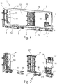
Figur 2- die
Anordnung gemäß Figur 1 ohne ein Wand-Profilteil des Schubladenwandelements, Figur 3- ein erstes Füllelement und
Figur 4- weitere Füllelemente an einer Frontanbindungseinheit.
- FIG. 1
- a drawer wall element according to the invention with a rear wall and a front connection unit in a perspective view, with parts of the drawer wall element being omitted,
- FIG. 2
- the arrangement according to
FIG. 1 without a wall profile part of the drawer wall element, - FIG. 3
- a first filling element and
- FIG. 4
- additional filling elements on a front connection unit.
Zur Darstellung des Inneren des Kammerabschnitts 2 ist der Innenwand-Blechabschnitt 4 nur mit dessen Randbereichen dargestellt. An dem Wand-Profilteil 3 sind vier identisch ausgebildete Bodenaufnahme-Profilteile 6, 7, 8 und 9 fest angeschweißt vorhanden. Die vier Bodenaufnahme-Profilteile 6, 7, 8, 9 sind ebenfalls aus Blechmaterial mit mehreren Umbiegungen bzw. ausgestanzten Bereichen ausgebildet. Jedes Bodenaufnahme-Profilteil 6 bis 9 umfasst jeweils einen Auflageflächenbereich 11 zur unterseitigen Abstützung eines nicht dargestellten Schubladenbodens, der am Schubladenwandelement 1 mit einem Abschnitt eines Längsrandes einsetzbar ist. Zwischen den Bodenaufnahme-Profilteilen 6 und 7, 7 und 8 und 8 und 9 ergibt sich jeweils ein freibleibender Zwischenbereich 12 ohne ein Bodenaufnahme-Profilteil.To illustrate the interior of the
Zur Verbindung des Schubladenwandelements 1 mit einer nicht dargestellten Rückwand einer mit dem Schubladenwandelement 1 erstellbaren Schublade ist an einem rückwärtigen Bereich des Schubladenwandelements 1 eine Schubladen-Rückwandanbindungseinheit 14 angebracht, die innenseitig mit einem Abschnitt 15 am Außenwand-Blechabschnitt 5 fixiert ist und teilweise in den Kammerabschnitt 2 hineinreicht. Die Schubladen-Rückwandanbindungseinheit 14 umfasst außerdem einen Abschnitt 16, der winklig zum Abschnitt 15 ausgerichtet ist und am hinteren Ende des Innenwand-Blechabschnitts 4 über dessen gesamte Höhe abgewinkelt vorsteht.To connect the
An einem frontseitigen Endbereich des Schubladenwandelements 1 ist außerdem eine Schubladen-Frontanbindungseinheit 17 in einem Hohlvolumen 13 des Kammerabschnitts 2 vorhanden.In addition, a drawer
Zur Stabilisierung bzw. Versteifung des Schubladenwandelements 1 und für eine Abstimmung eines Klang- bzw.To stabilize or stiffen the
Geräuschverhaltens des Schubladenwandelements 1 im fertig montierten Nutzzustand der mit dem Schubladenwandelements 1 zusammengebauten Schublade sind am Schubladenwandelement 1 im Hohlvolumen 13 mehrere Füllstücke aus jeweils separaten Bauteilen eingesetzt vorhanden und darin eingespannt. Bei einem Anstoßen eines Gegenstandes oder einer Person an die Schublade bzw. an das Schubladenwandelement 1 oder aufgrund eines anderen mechanischen Wirkzusammenhangs kann bedingt durch den hohlen Kammerabschnitt 2 die Schublade bzw. das Schubladenwandelement 1 bzw. dessen Innenwand-Blechabschnitt 4 und/oder dessen Außenwand-Blechabschnitt 5 in Vibrationen versetzt werden, womit Geräusche in einer vergleichsweise hohen Tonlage entstehen, was unerwünscht ist.Noise behavior of the
Um dies zu vermeiden, werden die Füllstücke im Kammerabschnitt 2 vorgesehen. Die Füllstücke umfassen bei dem Schubladenwandelement 1 ein Basis-Füllelement 18, ein rückseitiges Füllelement 19, welches an der Schubladen-Rückwandanbindungseinheit 14 angeordnet ist und drei weitere Hilfs-Füllelemente 20, 21 und 22, welche an der Schubladen-Frontanbindungseinheit 17 lösbar aufgenommen zum Beispiel aufgesteckt sind.To avoid this, the patches are provided in the
Sämtliche Füllelemente bzw. Füllstücke 18 bis 22 bestehen aus einem geeigneten, insbesondere geräuschdämpfenden Kunststoffmaterial und weisen im eingesetzten Zustand gemäß
Das
Vorteilhafterweise kann es an einem Schubladenwandelement derart eingerichtet sein, dass exakt unterhalb eines Basis-Füllelements 18 ein entsprechendes Bodenaufnahme-Profilteil mittig positioniert ist. In den
Am Basis-Füllelement 18 sind außerdem insgesamt sechs leicht gebogen verlaufende endseitig freie Federelemente 27 ausgebildet, welche gemäß P2 leicht ausfedern können. Die Federelemente 27 sind konvex gewölbt in Richtung einer Innenseite des Innenwand-Blechabschnitts 4. Das Basis-Füllelement 18 weist einen außen umlaufenden Rahmenteil 28 auf, mit Aussparungen bzw. Materialfreilassungen in einem vom Rahmenteil 28 umrahmten inneren Bereich des Basis-Füllelements 18.At the base-filling
Am Basis-Füllelement 18 sind auf einer linken Hälfte und einer rechten Hälfte jeweils drei Federelemente 27 übereinander in einem oberen Abschnitt 18a, einem mittleren Abschnitt 18b und in einem unteren Abschnitt 18c des Basis-Füllelements 18 ausgebildet und am Rahmenteil 28 verbunden über jeweils ein Biegegelenk. Die Federelemente 27 führen zu einer definierten Vorspannung im eingeschobenen Zustand im Kammerabschnitt 2, wobei die Federelemente 27 vorgespannt an der Innenseite des Innenwand-Blechabschnitts 4 anliegen, sodass die Federelemente 27 im Wesentlichen eine quer zur Längsrichtung des Schubladenwandelements 1 versteifende bzw. stabilisierende Wirkung durch das Basis-Füllelement 18 im Kammerabschnitt 2 bereitstellen.At the base-filling
Eine entsprechende versteifende bzw. stabilisierende Wirkung in vertikaler Richtung erbringt insbesondere der Federsteg 24.A corresponding stiffening or stabilizing effect in the vertical direction is provided in particular by the
Oben an der Innenseite des Verbindungsabschnitts 10 stützt sich das Basis-Füllelement 18 über einen vertikalen Rahmensteg 28a ab.At the top of the inside of the connecting
An der einzeln vergrößert dargestellten Schubladen-Frontanbindungseinheit 17 gemäß
Die Hilfsfüllelemente 20 bis 22 dienen insbesondere zum Verspannen des Kammerabschnitts 2 im vorderen Endbereich bzw. das Füllelement 19 an der Rückwandanbindungseinheit 15 im hinteren Endbereich zwischen Innenseiten des Innenwand-Blechabschnitts 4 und des Außenwand-Blechabschnitts 5 und können in diese Richtung etwas federnd sich verhalten insbesondere um Belastungs- bzw. Spannungsspitzen auf die Innenwand-Blechabschnitte 4 bzw. Außenwand-Blechabschnitte 5 aufzunehmen. Hierzu sind Federelemente 19a bzw. 20a, 21a und 22a an den Füllelementen 19 bzw. 20-22 vorhanden.The
Mit der Stabilisierung und Versteifung durch die Füllelemente 18 bis 22 wird außerdem auch eine klangliche Anpassung dahingehend erzielt, dass im Bereich des Kammerabschnitts 2 ein Anklingen durch eine Einwirkung bzw. ein Anstoßen von außen an das Schubladenwandelement 1 vergleichsweise dumpfer klingt bzw. Schwingungsenergie absorbiert wird und weniger laut klingt.With the stabilization and stiffening by the filling
Zusätzlich kann in das Hohlvolumen 13 des Kammerabschnitts 2 ausfüllendes bzw. geräuschdämpfendes Material wie beispielsweise schäumendes bzw. selbsthärtendes Material wie Polyurethan eingebracht werden, um stabilisierend zu wirken und Geräusche am Schubladenwandelement 1 zu dämpfen.In addition, in the
- 11
- SchubladenwandelementDrawer wall element
- 22
- Kammerabschnittchamber section
- 33
- Wand-ProfilteilWall profile part
- 44
- Innenwand-BlechabschnittInterior wall sheet metal section
- 55
- Außenwand-BlechabschnittExternal wall sheet metal section
- 66
- Bodenaufnahme-ProfilteilFloor recording profile part
- 77
- Bodenaufnahme-ProfilteilFloor recording profile part
- 88th
- Bodenaufnahme-ProfilteilFloor recording profile part
- 99
- Bodenaufnahme-ProfilteilFloor recording profile part
- 1010
- Verbindungsabschnittconnecting portion
- 1111
- AuflageflächenbereichContact surface area
- 1212
- Zwischenbereichintermediate area
- 1313
- Hohlvolumenvoid volume
- 1414
- Schubladen-RückwandanbindungseinheitDrawers backplane connection unit
- 1515
- Abschnittsection
- 1616
- Abschnittsection
- 1717
- Schubladen-FrontanbindungseinheitDrawer front access unit
- 1818
- Basis-FüllelementBasic filler
- 18a18a
- Abschnittsection
- 18b18b
- Abschnittsection
- 18c18c
- Abschnittsection
- 1919
- Füllelementfiller
- 19a19a
- Federelementspring element
- 2020
- Hilfs-FüllelementAuxiliary filler
- 20a20a
- Federelementspring element
- 2121
- Hilfs-FüllelementAuxiliary filler
- 21a21a
- Federelementspring element
- 2222
- Hilfs-FüllelementAuxiliary filler
- 22a22a
- Federelementspring element
- 2323
- Federbogenspring bow
- 2424
- Federstegspring bar
- 2525
- Aussparungrecess
- 2626
- Stegabschnittweb section
- 2727
- Federelementspring element
- 2828
- Rahmenteilframe part
- 28a28a
- Rahmenstegframe stay
Claims (10)
- Drawer panel unit (1) for a drawer, wherein an edge section of a drawer bottom panel can be inserted in order to form a drawer side panel adjacent to the drawer bottom panel, whereby drawer panel unit (1) comprises a panel profile part (3) and a bottom receptacle profile part (6-9), whereby, in drawer panel unit (1), a supporting surface (11) existing on bottom receptacle profile part (6-9) is provided for supporting the underside of a drawer bottom panel that can be inserted in drawer panel unit (1), and whereby panel profile part (3) comprises a compartment section (2) with a sheet metal inside panel (4) and a sheet metal outside panel (5), which are spaced opposite each other over a width dimension of drawer panel unit (1) and connected above by a connecting section (10), whereby at least one infill unit (18-22) is inserted in compartment section (2), this unit comprising at least one pretensioned spring unit (19a, 20a, 21a, 22a, 24, 27) defined in the inserted condition, characterised in that the panel profile part (3) and the bottom receptacle profile part (6-9) are each designed as separate and mutually matched components in a sheet metal material, and, aligned with each other, are connected together to make drawer panel unit (1).
- Drawer panel unit according to Claim 1, characterised in that the at least one infill unit (18-22) is designed such that it can be pushed into a panel profile part (3).
- Drawer panel unit according to one of the preceding claims, characterised in that the infill unit (18) is designed such that, in the inserted condition, it is elastically supported at bottom receptacle profile part (8).
- Drawer panel unit according to one of the preceding claims, characterised in that at least one infill unit (19) is provided on a drawer back panel linking unit (14).
- Drawer panel unit according to one of the preceding claims, characterised in that at least one infill unit (20-22) is provided on a drawer front linking unit (17).
- Drawer panel unit according to one of the preceding claims, characterised in that a bridging section (26) is provided on the bottom receptacle profile part (6-9), spaced above supporting surface (11), the bridging section being linked at a contact section angled upwards relative to supporting surface (11) by a bend in the material.
- Drawer panel unit according to one of the preceding claims, characterised in that bridging section (26) bridges a distance between outside sheet metal panel (5) and inside sheet metal panel (4).
- Drawer panel unit according to Claim 7, characterised in that infill unit (18) is supported on bridging section (26).
- Drawer panel unit according to one of the preceding claims, characterised in that infill unit (18) has a spring strip (24) at its lower edge.
- Furniture item with a drawer panel unit (1) according to one of Claims 1 to 9.
Applications Claiming Priority (2)
| Application Number | Priority Date | Filing Date | Title |
|---|---|---|---|
| DE201320011425 DE202013011425U1 (en) | 2013-12-20 | 2013-12-20 | Drawer wall element and filling element for a drawer wall and furniture |
| PCT/EP2014/078573 WO2015091867A1 (en) | 2013-12-20 | 2014-12-18 | Drawer wall element and filler element for a drawer wall, and item of furniture |
Publications (2)
| Publication Number | Publication Date |
|---|---|
| EP3082509A1 EP3082509A1 (en) | 2016-10-26 |
| EP3082509B1 true EP3082509B1 (en) | 2018-04-04 |
Family
ID=52273128
Family Applications (1)
| Application Number | Title | Priority Date | Filing Date |
|---|---|---|---|
| EP14821155.0A Active EP3082509B1 (en) | 2013-12-20 | 2014-12-18 | Drawer wall element with filler element for a drawer wall, and item of furniture |
Country Status (5)
| Country | Link |
|---|---|
| US (1) | US10117514B2 (en) |
| EP (1) | EP3082509B1 (en) |
| CN (1) | CN105828668B (en) |
| DE (1) | DE202013011425U1 (en) |
| WO (1) | WO2015091867A1 (en) |
Cited By (1)
| Publication number | Priority date | Publication date | Assignee | Title |
|---|---|---|---|---|
| DE102019111861A1 (en) * | 2019-05-07 | 2020-11-12 | Paul Hettich Gmbh & Co. Kg | Drawer wall element |
Families Citing this family (9)
| Publication number | Priority date | Publication date | Assignee | Title |
|---|---|---|---|---|
| DE202013011421U1 (en) * | 2013-12-20 | 2015-03-23 | Grass Gmbh | Schubladenfrontanbindungselnheit |
| DE202014104930U1 (en) * | 2014-10-16 | 2016-01-19 | Grass Gmbh | Connecting device for a wall element of a drawer and wall structure and furniture |
| DE102015110560A1 (en) * | 2015-07-01 | 2017-01-05 | Form Orange Produktentwicklung | Drawer with a base plate, two side walls, a rear wall and a panel |
| DE102017121597A1 (en) | 2016-11-25 | 2018-05-30 | Paul Hettich Gmbh & Co. Kg | drawer |
| DE102017102644A1 (en) * | 2017-02-10 | 2018-08-16 | Paul Hettich Gmbh & Co. Kg | drawer |
| AT519781B1 (en) * | 2017-04-05 | 2020-07-15 | Blum Gmbh Julius | Drawer wall |
| DE102018203448A1 (en) * | 2018-03-07 | 2019-09-12 | Grass Gmbh | Panel for a movable furniture part |
| DE102018123054A1 (en) * | 2018-09-19 | 2020-03-19 | Paul Hettich Gmbh & Co. Kg | Drawer and unit from a pull-out guide and a drawer |
| DE102019113101A1 (en) * | 2019-05-17 | 2020-11-19 | Paul Hettich Gmbh & Co. Kg | Side frame for a drawer |
Family Cites Families (16)
| Publication number | Priority date | Publication date | Assignee | Title |
|---|---|---|---|---|
| GB1189907A (en) * | 1967-10-16 | 1970-04-29 | Leslie William Llewelly Alston | Improvements in or relating to Drawers for Furniture |
| GB1507498A (en) * | 1975-05-30 | 1978-04-12 | Swish Prod | Structural elements |
| US4128284A (en) * | 1977-03-31 | 1978-12-05 | Mackenzie King Holdings Limited | Construction of articles of furniture |
| DE4004332A1 (en) * | 1990-02-13 | 1991-08-14 | Lautenschlaeger Kg Karl | Smooth-running drawer sides etc. - which are made of hollow metal sections of suitable profiles filled with e.g. polyurethane foam so as to run easily and quietly |
| AT401853B (en) * | 1992-10-15 | 1996-12-27 | Blum Gmbh Julius | Drawer side |
| AT407332B (en) * | 1997-03-21 | 2001-02-26 | Blum Gmbh Julius | DRAWER |
| EP1932448B1 (en) * | 2006-12-15 | 2010-04-14 | Harn Marketing Sdn. Bhd. | Corner fitting |
| DE202008002447U1 (en) * | 2008-02-21 | 2009-06-25 | Paul Hettich Gmbh & Co. Kg | Drawer made of sheet metal |
| JP2011517412A (en) * | 2008-09-26 | 2011-06-09 | サメト カリプ ヴェ マデミ エシャ サナイ ヴェ ティカレット アノニム サーケティ | Linkable corner fixture for easily attachable and removable drawers |
| AT13532U1 (en) * | 2010-02-03 | 2014-02-15 | Blum Gmbh Julius | drawer system |
| CN201641069U (en) * | 2010-02-10 | 2010-11-24 | 金竣企业股份有限公司 | Automatic opening-closing buffer device of drawer |
| AT510016B1 (en) * | 2010-11-23 | 2012-01-15 | Blum Gmbh Julius | DRAWER WALL WITH AN INTERNAL WALL AND AN EXTERNAL WALL |
| DE202011000393U1 (en) * | 2011-02-21 | 2011-04-28 | Anton Schneider Gmbh & Co Kg | Bottom plate with reinforcement on the underside |
| CN203041349U (en) * | 2012-12-28 | 2013-07-10 | 伍志勇 | Side board structure of drawer sliding rail |
| CN203137617U (en) * | 2013-03-21 | 2013-08-21 | 伍志勇 | Detachable and installable locking mechanism of drawer sliding rail and side plate |
| CN103142043B (en) * | 2013-03-21 | 2015-05-13 | 伍志勇 | Dismountable locking mechanism of drawer slide rail and side plate |
-
2013
- 2013-12-20 DE DE201320011425 patent/DE202013011425U1/en not_active Expired - Lifetime
-
2014
- 2014-12-18 CN CN201480069121.XA patent/CN105828668B/en active Active
- 2014-12-18 WO PCT/EP2014/078573 patent/WO2015091867A1/en active Application Filing
- 2014-12-18 EP EP14821155.0A patent/EP3082509B1/en active Active
-
2016
- 2016-06-16 US US15/183,987 patent/US10117514B2/en active Active
Cited By (2)
| Publication number | Priority date | Publication date | Assignee | Title |
|---|---|---|---|---|
| DE102019111861A1 (en) * | 2019-05-07 | 2020-11-12 | Paul Hettich Gmbh & Co. Kg | Drawer wall element |
| WO2020225027A1 (en) | 2019-05-07 | 2020-11-12 | Paul Hettich Gmbh & Co. Kg | Drawer wall element |
Also Published As
| Publication number | Publication date |
|---|---|
| US20160360884A1 (en) | 2016-12-15 |
| CN105828668B (en) | 2019-01-25 |
| DE202013011425U1 (en) | 2015-03-23 |
| WO2015091867A1 (en) | 2015-06-25 |
| EP3082509A1 (en) | 2016-10-26 |
| US10117514B2 (en) | 2018-11-06 |
| CN105828668A (en) | 2016-08-03 |
Similar Documents
| Publication | Publication Date | Title |
|---|---|---|
| EP3082509B1 (en) | Drawer wall element with filler element for a drawer wall, and item of furniture | |
| DE102017128750A1 (en) | Guide rail of a guide system, guide system and furniture | |
| EP2010023A1 (en) | Shelf panel | |
| EP2526823A1 (en) | Cabinet with pull-out frame | |
| DE102015109016B4 (en) | Suspension frame for waste containers in furniture pull-outs | |
| DE102016125028A1 (en) | drawer | |
| EP3082511B1 (en) | Drawer front connection unit | |
| EP3082507A2 (en) | Furniture drawer and drawer wall element for a drawer | |
| DE202009000241U1 (en) | Rail for hanging cabinets | |
| EP3078864A1 (en) | Furniture body | |
| DE102019111655A1 (en) | Body rail with stiffening element | |
| EP3009041B1 (en) | Wall component, drawer with such a wall component and piece of furniture | |
| EP1882143A1 (en) | Adjusting rail | |
| EP4193880B1 (en) | Sheet metal compartment base with sound insulation | |
| DE2949891A1 (en) | MOUNTABLE SHELF | |
| EP2496114A1 (en) | Stabilizer shoe for a rack for supporting objects | |
| DE202021100338U1 (en) | Furniture frame | |
| DE202017102673U1 (en) | Shelf with reinforced sub-carrier | |
| EP1776901A1 (en) | Shelf support with clamping hooks | |
| DE102015109306A1 (en) | Gratings, in particular for use as a shelf for plate racks or heavy duty racks, with two longitudinal sides and cross members arranged between the longitudinal sides | |
| EP3082510B1 (en) | Drawer wall element and furniture drawer | |
| EP3847927A1 (en) | Sheet metal sheet with sound insulation | |
| DE102011113298B4 (en) | shelf combination | |
| EP1426698A1 (en) | Radiator cover grid | |
| DE102017120790A1 (en) | Connecting element for connecting profiles |
Legal Events
| Date | Code | Title | Description |
|---|---|---|---|
| PUAI | Public reference made under article 153(3) epc to a published international application that has entered the european phase |
Free format text: ORIGINAL CODE: 0009012 |
|
| 17P | Request for examination filed |
Effective date: 20160510 |
|
| AK | Designated contracting states |
Kind code of ref document: A1 Designated state(s): AL AT BE BG CH CY CZ DE DK EE ES FI FR GB GR HR HU IE IS IT LI LT LU LV MC MK MT NL NO PL PT RO RS SE SI SK SM TR |
|
| AX | Request for extension of the european patent |
Extension state: BA ME |
|
| DAX | Request for extension of the european patent (deleted) | ||
| REG | Reference to a national code |
Ref country code: DE Ref legal event code: R079 Ref document number: 502014007887 Country of ref document: DE Free format text: PREVIOUS MAIN CLASS: A47B0088000000 Ipc: A47B0088900000 |
|
| GRAP | Despatch of communication of intention to grant a patent |
Free format text: ORIGINAL CODE: EPIDOSNIGR1 |
|
| RIC1 | Information provided on ipc code assigned before grant |
Ipc: A47B 88/90 20170101AFI20171019BHEP |
|
| INTG | Intention to grant announced |
Effective date: 20171117 |
|
| GRAS | Grant fee paid |
Free format text: ORIGINAL CODE: EPIDOSNIGR3 |
|
| GRAA | (expected) grant |
Free format text: ORIGINAL CODE: 0009210 |
|
| AK | Designated contracting states |
Kind code of ref document: B1 Designated state(s): AL AT BE BG CH CY CZ DE DK EE ES FI FR GB GR HR HU IE IS IT LI LT LU LV MC MK MT NL NO PL PT RO RS SE SI SK SM TR |
|
| REG | Reference to a national code |
Ref country code: GB Ref legal event code: FG4D Free format text: NOT ENGLISH |
|
| REG | Reference to a national code |
Ref country code: CH Ref legal event code: EP |
|
| REG | Reference to a national code |
Ref country code: AT Ref legal event code: REF Ref document number: 984626 Country of ref document: AT Kind code of ref document: T Effective date: 20180415 |
|
| REG | Reference to a national code |
Ref country code: IE Ref legal event code: FG4D Free format text: LANGUAGE OF EP DOCUMENT: GERMAN |
|
| REG | Reference to a national code |
Ref country code: DE Ref legal event code: R096 Ref document number: 502014007887 Country of ref document: DE |
|
| REG | Reference to a national code |
Ref country code: NL Ref legal event code: MP Effective date: 20180404 |
|
| REG | Reference to a national code |
Ref country code: LT Ref legal event code: MG4D |
|
| PG25 | Lapsed in a contracting state [announced via postgrant information from national office to epo] |
Ref country code: NL Free format text: LAPSE BECAUSE OF FAILURE TO SUBMIT A TRANSLATION OF THE DESCRIPTION OR TO PAY THE FEE WITHIN THE PRESCRIBED TIME-LIMIT Effective date: 20180404 |
|
| PG25 | Lapsed in a contracting state [announced via postgrant information from national office to epo] |
Ref country code: BG Free format text: LAPSE BECAUSE OF FAILURE TO SUBMIT A TRANSLATION OF THE DESCRIPTION OR TO PAY THE FEE WITHIN THE PRESCRIBED TIME-LIMIT Effective date: 20180704 Ref country code: FI Free format text: LAPSE BECAUSE OF FAILURE TO SUBMIT A TRANSLATION OF THE DESCRIPTION OR TO PAY THE FEE WITHIN THE PRESCRIBED TIME-LIMIT Effective date: 20180404 Ref country code: NO Free format text: LAPSE BECAUSE OF FAILURE TO SUBMIT A TRANSLATION OF THE DESCRIPTION OR TO PAY THE FEE WITHIN THE PRESCRIBED TIME-LIMIT Effective date: 20180704 Ref country code: SE Free format text: LAPSE BECAUSE OF FAILURE TO SUBMIT A TRANSLATION OF THE DESCRIPTION OR TO PAY THE FEE WITHIN THE PRESCRIBED TIME-LIMIT Effective date: 20180404 Ref country code: AL Free format text: LAPSE BECAUSE OF FAILURE TO SUBMIT A TRANSLATION OF THE DESCRIPTION OR TO PAY THE FEE WITHIN THE PRESCRIBED TIME-LIMIT Effective date: 20180404 Ref country code: LT Free format text: LAPSE BECAUSE OF FAILURE TO SUBMIT A TRANSLATION OF THE DESCRIPTION OR TO PAY THE FEE WITHIN THE PRESCRIBED TIME-LIMIT Effective date: 20180404 Ref country code: PL Free format text: LAPSE BECAUSE OF FAILURE TO SUBMIT A TRANSLATION OF THE DESCRIPTION OR TO PAY THE FEE WITHIN THE PRESCRIBED TIME-LIMIT Effective date: 20180404 Ref country code: ES Free format text: LAPSE BECAUSE OF FAILURE TO SUBMIT A TRANSLATION OF THE DESCRIPTION OR TO PAY THE FEE WITHIN THE PRESCRIBED TIME-LIMIT Effective date: 20180404 |
|
| PG25 | Lapsed in a contracting state [announced via postgrant information from national office to epo] |
Ref country code: HR Free format text: LAPSE BECAUSE OF FAILURE TO SUBMIT A TRANSLATION OF THE DESCRIPTION OR TO PAY THE FEE WITHIN THE PRESCRIBED TIME-LIMIT Effective date: 20180404 Ref country code: GR Free format text: LAPSE BECAUSE OF FAILURE TO SUBMIT A TRANSLATION OF THE DESCRIPTION OR TO PAY THE FEE WITHIN THE PRESCRIBED TIME-LIMIT Effective date: 20180705 Ref country code: LV Free format text: LAPSE BECAUSE OF FAILURE TO SUBMIT A TRANSLATION OF THE DESCRIPTION OR TO PAY THE FEE WITHIN THE PRESCRIBED TIME-LIMIT Effective date: 20180404 Ref country code: RS Free format text: LAPSE BECAUSE OF FAILURE TO SUBMIT A TRANSLATION OF THE DESCRIPTION OR TO PAY THE FEE WITHIN THE PRESCRIBED TIME-LIMIT Effective date: 20180404 |
|
| PG25 | Lapsed in a contracting state [announced via postgrant information from national office to epo] |
Ref country code: PT Free format text: LAPSE BECAUSE OF FAILURE TO SUBMIT A TRANSLATION OF THE DESCRIPTION OR TO PAY THE FEE WITHIN THE PRESCRIBED TIME-LIMIT Effective date: 20180806 |
|
| REG | Reference to a national code |
Ref country code: DE Ref legal event code: R097 Ref document number: 502014007887 Country of ref document: DE |
|
| PG25 | Lapsed in a contracting state [announced via postgrant information from national office to epo] |
Ref country code: RO Free format text: LAPSE BECAUSE OF FAILURE TO SUBMIT A TRANSLATION OF THE DESCRIPTION OR TO PAY THE FEE WITHIN THE PRESCRIBED TIME-LIMIT Effective date: 20180404 Ref country code: SK Free format text: LAPSE BECAUSE OF FAILURE TO SUBMIT A TRANSLATION OF THE DESCRIPTION OR TO PAY THE FEE WITHIN THE PRESCRIBED TIME-LIMIT Effective date: 20180404 Ref country code: CZ Free format text: LAPSE BECAUSE OF FAILURE TO SUBMIT A TRANSLATION OF THE DESCRIPTION OR TO PAY THE FEE WITHIN THE PRESCRIBED TIME-LIMIT Effective date: 20180404 Ref country code: EE Free format text: LAPSE BECAUSE OF FAILURE TO SUBMIT A TRANSLATION OF THE DESCRIPTION OR TO PAY THE FEE WITHIN THE PRESCRIBED TIME-LIMIT Effective date: 20180404 Ref country code: DK Free format text: LAPSE BECAUSE OF FAILURE TO SUBMIT A TRANSLATION OF THE DESCRIPTION OR TO PAY THE FEE WITHIN THE PRESCRIBED TIME-LIMIT Effective date: 20180404 |
|
| PLBE | No opposition filed within time limit |
Free format text: ORIGINAL CODE: 0009261 |
|
| STAA | Information on the status of an ep patent application or granted ep patent |
Free format text: STATUS: NO OPPOSITION FILED WITHIN TIME LIMIT |
|
| PG25 | Lapsed in a contracting state [announced via postgrant information from national office to epo] |
Ref country code: IT Free format text: LAPSE BECAUSE OF FAILURE TO SUBMIT A TRANSLATION OF THE DESCRIPTION OR TO PAY THE FEE WITHIN THE PRESCRIBED TIME-LIMIT Effective date: 20180404 Ref country code: SM Free format text: LAPSE BECAUSE OF FAILURE TO SUBMIT A TRANSLATION OF THE DESCRIPTION OR TO PAY THE FEE WITHIN THE PRESCRIBED TIME-LIMIT Effective date: 20180404 |
|
| 26N | No opposition filed |
Effective date: 20190107 |
|
| PG25 | Lapsed in a contracting state [announced via postgrant information from national office to epo] |
Ref country code: SI Free format text: LAPSE BECAUSE OF FAILURE TO SUBMIT A TRANSLATION OF THE DESCRIPTION OR TO PAY THE FEE WITHIN THE PRESCRIBED TIME-LIMIT Effective date: 20180404 |
|
| REG | Reference to a national code |
Ref country code: CH Ref legal event code: PL |
|
| GBPC | Gb: european patent ceased through non-payment of renewal fee |
Effective date: 20181218 |
|
| PG25 | Lapsed in a contracting state [announced via postgrant information from national office to epo] |
Ref country code: LU Free format text: LAPSE BECAUSE OF NON-PAYMENT OF DUE FEES Effective date: 20181218 Ref country code: MC Free format text: LAPSE BECAUSE OF FAILURE TO SUBMIT A TRANSLATION OF THE DESCRIPTION OR TO PAY THE FEE WITHIN THE PRESCRIBED TIME-LIMIT Effective date: 20180404 |
|
| REG | Reference to a national code |
Ref country code: IE Ref legal event code: MM4A |
|
| REG | Reference to a national code |
Ref country code: BE Ref legal event code: MM Effective date: 20181231 |
|
| PG25 | Lapsed in a contracting state [announced via postgrant information from national office to epo] |
Ref country code: IE Free format text: LAPSE BECAUSE OF NON-PAYMENT OF DUE FEES Effective date: 20181218 Ref country code: FR Free format text: LAPSE BECAUSE OF NON-PAYMENT OF DUE FEES Effective date: 20181231 |
|
| PG25 | Lapsed in a contracting state [announced via postgrant information from national office to epo] |
Ref country code: BE Free format text: LAPSE BECAUSE OF NON-PAYMENT OF DUE FEES Effective date: 20181231 |
|
| PG25 | Lapsed in a contracting state [announced via postgrant information from national office to epo] |
Ref country code: GB Free format text: LAPSE BECAUSE OF NON-PAYMENT OF DUE FEES Effective date: 20181218 Ref country code: CH Free format text: LAPSE BECAUSE OF NON-PAYMENT OF DUE FEES Effective date: 20181231 Ref country code: LI Free format text: LAPSE BECAUSE OF NON-PAYMENT OF DUE FEES Effective date: 20181231 |
|
| PG25 | Lapsed in a contracting state [announced via postgrant information from national office to epo] |
Ref country code: MT Free format text: LAPSE BECAUSE OF FAILURE TO SUBMIT A TRANSLATION OF THE DESCRIPTION OR TO PAY THE FEE WITHIN THE PRESCRIBED TIME-LIMIT Effective date: 20180404 |
|
| PG25 | Lapsed in a contracting state [announced via postgrant information from national office to epo] |
Ref country code: TR Free format text: LAPSE BECAUSE OF FAILURE TO SUBMIT A TRANSLATION OF THE DESCRIPTION OR TO PAY THE FEE WITHIN THE PRESCRIBED TIME-LIMIT Effective date: 20180404 |
|
| PGFP | Annual fee paid to national office [announced via postgrant information from national office to epo] |
Ref country code: AT Payment date: 20191127 Year of fee payment: 6 |
|
| PG25 | Lapsed in a contracting state [announced via postgrant information from national office to epo] |
Ref country code: MK Free format text: LAPSE BECAUSE OF NON-PAYMENT OF DUE FEES Effective date: 20180404 Ref country code: HU Free format text: LAPSE BECAUSE OF FAILURE TO SUBMIT A TRANSLATION OF THE DESCRIPTION OR TO PAY THE FEE WITHIN THE PRESCRIBED TIME-LIMIT; INVALID AB INITIO Effective date: 20141218 Ref country code: CY Free format text: LAPSE BECAUSE OF FAILURE TO SUBMIT A TRANSLATION OF THE DESCRIPTION OR TO PAY THE FEE WITHIN THE PRESCRIBED TIME-LIMIT Effective date: 20180404 |
|
| PG25 | Lapsed in a contracting state [announced via postgrant information from national office to epo] |
Ref country code: IS Free format text: LAPSE BECAUSE OF FAILURE TO SUBMIT A TRANSLATION OF THE DESCRIPTION OR TO PAY THE FEE WITHIN THE PRESCRIBED TIME-LIMIT Effective date: 20180804 |
|
| REG | Reference to a national code |
Ref country code: AT Ref legal event code: MM01 Ref document number: 984626 Country of ref document: AT Kind code of ref document: T Effective date: 20201218 |
|
| PG25 | Lapsed in a contracting state [announced via postgrant information from national office to epo] |
Ref country code: AT Free format text: LAPSE BECAUSE OF NON-PAYMENT OF DUE FEES Effective date: 20201218 |
|
| PGFP | Annual fee paid to national office [announced via postgrant information from national office to epo] |
Ref country code: DE Payment date: 20231107 Year of fee payment: 10 |