EP3082001A1 - Verfahren zum erweitern einer automatisierungseinrichtung mittels einem virtuellen feldgerät sowie automatisierungseinrichtung - Google Patents
Verfahren zum erweitern einer automatisierungseinrichtung mittels einem virtuellen feldgerät sowie automatisierungseinrichtung Download PDFInfo
- Publication number
- EP3082001A1 EP3082001A1 EP15163409.4A EP15163409A EP3082001A1 EP 3082001 A1 EP3082001 A1 EP 3082001A1 EP 15163409 A EP15163409 A EP 15163409A EP 3082001 A1 EP3082001 A1 EP 3082001A1
- Authority
- EP
- European Patent Office
- Prior art keywords
- control
- communication
- automation device
- load
- automation
- Prior art date
- Legal status (The legal status is an assumption and is not a legal conclusion. Google has not performed a legal analysis and makes no representation as to the accuracy of the status listed.)
- Granted
Links
- 238000000034 method Methods 0.000 title claims abstract description 19
- 238000004891 communication Methods 0.000 claims abstract description 66
- 238000004886 process control Methods 0.000 claims description 19
- 238000012545 processing Methods 0.000 claims description 12
- 230000008569 process Effects 0.000 claims description 10
- 238000012407 engineering method Methods 0.000 claims description 5
- 238000012806 monitoring device Methods 0.000 claims description 3
- 230000003213 activating effect Effects 0.000 claims 1
- 230000006870 function Effects 0.000 description 9
- 238000004519 manufacturing process Methods 0.000 description 8
- 230000001632 homeopathic effect Effects 0.000 description 2
- 230000010354 integration Effects 0.000 description 2
- 238000012360 testing method Methods 0.000 description 2
- 230000009471 action Effects 0.000 description 1
- 230000004913 activation Effects 0.000 description 1
- 238000010586 diagram Methods 0.000 description 1
- 239000003337 fertilizer Substances 0.000 description 1
- 238000010438 heat treatment Methods 0.000 description 1
- 230000003993 interaction Effects 0.000 description 1
- 239000000463 material Substances 0.000 description 1
- 230000002093 peripheral effect Effects 0.000 description 1
- 238000002360 preparation method Methods 0.000 description 1
- 230000003068 static effect Effects 0.000 description 1
- 238000003756 stirring Methods 0.000 description 1
- 238000003860 storage Methods 0.000 description 1
- 238000004808 supercritical fluid chromatography Methods 0.000 description 1
- 239000000979 synthetic dye Substances 0.000 description 1
- 229920003002 synthetic resin Polymers 0.000 description 1
- 239000000057 synthetic resin Substances 0.000 description 1
- 230000007704 transition Effects 0.000 description 1
Images

Classifications
-
- G—PHYSICS
- G05—CONTROLLING; REGULATING
- G05B—CONTROL OR REGULATING SYSTEMS IN GENERAL; FUNCTIONAL ELEMENTS OF SUCH SYSTEMS; MONITORING OR TESTING ARRANGEMENTS FOR SUCH SYSTEMS OR ELEMENTS
- G05B19/00—Programme-control systems
- G05B19/02—Programme-control systems electric
- G05B19/04—Programme control other than numerical control, i.e. in sequence controllers or logic controllers
- G05B19/048—Monitoring; Safety
-
- G—PHYSICS
- G05—CONTROLLING; REGULATING
- G05B—CONTROL OR REGULATING SYSTEMS IN GENERAL; FUNCTIONAL ELEMENTS OF SUCH SYSTEMS; MONITORING OR TESTING ARRANGEMENTS FOR SUCH SYSTEMS OR ELEMENTS
- G05B19/00—Programme-control systems
- G05B19/02—Programme-control systems electric
- G05B19/418—Total factory control, i.e. centrally controlling a plurality of machines, e.g. direct or distributed numerical control [DNC], flexible manufacturing systems [FMS], integrated manufacturing systems [IMS] or computer integrated manufacturing [CIM]
- G05B19/41835—Total factory control, i.e. centrally controlling a plurality of machines, e.g. direct or distributed numerical control [DNC], flexible manufacturing systems [FMS], integrated manufacturing systems [IMS] or computer integrated manufacturing [CIM] characterised by programme execution
-
- G—PHYSICS
- G06—COMPUTING; CALCULATING OR COUNTING
- G06F—ELECTRIC DIGITAL DATA PROCESSING
- G06F30/00—Computer-aided design [CAD]
- G06F30/10—Geometric CAD
- G06F30/17—Mechanical parametric or variational design
-
- G—PHYSICS
- G05—CONTROLLING; REGULATING
- G05B—CONTROL OR REGULATING SYSTEMS IN GENERAL; FUNCTIONAL ELEMENTS OF SUCH SYSTEMS; MONITORING OR TESTING ARRANGEMENTS FOR SUCH SYSTEMS OR ELEMENTS
- G05B19/00—Programme-control systems
- G05B19/02—Programme-control systems electric
- G05B19/04—Programme control other than numerical control, i.e. in sequence controllers or logic controllers
- G05B19/042—Programme control other than numerical control, i.e. in sequence controllers or logic controllers using digital processors
- G05B19/0426—Programming the control sequence
-
- G—PHYSICS
- G05—CONTROLLING; REGULATING
- G05B—CONTROL OR REGULATING SYSTEMS IN GENERAL; FUNCTIONAL ELEMENTS OF SUCH SYSTEMS; MONITORING OR TESTING ARRANGEMENTS FOR SUCH SYSTEMS OR ELEMENTS
- G05B19/00—Programme-control systems
- G05B19/02—Programme-control systems electric
- G05B19/04—Programme control other than numerical control, i.e. in sequence controllers or logic controllers
- G05B19/05—Programmable logic controllers, e.g. simulating logic interconnections of signals according to ladder diagrams or function charts
- G05B19/056—Programming the PLC
-
- G—PHYSICS
- G05—CONTROLLING; REGULATING
- G05B—CONTROL OR REGULATING SYSTEMS IN GENERAL; FUNCTIONAL ELEMENTS OF SUCH SYSTEMS; MONITORING OR TESTING ARRANGEMENTS FOR SUCH SYSTEMS OR ELEMENTS
- G05B19/00—Programme-control systems
- G05B19/02—Programme-control systems electric
- G05B19/418—Total factory control, i.e. centrally controlling a plurality of machines, e.g. direct or distributed numerical control [DNC], flexible manufacturing systems [FMS], integrated manufacturing systems [IMS] or computer integrated manufacturing [CIM]
- G05B19/4183—Total factory control, i.e. centrally controlling a plurality of machines, e.g. direct or distributed numerical control [DNC], flexible manufacturing systems [FMS], integrated manufacturing systems [IMS] or computer integrated manufacturing [CIM] characterised by data acquisition, e.g. workpiece identification
-
- G—PHYSICS
- G06—COMPUTING; CALCULATING OR COUNTING
- G06F—ELECTRIC DIGITAL DATA PROCESSING
- G06F30/00—Computer-aided design [CAD]
- G06F30/20—Design optimisation, verification or simulation
-
- G—PHYSICS
- G05—CONTROLLING; REGULATING
- G05B—CONTROL OR REGULATING SYSTEMS IN GENERAL; FUNCTIONAL ELEMENTS OF SUCH SYSTEMS; MONITORING OR TESTING ARRANGEMENTS FOR SUCH SYSTEMS OR ELEMENTS
- G05B2219/00—Program-control systems
- G05B2219/20—Pc systems
- G05B2219/25—Pc structure of the system
- G05B2219/25428—Field device
-
- G—PHYSICS
- G05—CONTROLLING; REGULATING
- G05B—CONTROL OR REGULATING SYSTEMS IN GENERAL; FUNCTIONAL ELEMENTS OF SUCH SYSTEMS; MONITORING OR TESTING ARRANGEMENTS FOR SUCH SYSTEMS OR ELEMENTS
- G05B2219/00—Program-control systems
- G05B2219/30—Nc systems
- G05B2219/31—From computer integrated manufacturing till monitoring
- G05B2219/31018—Virtual factory, modules in network, can be selected and combined at will
-
- G—PHYSICS
- G05—CONTROLLING; REGULATING
- G05B—CONTROL OR REGULATING SYSTEMS IN GENERAL; FUNCTIONAL ELEMENTS OF SUCH SYSTEMS; MONITORING OR TESTING ARRANGEMENTS FOR SUCH SYSTEMS OR ELEMENTS
- G05B2219/00—Program-control systems
- G05B2219/30—Nc systems
- G05B2219/31—From computer integrated manufacturing till monitoring
- G05B2219/31135—Fieldbus
-
- G—PHYSICS
- G05—CONTROLLING; REGULATING
- G05B—CONTROL OR REGULATING SYSTEMS IN GENERAL; FUNCTIONAL ELEMENTS OF SUCH SYSTEMS; MONITORING OR TESTING ARRANGEMENTS FOR SUCH SYSTEMS OR ELEMENTS
- G05B2219/00—Program-control systems
- G05B2219/30—Nc systems
- G05B2219/31—From computer integrated manufacturing till monitoring
- G05B2219/31229—Supervisor, master, workstation controller, automation, machine control
-
- G—PHYSICS
- G05—CONTROLLING; REGULATING
- G05B—CONTROL OR REGULATING SYSTEMS IN GENERAL; FUNCTIONAL ELEMENTS OF SUCH SYSTEMS; MONITORING OR TESTING ARRANGEMENTS FOR SUCH SYSTEMS OR ELEMENTS
- G05B2219/00—Program-control systems
- G05B2219/30—Nc systems
- G05B2219/32—Operator till task planning
- G05B2219/32128—Gui graphical user interface
Definitions
- the invention relates to a method for expanding an automation device with a field device, wherein the automation device has at least one automation device and at least one field device, which are connected to a communication link, and wherein the automation device is further configured by an engineering method for solving an automation task such that the at least one automation device processes a configured control program during a process control, which comprises a plurality of control blocks.
- the invention relates to an automation device according to the preamble of claim 3 for carrying out the method.
- the power reserves of the controller and the communication network can be estimated as part of the configuration of extensions of the automation device.
- the long-standing experience of the project engineers plays an important role here. Based on these estimates or assumptions, commissioning is never carried out without residual risk. This residual risk can be reduced by using a corresponding "shadow plant or automation device". is set up to test the functionality and commissioning in advance. This means considerable material and personnel costs, with a shadow plant for the preparation of the extension generally representing only a replica of the plant and never an exact copy.
- a user can configure several virtual field devices that each represent a real field device and emulate these real field devices. These virtual field devices are successively switched on or activated by the automation device, with the current communication load and the current control load of the automation device being detected after each connection of one of the virtual field devices. In the event that the current communication load a communication load limit and the current control load does not exceed a control load limit, the user can eventually expand the automation device to the real field device that has been emulated by the connected virtual field device.
- another of the virtual field devices can be switched on to check again whether the automation device can be extended by a virtual field device corresponding real field device.
- the user is always shown how high the current communication and control load, so that the automation device can be quasi in "homeopathic doses" (by adding a further virtual field device) can be brought to the communication and control load limits.
- the existing automation device must be expanded with one or more automation devices and / or communication means.
- a remote processing is possible.
- the user is shown the current communication and the current control load on an operating and monitoring device, whereby the user can activate the control module via this device if the current communication load and the current control load do not exceed the respective load limit.
- FIG. 1 1 illustrates an automation device 1 configured by means of an engineering system (not shown here).
- this comprises an automation device 2, an OS client or an operating and monitoring device 3 of an OS operator system, which also has an OS server (not shown here), a decentralized periphery 4 and a communication node 5.
- the automation device 2 communicates with the OS client 3 via a communication link 6 and via a further communication link 7 with the decentralized peripheral 4 and a communication subscriber 5, wherein the communication links 6, 7 are designed as bus connections.
- a multiplicity of field devices 9 (actuators, sensors) are connected to the bus 7 and / or to another bus 8 connected to the decentralized periphery 4, the field devices 9 being used during process control, ie during the run operation of the automation device 2
- Control blocks are controlled. These control blocks are part of a control program which is projected or created by an engineering method in accordance with an automation task to be solved during an engineering.
- a per se known engineering or engineering method for the creation of a control program is based on an executable on the engineering system Continuous Function Chart (CFC) - and Sequential Continuous Function Chart (SFC) -Editoren.
- CFC Continuous Function Chart
- SFC Sequential Continuous Function Chart
- the expansion of the automation device 1 takes place in such a way that a user first selects one of the configured virtual field devices 5v by z. B. a this field device 5v associated and selected on the OS client 3 icon selects or marks. Based on this selection, an execution part 13 of the expansion module 11 communicates with this virtual field device 5v stored in the communication subscriber 5, with the communication user 5 determining and storing the current communication load.
- This communication load includes the load caused by the communication between the virtual field device 5v and the execution part 13 and the process control communication.
- the term "load caused by the communication of the process control” is understood to mean the load on the communication connection 7 during the processing of the control program 10, during which the automation device 2 communicates with the real field devices 9.
- the expansion module 11 reads out the current communication load stored in the communication subscriber 5 and transmits it via the OS interface 12 to the OS client 3, which displays the current communication load to the user. In the event that this current communication load reaches or exceeds a predetermined communication load limit, the user is informed by means of a display or message on the OS client that an extension of the existing automation device 1 with the virtual field device 5v corresponding real field device 9r is not possible, unless the automation device 1 is extended by a further means of communication (bus connections, switches, ).
- the execution part 13 automatically activates the control module 10s to drive the selected virtual field device 5v.
- the expansion module 11 detects the control load of the automation device 2, which includes the load caused by the process control and the processing performed by the control module 10s to drive the selected virtual field device 5v, these two loads being on the Processing cycle of the programmable controller 2 impact.
- the term "the load caused by the process control” is understood to mean the load on the automation device 2 during the processing of the control program 10.
- the expansion block 11 blocks the control block 10s, which means that it is not included in the control program 10. Also in this case, the user is notified that the existing automation device 1 can not be extended by this field device. An extension of the automation device is only possible if it is extended by another automation device, whereby the tax burden can be distributed to multiple automation devices.
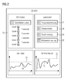
- FIG. 2 in which the current tax burden 14 and the current communication load 15 an automation device is shown on an OS client.
- SFC serial frequency division multiplexing
- the user gradually increases the control load of a Automation device of the automation device and the communication load of the automation device, wherein the user recognizes that in the context of the "gradual" startup load or Zuuress of four virtual field devices 17, 18, 19, 20 during the process control or the processing of a control program the Control load 14 is still below a control load limit 21 and the communication load 15 is still below the communication load limit 22.
Landscapes
- Engineering & Computer Science (AREA)
- Physics & Mathematics (AREA)
- General Physics & Mathematics (AREA)
- Automation & Control Theory (AREA)
- General Engineering & Computer Science (AREA)
- Geometry (AREA)
- Theoretical Computer Science (AREA)
- Quality & Reliability (AREA)
- Manufacturing & Machinery (AREA)
- Computer Hardware Design (AREA)
- Evolutionary Computation (AREA)
- Pure & Applied Mathematics (AREA)
- Mathematical Optimization (AREA)
- Mathematical Analysis (AREA)
- Computational Mathematics (AREA)
- Programmable Controllers (AREA)
- Control By Computers (AREA)
Abstract
Description
- Die Erfindung betrifft ein Verfahren zum Erweitern einer Automatisierungseinrichtung mit einem Feldgerät, wobei die Automatisierungseinrichtung zumindest ein Automatisierungsgerät und zumindest ein Feldgerät aufweist, die an eine Kommunikationsverbindung angeschlossen sind, und wobei die Automatisierungseinrichtung ferner durch ein Engineeringverfahren zur Lösung einer Automatisierungsaufgabe derart projektiert ist, dass das zumindest eine Automatisierungsgerät während einer Prozesssteuerung ein projektiertes Steuerprogramm verarbeitet, das eine Vielzahl von Steuer-Bausteinen umfasst. Darüber hinaus betrifft die Erfindung eine Automatisierungseinrichtung gemäß dem Oberbegriff des Anspruchs 3 zur Durchführung des Verfahrens.
- Aus dem Siemens-Katalog "Prozessleitsystem SIMATIC PCS 7, Ausgabe 2014/15, Kapitel 4, ist ein Engineering-System einer Automatisierungseinrichtung bekannt, das dazu ausgebildet ist, sowohl Hardware- als auch Software-Automatisierungskomponenten der Automatisierungseinrichtung zu projektieren, wobei insbesondere im Rahmen eines "Engineering der Automatisierung" ein Anwender ein Steuerprogramm zur Steuerung eines technischen Prozesses bzw. einer zu steuernden Anlage erstellt bzw. projektiert.
- Eine derartige Anlage ist gewöhnlich keine statische Produktionsstätte, die einmal geplant, errichtet und in Betrieb genommen und anschließend nicht mehr verändert wird. Vielmehr unterliegt die Anlage ständigen Änderungen und Anpassungen, um die Produktion zu optimieren und zu erweitern. Dazu ist es gewöhnlich erforderlich, auch neue prozessnahe Automatisierungskomponenten in Form von weiteren Feldgeräten in die Automatisierungseinrichtung einzubinden. Diese Einbindung erfolgt derart, dass diese Feldgeräte über einen Bus mit dem Automatisierungsgerät bzw. mit einer Steuerung der Automatisierungseinrichtung kommunikativ verbunden werden und das Steuerprogramm bzw. die Automatisierungssoftware mit entsprechenden Steuerbausteinen zum Ansteuern dieser Feldgeräte entsprechend ergänzt wird. Im Rahmen einer derartigen Erweiterung ist es wünschenswert, dass die Produktion - z. B. die Produktion zur Herstellung von Kunstharz, Farbstoffen oder Düngemitteln - nicht störend beeinflusst wird. Dies bedeutet, dass die bereits bestehenden Automatisierungskomponenten der Automatisierungseinrichtung während der Inbetriebsetzung bzw. während der Einbindung der neuen Feldgeräte ohne wesentliche Einschränkung des Produktionsbetriebs weiterlaufen muss; denn jede Einschränkung oder sogar ein Produktionsstopp (Anlagenstillstand) führt gewöhnlich zu finanziellen Einbußen.
- Ob die vorhanden Leistungsreserven des Automatisierungsgerätes oder der Kommunikationsverbindung ausreichen, um die neuen Feldgeräte ohne eine derartige Einschränkung in Betrieb setzen zu können, zeigt sich während deren Inbetriebnahme. Nicht selten führt diese Inbetriebnahme zu einem Stillstand der Anlage und damit zu einem Produktionsstopp, weil die Leistungsreserven nicht ausreichen, um Aufgaben zu vorgegebenen Verarbeitungszyklen des Automatisierungsgerätes oder im Rahmen der vorgegebenen Kommunikationszyklen des Kommunikationsnetzes der Automatisierungseinrichtung zu bewerkstelligen.
- Um die Störanfälligkeit während der Inbetriebnahme der neuen Feldgeräte zu verringern, können im Rahmen der Projektierung von Erweiterungen der Automatisierungseinrichtung die Leistungsreserven der Steuerung und des Kommunikationsnetzes abgeschätzt werden. Hier spielen neben klaren Fakten, wie die maximale Zahl der Automatisierungskomponenten bzw. Busteilnehmer und der maximale Umfang der Steuerungssoftware bezogen auf die Speicherbelegung und die Verarbeitungslaufzeit bzw. den Verarbeitungszyklus, vor allem auch die langjähre Erfahrung der Projekteure eine bedeutende Rolle. Aufgrund dieser Abschätzungen bzw. Annahmen erfolgt die Inbetriebnahme nie ohne Restrisiko. Dieses Restrisiko kann vermindert werden, indem eine entsprechende "Schatten-Anlage bzw. - Automatisierungseinrichtung" aufgebaut wird, um die Funktionsweise und die Inbetriebnahme vorab zu testen. Dies bedeutet erhebliche Material- und Personalkosten, wobei ferner eine Schatten-Anlage für die Vorbereitung der Erweiterung in der Regel auch nur eine Nachbildung der Anlage und nie eine exakte Kopie repräsentiert.
- Der Erfindung liegt daher die Aufgabe zugrunde, ein Verfahren der eingangs genannten Art anzugeben, mittels welchem die Erweiterung der Automatisierungseinrichtung vereinfacht wird. Darüber hinaus ist eine Automatisierungseinrichtung gemäß dem Oberbegriff des Anspruchs 3 zu schaffen, welches zur Durchführung des Verfahrens geeignet ist.
- Diese Aufgabe wird im Hinblick auf das Verfahren durch die im kennzeichenenden Teil des Anspruchs 1 angegebenen, bezüglich der Automatisierungseinrichtung durch die im kennzeichnenden Teil des Anspruchs 3 angegebenen Maßnahmen gelöst.
- Vorteilhaft ist, dass ein sicherer und stufenweise steigerungsfähiger "Stresstest" für die Erweiterung der Automatisierungseinrichtung möglich ist, wobei auf eine "Schatten-Automatisierungseinrichtung" verzichtet werden kann und sichergestellt ist, dass ein Stillstand der Automatisierungseinrichtung und damit ein Produktionsstopp vermieden wird. Ein Anwender kann mehrere virtuelle Feldgeräte projektieren, die jeweils ein reales Feldgerät repräsentieren sowie diese realen Feldgeräte emulieren. Diese virtuellen Feldgeräte werden nacheinander der Automatisierungseinrichtung zugeschaltet bzw. aktiviert, wobei nach jedem Zuschalten eines der virtuellen Feldgeräte zunächst die aktuelle Kommunikations-Belastung und die aktuelle Steuer-Belastung der Automatisierungseinrichtung erfasst werden. Für den Fall, dass die aktuelle Kommunikations-Belastung eine Kommunikations-Lastgrenze und die aktuelle Steuer-Belastung eine Steuer-Lastgrenze nicht überschreiten, kann der Anwender die Automatisierungseinrichtung schließlich um das reale Feldgerät erweitern, welches durch das zugeschaltete virtuelle Feldgerät emuliert wurde. Anschließend kann ein weiteres der virtuellen Feldgeräte zugeschaltet werden um wiederum zu prüfen, ob die Automatisierungseinrichtung um ein diesem virtuellen Feldgerät entsprechendes reales Feldgerät erweitert werden kann. Dem Anwender wird stets angezeigt, wie hoch die aktuelle Kommunikationsund Steuer-Belastung ist, sodass die Automatisierungseinrichtung quasi in "homöopathischen Dosen" (durch Hinzufügen jeweils eines weiteren virtuellen Feldgerätes) an die Kommunikations- und Steuer-Lastgrenzen herangeführt werden kann.
- Falls allerdings die aktuelle Kommunikations- oder die aktuelle Steuer-Belastung die jeweilige Lastgrenze überschreitet, nachdem ein virtuelles Feldgerät zugeschaltet wurde, ist eine Erweiterung der bestehenden Automatisierungseinrichtung mit dem realen Feldgerät, das durch dieses zugeschaltete virtuelle Feldgerät emuliert wurde, nicht möglich. In diesem Fall muss zunächst die bestehende Automatisierungseinrichtung mit einem oder mehreren Automatisierungsgeräten und/oder Kommunikationsmitteln erweitert werden.
- In einer Ausgestaltung der Erfindung gemäß den im Anspruch 2 angegebenen Maßnahmen wird eine Remotebearbeitung ermöglicht. Dem Anwender wird die aktuelle Kommunikationsund die aktuelle Steuer-Belastung auf einem Bedien- und Beobachtunggerät angezeigt, wobei der Anwender über dieses Gerät den Steuer-Baustein freischalten kann, falls die aktuelle Kommunikations- und die aktuelle Steuer-Belastung die jeweilige Lastgrenze nicht überschreiten.
- Anhand der Zeichnung, in der ein Ausführungsbeispiel der Erfindung veranschaulicht ist, werden im Folgenden die Erfindung, deren Ausgestaltungen sowie Vorteile näher erläutert.
- Es zeigen in einer vereinfachten Darstellung
- Figur 1
- Bestandteile einer Automatisierungseinrichtung und
- Figur 2
- die Anzeige einer Kommunikations- und Steuer-Belastung auf einem Bedien- und Beobachtungsgerät.
- In
Figur 1 ist mit 1 eine mittels eines hier nicht dargestellten Engineering-Systems projektierte Automatisierungseinrichtung 1 dargestellt. Diese umfasst im vorliegenden Ausführungsbeispiel ein Automatisierungsgerät 2, einen OS-Client bzw. ein Bedien- und Beobachtungsgerät 3 eines OS-Operator-Systems, das ferner einen hier nicht dargestellten OS-Server aufweist, eine dezentrale Peripherie 4 sowie einen Kommunikationsteilnehmer 5. Das Automatisierungsgerät 2 kommuniziert mit dem OS-Client 3 über eine Kommunikationsverbindung 6 und über eine weitere Kommunikationsverbindung 7 mit der dezentralen Peripherie 4 und einem Kommunikationsteilnehmer 5, wobei die Kommunikationsverbindungen 6, 7 als Busverbindungen ausgebildet sind. Eine Vielzahl von Feldgeräten 9 (Aktoren, Sensoren) ist an den Bus 7 und/oder an einen weiteren mit der dezentralen Peripherie 4 verbundenen Bus 8 angeschlossen, wobei während der Prozesssteuerung, d. h. während des Run-Betriebs des Automatisierungsgerätes 2, die Feldgeräte 9 mittels Steuer-Bausteinen angesteuert werden. Diese Steuer-Bausteine sind Bestandteil eines Steuerprogramms, welches nach Maßgabe einer zu lösenden Automatisierungsaufgabe während eines Engineerings durch ein Engineeringverfahren projektiert bzw. erstellt wird. - Ein an sich bekanntes Engineering bzw. Engineeringverfahren zur Erstellung eines Steuerprogramms basiert auf einem auf dem Engineering-System ablauffähigen Continuous Function Chart (CFC)- und auf Sequential Continuous Function Chart (SFC)-Editoren.
- Ein Anwender erstellt mittels des CFC-Editors aus vorgefertigten Bausteinen nach Maßgabe der zu lösenden Automatisierungsaufgabe grafisch das Steuerprogramm für das Automatisierungsgerät 2 und wählt dazu die Bausteine, z. B. einen Regler- oder Zähler-Baustein, aus einem verfügbaren Bausteinvorrat aus, platziert die Bausteine z. B. per Drag&Drop in einem Funktionsplan (z. B. CFC-Plan) und verschaltet diese per Mausklick miteinander. Nachdem der Anwender alle Funktionen im Funktionsplan erstellt hat, erzeugt das Engineering-System durch das Automatisierungsgerät 2 lesbare CFC-Funktionen, die in dieses Automatisierungsgerät 2 geladen und dort im Rahmen der Prozesssteuerung zur Lösung der Automatisierungsaufgabe verarbeitet werden.
- Mittels des SFC-Editors erstellt der Anwender ferner in gewohnter Art und Weise grafisch eine Ablaufsteuerung (SCF), die gewöhnlich eine Vielzahl von Schrittketten umfasst, die wiederum eine Vielzahl von Rezeptelementen sowie Transitionen aufweisen, z. B. Rezeptelemente in Form von Rezeptoperationen oder Rezeptfunktionen, z. B. Dosieren, Heizen oder Rühren. Aus dieser Ablaufsteuerung erzeugt das Engineering-System durch das Automatisierungsgerät 2 verarbeitbare (SFC-) Objekte, die das Engineering-System compiliert und in das Automatisierungsgerät 2 lädt.
- Während der Prozesssteuerung - also im RUN-Betrieb des Automatisierungsgeräts 2 - wird die Interaktion und Verknüpfung zwischen den (SFC-) Objekten und den CFC-Funktionen über Prozesswerte und Steuersignale (SFC-Daten) bewerkstelligt, wobei ferner einem Operator die Schrittkette auf dem OS-Client 3 dargestellt wird. Dadurch kann der Operator beobachten, welches Rezeptelement der Schrittketten gerade verarbeitet wird. Jedem Schritt der Schrittkette ist eine bestimmte Aktion zugeordnet, welche die CFC-Funktionen parametrieren und aktivieren, wobei dazu entsprechende Steuersignale gesetzt werden. Die Prozesswerte umfassen Prozesseingangswerte (Istwerte), welche Sensoren dem Automatisierungsgerät 2 zuführen und die das Automatisierungsgerät 2 dem OS-Server zur Hinterlegung in einem Prozessabbild übermittelt, sowie Prozessausgangswerte (Sollwerte), die der OS-Server dem Automatisierungsgerät 2 zur Ansteuerung der Aktoren zuführt.
- Im vorliegenden Ausführungsbeispiel wird angenommen, dass im Automatisierungsgerät 2 ein projektiertes Steuerprogramm 10 (SFCs, CFCs) hinterlegt ist und das Automatisierungsgerät 2 dieses Steuerprogramm 10 zur Prozesssteuerung gerade verarbeitet. Um während dieser Prozesssteuerung die Automatisierungseinrichtung 1 um ein oder mehrere reale Feldgeräte 9r - ohne störende Einflüsse auf die Prozesssteuerung - erweitern zu können, sind im Kommunikationsteilnehmer 5 für jedes dieser Feldgeräte 9r ein durch das Engineering-System projektiertes virtuelles Feldgerät 5v und ferner im Automatisierungsgerät 2 ein Erweiterungs-Baustein 11 hinterlegt, welcher für jedes virtuelle Feldgerät 5v einen projektierten Steuer-Baustein 10s zum Ansteuern des jeweiligen virtuellen Feldgerätes 5v aufweist. Diese virtuellen Feldgeräte 5v repräsentieren die realen Feldgeräte und sind dazu ausgebildet, die realen Feldgeräte zu emulieren. Der Erweiterungs-Baustein 11 ist ferner mit einer OS-Schnittstelle 12 zum Austauschen von Informationen zwischen dem Erweiterungs-Baustein 11 und dem OS-Client 3 versehen, wobei einerseits der Anwender durch eine entsprechende Eingabe am OS-Client 3 die Erweiterung der Automatisierungseinrichtung 1 einleiten kann und andererseits der OS-Client 3 dem Anwender die aktuelle Kommunikations- und Steuer-Belastung anzeigt. Darüber hinaus kann der Anwender durch eine weitere Eingabe am OS-Client 3 die jeweiligen Steuer-Bausteine 10s freischalten, damit der Erweiterungs-Baustein 11 in Abhängigkeit der aktuellen Kommunikations- und Steuer-Belastung die jeweiligen Steuer-Bausteine 10s in das Steuerprogramm 10 einbindet.
- Die Erweiterung der Automatisierungseinrichtung 1 erfolgt in der Art und Weise, dass ein Anwender zunächst eines der projektierten virtuellen Feldgeräte 5v auswählt, indem er z. B. ein diesem Feldgerät 5v zugeordnetes und auf dem OS-Client 3 dargestelltes Icon anwählt bzw. markiert. Aufgrund dieser Auswahl kommuniziert ein Ausführungsteil 13 des Erweiterungs-Bausteins 11 mit diesem virtuellen, im Kommunikationsteilnehmer 5 hinterlegten Feldgerät 5v, wobei der Kommunikationsteilnehmer 5 die aktuelle Kommunikations-Belastung ermittelt und abspeichert. Diese Kommunikations-Belastung umfasst die durch die Kommunikation zwischen dem virtuellen Feldgerät 5v und dem Ausführungsteil 13 und die durch die Kommunikation der Prozesssteuerung verursachte Belastung. Unter der Formulierung "durch die Kommunikation der Prozesssteuerung verursachte Belastung" wird die Belastung der Kommunikationsverbindung 7 während der Verarbeitung des Steuerprogramms 10 verstanden, während dessen das Automatisierungsgerät 2 mit den realen Feldgeräten 9 kommuniziert. Dadurch, dass der Kommunikationsteilnehmer 5 die Kommunikations-Belastung erfasst, wird das Automatisierungsgerät 2 nicht zusätzlich belastet. Der Erweiterungs-Baustein 11 liest die im Kommunikationsteilnehmer 5 abgespeicherte aktuelle Kommunikations-Belastung aus und übermittelt diese über die OS-Schnittstelle 12 dem OS-Client 3, welcher die aktuelle Kommunikations-Belastung dem Anwender anzeigt. Für den Fall, dass diese aktuelle Kommunikations-Belastung eine vorgegebene Kommunikations-Lastgrenze erreicht oder überschreitet, wird der Anwender mittels einer Anzeige bzw. Meldung auf dem OS-Client darauf hingewiesen, dass eine Erweiterung der bestehenden Automatisierungseinrichtung 1 mit dem dem virtuellen Feldgerät 5v entsprechenden realen Feldgerät 9r nicht möglich ist, es sei denn, die Automatisierungseinrichtung 1 wird um ein weiteres Kommunikationsmittel (Busverbindungen, Switches, ... ) erweitert.
- Für den Fall dagegen, dass diese aktuelle Kommunikations-Belastung die vorgegebene Kommunikations-Lastgrenze nicht überschreitet, aktiviert der Ausführungsteil 13 automatisch den Steuer-Baustein 10s zum Ansteuern des ausgewählten virtuellen Feldgerätes 5v. Während dieser Ansteuerung erfasst der Erweiterungs-Bausteins 11 die Steuer-Belastung des Automatisierungsgerätes 2, welche die durch die Prozesssteuerung und die durch die Verarbeitung des Steuer-Bausteins 10s zum Ansteuern des ausgewählten virtuellen Feldgerätes 5v verursachte Belastung umfasst, wobei diese beiden Belastungen sich auf den Verarbeitungszyklus des Automatisierungsgerätes 2 auswirken. Dabei wird unter der Formulierung "die durch die Prozesssteuerung verursachte Belastung" die Belastung des Automatisierungsgerätes 2 während der Verarbeitung des Steuerprogramms 10 verstanden. Zur Anzeige der aktuellen Steuer-Belastung übermittelt der Erweiterungs-Baustein 11 die aktuelle Steuer-Belastung ebenfalls über die OS-Schnittstelle 12 dem OS-Client 3, wodurch dem Anwender neben der aktuellen Kommunikations-Belastung auch die aktuelle Steuer-Belastung der Automatisierungseinrichtung 1 angezeigt wird. Für den Fall, dass diese aktuelle Steuer-Belastung eine vorgegebene Steuer-Lastgrenze nicht erreicht oder überschreitet, bindet der Erweiterungs-Baustein 11 den Steuer-Baustein 10s in das Steuerprogramm 10 ein, falls der Anwender diesen Steuer-Baustein 10s zum Anschließen des realen Feldgerätes 9r an den Bus freischaltet. Die Freischaltung durch den Anwender erfolgt mittels einer geeigneten Eingabe am OS-Client 3, auf welchem dem Anwender neben der aktuellen Steuer-Belastung die Steuer-Lastgrenze angezeigt wird. Nachdem der Anwender den Steuer-Baustein 10s freigeschaltet hat, kann das dem virtuellen Feldgerät 5v entsprechende reale Feldgerät 9r an den Bus 8 angeschlossen werden. Für den Fall, dass die aktuelle Steuer-Belastung allerdings die vorgegebene Steuer-Lastgrenze erreicht oder überschreitet, blockiert der Erweiterungs-Baustein 11 den Steuer-Baustein 10s, was bedeutet, dass dieser nicht in das Steuerprogramm 10 eingebunden wird. Auch in diesem Fall wird dem Anwender angezeigt, dass die bestehende Automatisierungseinrichtung 1 um dieses Feldgerät nicht erweitert werden kann. Eine Erweiterung der Automatisierungseinrichtung ist nur dann möglich, wenn diese um ein weiteres Automatisierungsgerät erweitert wird, wodurch die Steuer-Belastung auf mehrere Automatisierungsgeräte verteilt werden kann.
- In der beschrieben Art und Weise kann die Automatisierungseinrichtung 1 um weitere Feldgeräte erweitert werden. Dazu wird zunächst ein weiteres der virtuellen Feldgeräte zugeschaltet und wiederum geprüft, ob die Automatisierungseinrichtung 1 um ein weiteres diesem virtuellen Feldgerät entsprechendes reales Feldgerät erweitert werden kann. Dem Anwender wird dazu stets angezeigt, wie die aktuelle Kommunikations- und Steuer-Belastung ist, sodass die Automatisierungseinrichtung 1 quasi in "homöopathischen Dosen" an die Kommunikations-und Steuer-Lastgrenzen herangeführt werden kann.
- Im Folgenden wird auf
Figur 2 verwiesen, in welcher die aktuelle Steuer-Belastung 14 sowie die aktuelle Kommunikations-Belastung 15 einer Automatisierungseinrichtung auf einem OS-Client dargestellt ist. Mittels den jeweiligen durch den Anwender aktivierbaren Schritten einer (SFC-)Schrittkette 16 erhöht der Anwender stufenweise die Steuer-Belastung eines Automatisierungsgerätes der Automatisierungseinrichtung sowie die Kommunikations-Belastung der Automatisierungseinrichtung, wobei der Anwender erkennt, dass im Rahmen des "stufenweisen" Hochfahrens der Last bzw. Zuschaltens von vier virtuellen Feldgeräten 17, 18, 19, 20 während der Prozesssteuerung bzw. der Verarbeitung eines Steuerprogramms die Steuer-Belastung 14 immer noch unterhalb einer Steuer-Lastgrenze 21 und die Kommunikations-Belastung 15 immer noch unterhalb der Kommunikations-Lastgrenze 22 liegt. Dies bedeutet, dass an die Automatisierungseinrichtung vier reale Feldgeräte, die durch die vier virtuellen Feldgeräte emuliert wurden, angeschlossen werden kann, ohne dass die Automatisierungseinrichtung um ein weiteres Automatisierungsgerät und weitere Kommunikationsmittel erweitert werden muss.
Claims (4)
- Verfahren zum Erweitern einer Automatisierungseinrichtung (1) mit mindestens einem Feldgerät (9), wobei die Automatisierungseinrichtung (1)- zumindest ein Automatisierungsgerät (2) und zumindest ein Feldgerät (9) aufweist, die an eine Kommunikationsverbindung (7, 8) angeschlossen sind, und- durch ein Engineeringverfahren zur Lösung einer Automatisierungsaufgabe derart projektiert ist, dass das zumindest eine Automatisierungsgerät (2) während einer Prozesssteuerung ein projektiertes Steuerprogramm (10) verarbeitet, das eine Vielzahl von Steuer-Bausteinen umfasst,
dadurch gekennzeichnet, dass- mindestens ein ein reales Feldgerät (9r) repräsentierendes virtuelles Feldgerät (5v) und ein Steuer-Baustein (10s) zum Ansteuern des virtuellen Feldgeräts (5v) projektiert werden,- die aktuelle Kommunikations-Belastung ermittelt wird, welche die durch die Kommunikation der Prozesssteuerung und die durch die Kommunikation zwischen dem virtuellen Feldgerät (5v) und einem projektierten Erweiterungs-Baustein (11) des zumindest einen Automatisierungsgeräts (2) verursachte Belastung umfasst,- die aktuelle Steuer-Belastung des zumindest einen Automatisierungsgeräts (2) erfasst wird, welche die durch die Prozesssteuerung und die durch die Verarbeitung des projektierten Steuer-Bausteins (10s) verursachte Belastung umfasst, und- in Abhängigkeit der aktuellen Kommunikations- und der aktuellen Steuer-Belastung der projektierte Steuer-Baustein (10s) in das Steuerprogramm (10) eingebunden wird, falls dieser Steuer-Baustein (10s) zum Anschließen des realen Feldgerätes (9r) an den Bus (7, 8) durch einen Anwender freigeschaltet wird. - Verfahren nach Anspruch 1, dadurch gekennzeichnet, dass einem Anwender die aktuelle Kommunikations- und Steuer-Belastung auf einem Bedien- und Beobachtunggerät (3) angezeigt und über dieses Gerät (3) der Steuer-Baustein freigeschaltet wird.
- Automatisierungseinrichtung, welche- zumindest ein Automatisierungsgerät (2) und zumindest ein Feldgerät (9) aufweist, die an eine Kommunikationsverbindung (7, 8) angeschlossen sind,- durch ein Engineeringverfahren zur Lösung einer Automatisierungsaufgabe derart projektiert ist, dass das zumindest eine Automatisierungsgerät (2) während einer Prozesssteuerung ein projektiertes Steuerprogramm (10) verarbeitet, das eine Vielzahl von Steuer-Bausteinen umfasst,
dadurch gekennzeichnet, dass- in einem an die Kommunikationsverbindung (7, 8) angeschlossenen projektierten Kommunikationsteilnehmer (5) mindestens ein projektiertes virtuelles Feldgerät (5v) hinterlegt ist, das ein reales Feldgerät (9r) repräsentiert,- der Kommunikationsteilnehmer (5) die aktuelle Kommunikations-Belastung ermittelt, welche die durch die Kommunikation der Prozesssteuerung und die durch die Kommunikation zwischen dem virtuellen Feldgerät (5v) und einem projektierten Erweiterungs-Baustein (11) des zumindest einen Automatisierungsgeräts (2) verursachte Belastung umfasst,- ein projektierter Steuer-Baustein (10s) zum Ansteuern des virtuellen Feldgeräts (5v) im Erweiterungs-Baustein (11) hinterlegt ist,- der Erweiterungs-Baustein (11) die aktuelle Steuer-Belastung des zumindest einen Automatisierungsgeräts (2) erfasst, welche die durch die Prozesssteuerung und die durch die Verarbeitung des Steuer-Bausteins (10s) verursachte Belastung umfasst, und- der Erweiterungs-Baustein (11) dazu ausgebildet ist, in Abhängigkeit der aktuellen Kommunikations- und der aktuellen Steuer-Belastung den projektierten Steuer-Baustein (10s) in das Steuerprogramm (10) einzubinden, falls ein Anwender diesen Steuer-Baustein (10s) zum Anschließen des realen Feldgerätes (9r) an den Bus (7, 8) freischaltet. - Automatisierungseinrichtung nach Anspruch 3, dadurch gekennzeichnet, dass die Automatisierungseinrichtung (1) mit einem Bedien- und Beobachtunggerät (3) versehen ist- zum Anzeigen der aktuellen Kommunikations- und Steuer-Belastung und- zum Freischalten des Steuer-Bausteins (10s).
Priority Applications (3)
| Application Number | Priority Date | Filing Date | Title |
|---|---|---|---|
| EP15163409.4A EP3082001B1 (de) | 2015-04-13 | 2015-04-13 | Verfahren zum erweitern einer automatisierungseinrichtung mittels einem virtuellen feldgerät sowie automatisierungseinrichtung |
| US15/093,000 US9886028B2 (en) | 2015-04-13 | 2016-04-07 | Automation facility and method for expanding the automation facility with at least one field device |
| CN201610224048.XA CN106054762B (zh) | 2015-04-13 | 2016-04-12 | 用于扩展自动化装置的方法以及自动化装置 |
Applications Claiming Priority (1)
| Application Number | Priority Date | Filing Date | Title |
|---|---|---|---|
| EP15163409.4A EP3082001B1 (de) | 2015-04-13 | 2015-04-13 | Verfahren zum erweitern einer automatisierungseinrichtung mittels einem virtuellen feldgerät sowie automatisierungseinrichtung |
Publications (2)
| Publication Number | Publication Date |
|---|---|
| EP3082001A1 true EP3082001A1 (de) | 2016-10-19 |
| EP3082001B1 EP3082001B1 (de) | 2020-09-09 |
Family
ID=53002501
Family Applications (1)
| Application Number | Title | Priority Date | Filing Date |
|---|---|---|---|
| EP15163409.4A Active EP3082001B1 (de) | 2015-04-13 | 2015-04-13 | Verfahren zum erweitern einer automatisierungseinrichtung mittels einem virtuellen feldgerät sowie automatisierungseinrichtung |
Country Status (3)
| Country | Link |
|---|---|
| US (1) | US9886028B2 (de) |
| EP (1) | EP3082001B1 (de) |
| CN (1) | CN106054762B (de) |
Cited By (2)
| Publication number | Priority date | Publication date | Assignee | Title |
|---|---|---|---|---|
| WO2020200870A1 (de) * | 2019-03-29 | 2020-10-08 | Siemens Aktiengesellschaft | Verfahren zum engineering und simulation eines automatisierungssystems mittels digitaler zwillinge |
| DE102022105472A1 (de) | 2022-03-09 | 2023-09-14 | Endress+Hauser SE+Co. KG | System der Automatisierungstechnik |
Families Citing this family (1)
| Publication number | Priority date | Publication date | Assignee | Title |
|---|---|---|---|---|
| US10934764B2 (en) * | 2016-09-08 | 2021-03-02 | Magna Closures Inc. | Radar detection system for non-contact human activation of powered closure member |
Citations (4)
| Publication number | Priority date | Publication date | Assignee | Title |
|---|---|---|---|---|
| DE10245176A1 (de) * | 2002-09-26 | 2004-04-01 | Endress + Hauser Process Solutions Ag | Verfahren zur Simulation eines Feldgerätes in einem Netzwerk der Prozessautomatisierungstechnik |
| DE102007062395A1 (de) * | 2007-12-20 | 2009-06-25 | Endress + Hauser Flowtec Ag | Verfahren zum Parametrieren eines Feldgerätes der Prozessautomatisierungstechnik |
| DE102010029952A1 (de) * | 2010-06-10 | 2011-12-15 | Endress + Hauser Process Solutions Ag | Verfahren zum Integrieren von zumindest einem Feldgerät in ein Netzwerk der Automatisierungstechnik |
| DE102010053485A1 (de) * | 2010-12-04 | 2012-06-06 | Robert Bosch Gmbh | Verfahren zum Betreiben einer Arbeitsmaschine und Arbeitsmaschine mit virtueller Automatisierung |
Family Cites Families (5)
| Publication number | Priority date | Publication date | Assignee | Title |
|---|---|---|---|---|
| DE102004039886A1 (de) * | 2004-08-17 | 2006-03-09 | Endress + Hauser Flowtec Ag | Verfahren zum Betreiben eines Feldgerätes der Automatisierungstechnik |
| US20070078696A1 (en) * | 2005-08-30 | 2007-04-05 | Invensys Systems Inc. | Integrating high level enterprise-level decision- making into real-time process control |
| DE102006059819A1 (de) * | 2006-12-11 | 2008-06-19 | Index-Werke Gmbh & Co. Kg Hahn & Tessky | Arbeitsmaschine |
| DE112011103241T5 (de) * | 2010-09-27 | 2013-08-14 | Fisher-Rosemount Systems, Inc. | Verfahren und Vorrichtung zum Virtualisieren eines Prozesssteuerungssystems |
| CN103793278B (zh) * | 2013-09-30 | 2017-04-26 | 中国电子设备系统工程公司研究所 | 一种基于虚拟器件运维规则的资源自动调整方法 |
-
2015
- 2015-04-13 EP EP15163409.4A patent/EP3082001B1/de active Active
-
2016
- 2016-04-07 US US15/093,000 patent/US9886028B2/en active Active
- 2016-04-12 CN CN201610224048.XA patent/CN106054762B/zh active Active
Patent Citations (4)
| Publication number | Priority date | Publication date | Assignee | Title |
|---|---|---|---|---|
| DE10245176A1 (de) * | 2002-09-26 | 2004-04-01 | Endress + Hauser Process Solutions Ag | Verfahren zur Simulation eines Feldgerätes in einem Netzwerk der Prozessautomatisierungstechnik |
| DE102007062395A1 (de) * | 2007-12-20 | 2009-06-25 | Endress + Hauser Flowtec Ag | Verfahren zum Parametrieren eines Feldgerätes der Prozessautomatisierungstechnik |
| DE102010029952A1 (de) * | 2010-06-10 | 2011-12-15 | Endress + Hauser Process Solutions Ag | Verfahren zum Integrieren von zumindest einem Feldgerät in ein Netzwerk der Automatisierungstechnik |
| DE102010053485A1 (de) * | 2010-12-04 | 2012-06-06 | Robert Bosch Gmbh | Verfahren zum Betreiben einer Arbeitsmaschine und Arbeitsmaschine mit virtueller Automatisierung |
Non-Patent Citations (1)
| Title |
|---|
| "Prozessleitsystem SIMATIC PCS 7", 2014 |
Cited By (2)
| Publication number | Priority date | Publication date | Assignee | Title |
|---|---|---|---|---|
| WO2020200870A1 (de) * | 2019-03-29 | 2020-10-08 | Siemens Aktiengesellschaft | Verfahren zum engineering und simulation eines automatisierungssystems mittels digitaler zwillinge |
| DE102022105472A1 (de) | 2022-03-09 | 2023-09-14 | Endress+Hauser SE+Co. KG | System der Automatisierungstechnik |
Also Published As
| Publication number | Publication date |
|---|---|
| CN106054762B (zh) | 2018-11-13 |
| US9886028B2 (en) | 2018-02-06 |
| EP3082001B1 (de) | 2020-09-09 |
| US20170023932A1 (en) | 2017-01-26 |
| CN106054762A (zh) | 2016-10-26 |
Similar Documents
| Publication | Publication Date | Title |
|---|---|---|
| EP2806319B1 (de) | Konfigurationssoftware und Verfahren zum Erstellen von Konfigurationsdaten und eines PLC-Programms für ein eine speicherprogrammierbare Steuerung umfassendes Steuer- und/oder Schutzgerät für die Mittel- oder Hochspannungstechnik | |
| EP2453326B1 (de) | Verfahren und System zur Bedienung einer Maschine aus der Automatisierungstechnik | |
| DE102013100465A1 (de) | Mikroprozessor-gesteuerte Steuerungseinrichtung für eine Spritzgiessanlage | |
| EP2098926A1 (de) | Verfahren und Vorrichtung zum Programmieren und/oder Konfigurieren einer Sicherheitssteuerung | |
| EP2098925A1 (de) | Verfahren und Vorrichtung zum Programmieren und/oder Konfigurieren einer Sicherheitssteuerung | |
| EP3082001B1 (de) | Verfahren zum erweitern einer automatisierungseinrichtung mittels einem virtuellen feldgerät sowie automatisierungseinrichtung | |
| EP3067768B1 (de) | Automatisierungseinrichtung und Operator-System | |
| DE102012205709A1 (de) | Verfahren zum Betreiben eines elektrischen Antriebssystems und Antriebssystem | |
| EP2876778B1 (de) | Elektrische Anlage mit einer unterbrechungsfreien Stromversorgungseinheit | |
| WO2014161986A1 (de) | Steuer- und datenübertragungsanlage zur redundanten prozesssteuerung und verfahren zur firmware-aktualisierung | |
| DE102016123599A1 (de) | Robotersteuerung mit Funktion zur Kommunikation mit einer speicherprogrammierbaren Steuerung und Kommunikationssystem | |
| DE10117459A1 (de) | Verfahren und Vorrichtung zur Gewinnung von Diagnoseinformationen | |
| WO2000051095A2 (de) | Verfahren zum einrichten einer steuervorrichtung eines programmgesteuerten haushaltgeräts sowie steuervorrichtung zur durchführung des verfahrens | |
| EP3457234A1 (de) | Verfahren und datenverarbeitungsvorrichtung zum computerunterstützten bereitstellen einer in form von computercode vorliegenden information zu einem prozessmodul, sowie computerprogrammprodukt zur durchführung des verfahrens | |
| EP3582032B1 (de) | Feldgerät mit reduzierter stillstandszeit bei firmware-update | |
| DE102014217561B4 (de) | Verfahren und Anordnung zum Test eines Multimediagerätes | |
| AT14003U1 (de) | Verfahren zum Sichern von für den Betrieb einer Formgebungsmaschine notwendigen Dateien | |
| DE10017708B4 (de) | Verfahren zum Steuern von Mechanismen und technischen Systemen, Einrichtung und Steuerungssoftware | |
| EP1947536B1 (de) | Verfahren zur Konfigurationsänderung eines laufenden Automatisierungsgerätes | |
| EP2811349A1 (de) | Verfahren zum Betreiben eines Automatisierungssystems | |
| DE102006056143A1 (de) | Verfahren zur Synchronisation von Steuerrezepten | |
| DE4210844C2 (de) | Programmierbare Steuerung und Verfahren zur Überwachung eines Ablaufprogrammes für eine programmierbare Steuerung | |
| WO2013020844A1 (de) | Steuerungs- und/oder regelungseinrichtung | |
| EP3948449B1 (de) | Verfahren und engineering-system zur änderung eines programms einer industriellen automatisierungskomponente | |
| BE1026752B1 (de) | Vorrichtung und Verfahren zur iterativen und interaktiven Projektierung von einer I/O-Station für eine automatisierungstechnische Steuerung |
Legal Events
| Date | Code | Title | Description |
|---|---|---|---|
| PUAI | Public reference made under article 153(3) epc to a published international application that has entered the european phase |
Free format text: ORIGINAL CODE: 0009012 |
|
| AK | Designated contracting states |
Kind code of ref document: A1 Designated state(s): AL AT BE BG CH CY CZ DE DK EE ES FI FR GB GR HR HU IE IS IT LI LT LU LV MC MK MT NL NO PL PT RO RS SE SI SK SM TR |
|
| AX | Request for extension of the european patent |
Extension state: BA ME |
|
| STAA | Information on the status of an ep patent application or granted ep patent |
Free format text: STATUS: REQUEST FOR EXAMINATION WAS MADE |
|
| 17P | Request for examination filed |
Effective date: 20170418 |
|
| RBV | Designated contracting states (corrected) |
Designated state(s): AL AT BE BG CH CY CZ DE DK EE ES FI FR GB GR HR HU IE IS IT LI LT LU LV MC MK MT NL NO PL PT RO RS SE SI SK SM TR |
|
| RAP1 | Party data changed (applicant data changed or rights of an application transferred) |
Owner name: SIEMENS AKTIENGESELLSCHAFT |
|
| STAA | Information on the status of an ep patent application or granted ep patent |
Free format text: STATUS: EXAMINATION IS IN PROGRESS |
|
| 17Q | First examination report despatched |
Effective date: 20180420 |
|
| REG | Reference to a national code |
Ref country code: DE Ref legal event code: R079 Ref document number: 502015013408 Country of ref document: DE Free format text: PREVIOUS MAIN CLASS: G05B0019042000 Ipc: H04L0012260000 |
|
| GRAP | Despatch of communication of intention to grant a patent |
Free format text: ORIGINAL CODE: EPIDOSNIGR1 |
|
| STAA | Information on the status of an ep patent application or granted ep patent |
Free format text: STATUS: GRANT OF PATENT IS INTENDED |
|
| RIC1 | Information provided on ipc code assigned before grant |
Ipc: H04L 12/26 20060101AFI20200603BHEP |
|
| INTG | Intention to grant announced |
Effective date: 20200618 |
|
| GRAS | Grant fee paid |
Free format text: ORIGINAL CODE: EPIDOSNIGR3 |
|
| GRAA | (expected) grant |
Free format text: ORIGINAL CODE: 0009210 |
|
| STAA | Information on the status of an ep patent application or granted ep patent |
Free format text: STATUS: THE PATENT HAS BEEN GRANTED |
|
| AK | Designated contracting states |
Kind code of ref document: B1 Designated state(s): AL AT BE BG CH CY CZ DE DK EE ES FI FR GB GR HR HU IE IS IT LI LT LU LV MC MK MT NL NO PL PT RO RS SE SI SK SM TR |
|
| REG | Reference to a national code |
Ref country code: GB Ref legal event code: FG4D Free format text: NOT ENGLISH |
|
| REG | Reference to a national code |
Ref country code: AT Ref legal event code: REF Ref document number: 1312925 Country of ref document: AT Kind code of ref document: T Effective date: 20200915 Ref country code: CH Ref legal event code: EP |
|
| REG | Reference to a national code |
Ref country code: DE Ref legal event code: R096 Ref document number: 502015013408 Country of ref document: DE |
|
| REG | Reference to a national code |
Ref country code: IE Ref legal event code: FG4D Free format text: LANGUAGE OF EP DOCUMENT: GERMAN |
|
| REG | Reference to a national code |
Ref country code: LT Ref legal event code: MG4D |
|
| PG25 | Lapsed in a contracting state [announced via postgrant information from national office to epo] |
Ref country code: LT Free format text: LAPSE BECAUSE OF FAILURE TO SUBMIT A TRANSLATION OF THE DESCRIPTION OR TO PAY THE FEE WITHIN THE PRESCRIBED TIME-LIMIT Effective date: 20200909 Ref country code: HR Free format text: LAPSE BECAUSE OF FAILURE TO SUBMIT A TRANSLATION OF THE DESCRIPTION OR TO PAY THE FEE WITHIN THE PRESCRIBED TIME-LIMIT Effective date: 20200909 Ref country code: GR Free format text: LAPSE BECAUSE OF FAILURE TO SUBMIT A TRANSLATION OF THE DESCRIPTION OR TO PAY THE FEE WITHIN THE PRESCRIBED TIME-LIMIT Effective date: 20201210 Ref country code: BG Free format text: LAPSE BECAUSE OF FAILURE TO SUBMIT A TRANSLATION OF THE DESCRIPTION OR TO PAY THE FEE WITHIN THE PRESCRIBED TIME-LIMIT Effective date: 20201209 Ref country code: NO Free format text: LAPSE BECAUSE OF FAILURE TO SUBMIT A TRANSLATION OF THE DESCRIPTION OR TO PAY THE FEE WITHIN THE PRESCRIBED TIME-LIMIT Effective date: 20201209 Ref country code: SE Free format text: LAPSE BECAUSE OF FAILURE TO SUBMIT A TRANSLATION OF THE DESCRIPTION OR TO PAY THE FEE WITHIN THE PRESCRIBED TIME-LIMIT Effective date: 20200909 Ref country code: FI Free format text: LAPSE BECAUSE OF FAILURE TO SUBMIT A TRANSLATION OF THE DESCRIPTION OR TO PAY THE FEE WITHIN THE PRESCRIBED TIME-LIMIT Effective date: 20200909 |
|
| REG | Reference to a national code |
Ref country code: NL Ref legal event code: MP Effective date: 20200909 |
|
| PG25 | Lapsed in a contracting state [announced via postgrant information from national office to epo] |
Ref country code: PL Free format text: LAPSE BECAUSE OF FAILURE TO SUBMIT A TRANSLATION OF THE DESCRIPTION OR TO PAY THE FEE WITHIN THE PRESCRIBED TIME-LIMIT Effective date: 20200909 Ref country code: LV Free format text: LAPSE BECAUSE OF FAILURE TO SUBMIT A TRANSLATION OF THE DESCRIPTION OR TO PAY THE FEE WITHIN THE PRESCRIBED TIME-LIMIT Effective date: 20200909 Ref country code: RS Free format text: LAPSE BECAUSE OF FAILURE TO SUBMIT A TRANSLATION OF THE DESCRIPTION OR TO PAY THE FEE WITHIN THE PRESCRIBED TIME-LIMIT Effective date: 20200909 |
|
| PG25 | Lapsed in a contracting state [announced via postgrant information from national office to epo] |
Ref country code: CZ Free format text: LAPSE BECAUSE OF FAILURE TO SUBMIT A TRANSLATION OF THE DESCRIPTION OR TO PAY THE FEE WITHIN THE PRESCRIBED TIME-LIMIT Effective date: 20200909 Ref country code: RO Free format text: LAPSE BECAUSE OF FAILURE TO SUBMIT A TRANSLATION OF THE DESCRIPTION OR TO PAY THE FEE WITHIN THE PRESCRIBED TIME-LIMIT Effective date: 20200909 Ref country code: SM Free format text: LAPSE BECAUSE OF FAILURE TO SUBMIT A TRANSLATION OF THE DESCRIPTION OR TO PAY THE FEE WITHIN THE PRESCRIBED TIME-LIMIT Effective date: 20200909 Ref country code: EE Free format text: LAPSE BECAUSE OF FAILURE TO SUBMIT A TRANSLATION OF THE DESCRIPTION OR TO PAY THE FEE WITHIN THE PRESCRIBED TIME-LIMIT Effective date: 20200909 Ref country code: PT Free format text: LAPSE BECAUSE OF FAILURE TO SUBMIT A TRANSLATION OF THE DESCRIPTION OR TO PAY THE FEE WITHIN THE PRESCRIBED TIME-LIMIT Effective date: 20210111 Ref country code: NL Free format text: LAPSE BECAUSE OF FAILURE TO SUBMIT A TRANSLATION OF THE DESCRIPTION OR TO PAY THE FEE WITHIN THE PRESCRIBED TIME-LIMIT Effective date: 20200909 |
|
| PG25 | Lapsed in a contracting state [announced via postgrant information from national office to epo] |
Ref country code: ES Free format text: LAPSE BECAUSE OF FAILURE TO SUBMIT A TRANSLATION OF THE DESCRIPTION OR TO PAY THE FEE WITHIN THE PRESCRIBED TIME-LIMIT Effective date: 20200909 Ref country code: AL Free format text: LAPSE BECAUSE OF FAILURE TO SUBMIT A TRANSLATION OF THE DESCRIPTION OR TO PAY THE FEE WITHIN THE PRESCRIBED TIME-LIMIT Effective date: 20200909 Ref country code: IS Free format text: LAPSE BECAUSE OF FAILURE TO SUBMIT A TRANSLATION OF THE DESCRIPTION OR TO PAY THE FEE WITHIN THE PRESCRIBED TIME-LIMIT Effective date: 20210109 |
|
| REG | Reference to a national code |
Ref country code: DE Ref legal event code: R097 Ref document number: 502015013408 Country of ref document: DE |
|
| PG25 | Lapsed in a contracting state [announced via postgrant information from national office to epo] |
Ref country code: SK Free format text: LAPSE BECAUSE OF FAILURE TO SUBMIT A TRANSLATION OF THE DESCRIPTION OR TO PAY THE FEE WITHIN THE PRESCRIBED TIME-LIMIT Effective date: 20200909 |
|
| PLBE | No opposition filed within time limit |
Free format text: ORIGINAL CODE: 0009261 |
|
| STAA | Information on the status of an ep patent application or granted ep patent |
Free format text: STATUS: NO OPPOSITION FILED WITHIN TIME LIMIT |
|
| 26N | No opposition filed |
Effective date: 20210610 |
|
| PG25 | Lapsed in a contracting state [announced via postgrant information from national office to epo] |
Ref country code: DK Free format text: LAPSE BECAUSE OF FAILURE TO SUBMIT A TRANSLATION OF THE DESCRIPTION OR TO PAY THE FEE WITHIN THE PRESCRIBED TIME-LIMIT Effective date: 20200909 Ref country code: SI Free format text: LAPSE BECAUSE OF FAILURE TO SUBMIT A TRANSLATION OF THE DESCRIPTION OR TO PAY THE FEE WITHIN THE PRESCRIBED TIME-LIMIT Effective date: 20200909 |
|
| REG | Reference to a national code |
Ref country code: DE Ref legal event code: R079 Ref document number: 502015013408 Country of ref document: DE Free format text: PREVIOUS MAIN CLASS: H04L0012260000 Ipc: H04L0043000000 |
|
| PG25 | Lapsed in a contracting state [announced via postgrant information from national office to epo] |
Ref country code: MC Free format text: LAPSE BECAUSE OF FAILURE TO SUBMIT A TRANSLATION OF THE DESCRIPTION OR TO PAY THE FEE WITHIN THE PRESCRIBED TIME-LIMIT Effective date: 20200909 |
|
| PG25 | Lapsed in a contracting state [announced via postgrant information from national office to epo] |
Ref country code: LU Free format text: LAPSE BECAUSE OF NON-PAYMENT OF DUE FEES Effective date: 20210413 |
|
| REG | Reference to a national code |
Ref country code: BE Ref legal event code: MM Effective date: 20210430 |
|
| PG25 | Lapsed in a contracting state [announced via postgrant information from national office to epo] |
Ref country code: LI Free format text: LAPSE BECAUSE OF NON-PAYMENT OF DUE FEES Effective date: 20210430 Ref country code: CH Free format text: LAPSE BECAUSE OF NON-PAYMENT OF DUE FEES Effective date: 20210430 |
|
| PG25 | Lapsed in a contracting state [announced via postgrant information from national office to epo] |
Ref country code: IE Free format text: LAPSE BECAUSE OF NON-PAYMENT OF DUE FEES Effective date: 20210413 |
|
| PG25 | Lapsed in a contracting state [announced via postgrant information from national office to epo] |
Ref country code: IS Free format text: LAPSE BECAUSE OF FAILURE TO SUBMIT A TRANSLATION OF THE DESCRIPTION OR TO PAY THE FEE WITHIN THE PRESCRIBED TIME-LIMIT Effective date: 20210109 |
|
| REG | Reference to a national code |
Ref country code: AT Ref legal event code: MM01 Ref document number: 1312925 Country of ref document: AT Kind code of ref document: T Effective date: 20210413 |
|
| PG25 | Lapsed in a contracting state [announced via postgrant information from national office to epo] |
Ref country code: BE Free format text: LAPSE BECAUSE OF NON-PAYMENT OF DUE FEES Effective date: 20210430 |
|
| PG25 | Lapsed in a contracting state [announced via postgrant information from national office to epo] |
Ref country code: AT Free format text: LAPSE BECAUSE OF NON-PAYMENT OF DUE FEES Effective date: 20210413 |
|
| PG25 | Lapsed in a contracting state [announced via postgrant information from national office to epo] |
Ref country code: HU Free format text: LAPSE BECAUSE OF FAILURE TO SUBMIT A TRANSLATION OF THE DESCRIPTION OR TO PAY THE FEE WITHIN THE PRESCRIBED TIME-LIMIT; INVALID AB INITIO Effective date: 20150413 |
|
| PG25 | Lapsed in a contracting state [announced via postgrant information from national office to epo] |
Ref country code: CY Free format text: LAPSE BECAUSE OF FAILURE TO SUBMIT A TRANSLATION OF THE DESCRIPTION OR TO PAY THE FEE WITHIN THE PRESCRIBED TIME-LIMIT Effective date: 20200909 |
|
| PGFP | Annual fee paid to national office [announced via postgrant information from national office to epo] |
Ref country code: IT Payment date: 20230421 Year of fee payment: 9 Ref country code: FR Payment date: 20230421 Year of fee payment: 9 Ref country code: DE Payment date: 20220620 Year of fee payment: 9 |
|
| PGFP | Annual fee paid to national office [announced via postgrant information from national office to epo] |
Ref country code: GB Payment date: 20230504 Year of fee payment: 9 |
|
| PG25 | Lapsed in a contracting state [announced via postgrant information from national office to epo] |
Ref country code: MK Free format text: LAPSE BECAUSE OF FAILURE TO SUBMIT A TRANSLATION OF THE DESCRIPTION OR TO PAY THE FEE WITHIN THE PRESCRIBED TIME-LIMIT Effective date: 20200909 |