EP3081925A1 - Optical inspection device - Google Patents
Optical inspection device Download PDFInfo
- Publication number
- EP3081925A1 EP3081925A1 EP14869756.8A EP14869756A EP3081925A1 EP 3081925 A1 EP3081925 A1 EP 3081925A1 EP 14869756 A EP14869756 A EP 14869756A EP 3081925 A1 EP3081925 A1 EP 3081925A1
- Authority
- EP
- European Patent Office
- Prior art keywords
- light
- unit
- detection unit
- inspection apparatus
- optical inspection
- Prior art date
- Legal status (The legal status is an assumption and is not a legal conclusion. Google has not performed a legal analysis and makes no representation as to the accuracy of the status listed.)
- Granted
Links
Images


Classifications
-
- G—PHYSICS
- G01—MEASURING; TESTING
- G01N—INVESTIGATING OR ANALYSING MATERIALS BY DETERMINING THEIR CHEMICAL OR PHYSICAL PROPERTIES
- G01N21/00—Investigating or analysing materials by the use of optical means, i.e. using sub-millimetre waves, infrared, visible or ultraviolet light
- G01N21/84—Systems specially adapted for particular applications
- G01N21/88—Investigating the presence of flaws or contamination
- G01N21/8806—Specially adapted optical and illumination features
-
- G—PHYSICS
- G01—MEASURING; TESTING
- G01N—INVESTIGATING OR ANALYSING MATERIALS BY DETERMINING THEIR CHEMICAL OR PHYSICAL PROPERTIES
- G01N21/00—Investigating or analysing materials by the use of optical means, i.e. using sub-millimetre waves, infrared, visible or ultraviolet light
- G01N21/17—Systems in which incident light is modified in accordance with the properties of the material investigated
- G01N21/59—Transmissivity
-
- G—PHYSICS
- G01—MEASURING; TESTING
- G01N—INVESTIGATING OR ANALYSING MATERIALS BY DETERMINING THEIR CHEMICAL OR PHYSICAL PROPERTIES
- G01N21/00—Investigating or analysing materials by the use of optical means, i.e. using sub-millimetre waves, infrared, visible or ultraviolet light
- G01N21/84—Systems specially adapted for particular applications
- G01N21/88—Investigating the presence of flaws or contamination
- G01N21/90—Investigating the presence of flaws or contamination in a container or its contents
-
- G—PHYSICS
- G01—MEASURING; TESTING
- G01N—INVESTIGATING OR ANALYSING MATERIALS BY DETERMINING THEIR CHEMICAL OR PHYSICAL PROPERTIES
- G01N21/00—Investigating or analysing materials by the use of optical means, i.e. using sub-millimetre waves, infrared, visible or ultraviolet light
- G01N21/84—Systems specially adapted for particular applications
- G01N21/88—Investigating the presence of flaws or contamination
- G01N21/94—Investigating contamination, e.g. dust
-
- G—PHYSICS
- G01—MEASURING; TESTING
- G01N—INVESTIGATING OR ANALYSING MATERIALS BY DETERMINING THEIR CHEMICAL OR PHYSICAL PROPERTIES
- G01N21/00—Investigating or analysing materials by the use of optical means, i.e. using sub-millimetre waves, infrared, visible or ultraviolet light
- G01N21/84—Systems specially adapted for particular applications
- G01N21/88—Investigating the presence of flaws or contamination
- G01N21/95—Investigating the presence of flaws or contamination characterised by the material or shape of the object to be examined
-
- G—PHYSICS
- G01—MEASURING; TESTING
- G01N—INVESTIGATING OR ANALYSING MATERIALS BY DETERMINING THEIR CHEMICAL OR PHYSICAL PROPERTIES
- G01N21/00—Investigating or analysing materials by the use of optical means, i.e. using sub-millimetre waves, infrared, visible or ultraviolet light
- G01N21/84—Systems specially adapted for particular applications
- G01N2021/845—Objects on a conveyor
-
- G—PHYSICS
- G01—MEASURING; TESTING
- G01N—INVESTIGATING OR ANALYSING MATERIALS BY DETERMINING THEIR CHEMICAL OR PHYSICAL PROPERTIES
- G01N21/00—Investigating or analysing materials by the use of optical means, i.e. using sub-millimetre waves, infrared, visible or ultraviolet light
- G01N21/84—Systems specially adapted for particular applications
- G01N21/88—Investigating the presence of flaws or contamination
- G01N21/89—Investigating the presence of flaws or contamination in moving material, e.g. running paper or textiles
- G01N21/8901—Optical details; Scanning details
-
- G—PHYSICS
- G01—MEASURING; TESTING
- G01N—INVESTIGATING OR ANALYSING MATERIALS BY DETERMINING THEIR CHEMICAL OR PHYSICAL PROPERTIES
- G01N2201/00—Features of devices classified in G01N21/00
- G01N2201/06—Illumination; Optics
- G01N2201/062—LED's
Definitions
- the present invention relates to an optical inspection apparatus.
- Patent Literature 1 discloses an optical inspection apparatus including an upstream conveying unit and a downstream conveying unit that convey an article, an illumination unit that emits light to the article from above a gap between the upstream conveying unit and the downstream conveying unit, and an imaging unit that images the article from below the gap.
- Patent Literature 1 Japanese Unexamined Patent Publication No. 2012-189563
- Patent Literature 1 To install the optical inspection apparatus according to Patent Literature 1 in an existing conveying line conveying an article, however, a space equivalent to the upstream conveying unit and the downstream conveying unit is necessary in the existing conveying line. Thus, it is necessary to make a layout change and the like of the conveying line, which may be a complicated task.
- an objective of the present invention is to provide an optical inspection apparatus that can be easily installed in the existing conveying line conveying an article.
- An optical inspection apparatus includes: a light radiation unit configured to radiate light to an article; a light detection unit configured to detect transmitted light of the light radiated to the article; and a support unit configured to support the light radiation unit and the light detection unit in a cantilever manner;, and an inspection region of the article by the light is exposed to an ambient atmosphere.
- the optical inspection apparatus can be easily installed in the existing conveying line conveying an article from one of sides of the conveying line such that a light radiation unit and a light detection unit face each other interposing a gap between successive conveyers.
- light to be radiated for example, visible light, ultraviolet light, near infrared light, infrared light, and the like may be used.
- the light detection unit may be disposed upward relative to the light radiation unit. In this configuration, it is possible to suppress sticking of dust to the light detection unit that may more easily deteriorate detection accuracy than sticking of dust to the light radiation unit. It is also possible to suppress light such as of illumination around the optical inspection apparatus from entering the light detection unit as ambient light.
- the light radiation unit and the light detection unit may be vertically movable integrally with a support unit. In this configuration, it is possible to easily adjust positions of the light radiation unit and the light detection unit relative to the existing conveying line.
- the position of the light detection unit may also be adjustable relative to that of the light radiation unit. In this configuration, it is possible to accurately adjust the position of the light detection unit.
- the light radiation unit and the light detection unit may be rotatable integrally with the support unit.
- the support unit for example, in a case where a conveyance surface of the successive conveyers in the existing conveying line is tilted, it is possible to easily adjust angles of the light radiation unit and the light detection unit relative to the existing conveying line such that the light radiation unit and the light detection unit face each other in a direction perpendicular to the conveyance surface.
- the light radiation unit and the light detection unit may be rotatable integrally with the support unit about a position as a center, the position being at a shorter distance from the light radiation unit than a distance from the light detection unit.
- a rotation amount of the light radiation unit is smaller than a rotation amount of the light detection unit, by disposing the light radiation unit in the vicinity of the gap between the successive conveyers, it is possible to suppress a reduction in detection sensitivity of the light detection unit caused by attenuation of the light to be radiated to the article.
- the support unit may include a pole unit, a first beam unit fixed to the pole unit at one end thereof and configured to support the light radiation unit, and a second beam unit fixed to the pole unit at one end thereof and configured to support the light detection unit.
- a pole unit for example, compared to a case where the light radiation unit and the light detection unit are supported by a support unit having a curved shape, it is possible to dispose the light radiation unit and the light detection unit to desired positions while suppressing interference between the support unit and the existing conveying line.
- the light may be near infrared light.
- the near infrared light having higher transmissivity than visible light, it is possible to accurately inspect a condition of the article.
- the optical inspection apparatus may further include a control unit that acquires a light transmission image of the article having contents contained in a package from the light detection unit, sets an inspection region corresponding to a sealed portion of the package based on a positional relationship of the sealed portion saved in advance, and inspects the contents caught in the sealed portion with targeting the inspection region.
- a control unit that acquires a light transmission image of the article having contents contained in a package from the light detection unit, sets an inspection region corresponding to a sealed portion of the package based on a positional relationship of the sealed portion saved in advance, and inspects the contents caught in the sealed portion with targeting the inspection region.
- an optical inspection apparatus 1 is an apparatus posteriorly installed in a part where there is a gap 103 between successive conveyers 101 and 102 in an existing conveying line 100 conveying an article 50.
- An object to be inspected by the optical inspection apparatus 1 is the article 50 having a package such as of a film packaging material and contents such as food contained in the package.
- a control device 30 is electrically connected to the optical inspection apparatus 1 through a cable or by radio, and the optical inspection apparatus 1 and the control device 30 constitute an optical inspection system.
- the control device 30 includes a control box 31 housing a computer, and an operation panel 32.
- the control device 30 controls operation of the optical inspection apparatus 1, finds any defect of the article 50 (for example, the contents caught in a sealed portion of the package, the contents damaged within the package, a foreign matter mixed into the package, and the like) based on a detection signal output from the optical inspection apparatus 1, and estimates volume (mass, quantity, and the like) of the contents in the package.
- the optical inspection apparatus 1 includes a leg unit 2 installed in a floor surface, and a quadrangular prism-shaped main pole 3 vertically disposed on the leg unit 2.
- a guide rail 4 extending in a vertical direction is provided to a front face 3a (a face on a conveying line 100 side) of the main pole 3.
- a guide rail 5 extending in the vertical direction is provided to a rear face 3b of the main pole 3.
- a belt 6 is stretched over a right side face 3c (a face on the right as viewed from the conveying line 100 side) and a left side face 3d of the main pole 3 through an upper end of the main pole 3.
- An inspection head 10 is mounted on the guide rail 4 so as to be movable along the guide rail 4.
- One end of the belt 6 positioned on the right side face 3c of the main pole 3 is fixed to the inspection head 10.
- a weight 7 is mounted on the guide rail 5 so as to be movable along the guide rail 5.
- the other end of the belt 6 positioned on the left side face 3d of the main pole 3 is fixed to the weight 7.
- the inspection head 10 includes: a light radiation unit 11 configured to radiate light to the article 50; a light detection unit 12 configured to detect transmitted light of the light radiated to the article 50; and a support unit 13 configured to support the light radiation unit 11 and the light detection unit 12 in a cantilever manner.
- the light radiation unit 11 is disposed below the gap 103 between the successive conveyers 101 and 102, and the light detection unit 12 is disposed above the gap 103.
- An optical path of the light from the light radiation unit 11 to the light detection unit 12 is exposed to an ambient atmosphere. That is, an inspection region of the article 50 by the light is exposed to the ambient atmosphere and is not covered with a shield box or the like. Note that a cover may be provided to shield ambient light so as to cover at least a part of the inspection region.
- the light radiation unit 11 has a plurality of LEDs disposed along a horizontal direction (direction in which the gap 103 extends). At the time when the article 50 passes above the gap 103 between the successive conveyers 101 and 102, the light radiation unit 11 radiates near infrared light to the article 50 through the gap 103. Note that a wavelength of the near infrared light is from 780 nm to 1100 nm.
- the light detection unit 12 is a line sensor and has a plurality of PDs disposed along the horizontal direction (direction in which the gap 103 extends). At the time when the article 50 passes above the gap 103 between the successive conveyers 101 and 102, the light detection unit 12 detects transmitted light of the near infrared light radiated to the article 50 and outputs a detection signal to the control device 30.
- the support unit 13 includes: a pole unit 16 has a first pole part 14 and a second pole part 15; a first beam unit 17; and a second beam unit 18.
- the first pole part 14 is provided with a guide groove 14a extending in the vertical direction.
- the second pole part 15 is mounted on the guide groove 14a so as to be movable along the guide groove 14a.
- the first pole part 14 and the second pole part 15 are mutually fixed by a lever 21.
- a stopper bolt 22 having a cushion member is fixed to a lower end of the second pole part 15 through a long hole 14b formed in the first pole part 14. Accordingly, even in a case where the second pole part 15 is unintendedly dropped due to release of the lever 21, it is possible to stop dropping of the second pole part 15 while absorbing a shock.
- One end 17a of the first beam unit 17 is fixed to a lower end of the first pole part 14, and another end 17b of the first beam unit 17 is a free end.
- the first beam unit 17 is provided with a recessed portion 17c opened upward, and the light radiation unit 11 is housed in the recessed portion 17c. That is, being supported by the first beam unit 17, the light radiation unit 11 is supported by the support unit 13 in the cantilever manner.
- An opened portion of the recessed portion 17c is covered with a light transmitting cover 23 placed on the first beam unit 17.
- the cover 23 is formed by, for example, a light transmitting resin.
- a cut-off 23a opened to an opposite side of the other end 17b of the first beam unit 17 is provided to a part corresponding to the one end 17a of the first beam unit 17.
- a round hole 23b is provided to a part corresponding to the other end 17b of the first beam unit 17.
- the cover 23 is positioned in the first beam unit 17 by a pin 24a, which is vertically disposed on the one end 17a of the first beam unit 17, being fitted into the cut-off 23a as well as by a pin 24b, which is vertically disposed on the other end 17b of the first beam unit 17, being fitted into the round hole 23b.
- each of the pins 24a and 24b is, for example, a head of a bolt.
- One end 18a of the second beam unit 18 is fixed to an upper end of the second pole part 15, and another end 18b of the second beam unit 18 is a free end.
- the light detection unit 12 is mounted on the other end 18b, or the free end, of the second beam unit 18. That is, the light detection unit 12 is supported by the second beam unit 18, and thereby the light detection unit 12 is supported by the support unit 13 in the cantilever manner.
- the light detection unit 12 in a state where the lever 21 is released, the light detection unit 12 is moved up and down integrally with the second pole part 15 and the second beam unit 18. After the light detection unit 12 is disposed to a desired height, the light detection unit 12 is fixed relative to the light radiation unit 11 as a result of the first pole part 14 and the second pole part 15 being fixed to each other by the lever 21.
- a first plate 25 and a second plate 26 each having a rectangular plate shape are mounted on the lower end of the first pole part 14.
- the first plate 25 is mounted on the guide rail 4 so as to be movable along the guide rail 4.
- One end of the belt 6 positioned on the right side face 3c of the main pole 3 is fixed to the first plate 25.
- the second plate 26 is fixed to the first plate 25 by each of bolts 27 inserted into each of arc-shaped long holes 26a provided to each of four corners of the second plate 26.
- the lower end of the first pole part 14 is fixed to the second plate 26.
- a position P to be a center of rotation of the inspection head 10 is center positions (center positions as viewed from the conveying line 100 side) of the first plate 25 and the second plate 26, which are mounted on the lower end of the first pole part 14. In this way, a distance from the light radiation unit 11 to the position P is shorter than a distance from the light detection unit 12 to the position P.
- the inspection head 10 is fixed relative to the main pole 3 as a result of tightening each of the bolts 27.
- the optical inspection apparatus 1 the light radiation unit 11 and the light detection unit 12 are supported by the support unit 13 in the cantilever manner, and the inspection region of the article 50 by the light is exposed to the ambient atmosphere.
- the optical inspection apparatus 1 it is possible to easily install the optical inspection apparatus 1 in the existing conveying line 100 conveying the article 50 from one of sides of the conveying line 100 such that the light radiation unit 11 and the light detection unit 12 face each other interposing the gap 103 between the successive conveyers 101 and 102.
- the light detection unit 12 is disposed upward relative to the light radiation unit 11.
- the light detection unit 12 faces downward, it is possible to suppress sticking of dust to the light detection unit 12 that may more easily deteriorate detection accuracy than sticking of dust to the light radiation unit 11. It is also possible to suppress light such as illumination around the optical inspection apparatus 1 from entering the light detection unit 12 as ambient light. Moreover, it is possible to easily clean the light detection unit 12 in a large space above the existing conveying line 100.
- the light radiation unit 11 disposed below the light detection unit 12 is covered with the light transmitting cover 23.
- the cover 23 since the cover 23 is positioned by the pin 24a being fitted into the cut-off 23a as well as by the pin 24b being fitted into the round hole 23b, even in a case where a space between the existing conveying line 100 and the first beam unit 17 is small, by sliding the cover 23 in the horizontal direction, it is possible to attach or detach the cover 23 to or from the first beam unit 17 without using a tool or the like.
- the cover 23 may also have a lens function for concentrating light emitted from the light radiation unit 11 or a filter function for blocking light of a predetermined wavelength.
- a distance equivalent to a focal distance is necessary between a conveyance surface of the existing conveying line 100 and the light detection unit 12, it is preferred that a distance between the conveyance surface thereof and the light radiation unit 11 be small from a viewpoint of suppressing attenuation of light to be radiated to the article 50. Since the light detection unit 12 is disposed upward relative to the light radiation unit 11 in the optical inspection apparatus 1, it is possible to easily install the optical inspection apparatus 1 in the conveying line 100 even in a case where a height of the conveyance surface of the existing conveying line 100 is low.
- the light radiation unit 11 and the light detection unit 12 is vertically movable integrally with the support unit 13. In this configuration, it is possible to easily adjust positions of the light radiation unit 11 and the light detection unit 12 relative to the existing conveying line 100.
- the position of the light detection unit 12 is adjustable relative to that of the light radiation unit 11. In this configuration, it is possible to accurately adjust the position of the light detection unit 12 and to focus the light detection unit 12 on the article 50.
- the light radiation unit 11 and the light detection unit 12 are rotatable integrally with the support unit 13.
- the conveyance surface of the successive conveyers 101 and 102 in the existing conveying line 100 is tilted, for example, it is possible to easily adjust angles of the light radiation unit 11 and the light detection unit 12 relative to the existing conveying line 100 such that the light radiation unit 11 and the light detection unit 12 face each other in a direction perpendicular to the conveyance surface.
- the light radiation unit 11 and the light detection unit 12 are rotatable integrally with the support unit 13 about the position P, which is at a shorter distance from the light radiation unit 11 than that from the light detection unit 12, as a center.
- a rotation amount of the light radiation unit 11 is smaller than a rotation amount of the light detection unit 12, by disposing the light radiation unit 11 in the vicinity of the gap 103 between the successive conveyers 101 and 102, it is possible to suppress a reduction in detection sensitivity of the light detection unit 12 caused by the attenuation of the light to be radiated to the article 50.
- the rotation amount of the light radiation unit 11, which is positioned in a space below the existing conveying line 100 is smaller than the rotation amount of the light detection unit 12, which is positioned in a space above the existing conveying line 100.
- the rotation amount of the light detection unit 12 which is positioned in a space above the existing conveying line 100.
- the support unit 13 includes: the pole unit 16; the first beam unit 17 fixed to the pole unit 16 at the one end 17a thereof; and the second beam unit 18 fixed to the pole unit 16 at the one end 18a thereof.
- the first beam unit 17 supports the light radiation unit 11, and the second beam unit 18 supports the light detection unit 12.
- the light radiated by the light radiation unit 11 is the near infrared light.
- the near infrared light which has higher transmissivity than visible light, it is possible to accurately inspect a condition of the article 50.
- control device 30 controls the control device (control unit) 30 .
- the object to be inspected is the article 50 in which a seasoning for an instant food, for example, is packed as contents 52 in each of packages 51 of successive packaging (a plurality of connected small bags).
- the contents 52 caught in the sealed portion of the package 51 are inspected as described below.
- control device may also be provided in the optical inspection apparatus 1.
- a light transmission image of the article 50 is acquired based on a detection signal output from the optical inspection apparatus 1.
- a registration mark (mark) 51a is detected in the light transmission image of the article 50.
- an inspection region 51b corresponding to the sealed portion is set.
- the contents 52 caught in the sealed portion of the package 51 is inspected.
- the registration mark 51a in which the attenuation of the light is large, it is possible to easily and securely set the sealed portion corresponding to the inspection region 51b.
- the inspection region 51b by using mask processing or the like, it is possible to increase a processing speed.
- the package 51 is not limited to the successive packaging and may also be single packaging. Furthermore, it is also possible to set the inspection region 51b corresponding to the sealed portion based on a positional relationship between the sealed portion and an outer edge of the package 51 saved in advance without using the registration mark 51a.
- the light detection unit of the present invention is not limited to the line sensor and may also be an area sensor or the like.
- the light detection unit of the present invention may be provided with a filter that blocks light of a predetermined wavelength.
- the light detection unit of the present invention may be provided with a filter that allows near infrared light to pass through while blocking visible light. Accordingly, in a case where the optical path of the near infrared light from the light radiation unit to the light detection unit is exposed to the ambient atmosphere, it is possible to prevent the visible light from entering the line sensor or the area sensor from the ambient atmosphere and becoming the ambient light.
- the light radiation unit of the present invention is not limited to one that radiates the near infrared light and may also be one that radiates visible light, ultraviolet light, infrared light, or the like.
- the light detection unit of the present invention may also be one that detects transmitted light of such light.
- an optical inspection apparatus that can be easily installed in an existing conveying line conveying an article.
- 1 optical inspection apparatus, 11 ... light radiation unit, 12 ... light detection unit, 13 ... support unit, 16 ... pole unit, 17 ... first beam unit, 17a ... one end, 18 ... second beam unit, 18a ... one end, 30 ... control device (control unit), 50 ... article, 51 ... package, 51b ... inspection region, and 52 ... contents.
Abstract
Description
- The present invention relates to an optical inspection apparatus.
- In a conveying line of an article in which contents such as food are packed in a package such as a film packaging material and are shipped, it is necessary to inspect a condition of the article to prevent a defected article (for example, the contents caught in a sealed portion of the package, the contents damaged in the package, a foreign matter mixed into the package, and the like) from being shipped.
- As an apparatus for inspecting such condition of the article, for example,
Patent Literature 1 discloses an optical inspection apparatus including an upstream conveying unit and a downstream conveying unit that convey an article, an illumination unit that emits light to the article from above a gap between the upstream conveying unit and the downstream conveying unit, and an imaging unit that images the article from below the gap. - Patent Literature 1: Japanese Unexamined Patent Publication No.
2012-189563 - To install the optical inspection apparatus according to
Patent Literature 1 in an existing conveying line conveying an article, however, a space equivalent to the upstream conveying unit and the downstream conveying unit is necessary in the existing conveying line. Thus, it is necessary to make a layout change and the like of the conveying line, which may be a complicated task. - Accordingly, an objective of the present invention is to provide an optical inspection apparatus that can be easily installed in the existing conveying line conveying an article.
- An optical inspection apparatus according to one aspect of the present invention includes: a light radiation unit configured to radiate light to an article; a light detection unit configured to detect transmitted light of the light radiated to the article; and a support unit configured to support the light radiation unit and the light detection unit in a cantilever manner;, and an inspection region of the article by the light is exposed to an ambient atmosphere.
- According to this optical inspection apparatus, the optical inspection apparatus can be easily installed in the existing conveying line conveying an article from one of sides of the conveying line such that a light radiation unit and a light detection unit face each other interposing a gap between successive conveyers. Note that as light to be radiated, for example, visible light, ultraviolet light, near infrared light, infrared light, and the like may be used.
- In the optical inspection apparatus according to one aspect of the present invention, the light detection unit may be disposed upward relative to the light radiation unit. In this configuration, it is possible to suppress sticking of dust to the light detection unit that may more easily deteriorate detection accuracy than sticking of dust to the light radiation unit. It is also possible to suppress light such as of illumination around the optical inspection apparatus from entering the light detection unit as ambient light.
- In the optical inspection apparatus according to one aspect of the present invention, the light radiation unit and the light detection unit may be vertically movable integrally with a support unit. In this configuration, it is possible to easily adjust positions of the light radiation unit and the light detection unit relative to the existing conveying line.
- In the optical inspection apparatus according to one aspect of the present invention, the position of the light detection unit may also be adjustable relative to that of the light radiation unit. In this configuration, it is possible to accurately adjust the position of the light detection unit.
- In the optical inspection apparatus according to one aspect of the present invention, the light radiation unit and the light detection unit may be rotatable integrally with the support unit. In this configuration, for example, in a case where a conveyance surface of the successive conveyers in the existing conveying line is tilted, it is possible to easily adjust angles of the light radiation unit and the light detection unit relative to the existing conveying line such that the light radiation unit and the light detection unit face each other in a direction perpendicular to the conveyance surface.
- In the optical inspection apparatus according to one aspect of the present invention, the light radiation unit and the light detection unit may be rotatable integrally with the support unit about a position as a center, the position being at a shorter distance from the light radiation unit than a distance from the light detection unit. In this configuration, since a rotation amount of the light radiation unit is smaller than a rotation amount of the light detection unit, by disposing the light radiation unit in the vicinity of the gap between the successive conveyers, it is possible to suppress a reduction in detection sensitivity of the light detection unit caused by attenuation of the light to be radiated to the article.
- In the optical inspection apparatus according to one aspect of the present invention, the support unit may include a pole unit, a first beam unit fixed to the pole unit at one end thereof and configured to support the light radiation unit, and a second beam unit fixed to the pole unit at one end thereof and configured to support the light detection unit. In this configuration, for example, compared to a case where the light radiation unit and the light detection unit are supported by a support unit having a curved shape, it is possible to dispose the light radiation unit and the light detection unit to desired positions while suppressing interference between the support unit and the existing conveying line.
- In the optical inspection apparatus according to one aspect of the present invention, the light may be near infrared light. By using the near infrared light having higher transmissivity than visible light, it is possible to accurately inspect a condition of the article.
- The optical inspection apparatus according to one aspect of the present invention may further include a control unit that acquires a light transmission image of the article having contents contained in a package from the light detection unit, sets an inspection region corresponding to a sealed portion of the package based on a positional relationship of the sealed portion saved in advance, and inspects the contents caught in the sealed portion with targeting the inspection region. In this configuration, it is possible to easily and securely set the inspection region corresponding to the sealed portion.
- According to the present invention, it is possible to provide an optical inspection apparatus that can be easily installed in the existing conveying line conveying an article.
-
-
Fig. 1 is a perspective view illustrating an optical inspection system provided with an optical inspection apparatus according to one embodiment of the present invention. -
Fig. 2 is a perspective view illustrating the optical inspection apparatus ofFig. 1 . -
Fig. 3 is a right side view illustrating the optical inspection apparatus ofFig. 2 . -
Fig. 4 is a right side view illustrating the optical inspection apparatus ofFig. 2 . -
Fig. 5 is a front view illustrating the optical inspection apparatus ofFig. 2 . -
Fig. 6 is a plan view illustrating an article that is an object to be inspected by the optical inspection apparatus ofFig. 1 . - Hereinafter, a preferred embodiment of the present invention is described in detail with reference to the drawings. Note that in each of the drawings, an identical or equivalent part is denoted by the same reference numeral, and a duplicated description thereof is omitted herein.
- As illustrated in
Fig. 1 , anoptical inspection apparatus 1 is an apparatus posteriorly installed in a part where there is agap 103 betweensuccessive conveyers conveying line 100 conveying anarticle 50. An object to be inspected by theoptical inspection apparatus 1, for example, is thearticle 50 having a package such as of a film packaging material and contents such as food contained in the package. Acontrol device 30 is electrically connected to theoptical inspection apparatus 1 through a cable or by radio, and theoptical inspection apparatus 1 and thecontrol device 30 constitute an optical inspection system. - The
control device 30 includes acontrol box 31 housing a computer, and anoperation panel 32. Thecontrol device 30 controls operation of theoptical inspection apparatus 1, finds any defect of the article 50 (for example, the contents caught in a sealed portion of the package, the contents damaged within the package, a foreign matter mixed into the package, and the like) based on a detection signal output from theoptical inspection apparatus 1, and estimates volume (mass, quantity, and the like) of the contents in the package. - As illustrated in
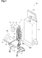
Fig. 2 , theoptical inspection apparatus 1 includes aleg unit 2 installed in a floor surface, and a quadrangular prism-shapedmain pole 3 vertically disposed on theleg unit 2. Aguide rail 4 extending in a vertical direction is provided to afront face 3a (a face on aconveying line 100 side) of themain pole 3. Aguide rail 5 extending in the vertical direction is provided to arear face 3b of themain pole 3. Abelt 6 is stretched over aright side face 3c (a face on the right as viewed from theconveying line 100 side) and aleft side face 3d of themain pole 3 through an upper end of themain pole 3. - An
inspection head 10 is mounted on theguide rail 4 so as to be movable along theguide rail 4. One end of thebelt 6 positioned on theright side face 3c of themain pole 3 is fixed to theinspection head 10. Aweight 7 is mounted on theguide rail 5 so as to be movable along theguide rail 5. The other end of thebelt 6 positioned on theleft side face 3d of themain pole 3 is fixed to theweight 7. - In this configuration, as illustrated in
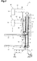
Fig. 3 , by moving theinspection head 10 up along theguide rail 4, theweight 7 is moved down along theguide rail 5. On the other hand, by moving theinspection head 10 down along theguide rail 4, theweight 7 is moved up along theguide rail 5. Once theinspection head 10 is disposed to a desired height, theinspection head 10 is fixed to themain pole 3 by alever 8. In this way, by using theweight 7, a vertical movement of theinspection head 10 relative to themain pole 3 is made smooth in theoptical inspection apparatus 1. - As illustrated in
Fig. 2 , theinspection head 10 includes: alight radiation unit 11 configured to radiate light to thearticle 50; alight detection unit 12 configured to detect transmitted light of the light radiated to thearticle 50; and asupport unit 13 configured to support thelight radiation unit 11 and thelight detection unit 12 in a cantilever manner. Thelight radiation unit 11 is disposed below thegap 103 between thesuccessive conveyers light detection unit 12 is disposed above thegap 103. An optical path of the light from thelight radiation unit 11 to thelight detection unit 12 is exposed to an ambient atmosphere. That is, an inspection region of thearticle 50 by the light is exposed to the ambient atmosphere and is not covered with a shield box or the like. Note that a cover may be provided to shield ambient light so as to cover at least a part of the inspection region. - The
light radiation unit 11 has a plurality of LEDs disposed along a horizontal direction (direction in which thegap 103 extends). At the time when thearticle 50 passes above thegap 103 between thesuccessive conveyers light radiation unit 11 radiates near infrared light to thearticle 50 through thegap 103. Note that a wavelength of the near infrared light is from 780 nm to 1100 nm. - The
light detection unit 12 is a line sensor and has a plurality of PDs disposed along the horizontal direction (direction in which thegap 103 extends). At the time when thearticle 50 passes above thegap 103 between thesuccessive conveyers light detection unit 12 detects transmitted light of the near infrared light radiated to thearticle 50 and outputs a detection signal to thecontrol device 30. - The
support unit 13 includes: apole unit 16 has afirst pole part 14 and asecond pole part 15; afirst beam unit 17; and asecond beam unit 18. Thefirst pole part 14 is provided with aguide groove 14a extending in the vertical direction. Thesecond pole part 15 is mounted on theguide groove 14a so as to be movable along theguide groove 14a. Thefirst pole part 14 and thesecond pole part 15 are mutually fixed by alever 21. Astopper bolt 22 having a cushion member is fixed to a lower end of thesecond pole part 15 through along hole 14b formed in thefirst pole part 14. Accordingly, even in a case where thesecond pole part 15 is unintendedly dropped due to release of thelever 21, it is possible to stop dropping of thesecond pole part 15 while absorbing a shock. - One
end 17a of thefirst beam unit 17 is fixed to a lower end of thefirst pole part 14, and anotherend 17b of thefirst beam unit 17 is a free end. Thefirst beam unit 17 is provided with a recessedportion 17c opened upward, and thelight radiation unit 11 is housed in the recessedportion 17c. That is, being supported by thefirst beam unit 17, thelight radiation unit 11 is supported by thesupport unit 13 in the cantilever manner. - An opened portion of the recessed
portion 17c is covered with alight transmitting cover 23 placed on thefirst beam unit 17. Thecover 23 is formed by, for example, a light transmitting resin. In thecover 23, a cut-off 23a opened to an opposite side of theother end 17b of thefirst beam unit 17 is provided to a part corresponding to the oneend 17a of thefirst beam unit 17. In thecover 23, around hole 23b is provided to a part corresponding to theother end 17b of thefirst beam unit 17. Thecover 23 is positioned in thefirst beam unit 17 by apin 24a, which is vertically disposed on the oneend 17a of thefirst beam unit 17, being fitted into the cut-off 23a as well as by apin 24b, which is vertically disposed on theother end 17b of thefirst beam unit 17, being fitted into theround hole 23b. Note that each of thepins - One
end 18a of thesecond beam unit 18 is fixed to an upper end of thesecond pole part 15, and anotherend 18b of thesecond beam unit 18 is a free end. Thelight detection unit 12 is mounted on theother end 18b, or the free end, of thesecond beam unit 18. That is, thelight detection unit 12 is supported by thesecond beam unit 18, and thereby thelight detection unit 12 is supported by thesupport unit 13 in the cantilever manner. - In the above-described configuration of the
support unit 13, as illustrated inFig. 4 , in a state where thelever 21 is released, thelight detection unit 12 is moved up and down integrally with thesecond pole part 15 and thesecond beam unit 18. After thelight detection unit 12 is disposed to a desired height, thelight detection unit 12 is fixed relative to thelight radiation unit 11 as a result of thefirst pole part 14 and thesecond pole part 15 being fixed to each other by thelever 21. - As illustrated in
Fig. 2 , afirst plate 25 and asecond plate 26 each having a rectangular plate shape are mounted on the lower end of thefirst pole part 14. Thefirst plate 25 is mounted on theguide rail 4 so as to be movable along theguide rail 4. One end of thebelt 6 positioned on theright side face 3c of themain pole 3 is fixed to thefirst plate 25. Thesecond plate 26 is fixed to thefirst plate 25 by each ofbolts 27 inserted into each of arc-shapedlong holes 26a provided to each of four corners of thesecond plate 26. The lower end of thefirst pole part 14 is fixed to thesecond plate 26. - In this configuration, as illustrated in
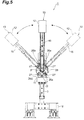
Fig. 5 , in a state where thebolt 27 is loose, theinspection head 10 is rotated within a range of the arc-shapedlong hole 26a. At this time, a position P to be a center of rotation of theinspection head 10 is center positions (center positions as viewed from the conveyingline 100 side) of thefirst plate 25 and thesecond plate 26, which are mounted on the lower end of thefirst pole part 14. In this way, a distance from thelight radiation unit 11 to the position P is shorter than a distance from thelight detection unit 12 to the position P. After theinspection head 10 is disposed to a desired angle, theinspection head 10 is fixed relative to themain pole 3 as a result of tightening each of thebolts 27. - As described above, in the
optical inspection apparatus 1, thelight radiation unit 11 and thelight detection unit 12 are supported by thesupport unit 13 in the cantilever manner, and the inspection region of thearticle 50 by the light is exposed to the ambient atmosphere. Thus, it is possible to easily install theoptical inspection apparatus 1 in the existing conveyingline 100 conveying thearticle 50 from one of sides of the conveyingline 100 such that thelight radiation unit 11 and thelight detection unit 12 face each other interposing thegap 103 between thesuccessive conveyers - Furthermore, in the
optical inspection apparatus 1, thelight detection unit 12 is disposed upward relative to thelight radiation unit 11. In this configuration, since thelight detection unit 12 faces downward, it is possible to suppress sticking of dust to thelight detection unit 12 that may more easily deteriorate detection accuracy than sticking of dust to thelight radiation unit 11. It is also possible to suppress light such as illumination around theoptical inspection apparatus 1 from entering thelight detection unit 12 as ambient light. Moreover, it is possible to easily clean thelight detection unit 12 in a large space above the existing conveyingline 100. - In the
optical inspection apparatus 1, thelight radiation unit 11 disposed below thelight detection unit 12 is covered with thelight transmitting cover 23. In this configuration, in a case where dust sticks to thecover 23, it is possible to clean thecover 23 by detaching thecover 23 or to replace it with anew cover 23. In particular, in thefirst beam unit 17, since thecover 23 is positioned by thepin 24a being fitted into the cut-off 23a as well as by thepin 24b being fitted into theround hole 23b, even in a case where a space between the existing conveyingline 100 and thefirst beam unit 17 is small, by sliding thecover 23 in the horizontal direction, it is possible to attach or detach thecover 23 to or from thefirst beam unit 17 without using a tool or the like. Note that thecover 23 may also have a lens function for concentrating light emitted from thelight radiation unit 11 or a filter function for blocking light of a predetermined wavelength. - While a distance equivalent to a focal distance is necessary between a conveyance surface of the existing conveying
line 100 and thelight detection unit 12, it is preferred that a distance between the conveyance surface thereof and thelight radiation unit 11 be small from a viewpoint of suppressing attenuation of light to be radiated to thearticle 50. Since thelight detection unit 12 is disposed upward relative to thelight radiation unit 11 in theoptical inspection apparatus 1, it is possible to easily install theoptical inspection apparatus 1 in the conveyingline 100 even in a case where a height of the conveyance surface of the existing conveyingline 100 is low. - In the
optical inspection apparatus 1, thelight radiation unit 11 and thelight detection unit 12 is vertically movable integrally with thesupport unit 13. In this configuration, it is possible to easily adjust positions of thelight radiation unit 11 and thelight detection unit 12 relative to the existing conveyingline 100. - In the
optical inspection apparatus 1, the position of thelight detection unit 12 is adjustable relative to that of thelight radiation unit 11. In this configuration, it is possible to accurately adjust the position of thelight detection unit 12 and to focus thelight detection unit 12 on thearticle 50. - In the
optical inspection apparatus 1, thelight radiation unit 11 and thelight detection unit 12 are rotatable integrally with thesupport unit 13. In this configuration, in a case where the conveyance surface of thesuccessive conveyers line 100 is tilted, for example, it is possible to easily adjust angles of thelight radiation unit 11 and thelight detection unit 12 relative to the existing conveyingline 100 such that thelight radiation unit 11 and thelight detection unit 12 face each other in a direction perpendicular to the conveyance surface. - In the
optical inspection apparatus 1, thelight radiation unit 11 and thelight detection unit 12 are rotatable integrally with thesupport unit 13 about the position P, which is at a shorter distance from thelight radiation unit 11 than that from thelight detection unit 12, as a center. In this configuration, since a rotation amount of thelight radiation unit 11 is smaller than a rotation amount of thelight detection unit 12, by disposing thelight radiation unit 11 in the vicinity of thegap 103 between thesuccessive conveyers light detection unit 12 caused by the attenuation of the light to be radiated to thearticle 50. Furthermore, the rotation amount of thelight radiation unit 11, which is positioned in a space below the existing conveyingline 100, is smaller than the rotation amount of thelight detection unit 12, which is positioned in a space above the existing conveyingline 100. Thus, it is possible to suppress interference between thelight radiation unit 11 and any member of the conveyingline 100 within the small space below the existing conveyingline 100. - In the
optical inspection apparatus 1, thesupport unit 13 includes: thepole unit 16; thefirst beam unit 17 fixed to thepole unit 16 at the oneend 17a thereof; and thesecond beam unit 18 fixed to thepole unit 16 at the oneend 18a thereof. Thefirst beam unit 17 supports thelight radiation unit 11, and thesecond beam unit 18 supports thelight detection unit 12. In this configuration, compared to a case where thelight radiation unit 11 and thelight detection unit 12 are supported by a support unit having a curved shape, for example, it is possible to dispose thelight radiation unit 11 and thelight detection unit 12 to desired positions while suppressing interference between thesupport unit 13 and the existing conveyingline 100. - In the
optical inspection apparatus 1, the light radiated by thelight radiation unit 11 is the near infrared light. In this way, by using the near infrared light, which has higher transmissivity than visible light, it is possible to accurately inspect a condition of thearticle 50. - Now, image processing performed by the control device (control unit) 30 is described herein. As illustrated in
Fig. 6 , the object to be inspected is thearticle 50 in which a seasoning for an instant food, for example, is packed ascontents 52 in each ofpackages 51 of successive packaging (a plurality of connected small bags). Thecontents 52 caught in the sealed portion of thepackage 51 are inspected as described below. Note that such control device may also be provided in theoptical inspection apparatus 1. - First, a light transmission image of the
article 50 is acquired based on a detection signal output from theoptical inspection apparatus 1. Next, a registration mark (mark) 51a is detected in the light transmission image of thearticle 50. Subsequently, based on a positional relationship of the sealed portion to theregistration mark 51a saved in advance, aninspection region 51b corresponding to the sealed portion is set. Subsequently, by using theinspection region 51b as a target, thecontents 52 caught in the sealed portion of thepackage 51 is inspected. - In this way, by using the
registration mark 51a in which the attenuation of the light is large, it is possible to easily and securely set the sealed portion corresponding to theinspection region 51b. Note that by limiting theinspection region 51b by using mask processing or the like, it is possible to increase a processing speed. Note also that thepackage 51 is not limited to the successive packaging and may also be single packaging. Furthermore, it is also possible to set theinspection region 51b corresponding to the sealed portion based on a positional relationship between the sealed portion and an outer edge of thepackage 51 saved in advance without using theregistration mark 51a. - One embodiment of the present invention has been described as above; however, the present invention is not to be limited to the above-described embodiment. For example, the light detection unit of the present invention is not limited to the line sensor and may also be an area sensor or the like. Furthermore, the light detection unit of the present invention may be provided with a filter that blocks light of a predetermined wavelength. For example, the light detection unit of the present invention may be provided with a filter that allows near infrared light to pass through while blocking visible light. Accordingly, in a case where the optical path of the near infrared light from the light radiation unit to the light detection unit is exposed to the ambient atmosphere, it is possible to prevent the visible light from entering the line sensor or the area sensor from the ambient atmosphere and becoming the ambient light. Furthermore, the light radiation unit of the present invention is not limited to one that radiates the near infrared light and may also be one that radiates visible light, ultraviolet light, infrared light, or the like. The light detection unit of the present invention may also be one that detects transmitted light of such light.
- According to the present invention, it is possible to provide an optical inspection apparatus that can be easily installed in an existing conveying line conveying an article.
- 1 ... optical inspection apparatus, 11 ... light radiation unit, 12 ... light detection unit, 13 ... support unit, 16 ... pole unit, 17 ... first beam unit, 17a ... one end, 18 ... second beam unit, 18a ... one end, 30 ... control device (control unit), 50 ... article, 51 ... package, 51b ... inspection region, and 52 ... contents.
Claims (9)
- An optical inspection apparatus comprising:a light radiation unit configured to radiate light to an article;a light detection unit configured to detect transmitted light of the light radiated to the article; anda support unit configured to support the light radiation unit and the light detection unit in a cantilever manner;wherein an inspection region of the article by the light is exposed to an ambient atmosphere.
- The optical inspection apparatus according to claim 1, wherein the light detection unit is disposed upward relative to the light radiation unit.
- The optical inspection apparatus according to claim 1 or 2, wherein the light radiation unit and the light detection unit are vertically movable integrally with the support unit.
- The optical inspection apparatus according to claim 3, wherein a position of the light detection unit is adjustable relative to that of the light radiation unit.
- The optical inspection apparatus according to any one of claims 1 to 4, wherein the light radiation unit and the light detection unit are rotatable integrally with the support unit.
- The optical inspection apparatus according to claim 5, wherein the light radiation unit and the light detection unit are rotatable integrally with the support unit about a position as a center, the position being at a shorter distance from the light radiation unit than a distance from the light detection unit.
- The optical inspection apparatus according to any one of claims 1 to 6, wherein the support unit includes:a pole unit;a first beam unit fixed to the pole unit at one end thereof and configured to support the light radiation unit; anda second beam unit fixed to the pole unit at one end thereof and configured to support the light detection unit.
- The optical inspection apparatus according to any one of claims 1 to 7, wherein the light is near infrared light.
- The optical inspection apparatus according to any one of claims 1 to 8, further comprising a control unit configured to acquire a light transmission image of the article having contents contained in a package from the light detection unit, to set an inspection region corresponding to a sealed portion of the package based on a positional relationship of the sealed portion saved in advance, and to inspect the contents caught in the sealed portion with targeting the inspection region.
Applications Claiming Priority (2)
| Application Number | Priority Date | Filing Date | Title |
|---|---|---|---|
| JP2013258319A JP6335499B2 (en) | 2013-12-13 | 2013-12-13 | Optical inspection device |
| PCT/JP2014/079865 WO2015087653A1 (en) | 2013-12-13 | 2014-11-11 | Optical inspection device |
Publications (3)
| Publication Number | Publication Date |
|---|---|
| EP3081925A1 true EP3081925A1 (en) | 2016-10-19 |
| EP3081925A4 EP3081925A4 (en) | 2017-07-19 |
| EP3081925B1 EP3081925B1 (en) | 2020-01-01 |
Family
ID=53370968
Family Applications (1)
| Application Number | Title | Priority Date | Filing Date |
|---|---|---|---|
| EP14869756.8A Active EP3081925B1 (en) | 2013-12-13 | 2014-11-11 | Optical inspection device |
Country Status (5)
| Country | Link |
|---|---|
| US (1) | US9939387B2 (en) |
| EP (1) | EP3081925B1 (en) |
| JP (1) | JP6335499B2 (en) |
| CN (1) | CN105980836B (en) |
| WO (1) | WO2015087653A1 (en) |
Families Citing this family (5)
| Publication number | Priority date | Publication date | Assignee | Title |
|---|---|---|---|---|
| US9983736B1 (en) * | 2017-02-20 | 2018-05-29 | Peigen Jiang | Optical touch sensor |
| AT520798A1 (en) * | 2018-01-10 | 2019-07-15 | Insort Gmbh | Device for removing bad products from a product stream |
| JP2019128289A (en) * | 2018-01-25 | 2019-08-01 | セイコーエプソン株式会社 | Electronic component conveyance device and electronic component inspection device |
| KR20210018261A (en) * | 2018-06-07 | 2021-02-17 | 윌코아게 | A device that detects gas in the head space of the container |
| JP7143810B2 (en) * | 2019-04-26 | 2022-09-29 | トヨタ紡織株式会社 | inspection equipment |
Family Cites Families (27)
| Publication number | Priority date | Publication date | Assignee | Title |
|---|---|---|---|---|
| US4031752A (en) * | 1976-07-19 | 1977-06-28 | Art Sanders | Web process control apparatus |
| US4707138A (en) * | 1985-06-03 | 1987-11-17 | Filper Industries, Inc. | Color measuring and control device |
| EP0426851B1 (en) * | 1988-10-07 | 1997-01-02 | Hitachi, Ltd. | Apparatus for detecting particular substance |
| US4995531A (en) * | 1989-06-14 | 1991-02-26 | Bridgestone/Firestone, Inc. | Ring dispenser |
| US6411377B1 (en) * | 1991-04-02 | 2002-06-25 | Hitachi, Ltd. | Optical apparatus for defect and particle size inspection |
| US6610953B1 (en) * | 1998-03-23 | 2003-08-26 | University Of Arkansas | Item defect detection apparatus and method |
| US5917602A (en) * | 1998-04-30 | 1999-06-29 | Inex Inc. | System and method for image acquisition for inspection of articles on a moving conveyor |
| JP4949559B2 (en) * | 1999-03-19 | 2012-06-13 | ティテス ヴィションソルト アクチスカベット | Substance inspection |
| US6384421B1 (en) * | 1999-10-07 | 2002-05-07 | Logical Systems Incorporated | Vision system for industrial parts |
| JP2001221747A (en) * | 2000-02-03 | 2001-08-17 | Suntory Ltd | Imaging method of liquid filling container and device |
| JP3816426B2 (en) * | 2002-09-09 | 2006-08-30 | 株式会社ルネサステクノロジ | Process processing equipment |
| JP2004157027A (en) * | 2002-11-07 | 2004-06-03 | Nippon Alum Co Ltd | Powder inspection device |
| US20050188859A1 (en) * | 2004-03-01 | 2005-09-01 | The Enhancers, Inc. | Production meat analysis system and method |
| JP2006084794A (en) * | 2004-09-16 | 2006-03-30 | Olympus Corp | Observation device with focal position control mechanism |
| JP2008032621A (en) * | 2006-07-31 | 2008-02-14 | Hitachi High-Technologies Corp | Surface inspecting apparatus and method for same |
| DE102006036281B4 (en) * | 2006-08-03 | 2014-12-11 | Siemens Aktiengesellschaft | Method for generating stereo image pairs of an examination object with an X-ray system and X-ray system |
| JP2008076218A (en) * | 2006-09-21 | 2008-04-03 | Olympus Corp | Visual inspection apparatus |
| WO2008107892A1 (en) * | 2007-03-06 | 2008-09-12 | Advanced Vision Technology (Avt) Ltd. | System and method for detecting the contour of an object on a moving conveyor belt |
| JP5241245B2 (en) * | 2008-01-11 | 2013-07-17 | 株式会社日立ハイテクノロジーズ | Inspection apparatus and inspection method |
| BR112012002166B1 (en) * | 2009-07-29 | 2019-07-30 | American Science And Engineering, Inc. | INSPECTION SYSTEM FOR INSPECTING AN OBJECT |
| NO336546B1 (en) * | 2010-09-24 | 2015-09-21 | Tomra Sorting As | Apparatus and method for inspection of matter |
| JP2012189563A (en) * | 2011-03-10 | 2012-10-04 | System Square Inc | Optical inspection device |
| CN104737003B (en) * | 2012-10-17 | 2017-09-29 | 世高株式会社 | The check device of package body |
| JP6058977B2 (en) * | 2012-11-15 | 2017-01-11 | シャープ株式会社 | Fluorescence detection device |
| NL2009980C2 (en) * | 2012-12-13 | 2014-06-16 | Ct Voor Tech Informatica B V | A method of producing glass products from glass product material and an assembly for performing said method. |
| EP3048440B1 (en) * | 2013-09-18 | 2021-10-27 | Ishida Co., Ltd. | Inspection device |
| EP3045897B2 (en) * | 2013-10-03 | 2022-12-28 | System Square Inc. | Package inspection device |
-
2013
- 2013-12-13 JP JP2013258319A patent/JP6335499B2/en not_active Expired - Fee Related
-
2014
- 2014-11-11 WO PCT/JP2014/079865 patent/WO2015087653A1/en active Application Filing
- 2014-11-11 US US15/102,725 patent/US9939387B2/en not_active Expired - Fee Related
- 2014-11-11 EP EP14869756.8A patent/EP3081925B1/en active Active
- 2014-11-11 CN CN201480066961.0A patent/CN105980836B/en not_active Expired - Fee Related
Also Published As
| Publication number | Publication date |
|---|---|
| EP3081925A4 (en) | 2017-07-19 |
| JP2015114277A (en) | 2015-06-22 |
| EP3081925B1 (en) | 2020-01-01 |
| WO2015087653A1 (en) | 2015-06-18 |
| CN105980836B (en) | 2019-01-01 |
| CN105980836A (en) | 2016-09-28 |
| US20170023488A1 (en) | 2017-01-26 |
| US9939387B2 (en) | 2018-04-10 |
| JP6335499B2 (en) | 2018-05-30 |
Similar Documents
| Publication | Publication Date | Title |
|---|---|---|
| US9939387B2 (en) | Optical inspection device | |
| KR101300132B1 (en) | Apparatus for detecting particle in flat glass and detecting method using same | |
| US8983030B2 (en) | Inspection machine for printed circuit board | |
| US9733384B2 (en) | Package inspection system | |
| WO2008021807A3 (en) | X-ray inspection with contemporaneous and proximal transmission and backscatter imaging | |
| KR101482580B1 (en) | Glass bottle inspection device and telecentric lens unit | |
| US10882701B2 (en) | Method and apparatus for detecting faults during object transport | |
| NO336546B1 (en) | Apparatus and method for inspection of matter | |
| JP5687748B2 (en) | Inspection device | |
| GB201208184D0 (en) | Apparatus and method for measuring particle size distribution by light scattering | |
| WO2015083505A1 (en) | Near infrared ray inspection device | |
| JP5650002B2 (en) | X-ray foreign object detection device | |
| EP2600140A1 (en) | Inspection system | |
| KR102045818B1 (en) | Transmissive optical inspection device and method of detecting defect using the same | |
| JP2008275451A (en) | X-ray foreign matter detector | |
| JP2013246059A (en) | Defect inspection apparatus and defect inspection method | |
| JP3189176U (en) | Inspection device | |
| JP6100141B2 (en) | X-ray inspection equipment | |
| JP6852991B2 (en) | X-ray inspection equipment | |
| JP2007194888A (en) | Method of inspecting solid-state imaging device | |
| JP3189175U (en) | X-ray inspection equipment | |
| JP7328802B2 (en) | inspection equipment | |
| JP2020016544A (en) | Facility for inspecting inside of drum | |
| JP2012137324A (en) | Method and apparatus for inspecting foreign substances floating on liquid surface | |
| JP7407877B2 (en) | X-ray inspection equipment |
Legal Events
| Date | Code | Title | Description |
|---|---|---|---|
| PUAI | Public reference made under article 153(3) epc to a published international application that has entered the european phase |
Free format text: ORIGINAL CODE: 0009012 |
|
| 17P | Request for examination filed |
Effective date: 20160704 |
|
| AK | Designated contracting states |
Kind code of ref document: A1 Designated state(s): AL AT BE BG CH CY CZ DE DK EE ES FI FR GB GR HR HU IE IS IT LI LT LU LV MC MK MT NL NO PL PT RO RS SE SI SK SM TR |
|
| AX | Request for extension of the european patent |
Extension state: BA ME |
|
| DAX | Request for extension of the european patent (deleted) | ||
| A4 | Supplementary search report drawn up and despatched |
Effective date: 20170619 |
|
| RIC1 | Information provided on ipc code assigned before grant |
Ipc: G01N 21/89 20060101AFI20170612BHEP Ipc: G01N 21/94 20060101ALI20170612BHEP Ipc: G01N 21/95 20060101ALI20170612BHEP Ipc: G01N 21/90 20060101ALI20170612BHEP Ipc: G01N 21/84 20060101ALI20170612BHEP Ipc: G01N 21/88 20060101ALI20170612BHEP Ipc: G01N 21/59 20060101ALI20170612BHEP |
|
| STAA | Information on the status of an ep patent application or granted ep patent |
Free format text: STATUS: EXAMINATION IS IN PROGRESS |
|
| 17Q | First examination report despatched |
Effective date: 20180724 |
|
| GRAP | Despatch of communication of intention to grant a patent |
Free format text: ORIGINAL CODE: EPIDOSNIGR1 |
|
| STAA | Information on the status of an ep patent application or granted ep patent |
Free format text: STATUS: GRANT OF PATENT IS INTENDED |
|
| INTG | Intention to grant announced |
Effective date: 20190606 |
|
| GRAS | Grant fee paid |
Free format text: ORIGINAL CODE: EPIDOSNIGR3 |
|
| GRAA | (expected) grant |
Free format text: ORIGINAL CODE: 0009210 |
|
| STAA | Information on the status of an ep patent application or granted ep patent |
Free format text: STATUS: THE PATENT HAS BEEN GRANTED |
|
| AK | Designated contracting states |
Kind code of ref document: B1 Designated state(s): AL AT BE BG CH CY CZ DE DK EE ES FI FR GB GR HR HU IE IS IT LI LT LU LV MC MK MT NL NO PL PT RO RS SE SI SK SM TR |
|
| REG | Reference to a national code |
Ref country code: GB Ref legal event code: FG4D |
|
| REG | Reference to a national code |
Ref country code: CH Ref legal event code: EP Ref country code: AT Ref legal event code: REF Ref document number: 1220394 Country of ref document: AT Kind code of ref document: T Effective date: 20200115 |
|
| REG | Reference to a national code |
Ref country code: IE Ref legal event code: FG4D |
|
| REG | Reference to a national code |
Ref country code: DE Ref legal event code: R096 Ref document number: 602014059495 Country of ref document: DE |
|
| REG | Reference to a national code |
Ref country code: NL Ref legal event code: MP Effective date: 20200101 |
|
| REG | Reference to a national code |
Ref country code: LT Ref legal event code: MG4D |
|
| PG25 | Lapsed in a contracting state [announced via postgrant information from national office to epo] |
Ref country code: NL Free format text: LAPSE BECAUSE OF FAILURE TO SUBMIT A TRANSLATION OF THE DESCRIPTION OR TO PAY THE FEE WITHIN THE PRESCRIBED TIME-LIMIT Effective date: 20200101 Ref country code: RS Free format text: LAPSE BECAUSE OF FAILURE TO SUBMIT A TRANSLATION OF THE DESCRIPTION OR TO PAY THE FEE WITHIN THE PRESCRIBED TIME-LIMIT Effective date: 20200101 Ref country code: LT Free format text: LAPSE BECAUSE OF FAILURE TO SUBMIT A TRANSLATION OF THE DESCRIPTION OR TO PAY THE FEE WITHIN THE PRESCRIBED TIME-LIMIT Effective date: 20200101 Ref country code: FI Free format text: LAPSE BECAUSE OF FAILURE TO SUBMIT A TRANSLATION OF THE DESCRIPTION OR TO PAY THE FEE WITHIN THE PRESCRIBED TIME-LIMIT Effective date: 20200101 Ref country code: PT Free format text: LAPSE BECAUSE OF FAILURE TO SUBMIT A TRANSLATION OF THE DESCRIPTION OR TO PAY THE FEE WITHIN THE PRESCRIBED TIME-LIMIT Effective date: 20200527 Ref country code: CZ Free format text: LAPSE BECAUSE OF FAILURE TO SUBMIT A TRANSLATION OF THE DESCRIPTION OR TO PAY THE FEE WITHIN THE PRESCRIBED TIME-LIMIT Effective date: 20200101 Ref country code: NO Free format text: LAPSE BECAUSE OF FAILURE TO SUBMIT A TRANSLATION OF THE DESCRIPTION OR TO PAY THE FEE WITHIN THE PRESCRIBED TIME-LIMIT Effective date: 20200401 |
|
| PG25 | Lapsed in a contracting state [announced via postgrant information from national office to epo] |
Ref country code: LV Free format text: LAPSE BECAUSE OF FAILURE TO SUBMIT A TRANSLATION OF THE DESCRIPTION OR TO PAY THE FEE WITHIN THE PRESCRIBED TIME-LIMIT Effective date: 20200101 Ref country code: SE Free format text: LAPSE BECAUSE OF FAILURE TO SUBMIT A TRANSLATION OF THE DESCRIPTION OR TO PAY THE FEE WITHIN THE PRESCRIBED TIME-LIMIT Effective date: 20200101 Ref country code: BG Free format text: LAPSE BECAUSE OF FAILURE TO SUBMIT A TRANSLATION OF THE DESCRIPTION OR TO PAY THE FEE WITHIN THE PRESCRIBED TIME-LIMIT Effective date: 20200401 Ref country code: IS Free format text: LAPSE BECAUSE OF FAILURE TO SUBMIT A TRANSLATION OF THE DESCRIPTION OR TO PAY THE FEE WITHIN THE PRESCRIBED TIME-LIMIT Effective date: 20200501 Ref country code: GR Free format text: LAPSE BECAUSE OF FAILURE TO SUBMIT A TRANSLATION OF THE DESCRIPTION OR TO PAY THE FEE WITHIN THE PRESCRIBED TIME-LIMIT Effective date: 20200402 Ref country code: HR Free format text: LAPSE BECAUSE OF FAILURE TO SUBMIT A TRANSLATION OF THE DESCRIPTION OR TO PAY THE FEE WITHIN THE PRESCRIBED TIME-LIMIT Effective date: 20200101 |
|
| REG | Reference to a national code |
Ref country code: DE Ref legal event code: R097 Ref document number: 602014059495 Country of ref document: DE |
|
| PG25 | Lapsed in a contracting state [announced via postgrant information from national office to epo] |
Ref country code: SK Free format text: LAPSE BECAUSE OF FAILURE TO SUBMIT A TRANSLATION OF THE DESCRIPTION OR TO PAY THE FEE WITHIN THE PRESCRIBED TIME-LIMIT Effective date: 20200101 Ref country code: SM Free format text: LAPSE BECAUSE OF FAILURE TO SUBMIT A TRANSLATION OF THE DESCRIPTION OR TO PAY THE FEE WITHIN THE PRESCRIBED TIME-LIMIT Effective date: 20200101 Ref country code: EE Free format text: LAPSE BECAUSE OF FAILURE TO SUBMIT A TRANSLATION OF THE DESCRIPTION OR TO PAY THE FEE WITHIN THE PRESCRIBED TIME-LIMIT Effective date: 20200101 Ref country code: DK Free format text: LAPSE BECAUSE OF FAILURE TO SUBMIT A TRANSLATION OF THE DESCRIPTION OR TO PAY THE FEE WITHIN THE PRESCRIBED TIME-LIMIT Effective date: 20200101 Ref country code: ES Free format text: LAPSE BECAUSE OF FAILURE TO SUBMIT A TRANSLATION OF THE DESCRIPTION OR TO PAY THE FEE WITHIN THE PRESCRIBED TIME-LIMIT Effective date: 20200101 Ref country code: RO Free format text: LAPSE BECAUSE OF FAILURE TO SUBMIT A TRANSLATION OF THE DESCRIPTION OR TO PAY THE FEE WITHIN THE PRESCRIBED TIME-LIMIT Effective date: 20200101 |
|
| PLBE | No opposition filed within time limit |
Free format text: ORIGINAL CODE: 0009261 |
|
| STAA | Information on the status of an ep patent application or granted ep patent |
Free format text: STATUS: NO OPPOSITION FILED WITHIN TIME LIMIT |
|
| REG | Reference to a national code |
Ref country code: AT Ref legal event code: MK05 Ref document number: 1220394 Country of ref document: AT Kind code of ref document: T Effective date: 20200101 |
|
| 26N | No opposition filed |
Effective date: 20201002 |
|
| PG25 | Lapsed in a contracting state [announced via postgrant information from national office to epo] |
Ref country code: AT Free format text: LAPSE BECAUSE OF FAILURE TO SUBMIT A TRANSLATION OF THE DESCRIPTION OR TO PAY THE FEE WITHIN THE PRESCRIBED TIME-LIMIT Effective date: 20200101 Ref country code: IT Free format text: LAPSE BECAUSE OF FAILURE TO SUBMIT A TRANSLATION OF THE DESCRIPTION OR TO PAY THE FEE WITHIN THE PRESCRIBED TIME-LIMIT Effective date: 20200101 |
|
| PGFP | Annual fee paid to national office [announced via postgrant information from national office to epo] |
Ref country code: GB Payment date: 20201120 Year of fee payment: 7 Ref country code: DE Payment date: 20201119 Year of fee payment: 7 |
|
| PG25 | Lapsed in a contracting state [announced via postgrant information from national office to epo] |
Ref country code: SI Free format text: LAPSE BECAUSE OF FAILURE TO SUBMIT A TRANSLATION OF THE DESCRIPTION OR TO PAY THE FEE WITHIN THE PRESCRIBED TIME-LIMIT Effective date: 20200101 Ref country code: PL Free format text: LAPSE BECAUSE OF FAILURE TO SUBMIT A TRANSLATION OF THE DESCRIPTION OR TO PAY THE FEE WITHIN THE PRESCRIBED TIME-LIMIT Effective date: 20200101 |
|
| PG25 | Lapsed in a contracting state [announced via postgrant information from national office to epo] |
Ref country code: MC Free format text: LAPSE BECAUSE OF FAILURE TO SUBMIT A TRANSLATION OF THE DESCRIPTION OR TO PAY THE FEE WITHIN THE PRESCRIBED TIME-LIMIT Effective date: 20200101 |
|
| REG | Reference to a national code |
Ref country code: CH Ref legal event code: PL |
|
| PG25 | Lapsed in a contracting state [announced via postgrant information from national office to epo] |
Ref country code: LU Free format text: LAPSE BECAUSE OF NON-PAYMENT OF DUE FEES Effective date: 20201111 |
|
| REG | Reference to a national code |
Ref country code: BE Ref legal event code: MM Effective date: 20201130 |
|
| PG25 | Lapsed in a contracting state [announced via postgrant information from national office to epo] |
Ref country code: LI Free format text: LAPSE BECAUSE OF NON-PAYMENT OF DUE FEES Effective date: 20201130 Ref country code: CH Free format text: LAPSE BECAUSE OF NON-PAYMENT OF DUE FEES Effective date: 20201130 |
|
| PG25 | Lapsed in a contracting state [announced via postgrant information from national office to epo] |
Ref country code: IE Free format text: LAPSE BECAUSE OF NON-PAYMENT OF DUE FEES Effective date: 20201111 Ref country code: FR Free format text: LAPSE BECAUSE OF NON-PAYMENT OF DUE FEES Effective date: 20201130 |
|
| PG25 | Lapsed in a contracting state [announced via postgrant information from national office to epo] |
Ref country code: TR Free format text: LAPSE BECAUSE OF FAILURE TO SUBMIT A TRANSLATION OF THE DESCRIPTION OR TO PAY THE FEE WITHIN THE PRESCRIBED TIME-LIMIT Effective date: 20200101 Ref country code: MT Free format text: LAPSE BECAUSE OF FAILURE TO SUBMIT A TRANSLATION OF THE DESCRIPTION OR TO PAY THE FEE WITHIN THE PRESCRIBED TIME-LIMIT Effective date: 20200101 Ref country code: CY Free format text: LAPSE BECAUSE OF FAILURE TO SUBMIT A TRANSLATION OF THE DESCRIPTION OR TO PAY THE FEE WITHIN THE PRESCRIBED TIME-LIMIT Effective date: 20200101 |
|
| REG | Reference to a national code |
Ref country code: DE Ref legal event code: R119 Ref document number: 602014059495 Country of ref document: DE |
|
| PG25 | Lapsed in a contracting state [announced via postgrant information from national office to epo] |
Ref country code: MK Free format text: LAPSE BECAUSE OF FAILURE TO SUBMIT A TRANSLATION OF THE DESCRIPTION OR TO PAY THE FEE WITHIN THE PRESCRIBED TIME-LIMIT Effective date: 20200101 Ref country code: AL Free format text: LAPSE BECAUSE OF FAILURE TO SUBMIT A TRANSLATION OF THE DESCRIPTION OR TO PAY THE FEE WITHIN THE PRESCRIBED TIME-LIMIT Effective date: 20200101 |
|
| GBPC | Gb: european patent ceased through non-payment of renewal fee |
Effective date: 20211111 |
|
| PG25 | Lapsed in a contracting state [announced via postgrant information from national office to epo] |
Ref country code: BE Free format text: LAPSE BECAUSE OF NON-PAYMENT OF DUE FEES Effective date: 20201130 |
|
| PG25 | Lapsed in a contracting state [announced via postgrant information from national office to epo] |
Ref country code: GB Free format text: LAPSE BECAUSE OF NON-PAYMENT OF DUE FEES Effective date: 20211111 Ref country code: DE Free format text: LAPSE BECAUSE OF NON-PAYMENT OF DUE FEES Effective date: 20220601 |