EP3081624A1 - Tar reforming furnace - Google Patents
Tar reforming furnace Download PDFInfo
- Publication number
- EP3081624A1 EP3081624A1 EP14869814.5A EP14869814A EP3081624A1 EP 3081624 A1 EP3081624 A1 EP 3081624A1 EP 14869814 A EP14869814 A EP 14869814A EP 3081624 A1 EP3081624 A1 EP 3081624A1
- Authority
- EP
- European Patent Office
- Prior art keywords
- syngas
- reforming furnace
- oxidant
- primary
- lead
- Prior art date
- Legal status (The legal status is an assumption and is not a legal conclusion. Google has not performed a legal analysis and makes no representation as to the accuracy of the status listed.)
- Withdrawn
Links
Images




Classifications
-
- C—CHEMISTRY; METALLURGY
- C01—INORGANIC CHEMISTRY
- C01B—NON-METALLIC ELEMENTS; COMPOUNDS THEREOF; METALLOIDS OR COMPOUNDS THEREOF NOT COVERED BY SUBCLASS C01C
- C01B3/00—Hydrogen; Gaseous mixtures containing hydrogen; Separation of hydrogen from mixtures containing it; Purification of hydrogen; Reversible storage of hydrogen
- C01B3/02—Production of hydrogen; Production of gaseous mixtures containing hydrogen
-
- B—PERFORMING OPERATIONS; TRANSPORTING
- B01—PHYSICAL OR CHEMICAL PROCESSES OR APPARATUS IN GENERAL
- B01J—CHEMICAL OR PHYSICAL PROCESSES, e.g. CATALYSIS OR COLLOID CHEMISTRY; THEIR RELEVANT APPARATUS
- B01J19/00—Chemical, physical or physico-chemical processes in general; Their relevant apparatus
- B01J19/0046—Sequential or parallel reactions, e.g. for the synthesis of polypeptides or polynucleotides; Apparatus and devices for combinatorial chemistry or for making molecular arrays
-
- B—PERFORMING OPERATIONS; TRANSPORTING
- B01—PHYSICAL OR CHEMICAL PROCESSES OR APPARATUS IN GENERAL
- B01J—CHEMICAL OR PHYSICAL PROCESSES, e.g. CATALYSIS OR COLLOID CHEMISTRY; THEIR RELEVANT APPARATUS
- B01J7/00—Apparatus for generating gases
-
- C—CHEMISTRY; METALLURGY
- C01—INORGANIC CHEMISTRY
- C01B—NON-METALLIC ELEMENTS; COMPOUNDS THEREOF; METALLOIDS OR COMPOUNDS THEREOF NOT COVERED BY SUBCLASS C01C
- C01B3/00—Hydrogen; Gaseous mixtures containing hydrogen; Separation of hydrogen from mixtures containing it; Purification of hydrogen; Reversible storage of hydrogen
- C01B3/02—Production of hydrogen; Production of gaseous mixtures containing hydrogen
- C01B3/32—Production of hydrogen; Production of gaseous mixtures containing hydrogen by reaction of gaseous or liquid organic compounds with gasifying agents, e.g. water, carbon dioxide or air
- C01B3/34—Production of hydrogen; Production of gaseous mixtures containing hydrogen by reaction of gaseous or liquid organic compounds with gasifying agents, e.g. water, carbon dioxide or air by reaction of hydrocarbons with gasifying agents
- C01B3/36—Production of hydrogen; Production of gaseous mixtures containing hydrogen by reaction of gaseous or liquid organic compounds with gasifying agents, e.g. water, carbon dioxide or air by reaction of hydrocarbons with gasifying agents using oxygen; using mixtures containing oxygen as gasifying agents
-
- C—CHEMISTRY; METALLURGY
- C01—INORGANIC CHEMISTRY
- C01B—NON-METALLIC ELEMENTS; COMPOUNDS THEREOF; METALLOIDS OR COMPOUNDS THEREOF NOT COVERED BY SUBCLASS C01C
- C01B3/00—Hydrogen; Gaseous mixtures containing hydrogen; Separation of hydrogen from mixtures containing it; Purification of hydrogen; Reversible storage of hydrogen
- C01B3/50—Separation of hydrogen or hydrogen-containing gases from gaseous mixtures, e.g. purification
-
- C—CHEMISTRY; METALLURGY
- C10—PETROLEUM, GAS OR COKE INDUSTRIES; TECHNICAL GASES CONTAINING CARBON MONOXIDE; FUELS; LUBRICANTS; PEAT
- C10J—PRODUCTION OF PRODUCER GAS, WATER-GAS, SYNTHESIS GAS FROM SOLID CARBONACEOUS MATERIAL, OR MIXTURES CONTAINING THESE GASES; CARBURETTING AIR OR OTHER GASES
- C10J3/00—Production of combustible gases containing carbon monoxide from solid carbonaceous fuels
-
- C—CHEMISTRY; METALLURGY
- C10—PETROLEUM, GAS OR COKE INDUSTRIES; TECHNICAL GASES CONTAINING CARBON MONOXIDE; FUELS; LUBRICANTS; PEAT
- C10K—PURIFYING OR MODIFYING THE CHEMICAL COMPOSITION OF COMBUSTIBLE GASES CONTAINING CARBON MONOXIDE
- C10K3/00—Modifying the chemical composition of combustible gases containing carbon monoxide to produce an improved fuel, e.g. one of different calorific value, which may be free from carbon monoxide
- C10K3/001—Modifying the chemical composition of combustible gases containing carbon monoxide to produce an improved fuel, e.g. one of different calorific value, which may be free from carbon monoxide by thermal treatment
- C10K3/003—Reducing the tar content
- C10K3/005—Reducing the tar content by partial oxidation
-
- B—PERFORMING OPERATIONS; TRANSPORTING
- B01—PHYSICAL OR CHEMICAL PROCESSES OR APPARATUS IN GENERAL
- B01J—CHEMICAL OR PHYSICAL PROCESSES, e.g. CATALYSIS OR COLLOID CHEMISTRY; THEIR RELEVANT APPARATUS
- B01J2219/00—Chemical, physical or physico-chemical processes in general; Their relevant apparatus
- B01J2219/00274—Sequential or parallel reactions; Apparatus and devices for combinatorial chemistry or for making arrays; Chemical library technology
- B01J2219/00277—Apparatus
- B01J2219/00495—Means for heating or cooling the reaction vessels
-
- B—PERFORMING OPERATIONS; TRANSPORTING
- B01—PHYSICAL OR CHEMICAL PROCESSES OR APPARATUS IN GENERAL
- B01J—CHEMICAL OR PHYSICAL PROCESSES, e.g. CATALYSIS OR COLLOID CHEMISTRY; THEIR RELEVANT APPARATUS
- B01J2219/00—Chemical, physical or physico-chemical processes in general; Their relevant apparatus
- B01J2219/00274—Sequential or parallel reactions; Apparatus and devices for combinatorial chemistry or for making arrays; Chemical library technology
- B01J2219/00583—Features relative to the processes being carried out
- B01J2219/0059—Sequential processes
-
- B—PERFORMING OPERATIONS; TRANSPORTING
- B01—PHYSICAL OR CHEMICAL PROCESSES OR APPARATUS IN GENERAL
- B01J—CHEMICAL OR PHYSICAL PROCESSES, e.g. CATALYSIS OR COLLOID CHEMISTRY; THEIR RELEVANT APPARATUS
- B01J2219/00—Chemical, physical or physico-chemical processes in general; Their relevant apparatus
- B01J2219/00274—Sequential or parallel reactions; Apparatus and devices for combinatorial chemistry or for making arrays; Chemical library technology
- B01J2219/00718—Type of compounds synthesised
- B01J2219/00756—Compositions, e.g. coatings, crystals, formulations
-
- C—CHEMISTRY; METALLURGY
- C01—INORGANIC CHEMISTRY
- C01B—NON-METALLIC ELEMENTS; COMPOUNDS THEREOF; METALLOIDS OR COMPOUNDS THEREOF NOT COVERED BY SUBCLASS C01C
- C01B2203/00—Integrated processes for the production of hydrogen or synthesis gas
- C01B2203/02—Processes for making hydrogen or synthesis gas
- C01B2203/025—Processes for making hydrogen or synthesis gas containing a partial oxidation step
- C01B2203/0255—Processes for making hydrogen or synthesis gas containing a partial oxidation step containing a non-catalytic partial oxidation step
-
- C—CHEMISTRY; METALLURGY
- C01—INORGANIC CHEMISTRY
- C01B—NON-METALLIC ELEMENTS; COMPOUNDS THEREOF; METALLOIDS OR COMPOUNDS THEREOF NOT COVERED BY SUBCLASS C01C
- C01B2203/00—Integrated processes for the production of hydrogen or synthesis gas
- C01B2203/04—Integrated processes for the production of hydrogen or synthesis gas containing a purification step for the hydrogen or the synthesis gas
- C01B2203/0465—Composition of the impurity
- C01B2203/048—Composition of the impurity the impurity being an organic compound
-
- C—CHEMISTRY; METALLURGY
- C01—INORGANIC CHEMISTRY
- C01B—NON-METALLIC ELEMENTS; COMPOUNDS THEREOF; METALLOIDS OR COMPOUNDS THEREOF NOT COVERED BY SUBCLASS C01C
- C01B2203/00—Integrated processes for the production of hydrogen or synthesis gas
- C01B2203/06—Integration with other chemical processes
- C01B2203/061—Methanol production
-
- C—CHEMISTRY; METALLURGY
- C01—INORGANIC CHEMISTRY
- C01B—NON-METALLIC ELEMENTS; COMPOUNDS THEREOF; METALLOIDS OR COMPOUNDS THEREOF NOT COVERED BY SUBCLASS C01C
- C01B2203/00—Integrated processes for the production of hydrogen or synthesis gas
- C01B2203/08—Methods of heating or cooling
- C01B2203/0805—Methods of heating the process for making hydrogen or synthesis gas
- C01B2203/0833—Heating by indirect heat exchange with hot fluids, other than combustion gases, product gases or non-combustive exothermic reaction product gases
-
- C—CHEMISTRY; METALLURGY
- C01—INORGANIC CHEMISTRY
- C01B—NON-METALLIC ELEMENTS; COMPOUNDS THEREOF; METALLOIDS OR COMPOUNDS THEREOF NOT COVERED BY SUBCLASS C01C
- C01B2203/00—Integrated processes for the production of hydrogen or synthesis gas
- C01B2203/12—Feeding the process for making hydrogen or synthesis gas
- C01B2203/1205—Composition of the feed
- C01B2203/1211—Organic compounds or organic mixtures used in the process for making hydrogen or synthesis gas
- C01B2203/1235—Hydrocarbons
- C01B2203/1252—Cyclic or aromatic hydrocarbons
-
- C—CHEMISTRY; METALLURGY
- C01—INORGANIC CHEMISTRY
- C01B—NON-METALLIC ELEMENTS; COMPOUNDS THEREOF; METALLOIDS OR COMPOUNDS THEREOF NOT COVERED BY SUBCLASS C01C
- C01B2203/00—Integrated processes for the production of hydrogen or synthesis gas
- C01B2203/14—Details of the flowsheet
- C01B2203/142—At least two reforming, decomposition or partial oxidation steps in series
-
- C—CHEMISTRY; METALLURGY
- C01—INORGANIC CHEMISTRY
- C01B—NON-METALLIC ELEMENTS; COMPOUNDS THEREOF; METALLOIDS OR COMPOUNDS THEREOF NOT COVERED BY SUBCLASS C01C
- C01B2203/00—Integrated processes for the production of hydrogen or synthesis gas
- C01B2203/14—Details of the flowsheet
- C01B2203/146—At least two purification steps in series
-
- C—CHEMISTRY; METALLURGY
- C10—PETROLEUM, GAS OR COKE INDUSTRIES; TECHNICAL GASES CONTAINING CARBON MONOXIDE; FUELS; LUBRICANTS; PEAT
- C10J—PRODUCTION OF PRODUCER GAS, WATER-GAS, SYNTHESIS GAS FROM SOLID CARBONACEOUS MATERIAL, OR MIXTURES CONTAINING THESE GASES; CARBURETTING AIR OR OTHER GASES
- C10J2300/00—Details of gasification processes
- C10J2300/09—Details of the feed, e.g. feeding of spent catalyst, inert gas or halogens
- C10J2300/0913—Carbonaceous raw material
- C10J2300/0916—Biomass
- C10J2300/092—Wood, cellulose
-
- C—CHEMISTRY; METALLURGY
- C10—PETROLEUM, GAS OR COKE INDUSTRIES; TECHNICAL GASES CONTAINING CARBON MONOXIDE; FUELS; LUBRICANTS; PEAT
- C10J—PRODUCTION OF PRODUCER GAS, WATER-GAS, SYNTHESIS GAS FROM SOLID CARBONACEOUS MATERIAL, OR MIXTURES CONTAINING THESE GASES; CARBURETTING AIR OR OTHER GASES
- C10J2300/00—Details of gasification processes
- C10J2300/09—Details of the feed, e.g. feeding of spent catalyst, inert gas or halogens
- C10J2300/0913—Carbonaceous raw material
- C10J2300/093—Coal
-
- C—CHEMISTRY; METALLURGY
- C10—PETROLEUM, GAS OR COKE INDUSTRIES; TECHNICAL GASES CONTAINING CARBON MONOXIDE; FUELS; LUBRICANTS; PEAT
- C10J—PRODUCTION OF PRODUCER GAS, WATER-GAS, SYNTHESIS GAS FROM SOLID CARBONACEOUS MATERIAL, OR MIXTURES CONTAINING THESE GASES; CARBURETTING AIR OR OTHER GASES
- C10J2300/00—Details of gasification processes
- C10J2300/09—Details of the feed, e.g. feeding of spent catalyst, inert gas or halogens
- C10J2300/0913—Carbonaceous raw material
- C10J2300/0946—Waste, e.g. MSW, tires, glass, tar sand, peat, paper, lignite, oil shale
-
- C—CHEMISTRY; METALLURGY
- C10—PETROLEUM, GAS OR COKE INDUSTRIES; TECHNICAL GASES CONTAINING CARBON MONOXIDE; FUELS; LUBRICANTS; PEAT
- C10J—PRODUCTION OF PRODUCER GAS, WATER-GAS, SYNTHESIS GAS FROM SOLID CARBONACEOUS MATERIAL, OR MIXTURES CONTAINING THESE GASES; CARBURETTING AIR OR OTHER GASES
- C10J2300/00—Details of gasification processes
- C10J2300/16—Integration of gasification processes with another plant or parts within the plant
- C10J2300/1603—Integration of gasification processes with another plant or parts within the plant with gas treatment
Definitions
- the present invention relates to a tar reforming furnace.
- gasified gas syngas which is mixed gas of CO with H 2
- fuel solid fuel such as coal, wood-based biomass, waste plastic or various wet wastes.
- gasification of the solid fuel at lower temperature (600-900°C) in a gasification furnace produces tar-containing syngas.
- Tar condenses as the tar-containing syngas lowers in temperature.
- use of the syngas as chemosynthetic material, fuel for power generation or the like brings about problems such as clogging of piping and trouble in equipment due to tar and poisoning of a synthetic catalyst due to adhesion of tar in a downstream refinery, chemically synthesizing or power generation process.
- Patent Literatures 1 and 2 showing general state of the art pertinent to a tar reforming furnace which overcomes such problems.
- a tar reforming furnace disclosed in Patent Literature 1 is not a tar reforming furnace using oxidation reforming but resolves and removes tar in a honeycomb-structured heat storage body elevated in temperature, which is, however, complex in structure because of having a rotary mechanism for rotatively driving the heat storage body and highly tends to have insufficient tar reforming because of short residence time of the syngas at a hot area. Moreover, there is concern about leaking of the syngas from the rotary body, which may bring about tar remaining in the gas reformed.
- tar-containing exhaust gas is caused to flow through and is preheated by one of alternating introduction ducts into high-temperatured one of heat storage bodies and is further heated and burned in the furnace to remove tar; the exhaust gas made free from the tar heats the other of the heat storage bodies and is discharged through the other of the alternating discharge ducts; then, the flows of the exhaust gas are alternately changed over, thereby providing the regenerative tar reforming furnace.
- the unreformed tar-containing exhaust gas from the one of the alternating introduction ducts is discharged directly to the one of the alternating discharge ducts at the timing of alternation or changeover.
- the invention was made in view of the above-mentioned conventional problems and has its object to provide a tar reforming furnace which can satisfactorily conduct tar reforming with a simple structure and can prevent unreformed tar-containing syngas from being discharged at alternation.
- the invention is directed to a tar reforming furnace characterized in that it comprises a primary reforming furnace internally formed with syngas flow passages, a one-end-side heat storage body in a one-end-side lead-in-out port of the primary reforming furnace, the other-end-side heat storage body in the other-end-side lead-in-out port of the primary reforming furnace, a syngas alternating lead-in system for alternatingly introducing the syngas through one of the heat storage bodies into the flow passages in the primary reforming furnace, a primary-oxidant alternating supply system for alternatingly supplying an oxidant to the syngas introduced from the syngas alternating lead-in system through the one of the heat storage bodies into the flow passages in the primary reforming furnace, a syngas alternating lead-out system for alternatingly deriving the reformed syngas supplied with the oxidant by the primary-oxidant alternating supply system through the other of the heat storage bodies, a secondary reforming furnace into which is introduced the syngas from the primary reforming furnace through
- the tar reforming furnace is preferably configured to introduce the syngas from the syngas alternating lead-in system axially into the primary reforming furnace and supply the oxidant from the primary-oxidant alternating supply system tangentially to a virtual circle around an axis of the primary reforming furnace.
- the tar reforming furnace is preferably configured to introduce the syngas from the syngas alternating lead-out system axially into the secondary reforming furnace and supply the oxidant from the secondary-oxidant supply system tangentially to a virtual circle around an axis of the secondary reforming furnace.
- the tar reforming furnace is configured to supply the syngas supplied from the syngas alternating lead-in system to the one-end-side lead-in-out port of the primary reforming furnace and passed through the one-end-side heat storage body tangentially to a one-side one of the flow passages with circular cross-sections in the primary reforming furnace and introduce the oxidant from the primary-oxidant alternating supply system axially into the one-side flow passage with the circular cross-sections in the primary reforming furnace and is configured to supply the syngas supplied from the syngas alternating lead-in system to the other-end-side lead-in-out port of the primary reforming furnace and passed through the other-end-side heat storage body tangentially to the other-side flow passage with the circular cross-section in the primary reforming furnace and introduce the oxidant from the primary-oxidant alternating supply system axially into the other-side flow passage with the circular cross-section in the primary reforming furnace.
- the tar reforming furnace is preferably configured to supply the syngas from the syngas alternating lead-out system tangentially to the secondary reforming furnace with a circular cross-section and introduce the oxidant from the secondary-oxidant supply system axially to the secondary reforming furnace with the circular cross-section.
- the tar reforming furnace further comprises soot blowers for removing foreign matters attached to the heat storage bodies.
- a tar reforming furnace according to the invention can exhibit excellent effects that tar reforming can be satisfactorily conducted with a simple structure and unreformed tar-containing syngas can be prevented from being discharged at alternation.
- a system with the tar reforming furnace comprises, as shown in Fig. 4 , a gasification furnace 1 for gasification of solid fuel, a dust removal device 2 for dust removal of syngas produced in the gasification furnace 1 and the tar reforming furnace 3 for resolution and removal of tar from the syngas made free from dust in the dust removal device 2.
- the tar-containing syngas produced in the gasification furnace 1 is made free from dust in the dust removal device 2 and is introduced into the tar reforming furnace 3 where tar is resolved and removed.
- the gas with the tar being resolved and removed therefrom is subject to a pre- or refining-treatment (not shown) and then is used for power generation or as synthetic gas product such as methane, dimethyl ether (DME) or methanol.
- DME dimethyl ether
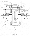
- the tar reforming furnace 3 comprises, as shown in Fig. 1 , a primary reforming furnace 4 with a U-shaped section and internally formed with flow passages 4a and 4b and a communication passage 4c for syngas.
- the primary reforming furnace 4 has one- and the other-end-side lead-in-out ports 5a and 5b with one- and the other-end-side heat storage bodies 6a and 6b, respectively.
- the lead-in-out ports 5a and 5b of the primary reforming furnace 4 are connected with a syngas alternating lead-in system 7 which alternatingly introduces the syngas through one of the heat storage bodies 6a and 6b to the flow passage 4a and 4b in the primary reforming furnace 4.
- the flow passages 4a and 4b in the primary reforming furnace 4 are connected with a primary-oxidant alternating supply system 8 which alternatingly supplies an oxidant (air or oxygen) to the syngas introduced into the flow passage 4a or 4b in the primary reforming furnace 4 by the syngas alternating lead-in system 7 at the one of the heat storage bodies 6a and 6b.
- a primary-oxidant alternating supply system 8 which alternatingly supplies an oxidant (air or oxygen) to the syngas introduced into the flow passage 4a or 4b in the primary reforming furnace 4 by the syngas alternating lead-in system 7 at the one of the heat storage bodies 6a and 6b.
- the lead-in-out ports 5a and 5b of the primary reforming furnace 4 are connected with a syngas alternating lead-out system 9 which alternatingly leads out or derives the reformed syngas supplied with the oxidant by the primary-oxidant alternating supply system 8 at the other of the heat storage bodies 6a and 6b.
- a secondary reforming furnace 10 is arranged to which introduced is the syngas from the primary reforming furnace 4 through the syngas alternating lead-out system 9.
- the secondary reforming furnace 10 is connected with a secondary-oxidant supply system 11 which supplies an oxidant (air or oxygen) to the introduced syngas only at alternation in the syngas alternating lead-in-out systems 7 and 9.
- the syngas alternating lead-in system 7 is constructed such that a syngas supply line 7L supplied with the syngas from the gasification furnace 1 through the dust removal device 2 (see Fig. 4 ) is branched and connected to the lead-in-out ports 5a and 5b of the primary reforming furnace 4 with syngas lead-in on-off valves 7a and 7b being arranged downstream of a branch point of the syngas supply line 7L, respectively, in a flow direction of the gas and being alternately opened/closed by an alternation control signal 7s from a controller 12.
- the primary-oxidant alternating supply system 8 is constructed such that primary-oxidant supply lines 8L supplied with the oxidant are connected to the flow passage 4a and 4b at positions below the heat storage bodies 6a and 6b in the primary reforming furnace 4 and the primary-oxidant supply lines 8L are provided with primary-oxidant on-off valves 8a and 8b, respectively, which are alternately opened/closed by an alternation control signal 8s from the controller 12.
- the syngas alternating lead-out system 9 is constructed such that syngas lead-out lines 9L connected with the lead-in-out ports 5a and 5b of the primary reforming furnace 4 are provided with syngas lead-out on-off valves 9a and 9b, respectively, which are alternately opened/closed by an alternation control signal 9s from the controller 12, the syngas lead-out lines 9L being joined together and connected to the secondary reforming furnace 10.
- the secondary-oxidant supply system 11 is constructed such that secondary-oxidant supply lines 11L supplied with the oxidant are connected to an upper portion of the secondary reforming furnace 10 and are provided with secondary oxidant on-off valves 11a, respectively, which are opened/closed by an alternation control signal 11s from the controller 12.
- a draft fan 13 Arranged downstream of the secondary reforming furnace 10 is a draft fan 13 which draws in the syngas.
- the flow passage or passages 4a or/and 4b at the positions below the heat storage bodies 6a and 6b or/and the communication passage 4c in the primary reforming furnace 4 are provided with preheating burners (not shown), respectively, using city gas or the like.
- the syngas is introduced axially into the primary reforming furnace 4 through the syngas supply line 7L in the syngas alternating lead-in system 7 while, as shown in Fig. 2 , the oxidant is supplied from the primary-oxidant supply lines 8L in the primary-oxidant alternating supply system 8 tangentially to a virtual circle C1 around an axis of the primary reforming furnace 4.
- Fig. 2 Exemplified in Fig. 2 is a case where the four primary-oxidant supply lines 8L are connected circumferentially of the primary reforming furnace 4; however, the number of the primary-oxidant supply lines 8L is not restricted thereto.
- the syngas is introduced axially into the secondary reforming furnace 10 through the syngas lead-out lines 9L of the syngas alternating lead-out system 9 while, as shown in Fig. 3 , the oxidant is supplied from the secondary-oxidant supply lines 11L in the secondary-oxidant supply system 11 tangentially to a virtual circle C2 around an axis of the secondary reforming furnace 10.
- Fig. 3 Exemplified in Fig. 3 is a case where the four secondary-oxidant supply lines 11L are connected circumferentially of the secondary reforming furnace 10; however, the number of the secondary-oxidant supply lines 11L is not restricted thereto.
- the tar-containing syngas produced in the gasification furnace 1 is made free from dust in the dust removal device 2 and is introduced into the tar reforming furnace 3.
- the inside of the primary reforming furnace 4 is elevated up to a predetermined temperature (on the order of about 1100°C) by the preheating burner or burners (not shown), using city gas or the like.
- the syngas lead-in on-off valves 7a and 7b incorporated in the syngas supply line 7L in the syngas alternating lead-in system 7 leading to the lead-in-out ports 5a and 5b of the primary reforming furnace 4 are opened and closed, respectively, by the alternation control signal 7s from the controller 12.
- the syngas lead-out on-off valves 9a and 9b incorporated in the syngas lead-out lines 9L in the syngas alternating lead-out system 9 connected to the lead-in-out ports 5a and 5b are closed and opened, respectively, by the alternation control signal 9s from the controller 12.
- the primary-oxidant on-off valves 8a and 8b incorporated in the one and the other primary-oxidant supply lines 8L in the primary-oxidant alternating supply system 8 connected to the flow passages 4a and 4b below the heat storage bodies 6a and 6b of the primary reforming furnace 4 are opened and closed, respectively, by the alternation control signal 8s from the controller 12.
- the tar-containing syngas is entered from the one-end-side lead-in-out port 5a of the primary reforming furnace 4 and is passed through and preheated by the one-end-side heat storage body 6a and then is blown with and oxidation reformed by the oxidant; then, the gas is passed through the flow passage 4a, the communication passage 4c, the flow passage 4b and the other-end-side heat storage body 6b; and then, the gas is guided through the other-end-side lead-in-out port 5b and through the secondary reforming furnace 10 and is passed downstream under pressure.
- the syngas lead-in on-off valves 7a and 7b incorporated in the syngas supply line 7L of the syngas alternating lead-in system 7 branched and leading to the lead-in-out ports 5a 5b of the primary reforming furnace 4 are closed and opened, respectively, by the alternation control signal 7s from the controller 12.
- the syngas lead-out on-off valves 9a and 9b incorporated in the syngas lead-out lines 9L in the syngas alternating lead-out system 9 connected to the lead-in-out ports 5a and 5b are opened and closed, respectively, by the alternation control signal 9s from the controller 12.
- the primary-oxidant on-off valves 8a and 8b incorporated in the one and the other primary-oxidant supply lines 8L in the primary-oxidant alternating supply system 8 connected to the flow passages 4a and 4b below the heat storage bodies 6a and 6b in the primary reforming furnace 4 is closed and opened, respectively, by the alternation control signal 8s from the controller 12.
- the tar-containing syngas is entered from the other-end-side lead-in-out port 5b of the primary reforming furnace 4 and passed through and preheated by the other-end-side heat storage body 6b and then is blown with and oxidation reformed by the oxidant; then, the gas is passed through the flow passage 4b, the communication passage 4c, the flow passage 4a and the one-end-side heat storage body 6a; and then, the gas is guided through the one-end-side lead-in-out port 5a and through the secondary reforming furnace 10 and is passed downstream under pressure.
- the unreformed tar-containing syngas may be discharged from the one- and the other-end-side lead-in-out ports 5a and 5b directly to the one and the other syngas lead-out lines 9L, respectively.
- the secondary-oxidant on-off valves 11a incorporated in the secondary-oxidant supply lines 11L in the secondary-oxidant supply system 11 connected to the upper portion of the secondary reforming furnace 10 are opened to supply the oxidant to the secondary reforming furnace 10 by the alternation control signal 11s from the controller 12.
- the alternation control signal 11s from the controller 12 the alternation control signal 11s from the controller 12.
- the syngas introduced from the syngas supply line 7L in the syngas alternating lead-in system 7 is axial to the primary reforming furnace 4 while, as shown in Fig. 2 , the oxidant suppled from the primary-oxidant supply lines 8L in the primary-oxidant alternating supply system 8 is tangential to the virtual circle C1 around the axis of the primary reforming furnace 4.
- the oxidant becomes a swirling flow to the syngas introduced axially into the primary reforming furnace 4, which facilitates the mixing and enables more efficient reforming of the tar contained in the syngas in the primary reforming furnace 4.
- the syngas introduced from the syngas lead-out lines 9L in the syngas alternating lead-out system 9 is axial to the secondary reforming furnace 10 while, as shown in Fig. 3 , the oxidant supplied from the secondary-oxidant supply lines 11L in the secondary-oxidant supply system 11 is tangential to the virtual circle C2 around the axis of the secondary reforming furnace 10.
- the oxidant becomes a swirling flow to the syngas introduced axially into the secondary reforming furnace 10, which facilitates the mixing and enables more efficient reforming of the tar contained in the syngas in the secondary reforming furnace 10 when the unreformed tar-containing syngas is introduced into the secondary reforming furnace 10 at the alternation.
- the oxidant becomes swirling flow to the syngas introduced axially into the primary reforming furnace 4, which facilitates mixing and enables more efficient reforming of the tar contained in the syngas within the primary reforming furnace 4.
- the oxidant becomes swirling flow to the syngas introduced axially into the secondary reforming furnace 10, which facilitates the mixing and enables more efficient reforming of the tar contained in the syngas in the secondary reforming furnace 10 when the unreformed tar-containing syngas is introduced into the secondary reforming furnace 10 at the alternation.
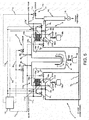
- Figs. 5-9 show a further embodiment of the tar reforming furnace according to the invention in which parts similar to those in Figs. 1-4 are represented by the same reference numerals and its fundamental structure is similar to that shown in Figs. 1-4 .
- syngas supplied from a syngas alternating lead-in system 7 to a one-end-side lead-in-out port 5a in a primary reforming furnace 4 and passed through a one-end-side heat storage body 6a is adapted to be supplied tangentially to a one-side one 4a of the flow passages with circular cross-sections in the primary reforming furnace 4 while oxidant is adapted to be introduced from a primary-oxidant alternating supply system 8 axially into the one-side flow passage 4a with the circular cross-section in the primary reforming furnace 4.
- the syngas supplied from the syngas alternating lead-in system 7 to the other-end-side lead-in-out port 5b in the primary reforming furnace 4 and passed through the other-end-side heat storage body 6b is adapted to be supplied tangentially to the other-side flow passage 4b with a circular cross-section in the primary reforming furnace 4 and the oxidant is adapted to be introduced from the primary-oxidant alternating supply system 8 axially into the other-side flow passage 4b with a circular cross-section in the primary reforming furnace 4.
- a one-end-side heat storage unit 14a filled with the one-end-side heat storage body 6a in the primary reforming furnace 4 is formed separately from the flow passage 4a in the primary reforming furnace 4, and upper portions of the flow passage 4a and of the one-end-side heat storage unit 14a are interconnected through a lead-in-out line 15a which is arranged to extend tangentially of the one flow passage 4a with the circular cross-section.
- the other-end-side heat storage unit 14 in the primary reforming furnace 4b filled with the other-end-side heat storage body 6b is formed separately from the flow passage 4b in the primary reforming furnace 4, and upper portions of the flow passage 4b and of the other-end-side heat storage unit 14b are interconnected through a lead-in-out line 15b which is arranged to extend tangentially of the other flow passage 4b with the circular cross-section.
- the syngas is supplied from a syngas lead-out line 9L in a syngas alternating lead-out system 9 tangentially to a secondary reforming furnace 10 with a circular cross-section while, as shown in Fig. 5 , the oxidant is introduced from a secondary-oxidant supply line 11L in a secondary-oxidant supply system 11 axially into the secondary reforming furnace 10 with the circular cross-section.
- Each of primary-oxidant supply nozzles 8N in the primary-oxidant alternating supply system 8 for introduction of the oxidant to the flow passages 4a and 4b in the primary reforming furnace 4 has a tip end formed with a plurality of (for example, four) injection holes 8h as shown in Figs. 8a and 8b so as to blow a primary oxidant to the flow passage 4a or 4b in a wide angle to further facilitate the mixing with the syngas.
- the primary-oxidant supply nozzle 8N may be replaced with a plurality of nozzles each with a single injection hole 8h.
- a secondary-oxidant supply nozzle in the secondary-oxidant supply system 11 may similarly have a tip end formed with a plurality of injection holes so as to blow a secondary oxidant to a secondary reforming furnace 10 in a wider angle to further facilitate the mixing with the syngas; alternatively, the secondary-oxidant supply nozzle may be replaced by a plurality of nozzles each with a single injection hole.
- the one- and the other-end-side heat storage units 14a and 14b are provided with soot blowers 16a and 16a' and soot blowers 16b and 16b' for removal of soot and other foreign matters attached to the one- and the other-end-side heat storage bodies 6a and 6b, respectively.
- Blow fluid lines 17L supplied with blow fluid such as nitrogen or other inert gas or steam are branched and connected to the soot blowers 16a and 16a' and the soot blowers 16b and 16b', respectively.
- the blow fluid lines 17L have, downstream of the branch points in directions of flow of blow fluid, blow fluid on-off valves 17a and 17a' and 17b and 17b', respectively, alternately opened/closed by an alternation control signal 17s from the controller 12.
- Pots 18a and 18b for recovery of soot and other foreign matters dropped by the operations of the soot blowers 16a and 16' and 16b and 16b' are connected to bottoms of the one- and the other-end-side heat storage units 14a and 14b through discharge pipes 20a and 20b with recovery valves 19a and 19b opened/closed as needs demands, respectively.
- a pot 18 for recovery of soot and other foreign matters entered into the flow passages 4a and 4b by the operations of the soot blowers 16a, 16a', 16b and 16b' is connected to a bottom of the communication passage 4c in the primary reforming furnace 4 through a discharge pipe 20 with a recovery valve 19 opened/closed as need demands.
- connected ends of the syngas supply and lead-out lines 7L and 9L to the other-end-side lead-in-out port 5b in the other-end-side heat storage unit 14b are formed with bend pipes 21b and 22b opened downwardly in the other-end-side lead-in-out port 5b so as not to accumulate the soot and other foreign matters in the syngas supply lines 7L and line 9L, respectively.
- the one- and the other-end-side heat storage bodies 6a and 6b are arranged on support members 23a and 23b, respectively.
- the tar-containing syngas produced in the gasification furnace 1 is made free from dust in the dust removal device 2 and is introduced into the tar reforming furnace 3.
- the syngas lead-in on-off valves 7a and 7b incorporated in the syngas supply line 7L in the syngas alternating lead-in system 7 leading to the lead-in-out ports 5a and 5b of the heat storage units 14a and 14b are opened and closed, respectively, by the alternation control signal 7s from the controller 12.
- the syngas lead-out on-off valves 9a and 9b incorporated in the syngas lead-out lines 9L in the syngas alternating lead-out system 9 connected to the lead-in-out ports 5a and 5b are closed and opened, respectively, by the alternation control signal 9s from the controller 12.
- the primary-oxidant on-off valves 8a and 8b incorporated in the one and the other primary-oxidant supply lines 8L in the primary-oxidant alternating supply system 8 axially connected to the flow passages 4a and 4b in the primary reforming furnace 4 is opened and closed, respectively, by the alternation control signal 8s from the controller 12.
- the tar-containing syngas is entered from the one-end-side lead-in-out port 5a in the primary reforming furnace 4 and is passed through and preheated by the one-end-side heat storage body 6a and then, as shown in Fig. 6 , is supplied through the lead-in-out line 15a tangentially to the one-side flow passage 4a with the circular cross-section while the oxidant is introduced from the primary-oxidant supply line 8L in the primary-oxidant alternating supply system 8 axially to the one-side flow passage 4a with the circular cross-section in the primary reforming furnace 4.
- each of the primary-oxidant supply nozzles 8N in the primary-oxidant alternating supply system 8 has a tip end formed with a plurality of (for example, four) injection holes 8h as shown in Figs. 8a and 8b so as to blow a primary oxidant to the flow passage 4a or 4b in a wider angle to further facilitate the mixing with the syngas. It is experimentally confirmed as shown in Fig.
- the syngas blown with and oxidation reformed by the oxidant is entered from the flow passage 4a, passed through the communication passage 4c, the flow passage 4b and the lead-in-out line 15b to the other-end-side heat storage body 6b and then is introduced though the other-end-side lead-in-out port 5b to the secondary reforming furnace 10 and is passed downstream under pressure.
- the syngas lead-in on-off valve 7a and 7b incorporated in the syngas supply line 7L in the syngas alternating lead-in system 7 branched and leading to the lead-in-out ports 5a and 5b of the primary reforming furnace 4 is closed and opened, respectively, by the alternation control signal 7s from the controller 12.
- the syngas lead-out on-off valves 9a and 9b incorporated in the syngas lead-out lines 9L in the syngas alternating lead-out system 9 connected to the lead-in-out ports 5a and 5b are opened and closed, respectively, by the alternation control signal 9s from the controller 12.
- the primary-oxidant on-off valves 8a and 8b incorporated in the one and the other primary-oxidant supply lines 8L in the primary-oxidant alternating supply system 8 connected axially to the flow passages 4a and 4b in the primary reforming furnace 4 is closed and opened, respectively, by the alternation control signal 8s from the controller 12.
- the tar-containing syngas is entered from the other-end-side lead-in-out port 5b in the primary reforming furnace 4 and is passed through and preheated by the other-end-side heat storage body 6b, and then, as shown in Fig. 6 , is supplied through the lead-in-out line 15b tangentially to the other side flow passage 4b with the circular cross-section while the oxidant is introduced from the primary-oxidant supply line 8L in the primary-oxidant alternating supply system 8 axially to the other side flow passage 4b with the circular cross-section in the primary reforming furnace 4.
- each of the primary-oxidant supply nozzles 8N in the primary-oxidant alternating supply system 8 has a tip end formed with a plurality of (for example, four) injection holes 8h as shown in Figs. 8a and 8b so as to blow the primary oxidant to the flow passage 4a or 4b in a wider angle to further facilitate the mixing with the syngas.
- a plurality of injection holes 8h as shown in Figs. 8a and 8b so as to blow the primary oxidant to the flow passage 4a or 4b in a wider angle to further facilitate the mixing with the syngas.
- the syngas blown with and oxidation reformed by the oxidant is entered from the flow passage 4b, passed through the communication passage 4c, the flow passage 4a and the lead-in-out line 15a to the one-end-side heat storage body 6a and is introduced through the one-end-side lead-in-out port 5a to the secondary reforming furnace 10 and is passed downstream under pressure.
- the unreformed tar-containing syngas may be discharged from the one- and the other-end-side lead-in-out ports 5a and 5b directly to the one and the other syngas lead-out lines 9L, respectively.
- the secondary-oxidant on-off valve 11a incorporated in the secondary-oxidant supply line 11L in the secondary-oxidant supply system 11 connected to the upper portion of the secondary reforming furnace 10 is opened to supply the oxidant to the secondary reforming furnace 10 by the alternation control signal 11s from the controller 12.
- the alternation control signal 11s from the controller 12 the alternation control signal 11s from the controller 12.
- the syngas is supplied through the syngas lead-out line 9L in the syngas alternating lead-out system 9 tangentially to the secondary reforming furnace 10 with the circular cross-section as shown in Fig. 7 while the oxidant is introduced from the secondary-oxidant supply line 11L in the secondary-oxidant supply system 11 axially to the secondary reforming furnace 10 with the circular cross-section as shown in Fig. 5 .
- the syngas becomes a swirling flow in the secondary reforming furnace 10 with the circular cross-section and the oxidant is axially introduced into the syngas as the swirling flow, which facilitates the mixing and enables more efficient reforming of the tar contained in the syngas also in the secondary reforming furnace 10.
- the syngas is entered through the one-end-side lead-in-out port 5a, is passed through the one-end-side heat storage body 6a, the lead-in-out line 15a and the one side flow passage 4a, the communication passage 4c, the flow passage 4b, the lead-in-out line 15b and the other-end-side heat storage body 6b and then is introduced into the other-end-side lead-in-out port 5b, the blow fluid on-off valves 17a and 17b' are opened and the blow fluid on-off valves 17a' and 17b are closed by the alternation control signal 17s from the controller 12 in accordance with the direction of flow of the syngas.
- blow fluid is blown to the one- and the other-end-side heat storage bodies 6a and 6b by the soot blowers 16a and 16b', respectively, whereby the soot and other foreign matters attached to the one- and the other-end-side heat storage bodies 6a and 6b are removed.
- the blow fluid is blown to the other- and the one-end-side heat storage body 6b and 6a by the soot blowers 16b and 16a', respectively, whereby the soot and other foreign matters attached to the other- and the one-end-side heat storage bodies 6b and 6a are removed.
- the one- and the other-end-side heat storage bodies 6a and 6b are prevented from being clogged and the syngas passed through the heat storage bodies 6a and 6b is prevented from being increased in pressure drop.
- the soot and other foreign matters dropped by the operations of the soot blowers 16a and 16a' and 16b and 16b' are recovered by the pots 18a and 18b through the discharge pipes 20a and 20b by opening the recovery valves 19a and 19b as need demands, respectively. Further, the soot and other foreign matters guided to the flow passages 4a and 4b are recovered by the discharge pipe 20 by opening the recovery valve 19 as need demands.
- the connected ends of the syngas supply and lead-out lines 7L and 9L to the one-end-side lead-in-out port 5a in the one-end-side heat storage unit 14a are provided with the bend pipes 21a and 22a opening downward in the one-end-side lead-in-out port 5a, respectively, so that there is no fear that the soot and other foreign matters accumulate in the syngas supply and lead-out lines 7L and 9L.
- the connected ends of the syngas supply and lead-out lines 7L and 9L to the other-end-side lead-in-out port 5b in the other-end-side heat storage unit 14b are provided with the bend pipes 21b and 22b opening downward in the other-end-side lead-in-out port 5b, respectively, so that there is no fear that the soot and other foreign matters accumulate in the syngas supply and lead-out lines 7L and 9L.
- the syngas becoming high-temperatured due to the mixing with the oxidant in the flow passage 4a flows through the communication passage 4c, the flow passage 4b, the lead-in-out line 15b and then to the other-end-side heat storage body 6b where the syngas is robbed of heat; the syngas robbed of heat flows into the other-end-side lead-in-out port 5b so that the support member 23b is prevented from being exposed to the high-temperatured syngas to suppress deterioration of the support member 23b.
- the syngas becoming high-temperatured in the mixing with the oxidant in the flow passage 4b flows through the communication passage 4c, the flow passage 4a, the lead-in-out line 15a and then to the one-end-side heat storage body 6a where the syngas is robbed of heat; the syngas robbed of heat flows into the one-end-side lead-in-out port 5a so that the support member 23a is prevented from being exposed to the high-temperatured syngas to suppress deterioration of the support member 23a.
- tar reforming can be satisfactorily conducted with the simple structure and unreformed tar-containing syngas can be prevented from being discharged at the alternation.
- the configuration that the syngas is supplied from the syngas alternating lead-out system 9 tangentially to the secondary reforming furnace 10 with the circular cross-section and the oxidant is introduced from the secondary-oxidant supply system 11 axially to the secondary reforming furnace 10 with the circular cross-section is preferable in that the syngas becomes swirling flow in the secondary reforming furnace 10 with the circular cross-section and the oxidant is introduced axially to the syngas as the swirling flow, which facilitates the mixing and enables more efficient reforming of the tar contained in the syngas also in the secondary reforming furnace 10.
- soot blowers 16a and 16a' and 16b and 16b' provided for removal of any foreign matters attached to the one- and the other-end-side heat storage bodies 6a and 6b can prevent the heat storage bodies 6a and 6b from being clogged and can suppress any increase in pressure drop of the syngas passed through the heat storage bodies 6a and 6b, respectively.
- a tar reforming furnace according to the invention is not limited to the above embodiments and that various changes and modifications may be made without departing from the scope of the invention.
- the soot blowers shown in the further embodiment may be arranged in the primary reforming furnace in the embodiment shown in Fig. 1 .
Landscapes
- Chemical & Material Sciences (AREA)
- Organic Chemistry (AREA)
- Engineering & Computer Science (AREA)
- Combustion & Propulsion (AREA)
- Chemical Kinetics & Catalysis (AREA)
- Inorganic Chemistry (AREA)
- Oil, Petroleum & Natural Gas (AREA)
- Physics & Mathematics (AREA)
- Thermal Sciences (AREA)
- General Chemical & Material Sciences (AREA)
- General Health & Medical Sciences (AREA)
- Health & Medical Sciences (AREA)
- Industrial Gases (AREA)
- Hydrogen, Water And Hydrids (AREA)
Abstract
Description
- The present invention relates to a tar reforming furnace.
- Development of a fuel gasification installation has been advanced for production of gasified gas (syngas which is mixed gas of CO with H2), using as fuel solid fuel such as coal, wood-based biomass, waste plastic or various wet wastes.
- Generally, gasification of the solid fuel at lower temperature (600-900°C) in a gasification furnace produces tar-containing syngas. Tar condenses as the tar-containing syngas lowers in temperature. As a result, use of the syngas as chemosynthetic material, fuel for power generation or the like brings about problems such as clogging of piping and trouble in equipment due to tar and poisoning of a synthetic catalyst due to adhesion of tar in a downstream refinery, chemically synthesizing or power generation process.
- Conventionally known technique for removal of tar contained in the syngas is tar reforming at high temperature in an oxidation reforming furnace. This is a technique of introducing the syngas produced in a gasification furnace into the oxidation reforming furnace where the syngas is burned with addition of air or oxygen into a temperature on the order of 1000-1400°C and concurrently tar contained is reformed through oxidation reforming or steam reforming.
- However, the conventional tar reforming furnace using the common oxidation reforming spends much in oxygen-purchasing cost or pure-oxygen-producing-installation and running costs, resulting in a factor of cost increase in a gasification system as a whole.
- There exist, for example,
Patent Literatures -
- [Patent Literature 1]
JP 3984535B - [Patent Literature 2]
JPH 11-51358A - A tar reforming furnace disclosed in
Patent Literature 1 is not a tar reforming furnace using oxidation reforming but resolves and removes tar in a honeycomb-structured heat storage body elevated in temperature, which is, however, complex in structure because of having a rotary mechanism for rotatively driving the heat storage body and highly tends to have insufficient tar reforming because of short residence time of the syngas at a hot area. Moreover, there is concern about leaking of the syngas from the rotary body, which may bring about tar remaining in the gas reformed. - In a tar reforming furnace disclosed in
Patent Literature 2, tar-containing exhaust gas is caused to flow through and is preheated by one of alternating introduction ducts into high-temperatured one of heat storage bodies and is further heated and burned in the furnace to remove tar; the exhaust gas made free from the tar heats the other of the heat storage bodies and is discharged through the other of the alternating discharge ducts; then, the flows of the exhaust gas are alternately changed over, thereby providing the regenerative tar reforming furnace. However, there is a fear that the unreformed tar-containing exhaust gas from the one of the alternating introduction ducts is discharged directly to the one of the alternating discharge ducts at the timing of alternation or changeover. - The invention was made in view of the above-mentioned conventional problems and has its object to provide a tar reforming furnace which can satisfactorily conduct tar reforming with a simple structure and can prevent unreformed tar-containing syngas from being discharged at alternation.
- The invention is directed to a tar reforming furnace characterized in that it comprises
a primary reforming furnace internally formed with syngas flow passages,
a one-end-side heat storage body in a one-end-side lead-in-out port of the primary reforming furnace,
the other-end-side heat storage body in the other-end-side lead-in-out port of the primary reforming furnace,
a syngas alternating lead-in system for alternatingly introducing the syngas through one of the heat storage bodies into the flow passages in the primary reforming furnace,
a primary-oxidant alternating supply system for alternatingly supplying an oxidant to the syngas introduced from the syngas alternating lead-in system through the one of the heat storage bodies into the flow passages in the primary reforming furnace,
a syngas alternating lead-out system for alternatingly deriving the reformed syngas supplied with the oxidant by the primary-oxidant alternating supply system through the other of the heat storage bodies,
a secondary reforming furnace into which is introduced the syngas from the primary reforming furnace through the syngas alternating lead-out system and
a secondary-oxidant supply system for supplying an oxidant to the syngas introduced into the secondary reforming furnace only at alternation in the syngas alternating lead-in and -out systems. - The tar reforming furnace is preferably configured to introduce the syngas from the syngas alternating lead-in system axially into the primary reforming furnace and supply the oxidant from the primary-oxidant alternating supply system tangentially to a virtual circle around an axis of the primary reforming furnace.
- The tar reforming furnace is preferably configured to introduce the syngas from the syngas alternating lead-out system axially into the secondary reforming furnace and supply the oxidant from the secondary-oxidant supply system tangentially to a virtual circle around an axis of the secondary reforming furnace.
- Alternatively, it is preferable that the tar reforming furnace is configured to supply the syngas supplied from the syngas alternating lead-in system to the one-end-side lead-in-out port of the primary reforming furnace and passed through the one-end-side heat storage body tangentially to a one-side one of the flow passages with circular cross-sections in the primary reforming furnace and introduce the oxidant from the primary-oxidant alternating supply system axially into the one-side flow passage with the circular cross-sections in the primary reforming furnace and
is configured to supply the syngas supplied from the syngas alternating lead-in system to the other-end-side lead-in-out port of the primary reforming furnace and passed through the other-end-side heat storage body tangentially to the other-side flow passage with the circular cross-section in the primary reforming furnace and introduce the oxidant from the primary-oxidant alternating supply system axially into the other-side flow passage with the circular cross-section in the primary reforming furnace. - The tar reforming furnace is preferably configured to supply the syngas from the syngas alternating lead-out system tangentially to the secondary reforming furnace with a circular cross-section and introduce the oxidant from the secondary-oxidant supply system axially to the secondary reforming furnace with the circular cross-section.
- Preferably, the tar reforming furnace further comprises soot blowers for removing foreign matters attached to the heat storage bodies.
- A tar reforming furnace according to the invention can exhibit excellent effects that tar reforming can be satisfactorily conducted with a simple structure and unreformed tar-containing syngas can be prevented from being discharged at alternation.
-
-
Fig. 1 is a conceptual diagram showing an embodiment of a tar reforming furnace according to the invention; -
Fig. 2 is a plan view showing a primary-oxidant alternating supply system in the embodiment of the tar reforming furnace according to the invention; -
Fig. 3 is a plan view showing a secondary-oxidant supply system in the embodiment of the tar reforming furnace according to the invention; -
Fig. 4 is a schematic diagram showing an example of a whole system including the tar reforming furnace according to the invention; -
Fig. 5 is a conceptual diagram showing a further embodiment of a tar reforming furnace according to the invention; -
Fig. 6 is a plan view showing supply directions of the syngas to the flow passages in the primary reforming furnace in the further embodiment of the tar reforming furnace according to the invention; -
Fig. 7 is a plan view showing a supply direction of the syngas to the secondary reforming furnace in the further embodiment of the tar reforming furnace according to the invention; -
Fig. 8a is a sectional view showing a tip end of a primary-oxidant supply nozzle in the further embodiment of the tar reforming furnace according to the invention; -
Fig. 8b is a front view of the tip end of the primary-oxidant supply nozzle in the further embodiment of the tar reforming furnace according to the invention; and -
Fig. 9 is a diagram showing differences in tar concentration and in reforming efficiency due to differences in number of injection holes on the primary-oxidant supply nozzle in the further embodiment of the tar reforming furnace according to the invention. - Embodiments of the invention will be described in conjunction with attached drawings.
-
Figs. 1-4 show an embodiment of a tar reforming furnace according to the invention. For example, a system with the tar reforming furnace comprises, as shown inFig. 4 , agasification furnace 1 for gasification of solid fuel, adust removal device 2 for dust removal of syngas produced in thegasification furnace 1 and thetar reforming furnace 3 for resolution and removal of tar from the syngas made free from dust in thedust removal device 2. In the system, the tar-containing syngas produced in thegasification furnace 1 is made free from dust in thedust removal device 2 and is introduced into thetar reforming furnace 3 where tar is resolved and removed. The gas with the tar being resolved and removed therefrom is subject to a pre- or refining-treatment (not shown) and then is used for power generation or as synthetic gas product such as methane, dimethyl ether (DME) or methanol. - The
tar reforming furnace 3 comprises, as shown inFig. 1 , a primary reformingfurnace 4 with a U-shaped section and internally formed withflow passages communication passage 4c for syngas. The primary reformingfurnace 4 has one- and the other-end-side lead-in-outports heat storage bodies - The lead-in-out
ports furnace 4 are connected with a syngas alternating lead-insystem 7 which alternatingly introduces the syngas through one of theheat storage bodies flow passage furnace 4. - The
flow passages furnace 4 are connected with a primary-oxidantalternating supply system 8 which alternatingly supplies an oxidant (air or oxygen) to the syngas introduced into theflow passage furnace 4 by the syngas alternating lead-insystem 7 at the one of theheat storage bodies - The lead-in-out
ports furnace 4 are connected with a syngas alternating lead-out system 9 which alternatingly leads out or derives the reformed syngas supplied with the oxidant by the primary-oxidantalternating supply system 8 at the other of theheat storage bodies - A secondary reforming
furnace 10 is arranged to which introduced is the syngas from the primary reformingfurnace 4 through the syngas alternating lead-out system 9. The secondary reformingfurnace 10 is connected with a secondary-oxidant supply system 11 which supplies an oxidant (air or oxygen) to the introduced syngas only at alternation in the syngas alternating lead-in-outsystems 7 and 9. - The syngas alternating lead-in
system 7 is constructed such that asyngas supply line 7L supplied with the syngas from thegasification furnace 1 through the dust removal device 2 (seeFig. 4 ) is branched and connected to the lead-in-outports furnace 4 with syngas lead-in on-offvalves syngas supply line 7L, respectively, in a flow direction of the gas and being alternately opened/closed by an alternation control signal 7s from acontroller 12. - The primary-oxidant alternating
supply system 8 is constructed such that primary-oxidant supply lines 8L supplied with the oxidant are connected to theflow passage heat storage bodies furnace 4 and the primary-oxidant supply lines 8L are provided with primary-oxidant on-offvalves alternation control signal 8s from thecontroller 12. - The syngas alternating lead-out system 9 is constructed such that syngas lead-out
lines 9L connected with the lead-in-outports furnace 4 are provided with syngas lead-out on-offvalves controller 12, the syngas lead-outlines 9L being joined together and connected to the secondary reformingfurnace 10. - The secondary-
oxidant supply system 11 is constructed such that secondary-oxidant supply lines 11L supplied with the oxidant are connected to an upper portion of the secondary reformingfurnace 10 and are provided with secondary oxidant on-offvalves 11a, respectively, which are opened/closed by analternation control signal 11s from thecontroller 12. - Arranged downstream of the secondary reforming
furnace 10 is adraft fan 13 which draws in the syngas. In order that an inside of the primary reformingfurnace 4 may be elevated in temperature up to a predetermined temperature (on the order of about 1100°C) before the introduction of the syngas, the flow passage orpassages 4a or/and 4b at the positions below theheat storage bodies communication passage 4c in the primary reformingfurnace 4 are provided with preheating burners (not shown), respectively, using city gas or the like. - It is preferable for facilitated mixing of the syngas with the oxidant that the syngas is introduced axially into the primary reforming
furnace 4 through thesyngas supply line 7L in the syngas alternating lead-insystem 7 while, as shown inFig. 2 , the oxidant is supplied from the primary-oxidant supply lines 8L in the primary-oxidant alternatingsupply system 8 tangentially to a virtual circle C1 around an axis of the primary reformingfurnace 4. Exemplified inFig. 2 is a case where the four primary-oxidant supply lines 8L are connected circumferentially of the primary reformingfurnace 4; however, the number of the primary-oxidant supply lines 8L is not restricted thereto. - It is preferable for facilitated mixing of the syngas with the oxidant that the syngas is introduced axially into the secondary reforming
furnace 10 through the syngas lead-outlines 9L of the syngas alternating lead-out system 9 while, as shown inFig. 3 , the oxidant is supplied from the secondary-oxidant supply lines 11L in the secondary-oxidant supply system 11 tangentially to a virtual circle C2 around an axis of the secondary reformingfurnace 10. Exemplified inFig. 3 is a case where the four secondary-oxidant supply lines 11L are connected circumferentially of the secondary reformingfurnace 10; however, the number of the secondary-oxidant supply lines 11L is not restricted thereto. - Next, a mode of operation of the above embodiment will be described.
- As shown in
Fig. 4 , the tar-containing syngas produced in thegasification furnace 1 is made free from dust in thedust removal device 2 and is introduced into thetar reforming furnace 3. Before introduction of the syngas into thetar reforming furnace 3, the inside of the primary reformingfurnace 4 is elevated up to a predetermined temperature (on the order of about 1100°C) by the preheating burner or burners (not shown), using city gas or the like. - In
Fig. 1 , the syngas lead-in on-offvalves syngas supply line 7L in the syngas alternating lead-insystem 7 leading to the lead-in-outports furnace 4 are opened and closed, respectively, by the alternation control signal 7s from thecontroller 12. In this state, the syngas lead-out on-offvalves lines 9L in the syngas alternating lead-out system 9 connected to the lead-in-outports controller 12. In this case, the primary-oxidant on-offvalves oxidant supply lines 8L in the primary-oxidant alternatingsupply system 8 connected to theflow passages heat storage bodies furnace 4 are opened and closed, respectively, by thealternation control signal 8s from thecontroller 12. - In this state, the tar-containing syngas is entered from the one-end-side lead-in-out
port 5a of the primary reformingfurnace 4 and is passed through and preheated by the one-end-sideheat storage body 6a and then is blown with and oxidation reformed by the oxidant; then, the gas is passed through theflow passage 4a, thecommunication passage 4c, theflow passage 4b and the other-end-sideheat storage body 6b; and then, the gas is guided through the other-end-side lead-in-outport 5b and through the secondary reformingfurnace 10 and is passed downstream under pressure. - After the elapse of a predetermined period of time (a few seconds to dozens of seconds), in
Fig. 1 , the syngas lead-in on-offvalves syngas supply line 7L of the syngas alternating lead-insystem 7 branched and leading to the lead-in-outports 5afurnace 4 are closed and opened, respectively, by the alternation control signal 7s from thecontroller 12. The syngas lead-out on-offvalves lines 9L in the syngas alternating lead-out system 9 connected to the lead-in-outports controller 12. In this case, the primary-oxidant on-offvalves oxidant supply lines 8L in the primary-oxidant alternatingsupply system 8 connected to theflow passages heat storage bodies furnace 4 is closed and opened, respectively, by thealternation control signal 8s from thecontroller 12. - In this state, the tar-containing syngas is entered from the other-end-side lead-in-out
port 5b of the primary reformingfurnace 4 and passed through and preheated by the other-end-sideheat storage body 6b and then is blown with and oxidation reformed by the oxidant; then, the gas is passed through theflow passage 4b, thecommunication passage 4c, theflow passage 4a and the one-end-sideheat storage body 6a; and then, the gas is guided through the one-end-side lead-in-outport 5a and through the secondary reformingfurnace 10 and is passed downstream under pressure. - As mentioned in the above, through the alternation in the syngas alternating lead-in and -out
systems 7 and 9 and in the primary-oxidant alternatingsupply system 8 at every predetermined time interval, the operations of the syngas being passed through and preheated by the one- and the other-end-sideheat storage bodies heat storage bodies - Here, at the timing of the alternation of the respective syngas lead-out on-off
valves ports lines 9L, respectively. - However, in accordance with the timing of the alternation of the respective syngas lead-out on-off
valves valves 11a incorporated in the secondary-oxidant supply lines 11L in the secondary-oxidant supply system 11 connected to the upper portion of the secondary reformingfurnace 10 are opened to supply the oxidant to the secondary reformingfurnace 10 by thealternation control signal 11s from thecontroller 12. Thus, unreformed tar is reformed in the secondary reformingfurnace 10 and is prevented from being discharged downstream without reformed. - As a result, unlike the tar reforming furnace disclosed in
Patent Literature 1, no rotary mechanism for rotatively driving the heat storage body is needed, which simplifies the structure and enables sufficient tar reforming because of long residence time of the syngas at the hot area. - Furthermore, unlike the tar reforming furnace disclosed in
Patent Literature 2, even if any unreformed tar-containing syngas is discharged through the one- or the other-end-side lead-in-outport out line 9L at the timing of the alternation, the oxidant is supplied to the secondary reformingfurnace 10 only at the alternation in the syngas alternating lead-in and -outsystems 7 and 9 and the unreformed tar is reformed. There is no fear of any unreformed tar being discharged downstream without reformed. - The syngas introduced from the
syngas supply line 7L in the syngas alternating lead-insystem 7 is axial to the primary reformingfurnace 4 while, as shown inFig. 2 , the oxidant suppled from the primary-oxidant supply lines 8L in the primary-oxidant alternatingsupply system 8 is tangential to the virtual circle C1 around the axis of the primary reformingfurnace 4. Thus, the oxidant becomes a swirling flow to the syngas introduced axially into the primary reformingfurnace 4, which facilitates the mixing and enables more efficient reforming of the tar contained in the syngas in the primary reformingfurnace 4. - Further, the syngas introduced from the syngas lead-out
lines 9L in the syngas alternating lead-out system 9 is axial to the secondary reformingfurnace 10 while, as shown inFig. 3 , the oxidant supplied from the secondary-oxidant supply lines 11L in the secondary-oxidant supply system 11 is tangential to the virtual circle C2 around the axis of the secondary reformingfurnace 10. Thus, the oxidant becomes a swirling flow to the syngas introduced axially into the secondary reformingfurnace 10, which facilitates the mixing and enables more efficient reforming of the tar contained in the syngas in the secondary reformingfurnace 10 when the unreformed tar-containing syngas is introduced into the secondary reformingfurnace 10 at the alternation. - Thus, with the simple structure, tar reforming can be satisfactorily conducted and the unreformed tar-containing syngas can be prevented from being discharged at the alternation.
- By the configuration to introduce the syngas from the syngas alternating lead-in
system 7 axially into the primary reformingfurnace 4 and supply the oxidant from the primary-oxidant alternatingsupply system 8 tangentially to the virtual circle C1 around the axis of the primary reformingfurnace 4, the oxidant becomes swirling flow to the syngas introduced axially into the primary reformingfurnace 4, which facilitates mixing and enables more efficient reforming of the tar contained in the syngas within the primary reformingfurnace 4. - Further, by the configuration to introduce the syngas from the syngas alternating lead-out system 9 axially into the secondary reforming
furnace 10 and supply the oxidant from the secondary-oxidant supply system 11 tangentially to the virtual circle C2 around the axis of the secondary reformingfurnace 10, the oxidant becomes swirling flow to the syngas introduced axially into the secondary reformingfurnace 10, which facilitates the mixing and enables more efficient reforming of the tar contained in the syngas in the secondary reformingfurnace 10 when the unreformed tar-containing syngas is introduced into the secondary reformingfurnace 10 at the alternation. -
Figs. 5-9 show a further embodiment of the tar reforming furnace according to the invention in which parts similar to those inFigs. 1-4 are represented by the same reference numerals and its fundamental structure is similar to that shown inFigs. 1-4 . - In the further embodiment, as shown in
Figs. 5 and6 , syngas supplied from a syngas alternating lead-insystem 7 to a one-end-side lead-in-outport 5a in a primary reformingfurnace 4 and passed through a one-end-sideheat storage body 6a is adapted to be supplied tangentially to a one-side one 4a of the flow passages with circular cross-sections in the primary reformingfurnace 4 while oxidant is adapted to be introduced from a primary-oxidant alternatingsupply system 8 axially into the one-side flow passage 4a with the circular cross-section in the primary reformingfurnace 4. Similarly, the syngas supplied from the syngas alternating lead-insystem 7 to the other-end-side lead-in-outport 5b in the primary reformingfurnace 4 and passed through the other-end-sideheat storage body 6b is adapted to be supplied tangentially to the other-side flow passage 4b with a circular cross-section in the primary reformingfurnace 4 and the oxidant is adapted to be introduced from the primary-oxidant alternatingsupply system 8 axially into the other-side flow passage 4b with a circular cross-section in the primary reformingfurnace 4. - In order to have the above-mentioned configuration, a one-end-side heat storage unit 14a filled with the one-end-side
heat storage body 6a in the primary reformingfurnace 4 is formed separately from theflow passage 4a in the primary reformingfurnace 4, and upper portions of theflow passage 4a and of the one-end-side heat storage unit 14a are interconnected through a lead-in-out line 15a which is arranged to extend tangentially of the oneflow passage 4a with the circular cross-section. Similarly, the other-end-side heat storage unit 14 in the primary reformingfurnace 4b filled with the other-end-sideheat storage body 6b is formed separately from theflow passage 4b in the primary reformingfurnace 4, and upper portions of theflow passage 4b and of the other-end-sideheat storage unit 14b are interconnected through a lead-in-out line 15b which is arranged to extend tangentially of theother flow passage 4b with the circular cross-section. - As shown in
Fig. 7 , the syngas is supplied from a syngas lead-out line 9L in a syngas alternating lead-out system 9 tangentially to a secondary reformingfurnace 10 with a circular cross-section while, as shown inFig. 5 , the oxidant is introduced from a secondary-oxidant supply line 11L in a secondary-oxidant supply system 11 axially into the secondary reformingfurnace 10 with the circular cross-section. - Each of primary-oxidant supply nozzles 8N in the primary-oxidant alternating
supply system 8 for introduction of the oxidant to theflow passages furnace 4 has a tip end formed with a plurality of (for example, four)injection holes 8h as shown inFigs. 8a and8b so as to blow a primary oxidant to theflow passage single injection hole 8h. Though not illustrated, a secondary-oxidant supply nozzle in the secondary-oxidant supply system 11 may similarly have a tip end formed with a plurality of injection holes so as to blow a secondary oxidant to a secondary reformingfurnace 10 in a wider angle to further facilitate the mixing with the syngas; alternatively, the secondary-oxidant supply nozzle may be replaced by a plurality of nozzles each with a single injection hole. - Further, as shown in
Fig. 5 , the one- and the other-end-sideheat storage units 14a and 14b are provided withsoot blowers soot blowers heat storage bodies fluid lines 17L supplied with blow fluid such as nitrogen or other inert gas or steam are branched and connected to thesoot blowers soot blowers blow fluid lines 17L have, downstream of the branch points in directions of flow of blow fluid, blow fluid on-offvalves controller 12. -
Pots soot blowers heat storage units 14a and 14b throughdischarge pipes recovery valves pot 18 for recovery of soot and other foreign matters entered into theflow passages soot blowers communication passage 4c in the primary reformingfurnace 4 through adischarge pipe 20 with arecovery valve 19 opened/closed as need demands. - Connected ends of the syngas supply and lead-out
lines port 5a in the one-end-side heat storage unit 14a are formed withbend pipes port 5a so as not to accumulate the soot and other foreign matters in the syngas supply and lead-outlines lines port 5b in the other-end-sideheat storage unit 14b are formed withbend pipes port 5b so as not to accumulate the soot and other foreign matters in thesyngas supply lines 7L andline 9L, respectively. - In the one- and the other-end-side
heat storage units 14a and 14b, the one- and the other-end-sideheat storage bodies support members 23a and 23b, respectively. - Next, a mode of operation of the above-mentioned further embodiment will be described.
- As shown in
Fig. 4 , the tar-containing syngas produced in thegasification furnace 1 is made free from dust in thedust removal device 2 and is introduced into thetar reforming furnace 3. - In
Fig. 5 , the syngas lead-in on-offvalves syngas supply line 7L in the syngas alternating lead-insystem 7 leading to the lead-in-outports heat storage units 14a and 14b are opened and closed, respectively, by the alternation control signal 7s from thecontroller 12. In this state, the syngas lead-out on-offvalves lines 9L in the syngas alternating lead-out system 9 connected to the lead-in-outports controller 12. In this case, the primary-oxidant on-offvalves oxidant supply lines 8L in the primary-oxidant alternatingsupply system 8 axially connected to theflow passages furnace 4 is opened and closed, respectively, by thealternation control signal 8s from thecontroller 12. - In this state, the tar-containing syngas is entered from the one-end-side lead-in-out
port 5a in the primary reformingfurnace 4 and is passed through and preheated by the one-end-sideheat storage body 6a and then, as shown inFig. 6 , is supplied through the lead-in-out line 15a tangentially to the one-side flow passage 4a with the circular cross-section while the oxidant is introduced from the primary-oxidant supply line 8L in the primary-oxidant alternatingsupply system 8 axially to the one-side flow passage 4a with the circular cross-section in the primary reformingfurnace 4. As a result, the syngas becomes swirling flow in the one-side flow passage 4a with the circular cross-section in the primary reformingfurnace 4 and the oxidant is axially introduced into the syngas as the swirling flow, which facilitates the mixing and enables more efficient reforming of the tar contained in the syngas in the primary reformingfurnace 4. Moreover, each of the primary-oxidant supply nozzles 8N in the primary-oxidant alternatingsupply system 8 has a tip end formed with a plurality of (for example, four)injection holes 8h as shown inFigs. 8a and8b so as to blow a primary oxidant to theflow passage Fig. 9 that the primary-oxidant supply nozzle 8N formed with the fourinjection holes 8h is lower both in heavy and light tar concentrations and higher in reforming efficiency than that with the single injection hole. The syngas blown with and oxidation reformed by the oxidant is entered from theflow passage 4a, passed through thecommunication passage 4c, theflow passage 4b and the lead-in-out line 15b to the other-end-sideheat storage body 6b and then is introduced though the other-end-side lead-in-outport 5b to the secondary reformingfurnace 10 and is passed downstream under pressure. - After the elapse of a predetermined period of time (a few seconds to dozens of seconds), in
Fig. 5 , the syngas lead-in on-offvalve syngas supply line 7L in the syngas alternating lead-insystem 7 branched and leading to the lead-in-outports furnace 4 is closed and opened, respectively, by the alternation control signal 7s from thecontroller 12. The syngas lead-out on-offvalves lines 9L in the syngas alternating lead-out system 9 connected to the lead-in-outports controller 12. In this case, the primary-oxidant on-offvalves oxidant supply lines 8L in the primary-oxidant alternatingsupply system 8 connected axially to theflow passages furnace 4 is closed and opened, respectively, by thealternation control signal 8s from thecontroller 12. - In this state, the tar-containing syngas is entered from the other-end-side lead-in-out
port 5b in the primary reformingfurnace 4 and is passed through and preheated by the other-end-sideheat storage body 6b, and then, as shown inFig. 6 , is supplied through the lead-in-out line 15b tangentially to the otherside flow passage 4b with the circular cross-section while the oxidant is introduced from the primary-oxidant supply line 8L in the primary-oxidant alternatingsupply system 8 axially to the otherside flow passage 4b with the circular cross-section in the primary reformingfurnace 4. As a result, the syngas becomes swirling flow in the other-side flow passage 4b with the circular cross-section in the primary reformingfurnace 4, and the oxidant is axially introduced into the syngas as the swirling flow, which facilitates mixing and enables more efficient reforming of the tar contained in the syngas in the primary reformingfurnace 4. Moreover, each of the primary-oxidant supply nozzles 8N in the primary-oxidant alternatingsupply system 8 has a tip end formed with a plurality of (for example, four)injection holes 8h as shown inFigs. 8a and8b so as to blow the primary oxidant to theflow passage Fig. 9 that the primary-oxidant supply nozzle 8N formed with the fourinjection holes 8h is lower both in heavy and light tar concentrations and higher in reforming efficiency than that with the single injection hole. The syngas blown with and oxidation reformed by the oxidant is entered from theflow passage 4b, passed through thecommunication passage 4c, theflow passage 4a and the lead-in-out line 15a to the one-end-sideheat storage body 6a and is introduced through the one-end-side lead-in-outport 5a to the secondary reformingfurnace 10 and is passed downstream under pressure. - As mentioned in the above, through the alternation in the syngas alternating lead-in and -out
systems 7 and 9 and in the primary-oxidant alternatingsupply system 8 at every predetermined time interval, the operations of the syngas being passed through and preheated by the one- and the other-end-sideheat storage bodies heat storage bodies - Here, at the timing of the alternation of the respective syngas lead-out on-off
valves ports lines 9L, respectively. - However, in accordance with the timing of the alternation of the respective syngas lead-out on-off
valves valve 11a incorporated in the secondary-oxidant supply line 11L in the secondary-oxidant supply system 11 connected to the upper portion of the secondary reformingfurnace 10 is opened to supply the oxidant to the secondary reformingfurnace 10 by thealternation control signal 11s from thecontroller 12. Thus, unreformed tar is reformed in the secondary reformingfurnace 10 and is prevented from being discharged downstream without reformed. Moreover, the syngas is supplied through the syngas lead-out line 9L in the syngas alternating lead-out system 9 tangentially to the secondary reformingfurnace 10 with the circular cross-section as shown inFig. 7 while the oxidant is introduced from the secondary-oxidant supply line 11L in the secondary-oxidant supply system 11 axially to the secondary reformingfurnace 10 with the circular cross-section as shown inFig. 5 . Thus, the syngas becomes a swirling flow in the secondary reformingfurnace 10 with the circular cross-section and the oxidant is axially introduced into the syngas as the swirling flow, which facilitates the mixing and enables more efficient reforming of the tar contained in the syngas also in the secondary reformingfurnace 10. - As a result, also in the further embodiment shown in
Figs. 5-9 , just like the embodiment shown inFigs. 1-4 , no rotary mechanism for rotatively driving the heat storage body is needed unlike the tar reforming furnace disclosed inPatent Literature 1, which simplifies the structure and enables sufficient tar reforming because of long residence time of the syngas at the hot area. - Furthermore, unlike the tar reforming furnace disclosed in
Patent Literature 2, even if any unreformed tar-containing syngas is discharged through the one- or the other-end-side lead-in-outport out line 9L at the timing of the alternation, the oxidant is supplied to the secondary reformingfurnace 10 only at the alternation in the syngas alternating lead-in and -outsystems 7 and 9 and the unreformed tar is reformed. There is no fear of any unreformed tar being discharged downstream without reformed. - Further, when the syngas is entered through the one-end-side lead-in-out
port 5a, is passed through the one-end-sideheat storage body 6a, the lead-in-out line 15a and the oneside flow passage 4a, thecommunication passage 4c, theflow passage 4b, the lead-in-out line 15b and the other-end-sideheat storage body 6b and then is introduced into the other-end-side lead-in-outport 5b, the blow fluid on-offvalves valves 17a' and 17b are closed by the alternation control signal 17s from thecontroller 12 in accordance with the direction of flow of the syngas. Thus, the blow fluid is blown to the one- and the other-end-sideheat storage bodies soot blowers heat storage bodies port 5b, is passed through the other-end-sideheat storage body 6b, the lead-in-out line 15b and the otherside flow passage 4b, thecommunication passage 4c, theflow passage 4a, the lead-in-out line 15a and the one-end-sideheat storage body 6a and then is introduced into the one-end-side lead-in-outport 5a, the blow fluid on-offvalves valves 17b' and 17a are closed by the alternation control signal 17s from thecontroller 12 in accordance with the direction of flow of the syngas. Thus, the blow fluid is blown to the other- and the one-end-sideheat storage body soot blowers heat storage bodies heat storage bodies heat storage bodies - The soot and other foreign matters dropped by the operations of the
soot blowers pots discharge pipes recovery valves flow passages discharge pipe 20 by opening therecovery valve 19 as need demands. - Here, the connected ends of the syngas supply and lead-out
lines port 5a in the one-end-side heat storage unit 14a are provided with thebend pipes port 5a, respectively, so that there is no fear that the soot and other foreign matters accumulate in the syngas supply and lead-outlines lines port 5b in the other-end-sideheat storage unit 14b are provided with thebend pipes port 5b, respectively, so that there is no fear that the soot and other foreign matters accumulate in the syngas supply and lead-outlines - The syngas becoming high-temperatured due to the mixing with the oxidant in the
flow passage 4a flows through thecommunication passage 4c, theflow passage 4b, the lead-in-out line 15b and then to the other-end-sideheat storage body 6b where the syngas is robbed of heat; the syngas robbed of heat flows into the other-end-side lead-in-outport 5b so that thesupport member 23b is prevented from being exposed to the high-temperatured syngas to suppress deterioration of thesupport member 23b. Alternatively, the syngas becoming high-temperatured in the mixing with the oxidant in theflow passage 4b flows through thecommunication passage 4c, theflow passage 4a, the lead-in-out line 15a and then to the one-end-sideheat storage body 6a where the syngas is robbed of heat; the syngas robbed of heat flows into the one-end-side lead-in-outport 5a so that the support member 23a is prevented from being exposed to the high-temperatured syngas to suppress deterioration of the support member 23a. - Thus, also in the further embodiment shown in
Figs. 5-9 , tar reforming can be satisfactorily conducted with the simple structure and unreformed tar-containing syngas can be prevented from being discharged at the alternation. - As in the further embodiment, the configuration that the syngas supplied from the syngas alternating lead-in
system 7 to the one- and the other-end-side lead-in-outports furnace 4 and passed through the one- and the other-end-sideheat storage bodies side flow passages furnace 4 and the oxidant is introduced from the primary-oxidant alternatingsupply system 8 axially to the one- and the other-side flow passages furnace 4, respectively, is preferable in that the syngas becomes swirling flow in the one- and the other-side flow passages furnace 4, respectively, and the oxidant is axially introduced into the syngas as the swirling flow, which facilitates the mixing and enables more efficient reforming of the tar contained in the syngas in the primary reformingfurnace 4. - The configuration that the syngas is supplied from the syngas alternating lead-out system 9 tangentially to the secondary reforming
furnace 10 with the circular cross-section and the oxidant is introduced from the secondary-oxidant supply system 11 axially to the secondary reformingfurnace 10 with the circular cross-section is preferable in that the syngas becomes swirling flow in the secondary reformingfurnace 10 with the circular cross-section and the oxidant is introduced axially to the syngas as the swirling flow, which facilitates the mixing and enables more efficient reforming of the tar contained in the syngas also in the secondary reformingfurnace 10. - Further, the
soot blowers heat storage bodies heat storage bodies heat storage bodies - It is to be understood that a tar reforming furnace according to the invention is not limited to the above embodiments and that various changes and modifications may be made without departing from the scope of the invention. For example, the soot blowers shown in the further embodiment may be arranged in the primary reforming furnace in the embodiment shown in
Fig. 1 . -
- 3
- tar reforming furnace
- 4
- primary reforming furnace
- 4a
- flow passage
- 4b
- flow passage
- 5a
- one-end-side lead-in-out port
- 5b
- other-end-side lead-in-out port
- 6a
- one-end-side heat storage body
- 6b
- other-end-side heat storage body
- 7
- syngas alternating lead-in system
- 8
- primary-oxidant alternating supply system
- 9
- syngas alternating lead-out system
- 10
- secondary reforming furnace
- 11
- secondary-oxidant supply system
- 12
- controller
- 16a
- soot blower
- 16a'
- soot blower
- 16b
- soot blower
- 16b'
- soot blower
- C1
- virtual circle
- C2
- virtual circle
Claims (10)
- A tar reforming furnace characterized in that it comprises
a primary reforming furnace internally formed with syngas flow passages,
a one-end-side heat storage body in a one-end-side lead-in-out port of the primary reforming furnace,
the other-end-side heat storage body in the other-end-side lead-in-out port of the primary reforming furnace,
a syngas alternating lead-in system for alternatingly introducing the syngas through one of the heat storage bodies into the flow passages in the primary reforming furnace,
a primary-oxidant alternating supply system for alternatingly supplying an oxidant to the syngas introduced from the syngas alternating lead-in system through the one of the heat storage bodies into the flow passages in the primary reforming furnace,
a syngas alternating lead-out system for alternatingly deriving the reformed syngas supplied with the oxidant by the primary-oxidant alternating supply system through the other of the heat storage bodies,
a secondary reforming furnace into which is introduced the syngas from the primary reforming furnace through the syngas alternating lead-out system and
a secondary-oxidant supply system for supplying an oxidant to the syngas introduced into the secondary reforming furnace only at alternation in the syngas alternating lead-in and -out systems. - The tar reforming furnace as claimed in claim 1 wherein it is configured to introduce the syngas from the syngas alternating lead-in system axially into the primary reforming furnace and supply the oxidant from the primary-oxidant alternating supply system tangentially to a virtual circle around an axis of the primary reforming furnace.
- The tar reforming furnace as claimed in claim 1 or 2 wherein it is configured to introduce the syngas from the syngas alternating lead-out system axially into the secondary reforming furnace and supply the oxidant from the secondary-oxidant supply system tangentially to a virtual circle around an axis of the secondary reforming furnace.
- The tar reforming furnace as claimed in claim 1 wherein it is configured to supply the syngas supplied from the syngas alternating lead-in system to the one-end-side lead-in-out port of the primary reforming furnace and passed through the one-end-side heat storage body tangentially to a one-side one of the flow passages with circular cross-sections in the primary reforming furnace and introduce the oxidant from the primary-oxidant alternating supply system axially into the one-side flow passage with the circular cross-section in the primary reforming furnace and
is configured to supply the syngas supplied from the syngas alternating lead-in system to the other-end-side lead-in-out port of the primary reforming furnace and passed through the other-end-side heat storage body tangentially to the other-side flow passage with the circular cross-section in the primary reforming furnace and introduce the oxidant from the primary-oxidant alternating supply system axially into the other-side flow passage with the circular cross-section in the primary reforming furnace. - The tar reforming furnace as claimed in claim 1 or 4 wherein it is configured to supply the syngas from the syngas alternating lead-out system tangentially to the secondary reforming furnace with a circular cross-section and introduce the oxidant from the secondary-oxidant supply system axially to the secondary reforming furnace with the circular cross-section.
- The tar reforming furnace as claimed in claim 1 further comprising soot blowers for removing foreign matters attached to the heat storage bodies.
- The tar reforming furnace as claimed in claim 2 further comprising soot blowers for removing foreign matters attached to the heat storage bodies.
- The tar reforming furnace as claimed in claim 3 further comprising soot blowers for removing foreign matters attached to the heat storage bodies.
- The tar reforming furnace as claimed in claim 4 further comprising soot blowers for removing foreign matters attached to the heat storage bodies.
- The tar reforming furnace as claimed in claim 5 further comprising soot blowers for removing foreign matters attached to the heat storage bodies.
Applications Claiming Priority (3)
| Application Number | Priority Date | Filing Date | Title |
|---|---|---|---|
| JP2013257657 | 2013-12-13 | ||
| JP2014128780A JP6369161B2 (en) | 2013-12-13 | 2014-06-24 | Tar reforming furnace |
| PCT/JP2014/081762 WO2015087733A1 (en) | 2013-12-13 | 2014-12-01 | Tar reforming furnace |
Publications (2)
| Publication Number | Publication Date |
|---|---|
| EP3081624A1 true EP3081624A1 (en) | 2016-10-19 |
| EP3081624A4 EP3081624A4 (en) | 2017-09-06 |
Family
ID=53371042
Family Applications (1)
| Application Number | Title | Priority Date | Filing Date |
|---|---|---|---|
| EP14869814.5A Withdrawn EP3081624A4 (en) | 2013-12-13 | 2014-12-01 | Tar reforming furnace |
Country Status (6)
| Country | Link |
|---|---|
| US (1) | US10640375B2 (en) |
| EP (1) | EP3081624A4 (en) |
| JP (1) | JP6369161B2 (en) |
| CN (1) | CN105814175B (en) |
| AU (1) | AU2014362662B2 (en) |
| WO (1) | WO2015087733A1 (en) |
Families Citing this family (1)
| Publication number | Priority date | Publication date | Assignee | Title |
|---|---|---|---|---|
| GB2551314B (en) * | 2016-06-06 | 2021-03-17 | Kew Tech Limited | Equilibium approach reactor |
Family Cites Families (22)
| Publication number | Priority date | Publication date | Assignee | Title |
|---|---|---|---|---|
| US3044859A (en) * | 1960-06-16 | 1962-07-17 | Phillips Petroleum Co | Conversion of oil shale to carbon black |
| US4311456A (en) * | 1980-07-18 | 1982-01-19 | Bricmont & Associates, Inc. | Blast furnace stove |
| US4658736A (en) * | 1986-03-27 | 1987-04-21 | Walter Herman K | Incineration of combustible waste materials |
| US5402739A (en) * | 1993-10-27 | 1995-04-04 | Abboud; Harry I. | Closed loop incineration process |
| CN1188872A (en) * | 1996-04-04 | 1998-07-29 | 丰田自动车株式会社 | Double-end radiation tube burner system |
| TW359743B (en) * | 1997-01-06 | 1999-06-01 | Nippon Furnace Kogyo Kk | Apparatus and method for heating a gaseous fluid flow, method for preheating a gaseous fluid flow |
| JPH1151358A (en) * | 1997-07-31 | 1999-02-26 | Trinity Ind Corp | Heat storage type waste gas processing apparatus |
| DE19754802B4 (en) * | 1997-12-10 | 2008-04-03 | Sasol-Lurgi Technology Company (Pty) Ltd | Process for the thermal treatment of a gas mixture coming from the gasification of carbonaceous materials |
| JPH11223482A (en) * | 1998-02-05 | 1999-08-17 | Nippon Furnace Kogyo Kaisha Ltd | Heat exchange system and heat exchange method |
| JP4037599B2 (en) | 1999-09-20 | 2008-01-23 | 独立行政法人科学技術振興機構 | Gasification apparatus and gasification method for solid or liquid fuel |
| TWI241392B (en) * | 1999-09-20 | 2005-10-11 | Japan Science & Tech Agency | Apparatus and method for gasifying solid or liquid fuel |
| DE10149060A1 (en) | 2001-10-05 | 2003-04-30 | Daimler Chrysler Ag | Process for reforming liquid hydrocarbon mixtures |
| KR20040095194A (en) * | 2002-04-12 | 2004-11-12 | 가부시키 가이샤 에바라 세이사꾸쇼 | Fusion furnace, gasification fusion furnace, and method of processing waste |
| JP2004099702A (en) | 2002-09-06 | 2004-04-02 | Toshiba Corp | Workpiece treatment system |
| JP3984535B2 (en) * | 2002-11-19 | 2007-10-03 | 株式会社プランテック | Reforming apparatus for gasified solid fuel and method for reforming the same |
| JP2005060533A (en) * | 2003-08-12 | 2005-03-10 | Chugai Ro Co Ltd | Device for modifying fuel gas in biomass gasification system |
| US7294314B2 (en) * | 2003-09-08 | 2007-11-13 | Graham Robert G | Heat exchangers with novel ball joints and assemblies and processes using such heat exchangers |
| JP2006131727A (en) * | 2004-11-05 | 2006-05-25 | Eko Engineering Kk | Production of automobile fuel using biomass |
| JP4667192B2 (en) * | 2005-10-05 | 2011-04-06 | 株式会社タクマ | Tar decomposition system and tar decomposition method |
| CN100464121C (en) * | 2006-11-24 | 2009-02-25 | 华南理工大学 | Sludge high temperature air incineration method and device |
| CN101845328B (en) * | 2010-05-24 | 2013-08-28 | 中国科学院广州能源研究所 | Biomass combined gasification equipment |
| JP5196286B1 (en) * | 2011-08-29 | 2013-05-15 | 新東工業株式会社 | Thermal storage exhaust gas purification system |
-
2014
- 2014-06-24 JP JP2014128780A patent/JP6369161B2/en active Active
- 2014-12-01 AU AU2014362662A patent/AU2014362662B2/en not_active Ceased
- 2014-12-01 EP EP14869814.5A patent/EP3081624A4/en not_active Withdrawn
- 2014-12-01 WO PCT/JP2014/081762 patent/WO2015087733A1/en not_active Ceased
- 2014-12-01 CN CN201480067844.6A patent/CN105814175B/en active Active
-
2016
- 2016-06-09 US US15/177,821 patent/US10640375B2/en active Active
Also Published As
| Publication number | Publication date |
|---|---|
| WO2015087733A1 (en) | 2015-06-18 |
| CN105814175A (en) | 2016-07-27 |
| AU2014362662B2 (en) | 2017-02-02 |
| CN105814175B (en) | 2019-02-15 |
| US10640375B2 (en) | 2020-05-05 |
| JP6369161B2 (en) | 2018-08-08 |
| US20160289067A1 (en) | 2016-10-06 |
| JP2015131936A (en) | 2015-07-23 |
| AU2014362662A1 (en) | 2016-06-30 |
| EP3081624A4 (en) | 2017-09-06 |
Similar Documents
| Publication | Publication Date | Title |
|---|---|---|
| CN102373094B (en) | Apparatus for removing heat from injection devices and method of assembly thereof | |
| CN105793442B (en) | Handle the method for metallic ore and the blast furnace of Metal Production | |
| JP5473934B2 (en) | Apparatus and method for operating gas turbine equipment using second hydrogen-rich fuel | |
| BR112015031150B1 (en) | method for treating metal ore, and blast furnace for metal production | |
| SK281101B6 (en) | Process of partial oxidation of hydrocarbonaceous fuel | |
| CN102374027A (en) | Modular tip injection devices and method of assembling same | |
| JP2001527501A (en) | Exhaust gas collection assembly of burner for catalytic reformer | |
| CN102374031A (en) | Annular injector assembly and methods of assembling the same | |
| US10640375B2 (en) | Tar reforming furnace | |
| CN103868055B (en) | A kind of fuel gas with low heat value that is suitable for cuts stream steady combustion heat storage burner compound with direct current | |
| RO118128B1 (en) | Reforming apparatus | |
| WO2009113270A1 (en) | Method and apparatus for reforming tar in gasification equipment | |
| CN102216182A (en) | Gasifier injection system | |
| EP2554512A1 (en) | Hydrogen production apparatus and fuel cell system | |
| RU2009140150A (en) | NEW STEAM REFORMING FURNACE CONTAINING POROUS BURNERS | |
| KR20130035005A (en) | Gasifier synthesis gas cooling system | |
| CN220413283U (en) | A device for producing natural gas by activating hydrocarbons with high-temperature water | |
| CN203744238U (en) | Tangential and direct flows combined combustion stabilizing and heat storage combusting device suitable for low-calorific-value fuel gas | |
| CN115786008B (en) | A compact biomass gasification reforming hydrogen production system and method | |
| KR101543282B1 (en) | Heat recovery apparatus using fixed bed waste gasification melting furnace | |
| JP2011089754A (en) | Mix burner device of liquid fuel and low calorie fuel | |
| RU2679770C1 (en) | Thermal-chemical generator | |
| EA036465B1 (en) | Steam reformer for producing synthesis gas | |
| KR20250100497A (en) | Reformer for building fuel cell system with detachable reforming tube | |
| JP7509952B2 (en) | Gasification System |
Legal Events
| Date | Code | Title | Description |
|---|---|---|---|
| PUAI | Public reference made under article 153(3) epc to a published international application that has entered the european phase |
Free format text: ORIGINAL CODE: 0009012 |
|
| 17P | Request for examination filed |
Effective date: 20160628 |
|
| AK | Designated contracting states |
Kind code of ref document: A1 Designated state(s): AL AT BE BG CH CY CZ DE DK EE ES FI FR GB GR HR HU IE IS IT LI LT LU LV MC MK MT NL NO PL PT RO RS SE SI SK SM TR |
|
| AX | Request for extension of the european patent |
Extension state: BA ME |
|
| DAX | Request for extension of the european patent (deleted) | ||
| A4 | Supplementary search report drawn up and despatched |
Effective date: 20170808 |
|
| RIC1 | Information provided on ipc code assigned before grant |
Ipc: B01J 7/00 20060101ALI20170802BHEP Ipc: B01J 19/00 20060101ALI20170802BHEP Ipc: C01B 3/50 20060101ALI20170802BHEP Ipc: C01B 3/36 20060101ALI20170802BHEP Ipc: C10K 3/00 20060101AFI20170802BHEP |
|
| GRAP | Despatch of communication of intention to grant a patent |
Free format text: ORIGINAL CODE: EPIDOSNIGR1 |
|
| STAA | Information on the status of an ep patent application or granted ep patent |
Free format text: STATUS: GRANT OF PATENT IS INTENDED |
|
| INTG | Intention to grant announced |
Effective date: 20201020 |
|
| STAA | Information on the status of an ep patent application or granted ep patent |
Free format text: STATUS: THE APPLICATION IS DEEMED TO BE WITHDRAWN |
|
| 18D | Application deemed to be withdrawn |
Effective date: 20210302 |