EP3081499B2 - Transport device - Google Patents
Transport device Download PDFInfo
- Publication number
- EP3081499B2 EP3081499B2 EP16160121.6A EP16160121A EP3081499B2 EP 3081499 B2 EP3081499 B2 EP 3081499B2 EP 16160121 A EP16160121 A EP 16160121A EP 3081499 B2 EP3081499 B2 EP 3081499B2
- Authority
- EP
- European Patent Office
- Prior art keywords
- transport device
- rods
- link belts
- transport
- workpieces
- Prior art date
- Legal status (The legal status is an assumption and is not a legal conclusion. Google has not performed a legal analysis and makes no representation as to the accuracy of the status listed.)
- Active
Links
- 238000010438 heat treatment Methods 0.000 claims description 9
- 229920003023 plastic Polymers 0.000 claims description 2
- 239000004033 plastic Substances 0.000 claims description 2
- 239000000463 material Substances 0.000 claims 1
- 238000012423 maintenance Methods 0.000 description 2
Images
Classifications
-
- B—PERFORMING OPERATIONS; TRANSPORTING
- B65—CONVEYING; PACKING; STORING; HANDLING THIN OR FILAMENTARY MATERIAL
- B65G—TRANSPORT OR STORAGE DEVICES, e.g. CONVEYORS FOR LOADING OR TIPPING, SHOP CONVEYOR SYSTEMS OR PNEUMATIC TUBE CONVEYORS
- B65G17/00—Conveyors having an endless traction element, e.g. a chain, transmitting movement to a continuous or substantially-continuous load-carrying surface or to a series of individual load-carriers; Endless-chain conveyors in which the chains form the load-carrying surface
- B65G17/06—Conveyors having an endless traction element, e.g. a chain, transmitting movement to a continuous or substantially-continuous load-carrying surface or to a series of individual load-carriers; Endless-chain conveyors in which the chains form the load-carrying surface having a load-carrying surface formed by a series of interconnected, e.g. longitudinal, links, plates, or platforms
- B65G17/08—Conveyors having an endless traction element, e.g. a chain, transmitting movement to a continuous or substantially-continuous load-carrying surface or to a series of individual load-carriers; Endless-chain conveyors in which the chains form the load-carrying surface having a load-carrying surface formed by a series of interconnected, e.g. longitudinal, links, plates, or platforms the surface being formed by the traction element
-
- B—PERFORMING OPERATIONS; TRANSPORTING
- B65—CONVEYING; PACKING; STORING; HANDLING THIN OR FILAMENTARY MATERIAL
- B65B—MACHINES, APPARATUS OR DEVICES FOR, OR METHODS OF, PACKAGING ARTICLES OR MATERIALS; UNPACKING
- B65B53/00—Shrinking wrappers, containers, or container covers during or after packaging
- B65B53/02—Shrinking wrappers, containers, or container covers during or after packaging by heat
- B65B53/06—Shrinking wrappers, containers, or container covers during or after packaging by heat supplied by gases, e.g. hot-air jets
- B65B53/063—Tunnels
-
- B—PERFORMING OPERATIONS; TRANSPORTING
- B65—CONVEYING; PACKING; STORING; HANDLING THIN OR FILAMENTARY MATERIAL
- B65G—TRANSPORT OR STORAGE DEVICES, e.g. CONVEYORS FOR LOADING OR TIPPING, SHOP CONVEYOR SYSTEMS OR PNEUMATIC TUBE CONVEYORS
- B65G15/00—Conveyors having endless load-conveying surfaces, i.e. belts and like continuous members, to which tractive effort is transmitted by means other than endless driving elements of similar configuration
- B65G15/10—Conveyors having endless load-conveying surfaces, i.e. belts and like continuous members, to which tractive effort is transmitted by means other than endless driving elements of similar configuration comprising two or more co-operating endless surfaces with parallel longitudinal axes, or a multiplicity of parallel elements, e.g. ropes defining an endless surface
- B65G15/12—Conveyors having endless load-conveying surfaces, i.e. belts and like continuous members, to which tractive effort is transmitted by means other than endless driving elements of similar configuration comprising two or more co-operating endless surfaces with parallel longitudinal axes, or a multiplicity of parallel elements, e.g. ropes defining an endless surface with two or more endless belts
Definitions
- transport devices For the continuous transport of workpieces through ovens or shrink tunnels for foil-wrapped objects or other systems in which it is important that the underside of the workpieces is also heated, transport devices with two lateral roller chains between which rods are arranged are often used.
- Such a transport device is for example in CA 775 339 A described.
- the workpiece is moved through the oven or shrink tunnel lying on the bars.
- the space between the bars allows warm or hot air to flow unhindered, even when the workpiece is being moved through the oven or shrink tunnel at high speed.
- the disadvantage is that the roller chains have to be permanently lubricated.
- the object of the present invention is to provide a low-maintenance transport device with which workpieces can be moved through ovens or the like and which ensures that the underside of the workpieces is also sufficiently heated.
- the object is achieved by a transport device with the features of claim 1.
- the workpieces can rest either only on the rods or on the rods and the link belts.
- the relatively large distance between the bars allows heat to penetrate unhindered to the underside of the workpieces, even when they are moved quickly through the device.
- the driven link belts can be designed to be low-maintenance or even completely maintenance-free, since they are made of plastic, which is preferably heat-resistant.
- the transport device according to the invention thus fulfills all of the task-related requirements.
- the ends of the rods can either be fixed to the link belts or be freely rotatable in them. Freely rotatable rods allow the workpieces to be fed in at any speed. For lighter workpieces with a smooth surface and high transport speeds, on the other hand, fixed bars can be more advantageous in order to prevent relative movement between the workpieces and the transport device during transport.
- the rods are designed to be freely rotatable, they can rest on a rail and roll off it. Workpieces that only rest on the rods can be moved through the heat treatment device at twice the speed of the link belts. In addition, the workpieces are not always in the same place on the rods, so that the entire underside of the workpiece can be exposed to the heat evenly.
- the chain conveyors together can take up 20% to 50% of the width of the transport device.
- link belts are designed as endless belts.
- the transport device thus runs from the end of the device for heat treatment of the workpiece back to the entrance of the device. In this way outside of the device, the link belts and rods can cool down sufficiently.
- the height of the bars protrudes over the link belts.
- the workpieces only rest on the bars and not on the link belts.
- the links of the belts do not impede the circulation of warm air on the underside of the workpiece.
- the transport device can preferably be designed in such a way that it can be moved through the heat application device at speeds in excess of 40 m/min. This enables efficient heat treatment of a large number of workpieces.
- the transport device can be used for various applications. With the transport device, however, in particular foil-packaged objects can be transported through a shrink tunnel. In the shrink tunnel, the objects are also subjected to hot air from below. In order to achieve a good and even shrinking result for the film on the underside of the workpiece, it is necessary for the hot air to be able to reach the film on the supporting side of the workpiece unhindered. With the device according to the invention, this is ensured by the large distances between the rods, even at high transport speeds. At the same time, the driven link belts on the side ensure that the transport device is maintenance-free.
- a further advantage of the relatively widely spaced rods is that they cool down more quickly on their way back between the end of the shrink tunnel and the entrance of the shrink tunnel than the link belts provided with a large number of links. As a result, the risk of the film sticking to the transport device is lower than with transport devices that only consist of a link belt.
- the transport device according to the invention can therefore be passed through heat treatment devices with temperatures in excess of 180°C.
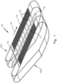
- a transport device 10 designed as an endless, belt-shaped system is shown, which in an upper section 10.1 runs horizontally through a device for the heat treatment of workpieces, not shown here. In a lower section 10.2, it runs back outside the device for the heat treatment.
- the transport device 10 is formed by two lateral link belts 11, 12 and rods 13 connecting them to one another and aligned transversely to the transport direction 14.
- the mutual distance d between the rods 13 is relatively large. It only has to be small enough for a workpiece (not shown here) to rest on at least two of the rods 13 . Hot air can therefore flow undisturbed against the workpiece from below through the space between the bars 13 .
- the lateral link belts 11, 12 are formed by a large number of links 15, 16 arranged next to one another and one behind the other and are driven in a manner which is not illustrated in detail here.
- the ends of the rods 13 are either freely rotatably mounted in the lateral link belts 11, 12 or fixed to the link belts 11, 12. This can be designed differently depending on the weight and size of the workpieces and the desired transport speed.
- the rods 13 are freely rotatable and rest on a rail 15. They can thus roll on the rail 15 and transport a workpiece lying on them at a speed that is significantly higher than the speed of the link belts 11, 12.
- the rods 13 can also protrude above the link belts 11, 12, so that even wide workpieces only rest on the rods 13 in order to optimize the air circulation on the underside of the workpieces.
Landscapes
- Engineering & Computer Science (AREA)
- Mechanical Engineering (AREA)
- Processing And Handling Of Plastics And Other Materials For Molding In General (AREA)
- Treatment Of Fiber Materials (AREA)
Description
Zum Durchlauftransport von Werkstücken durch Öfen oder Schrumpftunnel für folienverpackte Gegenstände oder andere Anlagen, bei denen es darauf ankommt, dass die Unterseite der Werkstücke ebenfalls erwärmt wird, werden häufig Transportvorrichtungen mit zwei seitlichen Rollenketten, zwischen denen Stäbe angeordnet sind, verwendet.For the continuous transport of workpieces through ovens or shrink tunnels for foil-wrapped objects or other systems in which it is important that the underside of the workpieces is also heated, transport devices with two lateral roller chains between which rods are arranged are often used.
Eine solche Transportvorrichtung ist beispielsweise in der
Das Werkstück wird auf den Stäben liegend durch den Ofen oder Schrumpftunnel bewegt. Durch den Zwischenraum zwischen den Stäben kann warme oder heiße Luft ungehindert hindurchströmen, auch wenn das Werkstück sehr schnell durch den Ofen oder Schrumpftunnel bewegt wird. Nachteilig ist allerdings, dass die Rollenketten dauergeschmiert werden müssen.The workpiece is moved through the oven or shrink tunnel lying on the bars. The space between the bars allows warm or hot air to flow unhindered, even when the workpiece is being moved through the oven or shrink tunnel at high speed. The disadvantage, however, is that the roller chains have to be permanently lubricated.
Aus der
Der vorliegenden Erfindung liegt die Aufgabe zugrunde, eine wartungsarme Transportvorrichtung bereitzustellen, mit der Werkstücke durch Öfen oder dergleichen hindurchbewegbar sind und die sicherstellt, dass auch die Unterseite der Werkstücke ausreichend erwärmt wird.The object of the present invention is to provide a low-maintenance transport device with which workpieces can be moved through ovens or the like and which ensures that the underside of the workpieces is also sufficiently heated.
Die Aufgabe wird gelöst durch eine Transportvorrichtung mit den Merkmalen des Anspruchs 1. Die Werkstücke können je nach Größe entweder nur auf den Stäben oder auf den Stäben und den Gliederbändern aufliegen. Durch den relativ großen Abstand zwischen den Stäben kann ungehindert Wärme zur Unterseite der Werkstücke dringen, auch wenn diese schnell durch die Vorrichtung bewegt werden. Die angetriebenen Gliederbänder können wartungsarm oder sogar vollständig wartungsfrei gestaltet werden, da sie aus Kunststoff gefertigt sind, der vorzugsweise hitzebeständig ist. Die erfindungsgemäße Transportvorrichtung erfüllt somit alle aufgabengemäßen Anforderungen.The object is achieved by a transport device with the features of
Die Enden der Stäbe können entweder fest mit den Gliederbändern verbunden sein oder frei drehbar in diesen gelagert sein. Frei drehbare Stäbe erlauben das Zuführen der Werkstücke mit beliebiger Geschwindigkeit. Für leichtere Werkstücke mit einer glatten Oberfläche sowie hohen Transportgeschwindigkeiten können dagegen feststehende Stäbe vorteilhafter sein, um eine Relativbewegung zwischen Werkstücken und Transportvorrichtung während des Transports zu verhindern.The ends of the rods can either be fixed to the link belts or be freely rotatable in them. Freely rotatable rods allow the workpieces to be fed in at any speed. For lighter workpieces with a smooth surface and high transport speeds, on the other hand, fixed bars can be more advantageous in order to prevent relative movement between the workpieces and the transport device during transport.
Werden die Stäbe frei drehbar ausgeführt, so können sie auf einer Schiene aufliegen und auf dieser abrollen. Werkstücke, die nur auf den Stäben aufliegen, können dadurch mit der doppelten Geschwindigkeit wie die Gliederbänder durch die Vorrichtung zur Hitzebehandlung bewegt werden. Außerdem liegen die Werkstücke dann nicht immer an den gleichen Stellen auf den Stäben auf, sodass die gesamte Unterseite des Werkstücks gleichmäßig der Hitze ausgesetzt werden kann.If the rods are designed to be freely rotatable, they can rest on a rail and roll off it. Workpieces that only rest on the rods can be moved through the heat treatment device at twice the speed of the link belts. In addition, the workpieces are not always in the same place on the rods, so that the entire underside of the workpiece can be exposed to the heat evenly.
Je nach den Maßen und dem Gewicht der Werkstücke und der gewünschten Transportgeschwindigkeit können die Gliederbänder zusammen 20 % bis 50 % der Breite der Transportvorrichtung einnehmen.Depending on the dimensions and weight of the workpieces and the desired transport speed, the chain conveyors together can take up 20% to 50% of the width of the transport device.
Weitere Vorteile ergeben sich, wenn die Gliederbänder als Endlosbänder ausgeführt sind. Die Transportvorrichtung läuft somit vom Ende der Vorrichtung zur Hitzebehandlung des Werkstücks wieder zurück zum Eingang der Vorrichtung. Auf diesem Weg außerhalb der Vorrichtung können die Gliederbänder und Stäbe ausreichend abkühlen.Further advantages arise when the link belts are designed as endless belts. The transport device thus runs from the end of the device for heat treatment of the workpiece back to the entrance of the device. In this way outside of the device, the link belts and rods can cool down sufficiently.
Insbesondere für den Transport breiter Werkstücke ist es vorteilhaft, dass die Stäbe in der Höhe über die Gliederbänder überstehen. Die Werkstücke liegen nur auf den Stäben auf und nicht auch auf den Gliederbändern. Die Glieder der Bänder behindern dadurch die Zirkulation von warmer Luft auf der Unterseite des Werkstücks nicht.When transporting wide workpieces in particular, it is advantageous that the height of the bars protrudes over the link belts. The workpieces only rest on the bars and not on the link belts. As a result, the links of the belts do not impede the circulation of warm air on the underside of the workpiece.
Die Transportvorrichtung kann vorzugsweise so ausgelegt sein, dass sie mit Geschwindigkeiten von mehr als 40 m/min durch die Vorrichtung zur Hitzeeinwirkung hindurchbewegbar ist. Dadurch ist eine rationelle Wärmebehandlung einer Vielzahl von Werkstücken möglich.The transport device can preferably be designed in such a way that it can be moved through the heat application device at speeds in excess of 40 m/min. This enables efficient heat treatment of a large number of workpieces.
Die Transportvorrichtung ist für verschiedene Anwendungen einsetzbar. Mit der Transportvorrichtung können aber insbesondere folienverpackte Gegenstände durch einen Schrumpftunnel transportierbar sein. Die Gegenstände werden im Schrumpftunnel auch von unten mit heißer Luft beaufschlagt. Um ein gutes und gleichmäßiges Schrumpfergebnis der Folie auch auf der Unterseite des Werkstücks zu erreichen, ist es notwendig, dass die heiße Luft die Folie auf der Auflageseite des Werkstücks ungehindert erreichen kann. Dies ist bei der erfindungsgemäßen Vorrichtung durch die großen Abstände zwischen den Stäben selbst bei hohen Transportgeschwindigkeiten gewährleistet. Gleichzeitig sorgen die angetriebenen seitlichen Gliederbänder dafür, dass die Transportvorrichtung wartungsfrei ist. Ein weiterer Vorteil der relativ weit beabstandeten Stäbe besteht darin, dass diese sich auf ihrem Rückweg zwischen dem Ende des Schrumpftunnels und dem Eingang des Schrumpftunnels schneller wieder abkühlen als die mit einer Vielzahl von Gliedern versehenen Gliederbänder. Die Gefahr eines Anhaftens der Folie an der Transportvorrichtung ist dadurch geringer als bei Transportvorrichtungen, die nur aus einem Gliederband bestehen.The transport device can be used for various applications. With the transport device, however, in particular foil-packaged objects can be transported through a shrink tunnel. In the shrink tunnel, the objects are also subjected to hot air from below. In order to achieve a good and even shrinking result for the film on the underside of the workpiece, it is necessary for the hot air to be able to reach the film on the supporting side of the workpiece unhindered. With the device according to the invention, this is ensured by the large distances between the rods, even at high transport speeds. At the same time, the driven link belts on the side ensure that the transport device is maintenance-free. A further advantage of the relatively widely spaced rods is that they cool down more quickly on their way back between the end of the shrink tunnel and the entrance of the shrink tunnel than the link belts provided with a large number of links. As a result, the risk of the film sticking to the transport device is lower than with transport devices that only consist of a link belt.
Die erfindungsgemäße Transportvorrichtung kann daher durch Vorrichtungen zur Hitzebehandlung mit Temperaturen von mehr als 180°C hindurchbewegt werden.The transport device according to the invention can therefore be passed through heat treatment devices with temperatures in excess of 180°C.
Nachfolgend wird ein bevorzugtes Ausführungsbeispiel einer erfindungsgemäßen Transportvorrichtung anhand der Zeichnung detailliert beschrieben.A preferred exemplary embodiment of a transport device according to the invention is described in detail below with reference to the drawing.
Es zeigen:
- Fig. 1
- eine perspektivische Ansicht einer erfindungsgemäßen Transportvorrichtung;
- Fig. 2
- einen vergrößerten Ausschnitt der Transportvorrichtung aus
Fig. 1 .
- 1
- a perspective view of a transport device according to the invention;
- 2
- an enlarged section of the
transport device 1 .
In
Die Transportvorrichtung 10 wird dabei von zwei seitlichen Gliederbändern 11, 12 und diese miteinander verbindenden und quer zur Transportrichtung 14 ausgerichteten Stäben 13 gebildet.The
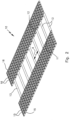
Dieser Aufbau ist in der Detaildarstellung in
Im dargestellten Beispiel in
Die Stäbe 13 können außerdem in der Höhe über die Gliederbänder 11, 12 überstehen, sodass auch breite Werkstücke nur auf den Stäben 13 aufliegen, um die Luftzirkulation auf der Unterseite der Werkstücke zu optimieren.The
Claims (8)
- Transport device for transporting workpieces through devices for the heat treatment of the workpieces, said device comprising two maintenance- and lubrication-free link belts (11, 12) arranged laterally in the transport plane,
characterized in that the link belts (11, 12) are connected to one another by rods (13) extending transversely to the transport direction (14), the rods (13) protruding in height above the link belts (11, 12), the link belts (11, 12) being made of plastics material. - Transport device according to claim 1, characterized in that the ends of the rods (13) are rigidly connected to the link belts (11, 12) or are mounted freely rotatably therein.
- Transport device according to claim 2, characterized in that the freely rotatable rods (13) rest on a rail (15) and roll thereon.
- Transport device according to any of the preceding claims,
characterized in that the link belts (11, 12) together occupy 20% to 50% of the width of the transport device (10). - Transport device according to any of the preceding claims,
characterized in that the link belts (11, 12) are designed as continuous belts. - Transport device according to any of the preceding claims,
characterized in that film-packaged objects can be transported through a shrink tunnel by means of the transport device (10). - Transport device according to any of the preceding claims,
characterized in that it can be moved at speeds of more than 40 m/min through the device for heat application. - Transport device according to any of the preceding claims,
characterized in that it can be moved through devices for heat treatment at temperatures of more than 180°C.
Applications Claiming Priority (1)
| Application Number | Priority Date | Filing Date | Title |
|---|---|---|---|
| DE102015105660.7A DE102015105660A1 (en) | 2015-04-14 | 2015-04-14 | transport device |
Publications (3)
| Publication Number | Publication Date |
|---|---|
| EP3081499A1 EP3081499A1 (en) | 2016-10-19 |
| EP3081499B1 EP3081499B1 (en) | 2017-10-18 |
| EP3081499B2 true EP3081499B2 (en) | 2023-02-08 |
Family
ID=55589667
Family Applications (1)
| Application Number | Title | Priority Date | Filing Date |
|---|---|---|---|
| EP16160121.6A Active EP3081499B2 (en) | 2015-04-14 | 2016-03-14 | Transport device |
Country Status (2)
| Country | Link |
|---|---|
| EP (1) | EP3081499B2 (en) |
| DE (1) | DE102015105660A1 (en) |
Families Citing this family (2)
| Publication number | Priority date | Publication date | Assignee | Title |
|---|---|---|---|---|
| DE102017103539B3 (en) | 2017-02-21 | 2018-07-26 | BVM Brunner GmbH & Co. KG | Transport device with sliding chain |
| DE102018117842A1 (en) * | 2018-07-24 | 2020-01-30 | Khs Gmbh | Shrink tunnel for shrinking shrink films onto packaging or packaging units |
Citations (16)
| Publication number | Priority date | Publication date | Assignee | Title |
|---|---|---|---|---|
| GB834002A (en) † | 1955-09-26 | 1960-05-04 | T & T Vicars Ltd | Improvements in or relating to conveyors |
| GB1097389A (en) † | 1965-10-01 | 1968-01-03 | Lerner Machine Company Ltd | Improvements in or relating to conveyor systems |
| DE6930237U (en) † | 1969-07-30 | 1969-11-27 | Maschb Aachen Fuerstenau Ges M | SUPPORTING ROD FOR COLLARS SHRINKING FILM DEVICES |
| US3597852A (en) † | 1970-01-02 | 1971-08-10 | Deering Milliken Res Corp | Coin conveyor and shrink oven |
| DE2011137A1 (en) † | 1970-03-10 | 1971-11-25 | Nordischer Maschinenbau, Rud. Baader, 2400 Lübeck | Shrink and cooling tunnel for stacks of newspapers |
| DE2212726A1 (en) † | 1972-03-16 | 1973-09-20 | Fischer & Co Kg H | METHOD AND DEVICE FOR TUNNEL CONTINUOUS HEATING OF MATERIALS, IN PARTICULAR STRAND-SHAPED PRODUCTS, COVERED WITH SHRINK FILM |
| DE2520428A1 (en) † | 1975-05-07 | 1976-11-25 | Beck & Co Packautomaten | Advance unit for packaged goods - uses engaging pressure rail to control advance speed through foil shrinking tunnel |
| DE3307054A1 (en) † | 1983-03-01 | 1984-09-06 | Agfa-Gevaert Ag, 5090 Leverkusen | Rod-type chain conveyor in shrinkage tunnel |
| DE3540403A1 (en) † | 1985-11-14 | 1987-05-21 | Hermann Schlauch | Packaging machine |
| DE4015118A1 (en) † | 1990-05-11 | 1991-11-14 | Jonge Poerink Bv | CONVEYOR BAND |
| US5271491A (en) † | 1993-02-18 | 1993-12-21 | Guy Irwin | Bi-directional short radius turn conveyor belt |
| EP0752380A1 (en) † | 1995-07-07 | 1997-01-08 | SMI SISTEMI MACCHINE IMPIANTI S.r.l. | Conveyor device for thermoshrinking film packaging systems |
| US20010025771A1 (en) † | 1998-12-21 | 2001-10-04 | Stebnicki James C. | Fiber filled chain link for a modular conveyer chain |
| WO2009038807A1 (en) † | 2007-09-21 | 2009-03-26 | Cambridge International, Inc. | Flat wire conveyor belt system |
| US20090111632A1 (en) † | 2007-10-31 | 2009-04-30 | Habasit Ag | Hybrid mesh belt |
| EP2565123A1 (en) † | 2011-09-02 | 2013-03-06 | Dalli-Werke GmbH & Co. KG. | Device for processing products encased in film |
Family Cites Families (3)
| Publication number | Priority date | Publication date | Assignee | Title |
|---|---|---|---|---|
| CA775339A (en) * | 1968-01-09 | Zelnick Seymour | Apparatus for shrinking films on packages | |
| DE1876453U (en) * | 1963-04-20 | 1963-07-25 | Kalle Ag | THROUGH HEAT CHANNEL FOR SHRINKING PACKAGING. |
| US3309835A (en) * | 1964-01-23 | 1967-03-21 | Diamond Int Corp | Method and apparatus for producing packages with a heat-shrink film |
-
2015
- 2015-04-14 DE DE102015105660.7A patent/DE102015105660A1/en not_active Withdrawn
-
2016
- 2016-03-14 EP EP16160121.6A patent/EP3081499B2/en active Active
Patent Citations (17)
| Publication number | Priority date | Publication date | Assignee | Title |
|---|---|---|---|---|
| GB834002A (en) † | 1955-09-26 | 1960-05-04 | T & T Vicars Ltd | Improvements in or relating to conveyors |
| GB1097389A (en) † | 1965-10-01 | 1968-01-03 | Lerner Machine Company Ltd | Improvements in or relating to conveyor systems |
| DE6930237U (en) † | 1969-07-30 | 1969-11-27 | Maschb Aachen Fuerstenau Ges M | SUPPORTING ROD FOR COLLARS SHRINKING FILM DEVICES |
| US3597852A (en) † | 1970-01-02 | 1971-08-10 | Deering Milliken Res Corp | Coin conveyor and shrink oven |
| DE2011137A1 (en) † | 1970-03-10 | 1971-11-25 | Nordischer Maschinenbau, Rud. Baader, 2400 Lübeck | Shrink and cooling tunnel for stacks of newspapers |
| DE2212726A1 (en) † | 1972-03-16 | 1973-09-20 | Fischer & Co Kg H | METHOD AND DEVICE FOR TUNNEL CONTINUOUS HEATING OF MATERIALS, IN PARTICULAR STRAND-SHAPED PRODUCTS, COVERED WITH SHRINK FILM |
| DE2520428A1 (en) † | 1975-05-07 | 1976-11-25 | Beck & Co Packautomaten | Advance unit for packaged goods - uses engaging pressure rail to control advance speed through foil shrinking tunnel |
| DE3307054A1 (en) † | 1983-03-01 | 1984-09-06 | Agfa-Gevaert Ag, 5090 Leverkusen | Rod-type chain conveyor in shrinkage tunnel |
| DE3540403A1 (en) † | 1985-11-14 | 1987-05-21 | Hermann Schlauch | Packaging machine |
| DE4015118A1 (en) † | 1990-05-11 | 1991-11-14 | Jonge Poerink Bv | CONVEYOR BAND |
| US5271491A (en) † | 1993-02-18 | 1993-12-21 | Guy Irwin | Bi-directional short radius turn conveyor belt |
| EP0752380A1 (en) † | 1995-07-07 | 1997-01-08 | SMI SISTEMI MACCHINE IMPIANTI S.r.l. | Conveyor device for thermoshrinking film packaging systems |
| US20010025771A1 (en) † | 1998-12-21 | 2001-10-04 | Stebnicki James C. | Fiber filled chain link for a modular conveyer chain |
| WO2009038807A1 (en) † | 2007-09-21 | 2009-03-26 | Cambridge International, Inc. | Flat wire conveyor belt system |
| US20090111632A1 (en) † | 2007-10-31 | 2009-04-30 | Habasit Ag | Hybrid mesh belt |
| WO2009055950A1 (en) † | 2007-10-31 | 2009-05-07 | Habasit Ag | Hybrid mesh belt |
| EP2565123A1 (en) † | 2011-09-02 | 2013-03-06 | Dalli-Werke GmbH & Co. KG. | Device for processing products encased in film |
Also Published As
| Publication number | Publication date |
|---|---|
| EP3081499A1 (en) | 2016-10-19 |
| EP3081499B1 (en) | 2017-10-18 |
| DE102015105660A1 (en) | 2016-10-20 |
Similar Documents
| Publication | Publication Date | Title |
|---|---|---|
| DE60106099T2 (en) | Support rail for the curved section of a monorail | |
| DE102014103711A1 (en) | Deflection device for objects and methods for deflecting objects | |
| EP3081499B2 (en) | Transport device | |
| DE69008113T2 (en) | Device for conveying grain. | |
| CH636061A5 (en) | DEVICE FOR THE STORAGE DEPOSIT OF INDIVIDUALLY REQUIRED BENDING FILMS. | |
| DE102012104891B4 (en) | Multi-section conveyor belt with rollers | |
| EP3031752A1 (en) | Conveyor chain link, conveyor chain and a transfer and/or storage system for rod-like articles of the tobacco industry | |
| DE1506905A1 (en) | Conveyor device with rollers | |
| DE202016008538U1 (en) | Device for transporting objects, in particular glass articles | |
| DE102013107612A1 (en) | conveyor | |
| DE2717784C3 (en) | Trolley for fittings, tiles or other ceramic products in a tunnel kiln | |
| EP3314035B1 (en) | Conveyor device for a substrate | |
| DE2146554B2 (en) | Method and device for long rolling and / or long working of dough pieces | |
| DE10340867A1 (en) | Conveyor system, in particular an airport baggage conveyor system, and guide means for such a conveyor system | |
| DE102017130159B4 (en) | Disposal of unpressed material in a press for the continuous production of material plates | |
| EP3064454B1 (en) | Conveyor chain for transporting items and transport system with conveyor chain | |
| DE102017103539B3 (en) | Transport device with sliding chain | |
| DE202014002923U1 (en) | Sorting device for piece goods | |
| DE102010046197A1 (en) | Device for conveying pallets | |
| AT517875A2 (en) | Picking device and picking warehouse | |
| EP3044132B1 (en) | Conveying system | |
| DE102015011483B4 (en) | Drive for conveyor systems | |
| DE10211216B4 (en) | Plant for double-sided treatment of sheet metal blanks | |
| EP2996092A1 (en) | Device for collecting empty containers | |
| DE2045802A1 (en) | Method and device for transporting heavy or bulky objects |
Legal Events
| Date | Code | Title | Description |
|---|---|---|---|
| PUAI | Public reference made under article 153(3) epc to a published international application that has entered the european phase |
Free format text: ORIGINAL CODE: 0009012 |
|
| AK | Designated contracting states |
Kind code of ref document: A1 Designated state(s): AL AT BE BG CH CY CZ DE DK EE ES FI FR GB GR HR HU IE IS IT LI LT LU LV MC MK MT NL NO PL PT RO RS SE SI SK SM TR |
|
| AX | Request for extension of the european patent |
Extension state: BA ME |
|
| STAA | Information on the status of an ep patent application or granted ep patent |
Free format text: STATUS: REQUEST FOR EXAMINATION WAS MADE |
|
| 17P | Request for examination filed |
Effective date: 20170329 |
|
| RBV | Designated contracting states (corrected) |
Designated state(s): AL AT BE BG CH CY CZ DE DK EE ES FI FR GB GR HR HU IE IS IT LI LT LU LV MC MK MT NL NO PL PT RO RS SE SI SK SM TR |
|
| GRAP | Despatch of communication of intention to grant a patent |
Free format text: ORIGINAL CODE: EPIDOSNIGR1 |
|
| STAA | Information on the status of an ep patent application or granted ep patent |
Free format text: STATUS: GRANT OF PATENT IS INTENDED |
|
| RIC1 | Information provided on ipc code assigned before grant |
Ipc: B65G 17/00 20060101ALI20170421BHEP Ipc: B65B 53/06 20060101AFI20170421BHEP |
|
| INTG | Intention to grant announced |
Effective date: 20170515 |
|
| GRAS | Grant fee paid |
Free format text: ORIGINAL CODE: EPIDOSNIGR3 |
|
| GRAA | (expected) grant |
Free format text: ORIGINAL CODE: 0009210 |
|
| STAA | Information on the status of an ep patent application or granted ep patent |
Free format text: STATUS: THE PATENT HAS BEEN GRANTED |
|
| AK | Designated contracting states |
Kind code of ref document: B1 Designated state(s): AL AT BE BG CH CY CZ DE DK EE ES FI FR GB GR HR HU IE IS IT LI LT LU LV MC MK MT NL NO PL PT RO RS SE SI SK SM TR |
|
| REG | Reference to a national code |
Ref country code: GB Ref legal event code: FG4D Free format text: NOT ENGLISH |
|
| REG | Reference to a national code |
Ref country code: CH Ref legal event code: EP |
|
| REG | Reference to a national code |
Ref country code: AT Ref legal event code: REF Ref document number: 937707 Country of ref document: AT Kind code of ref document: T Effective date: 20171115 Ref country code: IE Ref legal event code: FG4D Free format text: LANGUAGE OF EP DOCUMENT: GERMAN |
|
| REG | Reference to a national code |
Ref country code: DE Ref legal event code: R096 Ref document number: 502016000212 Country of ref document: DE |
|
| REG | Reference to a national code |
Ref country code: NL Ref legal event code: MP Effective date: 20171018 |
|
| REG | Reference to a national code |
Ref country code: LT Ref legal event code: MG4D |
|
| PG25 | Lapsed in a contracting state [announced via postgrant information from national office to epo] |
Ref country code: NL Free format text: LAPSE BECAUSE OF FAILURE TO SUBMIT A TRANSLATION OF THE DESCRIPTION OR TO PAY THE FEE WITHIN THE PRESCRIBED TIME-LIMIT Effective date: 20171018 |
|
| PG25 | Lapsed in a contracting state [announced via postgrant information from national office to epo] |
Ref country code: FI Free format text: LAPSE BECAUSE OF FAILURE TO SUBMIT A TRANSLATION OF THE DESCRIPTION OR TO PAY THE FEE WITHIN THE PRESCRIBED TIME-LIMIT Effective date: 20171018 Ref country code: LT Free format text: LAPSE BECAUSE OF FAILURE TO SUBMIT A TRANSLATION OF THE DESCRIPTION OR TO PAY THE FEE WITHIN THE PRESCRIBED TIME-LIMIT Effective date: 20171018 Ref country code: SE Free format text: LAPSE BECAUSE OF FAILURE TO SUBMIT A TRANSLATION OF THE DESCRIPTION OR TO PAY THE FEE WITHIN THE PRESCRIBED TIME-LIMIT Effective date: 20171018 Ref country code: NO Free format text: LAPSE BECAUSE OF FAILURE TO SUBMIT A TRANSLATION OF THE DESCRIPTION OR TO PAY THE FEE WITHIN THE PRESCRIBED TIME-LIMIT Effective date: 20180118 Ref country code: ES Free format text: LAPSE BECAUSE OF FAILURE TO SUBMIT A TRANSLATION OF THE DESCRIPTION OR TO PAY THE FEE WITHIN THE PRESCRIBED TIME-LIMIT Effective date: 20171018 |
|
| PG25 | Lapsed in a contracting state [announced via postgrant information from national office to epo] |
Ref country code: RS Free format text: LAPSE BECAUSE OF FAILURE TO SUBMIT A TRANSLATION OF THE DESCRIPTION OR TO PAY THE FEE WITHIN THE PRESCRIBED TIME-LIMIT Effective date: 20171018 Ref country code: BG Free format text: LAPSE BECAUSE OF FAILURE TO SUBMIT A TRANSLATION OF THE DESCRIPTION OR TO PAY THE FEE WITHIN THE PRESCRIBED TIME-LIMIT Effective date: 20180118 Ref country code: LV Free format text: LAPSE BECAUSE OF FAILURE TO SUBMIT A TRANSLATION OF THE DESCRIPTION OR TO PAY THE FEE WITHIN THE PRESCRIBED TIME-LIMIT Effective date: 20171018 Ref country code: IS Free format text: LAPSE BECAUSE OF FAILURE TO SUBMIT A TRANSLATION OF THE DESCRIPTION OR TO PAY THE FEE WITHIN THE PRESCRIBED TIME-LIMIT Effective date: 20180218 Ref country code: HR Free format text: LAPSE BECAUSE OF FAILURE TO SUBMIT A TRANSLATION OF THE DESCRIPTION OR TO PAY THE FEE WITHIN THE PRESCRIBED TIME-LIMIT Effective date: 20171018 Ref country code: GR Free format text: LAPSE BECAUSE OF FAILURE TO SUBMIT A TRANSLATION OF THE DESCRIPTION OR TO PAY THE FEE WITHIN THE PRESCRIBED TIME-LIMIT Effective date: 20180119 |
|
| REG | Reference to a national code |
Ref country code: DE Ref legal event code: R026 Ref document number: 502016000212 Country of ref document: DE |
|
| PLBI | Opposition filed |
Free format text: ORIGINAL CODE: 0009260 |
|
| PLAX | Notice of opposition and request to file observation + time limit sent |
Free format text: ORIGINAL CODE: EPIDOSNOBS2 |
|
| PG25 | Lapsed in a contracting state [announced via postgrant information from national office to epo] |
Ref country code: DK Free format text: LAPSE BECAUSE OF FAILURE TO SUBMIT A TRANSLATION OF THE DESCRIPTION OR TO PAY THE FEE WITHIN THE PRESCRIBED TIME-LIMIT Effective date: 20171018 Ref country code: EE Free format text: LAPSE BECAUSE OF FAILURE TO SUBMIT A TRANSLATION OF THE DESCRIPTION OR TO PAY THE FEE WITHIN THE PRESCRIBED TIME-LIMIT Effective date: 20171018 Ref country code: SK Free format text: LAPSE BECAUSE OF FAILURE TO SUBMIT A TRANSLATION OF THE DESCRIPTION OR TO PAY THE FEE WITHIN THE PRESCRIBED TIME-LIMIT Effective date: 20171018 Ref country code: CZ Free format text: LAPSE BECAUSE OF FAILURE TO SUBMIT A TRANSLATION OF THE DESCRIPTION OR TO PAY THE FEE WITHIN THE PRESCRIBED TIME-LIMIT Effective date: 20171018 |
|
| 26 | Opposition filed |
Opponent name: BECK PACKAUTOMATEN GMBH CO. KG Effective date: 20180713 |
|
| PG25 | Lapsed in a contracting state [announced via postgrant information from national office to epo] |
Ref country code: SM Free format text: LAPSE BECAUSE OF FAILURE TO SUBMIT A TRANSLATION OF THE DESCRIPTION OR TO PAY THE FEE WITHIN THE PRESCRIBED TIME-LIMIT Effective date: 20171018 Ref country code: IT Free format text: LAPSE BECAUSE OF FAILURE TO SUBMIT A TRANSLATION OF THE DESCRIPTION OR TO PAY THE FEE WITHIN THE PRESCRIBED TIME-LIMIT Effective date: 20171018 Ref country code: PL Free format text: LAPSE BECAUSE OF FAILURE TO SUBMIT A TRANSLATION OF THE DESCRIPTION OR TO PAY THE FEE WITHIN THE PRESCRIBED TIME-LIMIT Effective date: 20171018 |
|
| PG25 | Lapsed in a contracting state [announced via postgrant information from national office to epo] |
Ref country code: MT Free format text: LAPSE BECAUSE OF FAILURE TO SUBMIT A TRANSLATION OF THE DESCRIPTION OR TO PAY THE FEE WITHIN THE PRESCRIBED TIME-LIMIT Effective date: 20171018 |
|
| PLBB | Reply of patent proprietor to notice(s) of opposition received |
Free format text: ORIGINAL CODE: EPIDOSNOBS3 |
|
| PG25 | Lapsed in a contracting state [announced via postgrant information from national office to epo] |
Ref country code: MC Free format text: LAPSE BECAUSE OF FAILURE TO SUBMIT A TRANSLATION OF THE DESCRIPTION OR TO PAY THE FEE WITHIN THE PRESCRIBED TIME-LIMIT Effective date: 20171018 Ref country code: SI Free format text: LAPSE BECAUSE OF FAILURE TO SUBMIT A TRANSLATION OF THE DESCRIPTION OR TO PAY THE FEE WITHIN THE PRESCRIBED TIME-LIMIT Effective date: 20171018 |
|
| REG | Reference to a national code |
Ref country code: BE Ref legal event code: MM Effective date: 20180331 |
|
| REG | Reference to a national code |
Ref country code: IE Ref legal event code: MM4A |
|
| PG25 | Lapsed in a contracting state [announced via postgrant information from national office to epo] |
Ref country code: LU Free format text: LAPSE BECAUSE OF NON-PAYMENT OF DUE FEES Effective date: 20180314 |
|
| PG25 | Lapsed in a contracting state [announced via postgrant information from national office to epo] |
Ref country code: IE Free format text: LAPSE BECAUSE OF NON-PAYMENT OF DUE FEES Effective date: 20180314 |
|
| PG25 | Lapsed in a contracting state [announced via postgrant information from national office to epo] |
Ref country code: BE Free format text: LAPSE BECAUSE OF NON-PAYMENT OF DUE FEES Effective date: 20180331 |
|
| PG25 | Lapsed in a contracting state [announced via postgrant information from national office to epo] |
Ref country code: FR Free format text: LAPSE BECAUSE OF NON-PAYMENT OF DUE FEES Effective date: 20180331 |
|
| REG | Reference to a national code |
Ref country code: CH Ref legal event code: PL |
|
| PG25 | Lapsed in a contracting state [announced via postgrant information from national office to epo] |
Ref country code: CH Free format text: LAPSE BECAUSE OF NON-PAYMENT OF DUE FEES Effective date: 20190331 Ref country code: LI Free format text: LAPSE BECAUSE OF NON-PAYMENT OF DUE FEES Effective date: 20190331 |
|
| APBM | Appeal reference recorded |
Free format text: ORIGINAL CODE: EPIDOSNREFNO |
|
| APBP | Date of receipt of notice of appeal recorded |
Free format text: ORIGINAL CODE: EPIDOSNNOA2O |
|
| APAH | Appeal reference modified |
Free format text: ORIGINAL CODE: EPIDOSCREFNO |
|
| PG25 | Lapsed in a contracting state [announced via postgrant information from national office to epo] |
Ref country code: TR Free format text: LAPSE BECAUSE OF FAILURE TO SUBMIT A TRANSLATION OF THE DESCRIPTION OR TO PAY THE FEE WITHIN THE PRESCRIBED TIME-LIMIT Effective date: 20171018 |
|
| APBQ | Date of receipt of statement of grounds of appeal recorded |
Free format text: ORIGINAL CODE: EPIDOSNNOA3O |
|
| PG25 | Lapsed in a contracting state [announced via postgrant information from national office to epo] |
Ref country code: PT Free format text: LAPSE BECAUSE OF FAILURE TO SUBMIT A TRANSLATION OF THE DESCRIPTION OR TO PAY THE FEE WITHIN THE PRESCRIBED TIME-LIMIT Effective date: 20171018 |
|
| PG25 | Lapsed in a contracting state [announced via postgrant information from national office to epo] |
Ref country code: MK Free format text: LAPSE BECAUSE OF NON-PAYMENT OF DUE FEES Effective date: 20171018 Ref country code: CY Free format text: LAPSE BECAUSE OF FAILURE TO SUBMIT A TRANSLATION OF THE DESCRIPTION OR TO PAY THE FEE WITHIN THE PRESCRIBED TIME-LIMIT Effective date: 20171018 Ref country code: HU Free format text: LAPSE BECAUSE OF FAILURE TO SUBMIT A TRANSLATION OF THE DESCRIPTION OR TO PAY THE FEE WITHIN THE PRESCRIBED TIME-LIMIT; INVALID AB INITIO Effective date: 20160314 Ref country code: RO Free format text: LAPSE BECAUSE OF FAILURE TO SUBMIT A TRANSLATION OF THE DESCRIPTION OR TO PAY THE FEE WITHIN THE PRESCRIBED TIME-LIMIT Effective date: 20171018 |
|
| PG25 | Lapsed in a contracting state [announced via postgrant information from national office to epo] |
Ref country code: AL Free format text: LAPSE BECAUSE OF FAILURE TO SUBMIT A TRANSLATION OF THE DESCRIPTION OR TO PAY THE FEE WITHIN THE PRESCRIBED TIME-LIMIT Effective date: 20171018 |
|
| GBPC | Gb: european patent ceased through non-payment of renewal fee |
Effective date: 20200314 |
|
| PG25 | Lapsed in a contracting state [announced via postgrant information from national office to epo] |
Ref country code: GB Free format text: LAPSE BECAUSE OF NON-PAYMENT OF DUE FEES Effective date: 20200314 |
|
| REG | Reference to a national code |
Ref country code: AT Ref legal event code: MM01 Ref document number: 937707 Country of ref document: AT Kind code of ref document: T Effective date: 20210314 |
|
| APBU | Appeal procedure closed |
Free format text: ORIGINAL CODE: EPIDOSNNOA9O |
|
| PG25 | Lapsed in a contracting state [announced via postgrant information from national office to epo] |
Ref country code: AT Free format text: LAPSE BECAUSE OF NON-PAYMENT OF DUE FEES Effective date: 20210314 |
|
| PUAH | Patent maintained in amended form |
Free format text: ORIGINAL CODE: 0009272 |
|
| STAA | Information on the status of an ep patent application or granted ep patent |
Free format text: STATUS: PATENT MAINTAINED AS AMENDED |
|
| 27A | Patent maintained in amended form |
Effective date: 20230208 |
|
| AK | Designated contracting states |
Kind code of ref document: B2 Designated state(s): AL AT BE BG CH CY CZ DE DK EE ES FI FR GB GR HR HU IE IS IT LI LT LU LV MC MK MT NL NO PL PT RO RS SE SI SK SM TR |
|
| REG | Reference to a national code |
Ref country code: DE Ref legal event code: R102 Ref document number: 502016000212 Country of ref document: DE |
|
| PGFP | Annual fee paid to national office [announced via postgrant information from national office to epo] |
Ref country code: DE Payment date: 20240325 Year of fee payment: 9 |