EP3081452A1 - Self-propelled carriage using spherical drive module - Google Patents
Self-propelled carriage using spherical drive module Download PDFInfo
- Publication number
- EP3081452A1 EP3081452A1 EP14869883.0A EP14869883A EP3081452A1 EP 3081452 A1 EP3081452 A1 EP 3081452A1 EP 14869883 A EP14869883 A EP 14869883A EP 3081452 A1 EP3081452 A1 EP 3081452A1
- Authority
- EP
- European Patent Office
- Prior art keywords
- uncontrolled
- spherical
- spherical body
- drive wheel
- self
- Prior art date
- Legal status (The legal status is an assumption and is not a legal conclusion. Google has not performed a legal analysis and makes no representation as to the accuracy of the status listed.)
- Granted
Links
Images


Classifications
-
- B—PERFORMING OPERATIONS; TRANSPORTING
- B60—VEHICLES IN GENERAL
- B60B—VEHICLE WHEELS; CASTORS; AXLES FOR WHEELS OR CASTORS; INCREASING WHEEL ADHESION
- B60B33/00—Castors in general ; Anti-clogging castors
- B60B33/08—Ball castors
-
- B—PERFORMING OPERATIONS; TRANSPORTING
- B60—VEHICLES IN GENERAL
- B60B—VEHICLE WHEELS; CASTORS; AXLES FOR WHEELS OR CASTORS; INCREASING WHEEL ADHESION
- B60B19/00—Wheels not otherwise provided for or having characteristics specified in one of the subgroups of this group
- B60B19/14—Ball-type wheels
-
- B—PERFORMING OPERATIONS; TRANSPORTING
- B62—LAND VEHICLES FOR TRAVELLING OTHERWISE THAN ON RAILS
- B62D—MOTOR VEHICLES; TRAILERS
- B62D1/00—Steering controls, i.e. means for initiating a change of direction of the vehicle
- B62D1/02—Steering controls, i.e. means for initiating a change of direction of the vehicle vehicle-mounted
-
- B—PERFORMING OPERATIONS; TRANSPORTING
- B62—LAND VEHICLES FOR TRAVELLING OTHERWISE THAN ON RAILS
- B62D—MOTOR VEHICLES; TRAILERS
- B62D15/00—Steering not otherwise provided for
-
- B—PERFORMING OPERATIONS; TRANSPORTING
- B60—VEHICLES IN GENERAL
- B60B—VEHICLE WHEELS; CASTORS; AXLES FOR WHEELS OR CASTORS; INCREASING WHEEL ADHESION
- B60B2200/00—Type of product being used or applied
- B60B2200/20—Furniture or medical appliances
- B60B2200/24—Beds
- B60B2200/242—Hospital beds
-
- B—PERFORMING OPERATIONS; TRANSPORTING
- B60—VEHICLES IN GENERAL
- B60B—VEHICLE WHEELS; CASTORS; AXLES FOR WHEELS OR CASTORS; INCREASING WHEEL ADHESION
- B60B2200/00—Type of product being used or applied
- B60B2200/20—Furniture or medical appliances
- B60B2200/26—Medical appliances
Definitions
- the present invention relates to self-propelled carriages for, for example, conveying beds and the like, and self-propelled carriages for use in assistive devices for walking, and relates especially to self-propelled carriages using spherical-body-driven modules on the bottom of the self-propelled carriages as traveling sources.
- a driving device 201 moving on a floor surface (traveling surface) 200 is provided.
- a drive mechanism 202 of this driving device 201 has a spherical body 203, driving rotors 204 in direct contact with the spherical body 203, arranged along an X-axis and a Y-axis orthogonal to each other at a center of the spherical body 203, and each driving rotationally, a seat 206 below the center of the spherical body 203 and above the floor surface 200, having the driving rotors 204 mounted, and provided with an opening 205 making a lower portion of the spherical body 203 project to make the lower portion of the spherical body be in direct contact with the floor surface 200, first supporting members 208 each having a nearly arc-like shape in a side view, each having a base side fixed to the seat 206, and each pressing a roller 207 rotatably attached to a tip side of the first supporting member 208 to parts each on a side opposite to parts where the driving rotors 204 are in direct contact with the
- the driving rotors 204 go into a slide with respect to the spherical body 203, becoming incapable of transmitting rotary drive force to the spherical body 203, which leads to a problem in that the conveyance carriage cannot be moved.
- the present invention has been made in view of the above circumstances, and an object thereof is to provide a self-propelled carriage that uses spherical-body-driven modules to be attached to a base of a carriage frame having uncontrolled wheels on a circumference, that are capable of infallibly transmitting rotary drive force to spherical bodies regardless of changes in load applied on the carriage frame, and that are capable of moving the carriage frame.
- a self-propelled carriage having spherical-body-driven modules attached to a base of a carriage frame, each of the spherical-body-driven modules provided with a spherical body in direct contact with a floor surface from above, a first drive wheel and a second drive wheel contacting a vertically middle position of the spherical body respectively from an X-axis direction and a Y-axis direction within a level surface, and rotationally driven respectively by a first rotary drive source and a second rotary drive source, a first uncontrolled-ball bearing mechanism and a second uncontrolled-ball bearing mechanism respectively on a side opposite to the first drive wheel and on a side opposite to the second drive wheel and respectively receiving reaction force from the first drive wheel and reaction force from the second drive wheel, a third uncontrolled-ball bearing mechanism at a position above the spherical body and holding the spherical body by receiving a load applied on
- a force sensor detecting force component in an X-axis direction and a Y-axis direction orthogonal to each other within a level surface and a quantity of moment around a Z-axis orthogonal to the level surface is provided to part of the carriage frame, and the spherical-body-driven modules move to a direction of a load applied on the carriage frame.
- the part of the carriage frame refers to a part where an operation load (a deformation load) is directly applied on a member due to an operation load from the outside, and specifically refers to an operation handle (a grip), and an engagement mechanism, a lifting mechanism and the like on which an object to be conveyed becomes put.
- an operation load a deformation load
- an operation handle a grip
- an engagement mechanism a lifting mechanism and the like on which an object to be conveyed becomes put.
- a tower is formed projecting on the carriage frame, the tower is provided with a grip, a force sensor detecting force component in an X-axis direction and a Y-axis direction orthogonal to each other within a planar surface, force component in a Z-axis direction orthogonal to these X-axis and Y-axis directions, and a quantity of moment around the Z-axis is provided to the tower or the grip, and the spherical-body-driven modules move along a direction of a load detected by the force sensor.
- the force sensor is further provided with a sensor detecting a load in the Z-axis direction, and by detecting a load that is equal to or more than a predetermined load in the Z-axis direction, the spherical body stop.
- the spherical body 1 has a multilayer structure having a spherical core material consisting of hard plastic or metal, and an outer shell formed around the core material and consisting of rubber or non-rigid plastic, or 2) consists of hard plastic, non-rigid plastic, rubber, or metal, each of which having a uniform structure.
- the third uncontrolled-ball bearing mechanism is at a position above an equator of the spherical body, and has a first uncontrolled-ball supporting body and a second uncontrolled-ball supporting body simultaneously and respectively receiving reaction force from the first drive wheel and reaction force from the second drive wheel, and a third uncontrolled-ball supporting body eccentrically provided above the spherical body and pressing the spherical body to the first and the second drive wheels by receiving a load applied on the spherical body.
- the third uncontrolled-ball bearing mechanism has a first uncontrolled-ball supporting body positioned on a top of the spherical body and second uncontrolled-ball supporting bodies arranged in plurality and surrounding the first uncontrolled-ball supporting body.
- the first uncontrolled-ball bearing mechanism and the second uncontrolled-ball bearing mechanism respectively have a third uncontrolled-ball supporting body and a fourth uncontrolled-ball supporting body, the third uncontrolled-ball supporting body arranged above the fourth uncontrolled-ball supporting body with the equator of the spherical body in between and respectively receiving pressing force of the first drive wheel and pressing force of the second drive wheel.
- a cleaning mechanism in contact with the spherical body from a lateral direction and removing refuse adhered to the spherical body is provided.
- a cover preventing dropping of the spherical body is provided to the base through supporting members.
- the spherical-body-driven modules are provided to the carriage frame through the suspension mechanisms for each of which an elastic member is used, and the uncontrolled wheels in direct contact with the floor surface are provided on the circumference of the carriage frame, a load applied on the carriage frame can be dispersed on the spherical-body-driven modules and the uncontrolled wheels.
- loads of the spherical-body-driven modules pressing the floor surface can be adjusted by the suspension mechanisms each having the elastic member, which enables the spherical bodies to be driven to travel with provision of sufficient pressing force.
- the rotating spherical bodies can infallibly be made to be in contact with the uneven floor surface, ensuring stable traveling of the self-propelled carriages.
- the force sensor is provided to part of the carriage frame, assisting operations for moving performed at any position of the carriage frame can move the self-propelled carriage in a direction of assisted movement (in a direction of a load).
- the tower provided with a grip (a handle) is formed projecting on the carriage frame, and since the tower or the grip is provided with the force sensor detecting the force component in the X-axis direction and the Y-axis direction orthogonal within the planar surface, the force component in the Z-axis direction orthogonal to these X-axis and Y-axis directions, and the quantity of moment around the Z-axis, when the grip is laterally pressed, the spherical-body-driven modules move along the direction of a load detected by the force sensor.
- the force sensor is further provided with a sensor detecting a load in the Z-axis direction, by detecting a load equal to or more than a predetermined load in the Z-axis direction, for example, by pushing down the grip, the spherical bodies stop, and the self-propelled carriage stops.
- the cleaning mechanisms each in contact with one of the spherical bodies from a lateral direction and removing refuse adhered to the one of the spherical bodies are provided, the spherical bodies can constantly be kept in a clean state.
- each of spherical-body-driven modules 10 used in a self-propelled carriage 10a is to be attached to a bottom of a carriage frame 11 through at least two suspension mechanisms 12.
- each of the spherical-body-driven modules 10 has a spherical body 14 in direct contact with a floor surface 13 from above, a first drive wheel 15 and a second drive wheel 16 in contact with a vertically middle position (an equator) of the spherical body 14 from two different, for example, orthogonal, directions (directions of an X-axis and a Y-axis) within a level surface, a first uncontrolled-ball bearing mechanism 17 and a second uncontrolled-ball bearing mechanism 18 positioned on a side opposite to the first drive wheel 15 and the second drive wheel 16 and respectively receiving reaction force from the first drive wheel 15 and the second drive wheel 16, a third uncontrolled-ball bearing mechanism 19 at a position above the spherical body 14 and holding the spherical body 14 by receiving a load applied on the spherical body 14, a base 20 at a position above the spherical body 14 and supporting the first and the second drive
- the spherical body 14 has a multilayer structure (specifically, a double structure) having, for example, a spherical core material, and an outer shell covering the core material and in direct contact with the floor surface 13.
- the core material becomes formed by, for example, hard plastic such as MC nylon or metal
- the outer shell becomes formed by, for example, rubber such as urethane, or polyacetal resin (an example of non-rigid plastic).
- a diameter of the spherical body 14 is, for example, in the range from 100 to 150 mm, and a thickness of the outer shell formed of rubber or non-rigid plastic is from 5 to 15 mm.
- spherical bodies can alternatively be composed of uniform plastic (hard plastic is desirable), non-rigid plastic such as urethane, or rubber, or metal.
- the cleaning mechanism 21 has a refuse removing member 24 in direct contact with part of a surface of the spherical body 14, a holding member 25 holding the refuse removing member 24 in a curved state having a same curvature as that of the spherical body 14, a first attaching member 26 to be connected to the holding member 25 through a spring (not illustrated) that is an example of elastic materials, and a second attaching member 27 holding the first attaching member 26 at a lower position of the base 20.
- the holding member 25 can be biased on the side of the spherical body 14 with respect to the second attaching member 27, which enables pressing the surface of the spherical body 14 by means of the refuse removing member 24, moving refuse adhered to the surface of the spherical body 14 to the side of the refuse removing member 24 and removing the refuse from the surface of the spherical body 14.
- the refuse removing member 24 can be formed by a cloth, non-woven cloth and the like.
- the first drive wheel 15 and the second drive wheel 16 are in direct contact with the spherical body 14 respectively from an X-axis direction and a Y-axis direction that become orthogonal to each other toward a center of the spherical body 14 in planar view.
- the first drive wheel 15 and the second drive wheel 16 are connected respectively with a first rotary drive source 28 and a second rotary drive source 29, including a decelerating mechanism 30.
- an outer periphery side of each of the first and the second drive wheels 15 and 16 in direct contact with the spherical body 14 is arc-like in projecting cross-section, and formed of hard rubber (e.g., urethane) or resin (e.g., polyacetal).
- first and the second rotary drive sources 28 and 29 each are, for example, an electric motor provided with a brake that brakes as soon as electricity becomes cut (the same applies to embodiments described below).
- the insides of the first and the second drive wheels 15 and 16 are composed of metal or hard plastic.
- the first and the second rotary drive sources 28 and 29 including the decelerating mechanism 30 are positioned above the base 20, and the first and the second drive wheels 15 and 16 are positioned below the base 20.
- a pulley 31 attached to an output shaft of the decelerating mechanism 30 and pulleys 31 a each attached to an axle of one of the first and the second drive wheels 15 and 16 are connected through a belt 31 b, and the first and the second drive wheels 15 and 16 are rotationally driven respectively by the first and the second rotary drive sources 28 and 29.
- a first and a second rotary drive sources and a first and a second drive wheels can be directly connected instead.
- the first and the second rotary drive sources and the first and the second drive wheels can be positioned on the lower side of the base 20.
- the third uncontrolled-ball bearing mechanism 19 has a first uncontrolled-ball supporting body 32 and a second uncontrolled-ball supporting body 33 positioned above the equator of the spherical body 14 and respectively receiving reaction force from the first drive wheel 15 and the second drive wheel 16, and a third uncontrolled-ball supporting body 34 eccentrically provided above the spherical body 14, and pressing the spherical body 14 to the first and the second drive wheels 15 and 16 by receiving a load applied on the spherical body 14.
- Ball Bear (a brand name) is used as the uncontrolled-ball supporting bodies.
- the second uncontrolled-ball supporting body 33 becomes arranged at an angular position that is 180° anti-clockwise from the second drive wheel 16, and provided that a radius of the spherical body 14 is R, the second uncontrolled-ball supporting body 33 becomes arranged at a position ranging from 0.2 R to 0.5 R from the center of the spherical body 14.
- the first uncontrolled-ball supporting body 32 becomes arranged at an angular position that is 270° anti-clockwise from the second drive wheel 16, and within a range from 0.2 R to 0.5 R from the center of the spherical body 14.
- the third uncontrolled-ball supporting body 34 becomes arranged at an angular position that is from 200° to 270° anti-clockwise from the second drive wheel 16, and within a range from 0.05 R to 0.2 R from the center of the spherical body 14.
- the third uncontrolled-ball supporting body 34 is attached to an undersurface of the base 20 through a third attaching base 35 so as to be in direct contact with the spherical body 14 from above and toward a vertical direction, and the first and the second uncontrolled-ball supporting bodies 32 and 33 are attached to the undersurface of the base 20 through a first and a second attaching bases 36 and 37 so as to be in direct contact with the spherical body 14 toward the center of the spherical body 14.
- the first uncontrolled-ball bearing mechanism 17 has a fourth uncontrolled-ball supporting body 38 provided at a part on the equator of the spherical body 14 on a side opposite to the contact site of the first drive wheel 15 and the equator so as to be in direct contact with the spherical body 14 toward the center of the spherical body 14, and a position adjusting mechanism 39 attached to the undersurface of the base 20, holding the fourth uncontrolled-ball supporting body 38, and moving up and down with respect to the center of the spherical body 14.
- the second uncontrolled-ball bearing mechanism 18 has a fifth uncontrolled-ball supporting body 40 provided at a part on the equator of the spherical body 14 on a side opposite to the contact site of the second drive wheel 16 and the equator so as to be in direct contact with the spherical body 14 toward the center of the spherical body 14, and a position adjusting mechanism 41 attached to the undersurface of the base 20, holding the fifth uncontrolled-ball supporting body 40, and moving up and down with respect to the center of the spherical body 14.
- the contact between the spherical body 14 and the first drive wheel 15 and between the spherical body 14 and the second drive wheel 16 can be maintained.
- the third uncontrolled-ball bearing mechanism 19 (the first to the third uncontrolled-ball supporting bodies 32 to 34)
- the spherical body 14 can be pressed to the first and the second drive wheels 15 and 16.
- one of uncontrolled wheels 43 each in direct contact with the floor surface 13 through one of supporting members 43a is attached to each of lower portions of both sides in a width direction on one side of a longitudinal direction (in FIG. 4 , vertical direction on paper) of the carriage frame 11, and one of uncontrolled wheels 44 each in direct contact with the floor surface 13 through one of supporting members 44a is attached to each of lower portions of both sides on the other side of the longitudinal direction of the carriage frame 11.
- Each of the spherical-body-driven modules 10 is attached between one of the uncontrolled wheels 43 and one of the uncontrolled wheels 44 each attached to the carriage frame 11. It is also possible to attach either the uncontrolled wheels 43 or the uncontrolled wheels 44 to the carriage frame 11 through a lifting mechanism (e.g., a fluid pressure cylinder). Vertical position of either the uncontrolled wheels 43 or the uncontrolled wheels 44 can thereby be adjusted, enabling the spherical bodies 14 of the spherical-body-driven modules 10 to infallibly be in direct contact with the floor surface 13 together with the uncontrolled wheels 43 and 44.
- the carriage frame 11 was, as illustrated in FIG. 4 , rectangular (square, oblong), however, a carriage frame can be in a different shape as well.
- each of the suspension mechanisms 12 is provided standing, through one of first fastening means (e.g., bolts) 48, on a module frame (middle frame) 47 arranged on an upper side of the base 20 through a plurality of supporting members 47a, and an upper part of each of the suspension mechanisms 12 has one of core materials 48a each penetrating through the carriage frame 11 in a manner that enables the carriage frame 11 to move up and down, one of coil springs (an example of elastic members) 49 each attached to an outer side of one of the core materials 48a, one of guiding members 45 each having a flange and guiding one of the core materials 48a each projecting from the carriage frame 11, and one of second fastening means (e.g., bolts) 46 each fixing one of the guiding members 45 to the top of one of the core materials 48a.
- first fastening means e.g., bolts
- the coil springs 49 become arranged in a compressed state, and when a heavy load is applied on the carriage frame 11, the core materials 48a and the guiding members 45 remain at each original position, however, the coil springs 49 compress, keeping the spherical bodies 14 from receiving a large load.
- the coil springs 49 or the guiding members 45 are to be changed, and which to be changed is selected based on a material of the spherical bodies 14, and load capacity of the uncontrolled wheels 43 and 44.
- FIGs. 4 to 7 A general structure of the self-propelled carriage 10a is shown in FIGs. 4 to 7 .
- two spherical-body-driven modules 10 are provided on the bottom of the carriage frame 11, and the uncontrolled wheels 43 and 44 are provided on the circumference of the carriage frame 11 through the supporting members 43a and 44a.
- This carriage frame 11 is for moving a bed (an example of conveyance carriages) 50 that is being used in a hospital and the like, and a lifting means 53 is provided to part of the carriage frame 11 through an attaching member 52 also working as a guide frame.
- a force sensor 51 is provided to a side (or an inside) of this lifting means 53.
- a placement member 57 in which a valley portion 56 on which a horizontal member (a frame) 55 on an end in a longitudinal direction of the bed 50 becomes placed in a lying state is formed is provided.
- the placement member 57 can be replaced by one in a different shape depending on the type of a conveyance carriage.
- a grip (a handle) 58 is provided on the base side of the carriage frame 11.
- This grip 58 has a frame body 59 consisting of a pipe material and in a rectangular shape and a supporting pole 60 provided on the bottom of the frame body 59, and a force sensor 61 is provided to the supporting pole 60.
- the force sensors 51 and 61 detect, for example, force component in two directions, an X-axis direction and a Y-axis direction, orthogonal to each other within a level surface and force component in a Z-axis direction orthogonal to the level surface, and at the same time, detect a quantity of moment around the Z-axis.
- the self-propelled carriage 10a can be moved to a direction of assisted movement.
- auxiliary carriage to a lower portion on one side of a bed, connect this auxiliary carriage to a self-propelled carriage having spherical-body-driven modules from a longitudinal direction, and integrate the bed and the self-propelled carriage.
- a force sensor detecting movement of the bed to a connected portion of the bed and the self-propelled carriage or to a carriage frame, detect a moving direction of the bed by this force sensor, and move the self-propelled carriage to a direction into which the bed is pushed.
- a single or a plurality of force sensor(s) detecting the moving direction of the bed be provided to a grip provided to the self-propelled carriage, and/or to the auxiliary carriage.
- a confirmation sensor or a confirmation switch confirming the connection of the auxiliary carriage with the self-propelled carriage be provided.
- each of spherical-body-driven modules 65 for use in a self-propelled carriage has a spherical body 66 in direct contact with the floor surface 13 from above and rotating, a first drive wheel 67 and a second drive wheel 68 in contact with a vertically middle position of the spherical body 66 from two directions (directions of an X-axis and a Y-axis) orthogonal within a level surface, a first uncontrolled-ball bearing mechanism 69 on a side opposite to the first drive wheel 67 and receiving reaction force of the first drive wheel 67 and a second uncontrolled-ball bearing mechanism 70 on a side opposite to the second drive wheel 68 and receiving reaction force of the second drive wheel 68, and a third uncontrolled-ball bearing mechanism 80 at a position above the spherical body 66 and receiving a load applied on the spherical body 66.
- the spherical body 66 in direct contact with the floor surface 13 from above and rotating
- the first drive wheel 67 and the second drive wheel 68 are in direct contact with the spherical body 66 respectively from the X-axis direction and the Y-axis direction becoming orthogonal to each other toward a center of the spherical body 66 in planar view.
- the first drive wheel 67 and the second drive wheel 68 are respectively connected to a first rotary drive source 71 including a first decelerating mechanism 73 and a second rotary drive source 72 including a second decelerating mechanism 74.
- an outer periphery side of each of the first and the second drive wheels 67 and 68 in direct contact with the spherical body 14 is arc-like in projecting cross-section and formed of hard rubber (e.g., urethane) or resin (e.g., polyacetal).
- the first and the second rotary drive sources 71 and 72 are, for example, electric motors.
- the first uncontrolled-ball bearing mechanism 69 and the second uncontrolled-ball bearing mechanism 70 of each of the spherical-body-driven modules 65 respectively have a third uncontrolled-ball supporting body 76 and a fourth uncontrolled-ball supporting body 77, and respectively have a position adjusting mechanism 78 and a position adjusting mechanism 79.
- the third uncontrolled-ball supporting body 76 and the fourth uncontrolled-ball supporting body 77 are respectively provided above an equator of the spherical body 66 and below the equator of the spherical body 66, each being oriented toward the center of the spherical body 66.
- the third and the fourth uncontrolled-ball supporting bodies 76 and 77 of the first uncontrolled-ball bearing mechanism 69 receive pressing force of the first drive wheel 67
- the third and the fourth uncontrolled-ball supporting bodies 76 and 77 of the second uncontrolled-ball bearing mechanism 70 receive pressing force of the second drive wheel 68.
- the first uncontrolled-ball bearing mechanism 69 and the second uncontrolled-ball bearing mechanism 70 respectively have the position adjusting mechanism 78 and the position adjusting mechanism 79, the position adjusting mechanism 78 and the position adjusting mechanism 79 holding the third uncontrolled-ball supporting body 76 and the fourth uncontrolled-ball supporting body 77 each moving up and down with respect to the center of the spherical body 66.
- the third uncontrolled-ball bearing mechanism 80 has a first uncontrolled-ball supporting body 81 arranged on the top of the spherical body 66, at least three second uncontrolled-ball supporting bodies 82 arranged at upper positions of the spherical body 66 and around the first uncontrolled-ball supporting body 81 (in FIG.
- each of the second uncontrolled-ball supporting bodies 82 is arranged at one of positions dividing a circumferential direction of a circle centering on the first uncontrolled-ball supporting body 81 into three equal parts), an attaching base 83 holding the first uncontrolled-ball supporting body 81, and attaching bases 84 holding the second uncontrolled-ball supporting bodies 82, each of the attaching bases 83 and 84 holding in a manner that makes a central axis of each of the first and the second uncontrolled-ball supporting bodies 81 and 82 pass through the center of the spherical body 66.
- the third uncontrolled-ball supporting body 76 and the fourth uncontrolled-ball supporting body 77 can infallibly be made to be in direct contact with an upper part of the equator of the spherical body 66 and a lower part of the equator of the spherical body 66, respectively, a directly contacted state between the spherical body 66 and the first drive wheel 67 and between the spherical body 66 and the second drive wheel 68 can be maintained, and at the same time, reaction force of the first and the second drive wheels 67 and 68 can be received evenly.
- Rotation control of the spherical body 66 can thereby be performed stably. Also, since the third uncontrolled-ball bearing mechanism 80 has the first uncontrolled-ball supporting body 81 arranged on the top of the spherical body 66 and the three second uncontrolled-ball supporting bodies 82 arranged at the upper positions of the spherical body 66 and around the first uncontrolled-ball supporting body 81, a load applied on the spherical body 66 can be received in a well-balanced state, and at the same time, the spherical body 66 can be held stably at a predetermined position.
- each of the spherical-body-driven modules 65 has a base 85 to which the first and the second drive wheels 67 and 68 and the first to the third uncontrolled-ball bearing mechanisms 69, 70, and 80 become attached, and a cover 88 attached to the base 85 through a plurality of supporting members 86, covering the first and the second drive wheels 67 and 68 and the first to the third uncontrolled-ball bearing mechanisms 69, 70, and 80, and concurrently exposing a lower portion of the spherical body 66 from an opening 87 formed in an undersurface of the cover 88.
- the spherical-body-driven modules 65 can be used in the same way as the spherical-body-driven modules 10, descriptions on a self-propelled carriage for which the spherical-body-driven modules 65 are used will be omitted.
- FIG. 10 an assistive device for walking 89 that is an example of a self-propelled carriage according to a third embodiment of the present invention is illustrated.
- Each of the spherical-body-driven modules 65 (can be the spherical-body-driven modules 10 instead) is provided to a carriage frame 91 through a plurality (three or four is preferable) of suspension mechanisms 90, and a support pole 92 is provided standing on the carriage frame 91.
- a plastic cover body 93 having a large-diameter cylindrical lower part, a nearly conical middle part, and a small-diameter cylindrical upper part is attached to the support pole 92 through a plurality of supporting members 94.
- a grip 95 is provided on the upper part of the cover body 93 in a manner that enables the grip 95 to adjust height, and a user can hold this grip 95.
- a sign 95a represents a screw (a height adjusting means) fixing a position of the grip 95.
- a tower 92a is formed having the support pole 92 and the cover body 93.
- a force sensor 96 is provided to the lower portion of the support pole 92.
- the force sensor 96 detects a direction in which a user pushes (a direction of a load), and the spherical-body-driven modules 65 move in the pushed direction.
- a force sensor can be provided to a grip instead.
- This force sensor 96 is also provided with a sensor detecting a load in a Z-axis direction (longitudinal direction), and when pressing force that is equal to or more than a certain amount is applied in the Z-axis direction, the force sensor 96 detects this, the spherical-body-driven modules 65, that is, behaviors of the spherical bodies 66, stop, and the rotary drive sources brake.
- Each of the suspension mechanisms 90 has one of core materials 97 each provided standing on the base 85, one of coil springs (an example of elastic members) 98 each attached to one of the core materials 97, and one of double nuts 100 each working as a stopper for one of the core materials 97 each projecting from the carriage frame 91.
- Uncontrolled wheels 102 are provided around the carriage frame 91 through supporting members 101. It is preferred that a load the spherical-body-driven modules 65 bear be from 30 to 80% with respect to a total load on the assistive device for walking 89.
- a control device 105 of the self-propelled carriages according to the first to the third embodiments of the present invention is illustrated.
- a programmable controller or a microcomputer
- a first encoder provided to a rotation axis of a first rotary drive source, a second encoder provided to a rotation axis of a second rotary drive source, a force sensor (one that is store-bought), and a switch are connected to an input side
- the first and the second rotary drive sources, a lifting means, a lamp and the like are connected to an output side. Since the descriptions on the behaviors have been given earlier, they will be omitted.
- the present invention is not limited to the structures described in the above embodiments, and includes other embodiments and variations conceivable within the scope of matters described in the scope of claims. Additionally, the present invention also includes those made by combining composing elements of the first to the third embodiments. For example, it is also possible to provide spherical-body-driven modules on a bottom of a carriage frame through suspension mechanisms and a force sensor.
- the self-propelled carriages according to the present invention for which the spherical-body-driven modules are used, since the spherical bodies are used, a traveling direction can be changed on the spot, and especially since the suspension mechanisms are provided in between each of the spherical-body-driven modules and the carriage frame, loads of the spherical-body-driven modules and the uncontrolled wheels provided around the carriage frame can be borne, being excellent in traveling stability. Therefore, the self-propelled carriage can be used for beds requiring frequent changes in direction, devices for moving beds, and assistive devices for walking.
- 10 spherical-body-driven module
- 10a self-propelled carriage
- 11 carriage frame
- 12 suspension mechanism
- 13 floor surface
- 14 spherical body
- 15 first drive wheel
- 16 second drive wheel
- 17 first uncontrolled-ball bearing mechanism
- 18 second uncontrolled-ball bearing mechanism
- 19 third uncontrolled-ball bearing mechanism
- 20 base
- 21 cleaning mechanism
- 22 cover
- 23 supporting member
- 24 refuse removing member
- 26 first attaching member
- 27 second attaching member
- 28 first rotary drive source
- 29 second rotary drive source
- 30 decelerating mechanism
- 31b belt
- 32 first uncontrolled-ball supporting body
- 33 second uncontrolled-ball supporting body
- 34 third uncontrolled-ball supporting body
- 35 third attaching base
- 36 first attaching base
- 37 second attaching base
- 38 fourth uncontrolled-ball supporting body
- 39 position adjusting mechanism
- 40 fifth uncontrolled-ball supporting body
- 41 position adjusting mechanism
Landscapes
- Engineering & Computer Science (AREA)
- Mechanical Engineering (AREA)
- Chemical & Material Sciences (AREA)
- Combustion & Propulsion (AREA)
- Transportation (AREA)
- Rehabilitation Tools (AREA)
- Handcart (AREA)
Abstract
Description
- The present invention relates to self-propelled carriages for, for example, conveying beds and the like, and self-propelled carriages for use in assistive devices for walking, and relates especially to self-propelled carriages using spherical-body-driven modules on the bottom of the self-propelled carriages as traveling sources.
- On the bottom of self-propelled carriages for conveying beds and on the bottom of carriage frames of assistive devices for walking (see Patent Literature 1), for example, as illustrated in
FIG. 12 , adriving device 201 moving on a floor surface (traveling surface) 200 is provided. Adrive mechanism 202 of thisdriving device 201 has aspherical body 203, drivingrotors 204 in direct contact with thespherical body 203, arranged along an X-axis and a Y-axis orthogonal to each other at a center of thespherical body 203, and each driving rotationally, aseat 206 below the center of thespherical body 203 and above thefloor surface 200, having thedriving rotors 204 mounted, and provided with anopening 205 making a lower portion of thespherical body 203 project to make the lower portion of the spherical body be in direct contact with thefloor surface 200, first supportingmembers 208 each having a nearly arc-like shape in a side view, each having a base side fixed to theseat 206, and each pressing aroller 207 rotatably attached to a tip side of the first supportingmember 208 to parts each on a side opposite to parts where thedriving rotors 204 are in direct contact with thespherical body 203, and a second supportingmember 210 having a base side fixed to an area on theseat 206 that is outside of an equator of thespherical body 203 in planar view, tilted obliquely upward in a manner that makes a tip of the second supportingmember 210 positioned above thespherical body 203, and pressing aball 209 rotatably provided at a tip portion of the second supportingmember 210 to a top of the spherical body 203 (see e.g., Patent Literature 2). - Patent Literature
-
- Patent Literature 1: Japanese Unexamined Patent Application Publication No.
2011-229838 - Patent Literature 2: Japanese Unexamined Patent Application Publication No.
2004-153968 - In the case of the
driving device 201 in Patent Literature 2, due to the first supportingmembers 208 each being curved in a nearly arc-like shape, a contacted state between thespherical body 203 and one of thedriving rotors 204 and between thespherical body 203 and the other one of thedriving rotors 204 can be maintained by pressing therollers 207 to thespherical body 203 by means of a suitable bias force. Also, due to the second supportingmember 210 being attached to theseat 206 in a tilted state, thespherical body 203 can be pressed to thefloor surface 200 by means of a suitable bias force by pressing theball 209 to thespherical body 203 by means of a suitable bias force. Therefore, by rotating thespherical body 203, a conveyance carriage having thedriving device 201 attached through the carriage frame can be moved to a rotation direction of thespherical body 203. - However, when a weight of an object to be conveyed that is laden on the conveyance carriage becomes heavy, the weight of the object to be conveyed becomes applied on the
spherical body 203 through the carriage frame, making friction force between thespherical body 203 and thefloor surface 200 large. Thus, if the friction force between thespherical body 203 and thefloor surface 200 exceeds the friction force between thespherical body 203 and one of thedriving rotors 204 and between the spherical body and the other one of thedriving rotors 204 associated with the load of pressing thespherical body 203 to thedriving rotors 204 by the first supportingmeans 208, thedriving rotors 204 go into a slide with respect to thespherical body 203, becoming incapable of transmitting rotary drive force to thespherical body 203, which leads to a problem in that the conveyance carriage cannot be moved. - Additionally, in the case of the assistive device for walking described in
Patent Literature 1, there is proposed a device having uncontrolled wheels (casters) provided around a carriage frame. In the case of this device, the uncontrolled wheels are structured so as not to be in constant contact with a floor surface. However, in view of stable traveling, it is preferred that an overall load be dispersed on the uncontrolled wheels and the spherical body by making a height of the uncontrolled wheels small and setting the small uncontrolled wheels on the floor surface. In this case, there is a problem in that there is a difficulty in height adjustment between the uncontrolled wheels and the spherical body. - The present invention has been made in view of the above circumstances, and an object thereof is to provide a self-propelled carriage that uses spherical-body-driven modules to be attached to a base of a carriage frame having uncontrolled wheels on a circumference, that are capable of infallibly transmitting rotary drive force to spherical bodies regardless of changes in load applied on the carriage frame, and that are capable of moving the carriage frame.
- In order to achieve the above object, according to a first aspect of the present invention, there is provided a self-propelled carriage having spherical-body-driven modules attached to a base of a carriage frame, each of the spherical-body-driven modules provided with a spherical body in direct contact with a floor surface from above, a first drive wheel and a second drive wheel contacting a vertically middle position of the spherical body respectively from an X-axis direction and a Y-axis direction within a level surface, and rotationally driven respectively by a first rotary drive source and a second rotary drive source, a first uncontrolled-ball bearing mechanism and a second uncontrolled-ball bearing mechanism respectively on a side opposite to the first drive wheel and on a side opposite to the second drive wheel and respectively receiving reaction force from the first drive wheel and reaction force from the second drive wheel, a third uncontrolled-ball bearing mechanism at a position above the spherical body and holding the spherical body by receiving a load applied on the spherical body, and a base at a position above the spherical body and supporting the first and the second drive wheels and the first to the third uncontrolled-ball bearing mechanisms, and each of the spherical-body-driven modules is provided to the carriage frame through a plurality of suspension mechanisms for each which an elastic material is used, and additionally, uncontrolled wheels in direct contact with the floor surface are provided on a circumference of the carriage frame.
Here, the self-propelled carriage refers to a carrier device for beds and such, an assistive device for walking and the like. - According to a second aspect of the present invention, in the self-propelled carriage of the first aspect of the present invention, a force sensor detecting force component in an X-axis direction and a Y-axis direction orthogonal to each other within a level surface and a quantity of moment around a Z-axis orthogonal to the level surface is provided to part of the carriage frame, and the spherical-body-driven modules move to a direction of a load applied on the carriage frame.
Here, the part of the carriage frame refers to a part where an operation load (a deformation load) is directly applied on a member due to an operation load from the outside, and specifically refers to an operation handle (a grip), and an engagement mechanism, a lifting mechanism and the like on which an object to be conveyed becomes put. - According to a third aspect of the present invention, in the self-propelled carriage of the first aspect of the present invention, a tower is formed projecting on the carriage frame, the tower is provided with a grip, a force sensor detecting force component in an X-axis direction and a Y-axis direction orthogonal to each other within a planar surface, force component in a Z-axis direction orthogonal to these X-axis and Y-axis directions, and a quantity of moment around the Z-axis is provided to the tower or the grip, and the spherical-body-driven modules move along a direction of a load detected by the force sensor.
- According to a fourth aspect of the present invention, in the self-propelled carriage of the third aspect of the present invention, the force sensor is further provided with a sensor detecting a load in the Z-axis direction, and by detecting a load that is equal to or more than a predetermined load in the Z-axis direction, the spherical body stop.
- According to a fifth aspect of the present invention, in the self-propelled carriages of the first to the fourth aspects of the present invention, the spherical body 1) has a multilayer structure having a spherical core material consisting of hard plastic or metal, and an outer shell formed around the core material and consisting of rubber or non-rigid plastic, or 2) consists of hard plastic, non-rigid plastic, rubber, or metal, each of which having a uniform structure.
- According to a sixth aspect of the present invention, in the self-propelled carriages of the first to the fifth aspects of the present invention, the third uncontrolled-ball bearing mechanism is at a position above an equator of the spherical body, and has a first uncontrolled-ball supporting body and a second uncontrolled-ball supporting body simultaneously and respectively receiving reaction force from the first drive wheel and reaction force from the second drive wheel, and a third uncontrolled-ball supporting body eccentrically provided above the spherical body and pressing the spherical body to the first and the second drive wheels by receiving a load applied on the spherical body.
- According to a seventh aspect of the present invention, in the self-propelled carriages of the first to the fifth aspects of the present invention, the third uncontrolled-ball bearing mechanism has a first uncontrolled-ball supporting body positioned on a top of the spherical body and second uncontrolled-ball supporting bodies arranged in plurality and surrounding the first uncontrolled-ball supporting body. The first uncontrolled-ball bearing mechanism and the second uncontrolled-ball bearing mechanism respectively have a third uncontrolled-ball supporting body and a fourth uncontrolled-ball supporting body, the third uncontrolled-ball supporting body arranged above the fourth uncontrolled-ball supporting body with the equator of the spherical body in between and respectively receiving pressing force of the first drive wheel and pressing force of the second drive wheel.
- According to an eighth aspect of the present invention, in the self-propelled carriages of the first to the seventh aspects of the present invention, a cleaning mechanism in contact with the spherical body from a lateral direction and removing refuse adhered to the spherical body is provided.
- According to a ninth aspect of the present invention, in the self-propelled carriages of the first to the eighth aspects of the present invention, a cover preventing dropping of the spherical body is provided to the base through supporting members.
- In the case of the self-propelled carriages according to the first to the ninth aspects of the present invention, since the spherical-body-driven modules are provided to the carriage frame through the suspension mechanisms for each of which an elastic member is used, and the uncontrolled wheels in direct contact with the floor surface are provided on the circumference of the carriage frame, a load applied on the carriage frame can be dispersed on the spherical-body-driven modules and the uncontrolled wheels. In this case, loads of the spherical-body-driven modules pressing the floor surface can be adjusted by the suspension mechanisms each having the elastic member, which enables the spherical bodies to be driven to travel with provision of sufficient pressing force.
Also, even on an uneven floor surface, the rotating spherical bodies can infallibly be made to be in contact with the uneven floor surface, ensuring stable traveling of the self-propelled carriages. - Especially, in the case of the self-propelled carriage according to the second aspect of the present invention, since the force sensor is provided to part of the carriage frame, assisting operations for moving performed at any position of the carriage frame can move the self-propelled carriage in a direction of assisted movement (in a direction of a load).
- Additionally, in the case of the self-propelled carriage according to the third aspect of the present invention, since the tower provided with a grip (a handle) is formed projecting on the carriage frame, and since the tower or the grip is provided with the force sensor detecting the force component in the X-axis direction and the Y-axis direction orthogonal within the planar surface, the force component in the Z-axis direction orthogonal to these X-axis and Y-axis directions, and the quantity of moment around the Z-axis, when the grip is laterally pressed, the spherical-body-driven modules move along the direction of a load detected by the force sensor.
- In the case of the self-propelled carriage according to the fourth aspect of the present invention, since the force sensor is further provided with a sensor detecting a load in the Z-axis direction, by detecting a load equal to or more than a predetermined load in the Z-axis direction, for example, by pushing down the grip, the spherical bodies stop, and the self-propelled carriage stops.
- In the case of the self-propelled carriage according to the eighth aspect of the present invention, since the cleaning mechanisms each in contact with one of the spherical bodies from a lateral direction and removing refuse adhered to the one of the spherical bodies are provided, the spherical bodies can constantly be kept in a clean state.
-
-
FIG. 1 is a partially omitted explanatory diagram of a self-propelled carriage according to a first embodiment of the present invention in a state of having spherical-body-driven modules attached to a carriage frame through suspension mechanisms. -
FIG. 2(A) is a cross-sectional view in a direction of P to P inFIG. 1 ; and2(B) is a plan view of a cleaning mechanism. -
FIG. 3 is a plan view showing a positional relationship among a spherical body and a first to fifth uncontrolled-ball supporting body. -
FIG. 4 is a bottom view of the same self-propelled carriage. -
FIG. 5 is a plan view of the same self-propelled carriage. -
FIG. 6 is a partially omitted elevation view of the same self-propelled carriage. -
FIG. 7 is a partially omitted side view showing a connected state of the same self-propelled carriage and a bed. -
FIG. 8 is an explanatory diagram of a spherical-body-driven module for use in a self-propelled carriage according to a second embodiment of the present invention. -
FIG. 9 is an explanatory diagram of the same spherical-body-driven module. -
FIG. 10 is a partially omitted cross-sectional view of a self-propelled carriage according to a third embodiment of the present invention. -
FIG. 11 is an explanatory diagram of an electrical system of the self-propelled carriages according to the first to third embodiment. -
FIG. 12 is an explanatory diagram of a driving device using rotary drive of a spherical body according to a conventional example. - Next, with reference to the accompanying drawings, descriptions will be given on embodiments of the present invention for a better understanding of the present invention.
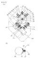
As illustrated inFIGs. 1 ,2(A) , and4 to 7 , each of spherical-body-drivenmodules 10 used in a self-propelledcarriage 10a according to a first embodiment of the present invention is to be attached to a bottom of acarriage frame 11 through at least twosuspension mechanisms 12. - As illustrated in
FIGs. 1 and2(A) , each of the spherical-body-drivenmodules 10 has aspherical body 14 in direct contact with afloor surface 13 from above, afirst drive wheel 15 and asecond drive wheel 16 in contact with a vertically middle position (an equator) of thespherical body 14 from two different, for example, orthogonal, directions (directions of an X-axis and a Y-axis) within a level surface, a first uncontrolled-ball bearing mechanism 17 and a second uncontrolled-ball bearing mechanism 18 positioned on a side opposite to thefirst drive wheel 15 and thesecond drive wheel 16 and respectively receiving reaction force from thefirst drive wheel 15 and thesecond drive wheel 16, a third uncontrolled-ball bearing mechanism 19 at a position above thespherical body 14 and holding thespherical body 14 by receiving a load applied on thespherical body 14, abase 20 at a position above thespherical body 14 and supporting the first and thesecond drive wheels mechanisms 17 to 19 in a suspended state, and acleaning mechanism 21 in contact with thespherical body 14 from a lateral direction and removing refuse adhered to thespherical body 14. Also, acover 22 preventing dropping of thespherical body 14 is provided to thebase 20 through supportingmembers 23. Detailed descriptions will hereunder be given. - The
spherical body 14 has a multilayer structure (specifically, a double structure) having, for example, a spherical core material, and an outer shell covering the core material and in direct contact with thefloor surface 13. Here, the core material becomes formed by, for example, hard plastic such as MC nylon or metal, and the outer shell becomes formed by, for example, rubber such as urethane, or polyacetal resin (an example of non-rigid plastic). A diameter of thespherical body 14 is, for example, in the range from 100 to 150 mm, and a thickness of the outer shell formed of rubber or non-rigid plastic is from 5 to 15 mm. Due to such the structure, deformation of thespherical body 14 can be controlled even when a load is applied on thespherical body 14, and at the same time, slippage hardly occurs between thespherical body 14 and thefloor surface 13, and when turning force is given to thespherical body 14, thespherical body 14 becomes capable of moving on thefloor surface 13. Here, spherical bodies can alternatively be composed of uniform plastic (hard plastic is desirable), non-rigid plastic such as urethane, or rubber, or metal. - As illustrated in
FIG. 2(B) , thecleaning mechanism 21 has arefuse removing member 24 in direct contact with part of a surface of thespherical body 14, a holdingmember 25 holding therefuse removing member 24 in a curved state having a same curvature as that of thespherical body 14, a first attachingmember 26 to be connected to the holdingmember 25 through a spring (not illustrated) that is an example of elastic materials, and a second attachingmember 27 holding the first attachingmember 26 at a lower position of thebase 20. Due to such the structure, when the spring is kept in a compressed state, the holdingmember 25 can be biased on the side of thespherical body 14 with respect to the second attachingmember 27, which enables pressing the surface of thespherical body 14 by means of therefuse removing member 24, moving refuse adhered to the surface of thespherical body 14 to the side of therefuse removing member 24 and removing the refuse from the surface of thespherical body 14. Therefuse removing member 24 can be formed by a cloth, non-woven cloth and the like. - The
first drive wheel 15 and thesecond drive wheel 16 are in direct contact with thespherical body 14 respectively from an X-axis direction and a Y-axis direction that become orthogonal to each other toward a center of thespherical body 14 in planar view. Thefirst drive wheel 15 and thesecond drive wheel 16 are connected respectively with a firstrotary drive source 28 and a secondrotary drive source 29, including adecelerating mechanism 30. Here, an outer periphery side of each of the first and thesecond drive wheels spherical body 14 is arc-like in projecting cross-section, and formed of hard rubber (e.g., urethane) or resin (e.g., polyacetal). Also, the first and the secondrotary drive sources second drive wheels - In
FIGs. 1 and2(A) , the first and the secondrotary drive sources decelerating mechanism 30 are positioned above thebase 20, and the first and thesecond drive wheels base 20. Apulley 31 attached to an output shaft of thedecelerating mechanism 30 andpulleys 31 a each attached to an axle of one of the first and thesecond drive wheels belt 31 b, and the first and thesecond drive wheels rotary drive sources base 20. - The third uncontrolled-
ball bearing mechanism 19 has a first uncontrolled-ball supporting body 32 and a second uncontrolled-ball supporting body 33 positioned above the equator of thespherical body 14 and respectively receiving reaction force from thefirst drive wheel 15 and thesecond drive wheel 16, and a third uncontrolled-ball supporting body 34 eccentrically provided above thespherical body 14, and pressing thespherical body 14 to the first and thesecond drive wheels spherical body 14. In this embodiment, Ball Bear (a brand name) is used as the uncontrolled-ball supporting bodies. - For example, as illustrated in
FIG. 3 , in planar view, when thesecond drive wheel 16 is arranged at a position of 0°, and thefirst drive wheel 15 is arranged at a position that is 90° anti-clockwise from thesecond drive wheel 16, the second uncontrolled-ball supporting body 33 becomes arranged at an angular position that is 180° anti-clockwise from thesecond drive wheel 16, and provided that a radius of thespherical body 14 is R, the second uncontrolled-ball supporting body 33 becomes arranged at a position ranging from 0.2 R to 0.5 R from the center of thespherical body 14. Also, the first uncontrolled-ball supporting body 32 becomes arranged at an angular position that is 270° anti-clockwise from thesecond drive wheel 16, and within a range from 0.2 R to 0.5 R from the center of thespherical body 14. The third uncontrolled-ball supporting body 34 becomes arranged at an angular position that is from 200° to 270° anti-clockwise from thesecond drive wheel 16, and within a range from 0.05 R to 0.2 R from the center of thespherical body 14.
The third uncontrolled-ball supporting body 34 is attached to an undersurface of the base 20 through a third attachingbase 35 so as to be in direct contact with thespherical body 14 from above and toward a vertical direction, and the first and the second uncontrolled-ball supporting bodies bases spherical body 14 toward the center of thespherical body 14. - As illustrated in
FIGs. 1 to 3 , the first uncontrolled-ball bearing mechanism 17 has a fourth uncontrolled-ball supporting body 38 provided at a part on the equator of thespherical body 14 on a side opposite to the contact site of thefirst drive wheel 15 and the equator so as to be in direct contact with thespherical body 14 toward the center of thespherical body 14, and aposition adjusting mechanism 39 attached to the undersurface of thebase 20, holding the fourth uncontrolled-ball supporting body 38, and moving up and down with respect to the center of thespherical body 14. Also, the second uncontrolled-ball bearing mechanism 18 has a fifth uncontrolled-ball supporting body 40 provided at a part on the equator of thespherical body 14 on a side opposite to the contact site of thesecond drive wheel 16 and the equator so as to be in direct contact with thespherical body 14 toward the center of thespherical body 14, and aposition adjusting mechanism 41 attached to the undersurface of thebase 20, holding the fifth uncontrolled-ball supporting body 40, and moving up and down with respect to the center of thespherical body 14. - By the provision of the first and the second uncontrolled-
ball bearing mechanisms spherical body 14, the contact between thespherical body 14 and thefirst drive wheel 15 and between thespherical body 14 and thesecond drive wheel 16 can be maintained. Also, by the provision of the third uncontrolled-ball bearing mechanism 19 (the first to the third uncontrolled-ball supporting bodies 32 to 34), when the third uncontrolled-ball bearing mechanism 19 receives a load applied on thespherical body 14, thespherical body 14 can be pressed to the first and thesecond drive wheels spherical body 14 and thefloor surface 13 becomes high due to a load applied on thespherical body 14, friction force between thespherical body 14 and thefirst drive wheel 15 and friction force between thespherical body 14 and thesecond drive wheel 16 can be made high as well. As a result, slippage of the first and thesecond drive wheels spherical body 14 can be prevented, and rotary drive force can be infallibly transmitted from the first and thesecond drive wheels spherical body 14. - As illustrated in
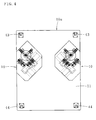
FIGs. 1 , and4 to 7 , in the case of the self-propelledcarriage 10a in which the spherical-body-drivenmodules 10 are provided to thecarriage frame 11 through thesuspension mechanisms 12, one ofuncontrolled wheels 43 each in direct contact with thefloor surface 13 through one of supporting members 43a is attached to each of lower portions of both sides in a width direction on one side of a longitudinal direction (inFIG. 4 , vertical direction on paper) of thecarriage frame 11, and one ofuncontrolled wheels 44 each in direct contact with thefloor surface 13 through one of supportingmembers 44a is attached to each of lower portions of both sides on the other side of the longitudinal direction of thecarriage frame 11. - Each of the spherical-body-driven
modules 10 is attached between one of theuncontrolled wheels 43 and one of theuncontrolled wheels 44 each attached to thecarriage frame 11. It is also possible to attach either theuncontrolled wheels 43 or theuncontrolled wheels 44 to thecarriage frame 11 through a lifting mechanism (e.g., a fluid pressure cylinder). Vertical position of either theuncontrolled wheels 43 or theuncontrolled wheels 44 can thereby be adjusted, enabling thespherical bodies 14 of the spherical-body-drivenmodules 10 to infallibly be in direct contact with thefloor surface 13 together with theuncontrolled wheels carriage frame 11 was, as illustrated inFIG. 4 , rectangular (square, oblong), however, a carriage frame can be in a different shape as well. - As illustrated in
FIG. 1 , each of thesuspension mechanisms 12 is provided standing, through one of first fastening means (e.g., bolts) 48, on a module frame (middle frame) 47 arranged on an upper side of the base 20 through a plurality of supporting members 47a, and an upper part of each of thesuspension mechanisms 12 has one ofcore materials 48a each penetrating through thecarriage frame 11 in a manner that enables thecarriage frame 11 to move up and down, one of coil springs (an example of elastic members) 49 each attached to an outer side of one of thecore materials 48a, one of guidingmembers 45 each having a flange and guiding one of thecore materials 48a each projecting from thecarriage frame 11, and one of second fastening means (e.g., bolts) 46 each fixing one of the guidingmembers 45 to the top of one of thecore materials 48a. - The coil springs 49 become arranged in a compressed state, and when a heavy load is applied on the
carriage frame 11, thecore materials 48a and the guidingmembers 45 remain at each original position, however, the coil springs 49 compress, keeping thespherical bodies 14 from receiving a large load. When changing a load that thespherical bodies 14 receive, the coil springs 49 or the guidingmembers 45 are to be changed, and which to be changed is selected based on a material of thespherical bodies 14, and load capacity of theuncontrolled wheels spherical bodies 14 receive, for example, a load ranging from 0.35 to 0.8 of a load which thecarriage frame 11 receives.
Due to such the structure, even when thefloor surface 13 is uneven, thespherical bodies 14 of the spherical-body-drivenmodules 10 can be made to be in direct contact with thefloor surface 13 in accordance with the condition of unevenness. - A general structure of the self-propelled
carriage 10a is shown inFIGs. 4 to 7 . As described earlier, two spherical-body-drivenmodules 10 are provided on the bottom of thecarriage frame 11, and theuncontrolled wheels carriage frame 11 through the supportingmembers 43a and 44a.
Thiscarriage frame 11 is for moving a bed (an example of conveyance carriages) 50 that is being used in a hospital and the like, and a lifting means 53 is provided to part of thecarriage frame 11 through an attachingmember 52 also working as a guide frame. Aforce sensor 51 is provided to a side (or an inside) of this lifting means 53. - On the top of the lifting means 53, a
placement member 57 in which avalley portion 56 on which a horizontal member (a frame) 55 on an end in a longitudinal direction of thebed 50 becomes placed in a lying state is formed is provided. Theplacement member 57 can be replaced by one in a different shape depending on the type of a conveyance carriage. On the base side of thecarriage frame 11, a grip (a handle) 58 is provided. Thisgrip 58 has aframe body 59 consisting of a pipe material and in a rectangular shape and a supportingpole 60 provided on the bottom of theframe body 59, and aforce sensor 61 is provided to the supportingpole 60. - The
force sensors force sensor 51 to the lifting means 53 and providing theforce sensor 61 to thegrip 58 or to a particular position on thecarriage frame 11 where deformation occurs due to other loads, when an assisting operation for the movement of the self-propelledcarriage 10a is performed with respect to the self-propelledcarriage 10a, a direction of assisted movement (a direction of a load) can be detected by theforce sensors control device 105 driving the spherical-body-drivenmodules 10 based on output of theforce sensors FIG. 11 into thecarriage frame 11, the self-propelledcarriage 10a can be moved to a direction of assisted movement. - It is also possible to provide an auxiliary carriage to a lower portion on one side of a bed, connect this auxiliary carriage to a self-propelled carriage having spherical-body-driven modules from a longitudinal direction, and integrate the bed and the self-propelled carriage. In this case, it is also possible to provide a force sensor detecting movement of the bed to a connected portion of the bed and the self-propelled carriage or to a carriage frame, detect a moving direction of the bed by this force sensor, and move the self-propelled carriage to a direction into which the bed is pushed. Here, it is preferred that a single or a plurality of force sensor(s) detecting the moving direction of the bed be provided to a grip provided to the self-propelled carriage, and/or to the auxiliary carriage.
Additionally, it is preferred that a confirmation sensor or a confirmation switch confirming the connection of the auxiliary carriage with the self-propelled carriage be provided. - As illustrated in
FIGs. 8 and9 , each of spherical-body-drivenmodules 65 for use in a self-propelled carriage according to a second embodiment of the present invention has aspherical body 66 in direct contact with thefloor surface 13 from above and rotating, afirst drive wheel 67 and asecond drive wheel 68 in contact with a vertically middle position of thespherical body 66 from two directions (directions of an X-axis and a Y-axis) orthogonal within a level surface, a first uncontrolled-ball bearing mechanism 69 on a side opposite to thefirst drive wheel 67 and receiving reaction force of thefirst drive wheel 67 and a second uncontrolled-ball bearing mechanism 70 on a side opposite to thesecond drive wheel 68 and receiving reaction force of thesecond drive wheel 68, and a third uncontrolled-ball bearing mechanism 80 at a position above thespherical body 66 and receiving a load applied on thespherical body 66. Here, thespherical body 66 can have a same structure as those of thespherical bodies 14. - The
first drive wheel 67 and thesecond drive wheel 68 are in direct contact with thespherical body 66 respectively from the X-axis direction and the Y-axis direction becoming orthogonal to each other toward a center of thespherical body 66 in planar view. Thefirst drive wheel 67 and thesecond drive wheel 68 are respectively connected to a firstrotary drive source 71 including afirst decelerating mechanism 73 and a secondrotary drive source 72 including asecond decelerating mechanism 74. Here, an outer periphery side of each of the first and thesecond drive wheels spherical body 14 is arc-like in projecting cross-section and formed of hard rubber (e.g., urethane) or resin (e.g., polyacetal). Also, the first and the secondrotary drive sources - The first uncontrolled-
ball bearing mechanism 69 and the second uncontrolled-ball bearing mechanism 70 of each of the spherical-body-drivenmodules 65 respectively have a third uncontrolled-ball supporting body 76 and a fourth uncontrolled-ball supporting body 77, and respectively have aposition adjusting mechanism 78 and aposition adjusting mechanism 79. The third uncontrolled-ball supporting body 76 and the fourth uncontrolled-ball supporting body 77 are respectively provided above an equator of thespherical body 66 and below the equator of thespherical body 66, each being oriented toward the center of thespherical body 66. The third and the fourth uncontrolled-ball supporting bodies ball bearing mechanism 69 receive pressing force of thefirst drive wheel 67, and the third and the fourth uncontrolled-ball supporting bodies ball bearing mechanism 70 receive pressing force of thesecond drive wheel 68. The first uncontrolled-ball bearing mechanism 69 and the second uncontrolled-ball bearing mechanism 70 respectively have theposition adjusting mechanism 78 and theposition adjusting mechanism 79, theposition adjusting mechanism 78 and theposition adjusting mechanism 79 holding the third uncontrolled-ball supporting body 76 and the fourth uncontrolled-ball supporting body 77 each moving up and down with respect to the center of thespherical body 66. Also, the third uncontrolled-ball bearing mechanism 80 has a first uncontrolled-ball supporting body 81 arranged on the top of thespherical body 66, at least three second uncontrolled-ball supporting bodies 82 arranged at upper positions of thespherical body 66 and around the first uncontrolled-ball supporting body 81 (inFIG. 8 , in planar view, each of the second uncontrolled-ball supporting bodies 82 is arranged at one of positions dividing a circumferential direction of a circle centering on the first uncontrolled-ball supporting body 81 into three equal parts), an attachingbase 83 holding the first uncontrolled-ball supporting body 81, and attachingbases 84 holding the second uncontrolled-ball supporting bodies 82, each of the attachingbases ball supporting bodies spherical body 66. - Due to the
position adjusting mechanisms ball bearing mechanisms ball supporting body 76 and the fourth uncontrolled-ball supporting body 77 can infallibly be made to be in direct contact with an upper part of the equator of thespherical body 66 and a lower part of the equator of thespherical body 66, respectively, a directly contacted state between thespherical body 66 and thefirst drive wheel 67 and between thespherical body 66 and thesecond drive wheel 68 can be maintained, and at the same time, reaction force of the first and thesecond drive wheels spherical body 66 can thereby be performed stably. Also, since the third uncontrolled-ball bearing mechanism 80 has the first uncontrolled-ball supporting body 81 arranged on the top of thespherical body 66 and the three second uncontrolled-ball supporting bodies 82 arranged at the upper positions of thespherical body 66 and around the first uncontrolled-ball supporting body 81, a load applied on thespherical body 66 can be received in a well-balanced state, and at the same time, thespherical body 66 can be held stably at a predetermined position. - Additionally, each of the spherical-body-driven
modules 65 has a base 85 to which the first and thesecond drive wheels ball bearing mechanisms cover 88 attached to the base 85 through a plurality of supportingmembers 86, covering the first and thesecond drive wheels ball bearing mechanisms spherical body 66 from anopening 87 formed in an undersurface of thecover 88.
Since the spherical-body-drivenmodules 65 can be used in the same way as the spherical-body-drivenmodules 10, descriptions on a self-propelled carriage for which the spherical-body-drivenmodules 65 are used will be omitted. - In
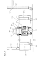
FIG. 10 , an assistive device for walking 89 that is an example of a self-propelled carriage according to a third embodiment of the present invention is illustrated. Each of the spherical-body-driven modules 65 (can be the spherical-body-drivenmodules 10 instead) is provided to acarriage frame 91 through a plurality (three or four is preferable) ofsuspension mechanisms 90, and asupport pole 92 is provided standing on thecarriage frame 91. Aplastic cover body 93 having a large-diameter cylindrical lower part, a nearly conical middle part, and a small-diameter cylindrical upper part is attached to thesupport pole 92 through a plurality of supportingmembers 94. On the upper part of thecover body 93, agrip 95 is provided in a manner that enables thegrip 95 to adjust height, and a user can hold thisgrip 95. Asign 95a represents a screw (a height adjusting means) fixing a position of thegrip 95. Here, atower 92a is formed having thesupport pole 92 and thecover body 93. - A
force sensor 96 is provided to the lower portion of thesupport pole 92. Theforce sensor 96 detects a direction in which a user pushes (a direction of a load), and the spherical-body-drivenmodules 65 move in the pushed direction. A force sensor can be provided to a grip instead. Thisforce sensor 96 is also provided with a sensor detecting a load in a Z-axis direction (longitudinal direction), and when pressing force that is equal to or more than a certain amount is applied in the Z-axis direction, theforce sensor 96 detects this, the spherical-body-drivenmodules 65, that is, behaviors of thespherical bodies 66, stop, and the rotary drive sources brake. - Each of the
suspension mechanisms 90 has one ofcore materials 97 each provided standing on thebase 85, one of coil springs (an example of elastic members) 98 each attached to one of thecore materials 97, and one ofdouble nuts 100 each working as a stopper for one of thecore materials 97 each projecting from thecarriage frame 91.Uncontrolled wheels 102 are provided around thecarriage frame 91 through supportingmembers 101.
It is preferred that a load the spherical-body-drivenmodules 65 bear be from 30 to 80% with respect to a total load on the assistive device for walking 89. - In
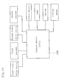
FIG. 11 , acontrol device 105 of the self-propelled carriages according to the first to the third embodiments of the present invention is illustrated. For thecontrol device 105, a programmable controller (or a microcomputer) is used, and a first encoder provided to a rotation axis of a first rotary drive source, a second encoder provided to a rotation axis of a second rotary drive source, a force sensor (one that is store-bought), and a switch are connected to an input side, and the first and the second rotary drive sources, a lifting means, a lamp and the like are connected to an output side. Since the descriptions on the behaviors have been given earlier, they will be omitted. - The descriptions have been given hereinbefore on the present invention with reference to the embodiments. However, the present invention is not limited to the structures described in the above embodiments, and includes other embodiments and variations conceivable within the scope of matters described in the scope of claims. Additionally, the present invention also includes those made by combining composing elements of the first to the third embodiments.
For example, it is also possible to provide spherical-body-driven modules on a bottom of a carriage frame through suspension mechanisms and a force sensor. - In the case of the self-propelled carriages according to the present invention for which the spherical-body-driven modules are used, since the spherical bodies are used, a traveling direction can be changed on the spot, and especially since the suspension mechanisms are provided in between each of the spherical-body-driven modules and the carriage frame, loads of the spherical-body-driven modules and the uncontrolled wheels provided around the carriage frame can be borne, being excellent in traveling stability. Therefore, the self-propelled carriage can be used for beds requiring frequent changes in direction, devices for moving beds, and assistive devices for walking.
- 10: spherical-body-driven module, 10a: self-propelled carriage, 11: carriage frame, 12: suspension mechanism, 13: floor surface, 14: spherical body, 15: first drive wheel, 16: second drive wheel, 17: first uncontrolled-ball bearing mechanism, 18: second uncontrolled-ball bearing mechanism, 19: third uncontrolled-ball bearing mechanism, 20: base, 21: cleaning mechanism, 22: cover, 23: supporting member, 24: refuse removing member, 25: holding member, 26: first attaching member, 27: second attaching member, 28: first rotary drive source, 29: second rotary drive source, 30: decelerating mechanism, 31, 31a: pulley, 31b: belt, 32: first uncontrolled-ball supporting body, 33: second uncontrolled-ball supporting body, 34: third uncontrolled-ball supporting body, 35: third attaching base, 36: first attaching base, 37: second attaching base, 38: fourth uncontrolled-ball supporting body, 39: position adjusting mechanism, 40: fifth uncontrolled-ball supporting body, 41: position adjusting mechanism, 43, 44: uncontrolled wheel, 43a, 44a: supporting member, 45: guiding member: 46: second fastening means, 47: module frame, 47a: supporting member, 48: first fastening means, 48a: core material, 49: coil spring, 50: bed, 51: force sensor, 52: attaching member, 53: lifting means, 55: horizontal member, 56: valley portion, 57: placement member, 58: grip, 59: frame body, 60: supporting pole, 61: force sensor, 65: spherical-body-driven module, 66: spherical body, 67: first drive wheel, 68: second drive wheel, 69: first uncontrolled-ball bearing mechanism, 70: second uncontrolled-ball bearing mechanism, 71: first rotary drive source, 72: second rotary drive source, 73: first decelerating mechanism, 74: second decelerating mechanism, 76: third uncontrolled-ball supporting body, 77: fourth uncontrolled-ball supporting body, 78, 79: position adjusting mechanism, 80: third uncontrolled-ball bearing mechanism, 81: first uncontrolled-ball supporting body, 82: second uncontrolled-ball supporting body, 83, 84: attaching base, 85: base, 86: supporting member, 87: opening, 88: cover, 89: assistive device for walking, 90: suspension mechanism, 91: carriage frame, 92: support pole, 92a: tower, 93: cover body, 94: supporting member, 95: grip, 95a: screw, 96: force sensor, 97: core material, 98: coil spring, 100: double nut, 101: supporting member, 102: uncontrolled wheel, 105: control device
Claims (9)
- A self-propelled carriage having spherical-body-driven modules attached to a base of a carriage frame, each of the spherical-body-driven modules, comprising:a spherical body in direct contact with a floor surface from above;a first drive wheel and a second drive wheel contacting a vertically middle position of the spherical body respectively from an X-axis direction and a Y-axis direction within a level surface, and rotationally driven respectively by a first rotary drive source and a second rotary drive source;a first uncontrolled-ball bearing mechanism and a second uncontrolled-ball bearing mechanism respectively on a side opposite to the first drive wheel and on a side opposite to the second drive wheel and respectively receiving reaction force from the first drive wheel and reaction force from the second drive wheel;a third uncontrolled-ball bearing mechanism at a position above the spherical body and holding the spherical body by receiving a load applied on the spherical body; anda base at a position above the spherical body and supporting the first and the second drive wheels and the first to the third uncontrolled-ball bearing mechanisms, whereineach of the spherical-body-driven modules is provided to the carriage frame through a plurality of suspension mechanisms for each of which an elastic material is used, and uncontrolled wheels in direct contact with the floor surface are provided on a circumference of the carriage frame.
- The self-propelled carriage according to claim 1, wherein
a force sensor detecting force component in an X-axis direction and a Y-axis direction orthogonal to each other within a level surface and a quantity of moment around a Z-axis orthogonal to the level surface is provided to part of the carriage frame, and the spherical-body-driven modules move to a direction of a load applied on the carriage frame. - The self-propelled carriage according to claim 1, wherein
a tower is formed projecting on the carriage frame, the tower is provided with a grip, a force sensor detecting force component in an X-axis direction and a Y-axis direction orthogonal to each other within a planar surface, force component in a Z-axis direction orthogonal to these X-axis and Y-axis directions, and a quantity of moment around the Z-axis is provided to the tower or the grip, and the spherical-body-driven modules move along a direction of a load detected by the force sensor. - The self-propelled carriage according to claim 3, wherein
the force sensor is further provided with a sensor detecting a load in the Z-axis direction, and by detecting a load that is equal to or more than a predetermined load in the Z-axis direction, the spherical body stops. - The self-propelled carriage according to any one of claims 1 to 4, wherein
the spherical body 1) has a multilayer structure having a spherical core material consisting of hard plastic or metal, and an outer shell formed around the core material and consisting of rubber or non-rigid plastic, or 2) consists of hard plastic, non-rigid plastic, rubber, or metal, each of which having a uniform structure. - The self-propelled carriage according to any one of claims 1 to 5, wherein
the third uncontrolled-ball bearing mechanism is at a position above an equator of the spherical body, and has a first uncontrolled-ball supporting body and a second uncontrolled-ball supporting body simultaneously and respectively receiving reaction force from the first drive wheel and reaction force from the second drive wheel, and a third uncontrolled-ball supporting body eccentrically provided above the spherical body and pressing the spherical body to the first and the second drive wheels by receiving a load applied on the spherical body. - The self-propelled carriage according to any one of claims 1 to 5, wherein
the third uncontrolled-ball bearing mechanism has a first uncontrolled-ball supporting body positioned on a top of the spherical body and second uncontrolled-ball supporting bodies arranged in plurality and surrounding the first uncontrolled-ball supporting body, and the first uncontrolled-ball bearing mechanism and the second uncontrolled-ball bearing mechanism respectively have a third uncontrolled-ball supporting body and a fourth uncontrolled-ball supporting body, the third uncontrolled supporting body arranged above the fourth uncontrolled supporting body with the equator of the spherical body in between and respectively receiving pressing force of the first drive wheel and pressing force of the second drive wheel. - The self-propelled carriage according to any one of claims 1 to 7, wherein
a cleaning mechanism in contact with the spherical body from a lateral direction and removing refuse adhered to the spherical body is provided. - The self-propelled carriage according to any one of claims 1 to 8, wherein
a cover preventing dropping of the spherical body is provided to the base through supporting members.
Applications Claiming Priority (2)
| Application Number | Priority Date | Filing Date | Title |
|---|---|---|---|
| JP2013256435 | 2013-12-11 | ||
| PCT/JP2014/082711 WO2015087922A1 (en) | 2013-12-11 | 2014-12-10 | Self-propelled carriage using spherical drive module |
Publications (3)
| Publication Number | Publication Date |
|---|---|
| EP3081452A1 true EP3081452A1 (en) | 2016-10-19 |
| EP3081452A4 EP3081452A4 (en) | 2017-08-23 |
| EP3081452B1 EP3081452B1 (en) | 2021-01-27 |
Family
ID=53371223
Family Applications (1)
| Application Number | Title | Priority Date | Filing Date |
|---|---|---|---|
| EP14869883.0A Not-in-force EP3081452B1 (en) | 2013-12-11 | 2014-12-10 | Self-propelled carriage using spherical drive module |
Country Status (4)
| Country | Link |
|---|---|
| EP (1) | EP3081452B1 (en) |
| JP (1) | JP5908189B2 (en) |
| SG (1) | SG11201510652VA (en) |
| WO (1) | WO2015087922A1 (en) |
Families Citing this family (4)
| Publication number | Priority date | Publication date | Assignee | Title |
|---|---|---|---|---|
| CZ2015620A3 (en) * | 2015-09-13 | 2017-04-26 | České vysoké učení technické v Praze, Fakulta strojní, Ústav výrobních strojů a zařízení | Actuation of a mobile device |
| JP6920726B2 (en) * | 2017-09-07 | 2021-08-18 | 独立行政法人国立高等専門学校機構 | Wheelchair attachment |
| CN111973280B (en) * | 2017-12-27 | 2022-02-22 | 上海微创医疗机器人(集团)股份有限公司 | Surgical robot terminal |
| JP7713222B2 (en) * | 2021-07-02 | 2025-07-25 | 国立大学法人九州工業大学 | Ball-driven transport device and casters equipped therewith |
Family Cites Families (13)
| Publication number | Priority date | Publication date | Assignee | Title |
|---|---|---|---|---|
| JPH0635865Y2 (en) * | 1987-12-22 | 1994-09-21 | 神鋼電機株式会社 | Omnidirectional moving vehicle |
| JPH07257422A (en) * | 1994-03-19 | 1995-10-09 | Hideaki Maehara | Omnidirectional drive wheel and omnidirectional traveling vehicle providing the same |
| JPH1023613A (en) * | 1996-07-04 | 1998-01-23 | Yamaha Motor Co Ltd | Electric moving body |
| JP3826687B2 (en) * | 1999-07-27 | 2006-09-27 | 松下電工株式会社 | Omni-directional cart |
| JP3656500B2 (en) * | 2000-02-24 | 2005-06-08 | 松下電工株式会社 | Omnidirectional cart |
| JP3498044B2 (en) * | 2000-06-14 | 2004-02-16 | 川崎重工業株式会社 | Control device for omnidirectional mobile device |
| JP2004153968A (en) | 2002-10-31 | 2004-05-27 | Seiko Epson Corp | Driving device, traveling body and transport device using the same |
| JP4523244B2 (en) * | 2003-05-22 | 2010-08-11 | 独立行政法人科学技術振興機構 | Power-assisted mobile trolley |
| JP4667439B2 (en) * | 2007-10-29 | 2011-04-13 | Ihi運搬機械株式会社 | Object moving device |
| JP2010008204A (en) * | 2008-06-26 | 2010-01-14 | Nsk Ltd | Force sensing device and wheel type robot |
| JP2010215043A (en) * | 2009-03-16 | 2010-09-30 | Bridgestone Cycle Co | Electric assisting cart |
| JP5633779B2 (en) | 2010-04-30 | 2014-12-03 | 国立大学法人九州工業大学 | Self-supporting walking support device |
| FR2975895B1 (en) * | 2011-05-30 | 2013-06-28 | Commissariat Energie Atomique | VEHICLE HAS AT LEAST THREE STABLE SUPPORT POINTS ON THE GROUND |
-
2014
- 2014-12-10 EP EP14869883.0A patent/EP3081452B1/en not_active Not-in-force
- 2014-12-10 WO PCT/JP2014/082711 patent/WO2015087922A1/en not_active Ceased
- 2014-12-10 JP JP2015550105A patent/JP5908189B2/en active Active
- 2014-12-10 SG SG11201510652VA patent/SG11201510652VA/en unknown
Also Published As
| Publication number | Publication date |
|---|---|
| SG11201510652VA (en) | 2016-01-28 |
| JP5908189B2 (en) | 2016-04-26 |
| EP3081452B1 (en) | 2021-01-27 |
| EP3081452A4 (en) | 2017-08-23 |
| WO2015087922A1 (en) | 2015-06-18 |
| JPWO2015087922A1 (en) | 2017-03-16 |
Similar Documents
| Publication | Publication Date | Title |
|---|---|---|
| EP3081452B1 (en) | Self-propelled carriage using spherical drive module | |
| CN101657347B (en) | Omnidirectional driving device and omnidirectional mobile vehicle using the omnidirectional driving device | |
| US7789175B2 (en) | Modular dual wheel drive assembly, wheeled devices that include modular dual wheel drive assemblies and methods for moving and/or maneuvering wheeled devices using modular dual wheel drive assemblies | |
| EP2999448B1 (en) | Assisted propulsion system, method and chassis | |
| CN108290283A (en) | Coupling arrangement and coupling method | |
| JP2018538018A (en) | Stable wheel assembly and method of use | |
| CN204355187U (en) | Curved surface adaptive safety precaution climbing robot device | |
| KR101835199B1 (en) | Robot for transferring substrate | |
| CN109911060A (en) | A Universal Chassis for Mobile Robots | |
| CN101891053A (en) | Transporter for escalator or moving sidewalk | |
| KR20170084391A (en) | Robot for transferring substrate | |
| CN102712419B (en) | Load transfer device | |
| CN109178768A (en) | A kind of double rolling bed transportation systems and its working method | |
| CN109308071A (en) | A transport trolley with a lifting and rotating mechanism and its control method | |
| CN110254564B (en) | Wheel suspension assembly for AGV trolley | |
| CN115461301A (en) | Unmanned delivery vehicle with payload lifting equipment | |
| CN107823873A (en) | Electric transporting device and its control method at least one people | |
| KR102450985B1 (en) | Caster apparatus and transferring apparatus including the same | |
| KR101627210B1 (en) | Wheel Block Apparatus For Carrying Weight | |
| JP6318081B2 (en) | Sphere drive module and self-propelled carriage using the same | |
| JP2016023027A (en) | Unmanned carrier | |
| CN106043427A (en) | Multi-caterpillar-band type all-directional mobile platform | |
| KR101509083B1 (en) | Moving Type Lifting Apparatus Including Driving Assistance Wheel at Center of Gravity | |
| KR20160047941A (en) | Conveyor device | |
| CN103481276A (en) | Permanent-magnet gap suction apparatus with adjustable suction force |
Legal Events
| Date | Code | Title | Description |
|---|---|---|---|
| PUAI | Public reference made under article 153(3) epc to a published international application that has entered the european phase |
Free format text: ORIGINAL CODE: 0009012 |
|
| 17P | Request for examination filed |
Effective date: 20160711 |
|
| AK | Designated contracting states |
Kind code of ref document: A1 Designated state(s): AL AT BE BG CH CY CZ DE DK EE ES FI FR GB GR HR HU IE IS IT LI LT LU LV MC MK MT NL NO PL PT RO RS SE SI SK SM TR |
|
| AX | Request for extension of the european patent |
Extension state: BA ME |
|
| DAX | Request for extension of the european patent (deleted) | ||
| A4 | Supplementary search report drawn up and despatched |
Effective date: 20170726 |
|
| RIC1 | Information provided on ipc code assigned before grant |
Ipc: B60B 19/14 20060101ALI20170720BHEP Ipc: B62B 3/00 20060101AFI20170720BHEP Ipc: B60B 33/08 20060101ALI20170720BHEP Ipc: B62D 9/00 20060101ALI20170720BHEP Ipc: B62B 5/00 20060101ALI20170720BHEP |
|
| GRAP | Despatch of communication of intention to grant a patent |
Free format text: ORIGINAL CODE: EPIDOSNIGR1 |
|
| STAA | Information on the status of an ep patent application or granted ep patent |
Free format text: STATUS: GRANT OF PATENT IS INTENDED |
|
| INTG | Intention to grant announced |
Effective date: 20200626 |
|
| GRAJ | Information related to disapproval of communication of intention to grant by the applicant or resumption of examination proceedings by the epo deleted |
Free format text: ORIGINAL CODE: EPIDOSDIGR1 |
|
| STAA | Information on the status of an ep patent application or granted ep patent |
Free format text: STATUS: REQUEST FOR EXAMINATION WAS MADE |
|
| GRAS | Grant fee paid |
Free format text: ORIGINAL CODE: EPIDOSNIGR3 |
|
| STAA | Information on the status of an ep patent application or granted ep patent |
Free format text: STATUS: GRANT OF PATENT IS INTENDED |
|
| GRAP | Despatch of communication of intention to grant a patent |
Free format text: ORIGINAL CODE: EPIDOSNIGR1 |
|
| INTC | Intention to grant announced (deleted) | ||
| INTG | Intention to grant announced |
Effective date: 20201127 |
|
| GRAA | (expected) grant |
Free format text: ORIGINAL CODE: 0009210 |
|
| STAA | Information on the status of an ep patent application or granted ep patent |
Free format text: STATUS: THE PATENT HAS BEEN GRANTED |
|
| REG | Reference to a national code |
Ref country code: DE Ref legal event code: R082 Ref document number: 602014074644 Country of ref document: DE Representative=s name: VOSSIUS & PARTNER PATENTANWAELTE RECHTSANWAELT, DE |
|
| AK | Designated contracting states |
Kind code of ref document: B1 Designated state(s): AL AT BE BG CH CY CZ DE DK EE ES FI FR GB GR HR HU IE IS IT LI LT LU LV MC MK MT NL NO PL PT RO RS SE SI SK SM TR |
|
| REG | Reference to a national code |
Ref country code: GB Ref legal event code: FG4D |
|
| REG | Reference to a national code |
Ref country code: CH Ref legal event code: EP |
|
| REG | Reference to a national code |
Ref country code: AT Ref legal event code: REF Ref document number: 1358097 Country of ref document: AT Kind code of ref document: T Effective date: 20210215 |
|
| REG | Reference to a national code |
Ref country code: IE Ref legal event code: FG4D |
|
| REG | Reference to a national code |
Ref country code: DE Ref legal event code: R096 Ref document number: 602014074644 Country of ref document: DE |
|
| REG | Reference to a national code |
Ref country code: NL Ref legal event code: MP Effective date: 20210127 |
|
| REG | Reference to a national code |
Ref country code: LT Ref legal event code: MG9D |
|
| REG | Reference to a national code |
Ref country code: AT Ref legal event code: MK05 Ref document number: 1358097 Country of ref document: AT Kind code of ref document: T Effective date: 20210127 |
|
| PG25 | Lapsed in a contracting state [announced via postgrant information from national office to epo] |
Ref country code: HR Free format text: LAPSE BECAUSE OF FAILURE TO SUBMIT A TRANSLATION OF THE DESCRIPTION OR TO PAY THE FEE WITHIN THE PRESCRIBED TIME-LIMIT Effective date: 20210127 Ref country code: GR Free format text: LAPSE BECAUSE OF FAILURE TO SUBMIT A TRANSLATION OF THE DESCRIPTION OR TO PAY THE FEE WITHIN THE PRESCRIBED TIME-LIMIT Effective date: 20210428 Ref country code: FI Free format text: LAPSE BECAUSE OF FAILURE TO SUBMIT A TRANSLATION OF THE DESCRIPTION OR TO PAY THE FEE WITHIN THE PRESCRIBED TIME-LIMIT Effective date: 20210127 Ref country code: LT Free format text: LAPSE BECAUSE OF FAILURE TO SUBMIT A TRANSLATION OF THE DESCRIPTION OR TO PAY THE FEE WITHIN THE PRESCRIBED TIME-LIMIT Effective date: 20210127 Ref country code: PT Free format text: LAPSE BECAUSE OF FAILURE TO SUBMIT A TRANSLATION OF THE DESCRIPTION OR TO PAY THE FEE WITHIN THE PRESCRIBED TIME-LIMIT Effective date: 20210527 Ref country code: BG Free format text: LAPSE BECAUSE OF FAILURE TO SUBMIT A TRANSLATION OF THE DESCRIPTION OR TO PAY THE FEE WITHIN THE PRESCRIBED TIME-LIMIT Effective date: 20210427 Ref country code: NL Free format text: LAPSE BECAUSE OF FAILURE TO SUBMIT A TRANSLATION OF THE DESCRIPTION OR TO PAY THE FEE WITHIN THE PRESCRIBED TIME-LIMIT Effective date: 20210127 Ref country code: NO Free format text: LAPSE BECAUSE OF FAILURE TO SUBMIT A TRANSLATION OF THE DESCRIPTION OR TO PAY THE FEE WITHIN THE PRESCRIBED TIME-LIMIT Effective date: 20210427 |
|
| PG25 | Lapsed in a contracting state [announced via postgrant information from national office to epo] |
Ref country code: SE Free format text: LAPSE BECAUSE OF FAILURE TO SUBMIT A TRANSLATION OF THE DESCRIPTION OR TO PAY THE FEE WITHIN THE PRESCRIBED TIME-LIMIT Effective date: 20210127 Ref country code: AT Free format text: LAPSE BECAUSE OF FAILURE TO SUBMIT A TRANSLATION OF THE DESCRIPTION OR TO PAY THE FEE WITHIN THE PRESCRIBED TIME-LIMIT Effective date: 20210127 Ref country code: RS Free format text: LAPSE BECAUSE OF FAILURE TO SUBMIT A TRANSLATION OF THE DESCRIPTION OR TO PAY THE FEE WITHIN THE PRESCRIBED TIME-LIMIT Effective date: 20210127 Ref country code: PL Free format text: LAPSE BECAUSE OF FAILURE TO SUBMIT A TRANSLATION OF THE DESCRIPTION OR TO PAY THE FEE WITHIN THE PRESCRIBED TIME-LIMIT Effective date: 20210127 Ref country code: LV Free format text: LAPSE BECAUSE OF FAILURE TO SUBMIT A TRANSLATION OF THE DESCRIPTION OR TO PAY THE FEE WITHIN THE PRESCRIBED TIME-LIMIT Effective date: 20210127 |
|
| PG25 | Lapsed in a contracting state [announced via postgrant information from national office to epo] |
Ref country code: IS Free format text: LAPSE BECAUSE OF FAILURE TO SUBMIT A TRANSLATION OF THE DESCRIPTION OR TO PAY THE FEE WITHIN THE PRESCRIBED TIME-LIMIT Effective date: 20210527 |
|
| REG | Reference to a national code |
Ref country code: DE Ref legal event code: R097 Ref document number: 602014074644 Country of ref document: DE |
|
| PG25 | Lapsed in a contracting state [announced via postgrant information from national office to epo] |
Ref country code: SM Free format text: LAPSE BECAUSE OF FAILURE TO SUBMIT A TRANSLATION OF THE DESCRIPTION OR TO PAY THE FEE WITHIN THE PRESCRIBED TIME-LIMIT Effective date: 20210127 Ref country code: CZ Free format text: LAPSE BECAUSE OF FAILURE TO SUBMIT A TRANSLATION OF THE DESCRIPTION OR TO PAY THE FEE WITHIN THE PRESCRIBED TIME-LIMIT Effective date: 20210127 Ref country code: EE Free format text: LAPSE BECAUSE OF FAILURE TO SUBMIT A TRANSLATION OF THE DESCRIPTION OR TO PAY THE FEE WITHIN THE PRESCRIBED TIME-LIMIT Effective date: 20210127 |
|
| PG25 | Lapsed in a contracting state [announced via postgrant information from national office to epo] |
Ref country code: SK Free format text: LAPSE BECAUSE OF FAILURE TO SUBMIT A TRANSLATION OF THE DESCRIPTION OR TO PAY THE FEE WITHIN THE PRESCRIBED TIME-LIMIT Effective date: 20210127 Ref country code: RO Free format text: LAPSE BECAUSE OF FAILURE TO SUBMIT A TRANSLATION OF THE DESCRIPTION OR TO PAY THE FEE WITHIN THE PRESCRIBED TIME-LIMIT Effective date: 20210127 Ref country code: DK Free format text: LAPSE BECAUSE OF FAILURE TO SUBMIT A TRANSLATION OF THE DESCRIPTION OR TO PAY THE FEE WITHIN THE PRESCRIBED TIME-LIMIT Effective date: 20210127 Ref country code: ES Free format text: LAPSE BECAUSE OF FAILURE TO SUBMIT A TRANSLATION OF THE DESCRIPTION OR TO PAY THE FEE WITHIN THE PRESCRIBED TIME-LIMIT Effective date: 20210127 |
|
| PLBE | No opposition filed within time limit |
Free format text: ORIGINAL CODE: 0009261 |
|
| STAA | Information on the status of an ep patent application or granted ep patent |
Free format text: STATUS: NO OPPOSITION FILED WITHIN TIME LIMIT |
|
| 26N | No opposition filed |
Effective date: 20211028 |
|
| PG25 | Lapsed in a contracting state [announced via postgrant information from national office to epo] |
Ref country code: AL Free format text: LAPSE BECAUSE OF FAILURE TO SUBMIT A TRANSLATION OF THE DESCRIPTION OR TO PAY THE FEE WITHIN THE PRESCRIBED TIME-LIMIT Effective date: 20210127 |
|
| PG25 | Lapsed in a contracting state [announced via postgrant information from national office to epo] |
Ref country code: SI Free format text: LAPSE BECAUSE OF FAILURE TO SUBMIT A TRANSLATION OF THE DESCRIPTION OR TO PAY THE FEE WITHIN THE PRESCRIBED TIME-LIMIT Effective date: 20210127 |
|
| PG25 | Lapsed in a contracting state [announced via postgrant information from national office to epo] |
Ref country code: IT Free format text: LAPSE BECAUSE OF FAILURE TO SUBMIT A TRANSLATION OF THE DESCRIPTION OR TO PAY THE FEE WITHIN THE PRESCRIBED TIME-LIMIT Effective date: 20210127 |
|
| PG25 | Lapsed in a contracting state [announced via postgrant information from national office to epo] |
Ref country code: IS Free format text: LAPSE BECAUSE OF FAILURE TO SUBMIT A TRANSLATION OF THE DESCRIPTION OR TO PAY THE FEE WITHIN THE PRESCRIBED TIME-LIMIT Effective date: 20210527 |
|
| PG25 | Lapsed in a contracting state [announced via postgrant information from national office to epo] |
Ref country code: MC Free format text: LAPSE BECAUSE OF FAILURE TO SUBMIT A TRANSLATION OF THE DESCRIPTION OR TO PAY THE FEE WITHIN THE PRESCRIBED TIME-LIMIT Effective date: 20210127 |
|
| REG | Reference to a national code |
Ref country code: CH Ref legal event code: PL |
|
| REG | Reference to a national code |
Ref country code: BE Ref legal event code: MM Effective date: 20211231 |
|
| PG25 | Lapsed in a contracting state [announced via postgrant information from national office to epo] |
Ref country code: LU Free format text: LAPSE BECAUSE OF NON-PAYMENT OF DUE FEES Effective date: 20211210 Ref country code: IE Free format text: LAPSE BECAUSE OF NON-PAYMENT OF DUE FEES Effective date: 20211210 |
|
| PG25 | Lapsed in a contracting state [announced via postgrant information from national office to epo] |
Ref country code: BE Free format text: LAPSE BECAUSE OF NON-PAYMENT OF DUE FEES Effective date: 20211231 |
|
| PG25 | Lapsed in a contracting state [announced via postgrant information from national office to epo] |
Ref country code: LI Free format text: LAPSE BECAUSE OF NON-PAYMENT OF DUE FEES Effective date: 20211231 Ref country code: CH Free format text: LAPSE BECAUSE OF NON-PAYMENT OF DUE FEES Effective date: 20211231 |
|
| PGFP | Annual fee paid to national office [announced via postgrant information from national office to epo] |
Ref country code: GB Payment date: 20221221 Year of fee payment: 9 Ref country code: FR Payment date: 20221212 Year of fee payment: 9 |
|
| PG25 | Lapsed in a contracting state [announced via postgrant information from national office to epo] |
Ref country code: HU Free format text: LAPSE BECAUSE OF FAILURE TO SUBMIT A TRANSLATION OF THE DESCRIPTION OR TO PAY THE FEE WITHIN THE PRESCRIBED TIME-LIMIT; INVALID AB INITIO Effective date: 20141210 |
|
| PGFP | Annual fee paid to national office [announced via postgrant information from national office to epo] |
Ref country code: DE Payment date: 20221228 Year of fee payment: 9 |
|
| PG25 | Lapsed in a contracting state [announced via postgrant information from national office to epo] |
Ref country code: CY Free format text: LAPSE BECAUSE OF FAILURE TO SUBMIT A TRANSLATION OF THE DESCRIPTION OR TO PAY THE FEE WITHIN THE PRESCRIBED TIME-LIMIT Effective date: 20210127 |
|
| PG25 | Lapsed in a contracting state [announced via postgrant information from national office to epo] |
Ref country code: MK Free format text: LAPSE BECAUSE OF FAILURE TO SUBMIT A TRANSLATION OF THE DESCRIPTION OR TO PAY THE FEE WITHIN THE PRESCRIBED TIME-LIMIT Effective date: 20210127 |
|
| REG | Reference to a national code |
Ref country code: DE Ref legal event code: R119 Ref document number: 602014074644 Country of ref document: DE |
|
| GBPC | Gb: european patent ceased through non-payment of renewal fee |
Effective date: 20231210 |
|
| PG25 | Lapsed in a contracting state [announced via postgrant information from national office to epo] |
Ref country code: MT Free format text: LAPSE BECAUSE OF FAILURE TO SUBMIT A TRANSLATION OF THE DESCRIPTION OR TO PAY THE FEE WITHIN THE PRESCRIBED TIME-LIMIT Effective date: 20210127 |
|
| PG25 | Lapsed in a contracting state [announced via postgrant information from national office to epo] |
Ref country code: DE Free format text: LAPSE BECAUSE OF NON-PAYMENT OF DUE FEES Effective date: 20240702 |
|
| PG25 | Lapsed in a contracting state [announced via postgrant information from national office to epo] |
Ref country code: GB Free format text: LAPSE BECAUSE OF NON-PAYMENT OF DUE FEES Effective date: 20231210 |
|
| PG25 | Lapsed in a contracting state [announced via postgrant information from national office to epo] |
Ref country code: FR Free format text: LAPSE BECAUSE OF NON-PAYMENT OF DUE FEES Effective date: 20231231 |
|
| PG25 | Lapsed in a contracting state [announced via postgrant information from national office to epo] |
Ref country code: GB Free format text: LAPSE BECAUSE OF NON-PAYMENT OF DUE FEES Effective date: 20231210 Ref country code: FR Free format text: LAPSE BECAUSE OF NON-PAYMENT OF DUE FEES Effective date: 20231231 Ref country code: DE Free format text: LAPSE BECAUSE OF NON-PAYMENT OF DUE FEES Effective date: 20240702 |
|
| PG25 | Lapsed in a contracting state [announced via postgrant information from national office to epo] |
Ref country code: TR Free format text: LAPSE BECAUSE OF FAILURE TO SUBMIT A TRANSLATION OF THE DESCRIPTION OR TO PAY THE FEE WITHIN THE PRESCRIBED TIME-LIMIT Effective date: 20210127 |