EP3081130B1 - Hard surface vacuuming device - Google Patents
Hard surface vacuuming device Download PDFInfo
- Publication number
- EP3081130B1 EP3081130B1 EP16169191.0A EP16169191A EP3081130B1 EP 3081130 B1 EP3081130 B1 EP 3081130B1 EP 16169191 A EP16169191 A EP 16169191A EP 3081130 B1 EP3081130 B1 EP 3081130B1
- Authority
- EP
- European Patent Office
- Prior art keywords
- suction
- hard surface
- unit
- handle
- accordance
- Prior art date
- Legal status (The legal status is an assumption and is not a legal conclusion. Google has not performed a legal analysis and makes no representation as to the accuracy of the status listed.)
- Active
Links
- 239000007788 liquid Substances 0.000 claims description 52
- 239000000203 mixture Substances 0.000 claims description 9
- 238000007599 discharging Methods 0.000 claims description 2
- 238000000926 separation method Methods 0.000 description 58
- 239000000428 dust Substances 0.000 description 8
- 230000000694 effects Effects 0.000 description 2
- 230000002349 favourable effect Effects 0.000 description 2
- 210000003813 thumb Anatomy 0.000 description 2
- 238000009423 ventilation Methods 0.000 description 2
- 230000001680 brushing effect Effects 0.000 description 1
- 238000004140 cleaning Methods 0.000 description 1
- 238000005265 energy consumption Methods 0.000 description 1
- 210000003811 finger Anatomy 0.000 description 1
- 210000005224 forefinger Anatomy 0.000 description 1
- 239000011521 glass Substances 0.000 description 1
- 230000005484 gravity Effects 0.000 description 1
- 238000010438 heat treatment Methods 0.000 description 1
- 230000001771 impaired effect Effects 0.000 description 1
- 239000002991 molded plastic Substances 0.000 description 1
- 239000004033 plastic Substances 0.000 description 1
- 230000000284 resting effect Effects 0.000 description 1
- 210000004761 scalp Anatomy 0.000 description 1
- 230000004936 stimulating effect Effects 0.000 description 1
- XLYOFNOQVPJJNP-UHFFFAOYSA-N water Substances O XLYOFNOQVPJJNP-UHFFFAOYSA-N 0.000 description 1
Images
Classifications
-
- A—HUMAN NECESSITIES
- A47—FURNITURE; DOMESTIC ARTICLES OR APPLIANCES; COFFEE MILLS; SPICE MILLS; SUCTION CLEANERS IN GENERAL
- A47L—DOMESTIC WASHING OR CLEANING; SUCTION CLEANERS IN GENERAL
- A47L1/00—Cleaning windows
- A47L1/02—Power-driven machines or devices
- A47L1/05—Hand apparatus with built-in electric motors
-
- A—HUMAN NECESSITIES
- A47—FURNITURE; DOMESTIC ARTICLES OR APPLIANCES; COFFEE MILLS; SPICE MILLS; SUCTION CLEANERS IN GENERAL
- A47L—DOMESTIC WASHING OR CLEANING; SUCTION CLEANERS IN GENERAL
- A47L5/00—Structural features of suction cleaners
- A47L5/12—Structural features of suction cleaners with power-driven air-pumps or air-compressors, e.g. driven by motor vehicle engine vacuum
- A47L5/22—Structural features of suction cleaners with power-driven air-pumps or air-compressors, e.g. driven by motor vehicle engine vacuum with rotary fans
- A47L5/24—Hand-supported suction cleaners
-
- A—HUMAN NECESSITIES
- A47—FURNITURE; DOMESTIC ARTICLES OR APPLIANCES; COFFEE MILLS; SPICE MILLS; SUCTION CLEANERS IN GENERAL
- A47L—DOMESTIC WASHING OR CLEANING; SUCTION CLEANERS IN GENERAL
- A47L7/00—Suction cleaners adapted for additional purposes; Tables with suction openings for cleaning purposes; Containers for cleaning articles by suction; Suction cleaners adapted to cleaning of brushes; Suction cleaners adapted to taking-up liquids
- A47L7/0004—Suction cleaners adapted to take up liquids, e.g. wet or dry vacuum cleaners
- A47L7/0019—Details of the casing
-
- A—HUMAN NECESSITIES
- A47—FURNITURE; DOMESTIC ARTICLES OR APPLIANCES; COFFEE MILLS; SPICE MILLS; SUCTION CLEANERS IN GENERAL
- A47L—DOMESTIC WASHING OR CLEANING; SUCTION CLEANERS IN GENERAL
- A47L7/00—Suction cleaners adapted for additional purposes; Tables with suction openings for cleaning purposes; Containers for cleaning articles by suction; Suction cleaners adapted to cleaning of brushes; Suction cleaners adapted to taking-up liquids
- A47L7/0004—Suction cleaners adapted to take up liquids, e.g. wet or dry vacuum cleaners
- A47L7/0023—Recovery tanks
- A47L7/0038—Recovery tanks with means for emptying the tanks
-
- A—HUMAN NECESSITIES
- A47—FURNITURE; DOMESTIC ARTICLES OR APPLIANCES; COFFEE MILLS; SPICE MILLS; SUCTION CLEANERS IN GENERAL
- A47L—DOMESTIC WASHING OR CLEANING; SUCTION CLEANERS IN GENERAL
- A47L9/00—Details or accessories of suction cleaners, e.g. mechanical means for controlling the suction or for effecting pulsating action; Storing devices specially adapted to suction cleaners or parts thereof; Carrying-vehicles specially adapted for suction cleaners
- A47L9/02—Nozzles
- A47L9/06—Nozzles with fixed, e.g. adjustably fixed brushes or the like
- A47L9/0606—Nozzles with fixed, e.g. adjustably fixed brushes or the like rigidly anchored brushes, combs, lips or pads
- A47L9/0626—Rigidly anchored lips, e.g. nozzles adapted for picking up liquids
-
- A—HUMAN NECESSITIES
- A47—FURNITURE; DOMESTIC ARTICLES OR APPLIANCES; COFFEE MILLS; SPICE MILLS; SUCTION CLEANERS IN GENERAL
- A47L—DOMESTIC WASHING OR CLEANING; SUCTION CLEANERS IN GENERAL
- A47L9/00—Details or accessories of suction cleaners, e.g. mechanical means for controlling the suction or for effecting pulsating action; Storing devices specially adapted to suction cleaners or parts thereof; Carrying-vehicles specially adapted for suction cleaners
- A47L9/28—Installation of the electric equipment, e.g. adaptation or attachment to the suction cleaner; Controlling suction cleaners by electric means
- A47L9/2868—Arrangements for power supply of vacuum cleaners or the accessories thereof
- A47L9/2884—Details of arrangements of batteries or their installation
-
- A—HUMAN NECESSITIES
- A47—FURNITURE; DOMESTIC ARTICLES OR APPLIANCES; COFFEE MILLS; SPICE MILLS; SUCTION CLEANERS IN GENERAL
- A47L—DOMESTIC WASHING OR CLEANING; SUCTION CLEANERS IN GENERAL
- A47L9/00—Details or accessories of suction cleaners, e.g. mechanical means for controlling the suction or for effecting pulsating action; Storing devices specially adapted to suction cleaners or parts thereof; Carrying-vehicles specially adapted for suction cleaners
- A47L9/32—Handles
- A47L9/322—Handles for hand-supported suction cleaners
Definitions
- the invention relates to a hard surface suction device for suctioning off a liquid-air mixture from a hard surface, in particular from a window pane, with the features of the preamble of patent claim 1.
- Such hard surface suction devices are used for vacuuming hard surfaces, for example for vacuuming tiled walls or floors and also for removing a water film from a glass surface, in particular from a window pane.
- Hard surface suction devices of this type have a suction device with the aid of which the hard surface can be suctioned off.
- the suction device comprises a suction nozzle, which usually has at least one flexible wiper lip and can be guided along the hard surface to be suctioned.
- the suction device also has a separation unit with a separation chamber.
- the suction nozzle is in flow connection with the suction inlet of the separation chamber and the separation chamber is in flow connection with a suction unit of the suction device via an air outlet, so that the separation chamber can be subjected to negative pressure by the suction unit. Under the effect of the negative pressure, a suction flow is formed from the suction nozzle through the separation chamber to the suction unit and a liquid-air mixture can be sucked into the separation chamber. At least one separation element, with the aid of which liquid can be separated from the liquid-air mixture, is arranged within the separation chamber. Starting from the separation chamber, the liquid can reach a dirty liquid tank via a liquid outlet, which is used in addition to the suction device.
- such hard surface suction devices have a handle so that they can be held by hand by an operator during their operation and guided along the hard surface to be suctioned off.
- Hard surface suction devices comprising a suction device with a suction nozzle, a separation unit and a suction unit, and further comprising a dirty liquid tank and a handle, the separation unit having a separation chamber in which at least one separation element is arranged and which comprises a suction inlet, a liquid outlet and an air outlet, wherein the suction inlet with the suction nozzle, the liquid outlet with the dirty liquid tank and the air outlet with the suction unit in flow connection are from the publications WO 2009/086891 A1 , WO 2009/086892 A1 and WO 2009/086893 A1 known. They have proven themselves in practice. With their help, window panes in particular can be cleaned effectively. To do this, the user guides the hard surface suction device along the window pane while holding the device by the handle. Over time, however, this can lead to fatigue for the operator, since guiding the device along the window pane requires a certain amount of force.
- a hard surface suction device in the form of a dry vacuum cleaner for vacuuming surfaces that have elevations and depressions, for example keyboards and control panels of computers, pocket calculators, telephones and the like.
- the dry vacuum cleaner has a housing with a suction inlet on which a plurality of suction tubes are arranged.
- the suction tubes are deformable and surrounded by bristles.
- a suction unit that is positioned in the housing, a suction flow can be generated, with the help of which dust can be sucked through the suction tubes into the housing and fed to a dust collection container via a suction outlet.
- the dust collection container is held removably on the housing and has an exhaust air opening on which a dust filter is arranged.
- the dust collection container is positioned next to a housing section which accommodates a battery and can be gripped by the user together with the dust collection container.
- a similarly designed dry vacuum cleaner for removing dust from narrow gaps and angles, such as those found on electrical appliances, is from the publication KR 19980020751 U known.
- the dry vacuum cleaner disclosed therein has a housing designed in the manner of a pistol with a handle which surrounds a dust collecting container.
- a dry vacuum cleaner which is designed in the manner of a clothes brush and is provided for vacuuming items of clothing, is from the publication U.S. 2,665,445 known.
- the dry vacuum cleaner has a housing with a suction inlet on which a brush head for brushing off an item of clothing is arranged, and with an exhaust air opening, which is arranged on an end side of a handle facing away from the brush head, in which a filter bag is positioned.
- a manual window puller is known with a housing that forms a handle.
- a pull-off lip which can be guided along a window pane is held on an end face of the housing facing away from the handle. Liquid can be removed from the window pane and directed into a liquid reservoir which is arranged in the handle.
- a suction device to be held in the hand which can be used in particular for stimulating the scalp but also for suctioning off smaller household items, is from the publication U.S. 2,753,434 known.
- the suction device has a cylindrical housing around which the user can grip.
- a suction inlet is arranged on an end face of the housing and an exhaust air opening is arranged on a rear side facing away from the end face.
- a suction unit positioned in the housing, a suction flow extending through the housing in the longitudinal direction can be generated from the suction inlet to the exhaust air opening.
- a heating device can be positioned at the exhaust air opening so that the suction device can also be used as a hair dryer.
- a floor nozzle is arranged at a front end of the housing and a handle which can be grasped by the user is positioned at a rear end of the housing.
- the tubular housing houses a filter bag.
- a hard surface suction device with the features of the preamble of claim 1 is from the publication WO 2008/065313 A2 known.
- the object of the present invention is to further develop a hard surface suction device of the type mentioned at the outset in such a way that it is easy to handle, it being possible for an operator to move it along a hard surface with less effort.
- the suction device comprises the suction nozzle, the separation unit and the suction unit of the hard surface suction device.
- the handle is arranged below the suction device in relation to an upright position of the hard surface suction device. It has been shown that this can reduce the effort required to handle the hard surface suction device.
- the operator can use the hard surface suction device Take hold of the handle below the suction device. The operator can thus directly support the suction device with their hand. As a result, tilting moments that occur when the hard surface suction device is pivoted can be kept low.
- the handle surrounds at least a part of the dirty liquid tank.
- the dirty liquid tank can be completely surrounded by the handle. It can, however, also be provided that the dirty liquid tank has a first tank area which is surrounded by the handle and a second tank area which protrudes from the handle. It is advantageous here if the area of the dirty liquid tank protruding from the handle is arranged below the handle in relation to an upright position of the hard surface suction device.
- the dirty liquid tank is preferably also arranged below the suction device in relation to an upright position of the hard surface suction device.
- the dirty liquid tank is increasingly filled with liquid which was separated in the separation chamber from the liquid-air mixture sucked off the hard surface and which reaches the dirty liquid tank via the liquid outlet.
- the level of the dirty liquid tank increases, its weight increases, so that the focus of the hard surface suction device is increasingly shifted.
- the dirty liquid tank is preferably arranged directly at the liquid outlet of the separation chamber.
- the suction device has a contact surface from which the handle protrudes.
- the operator can place his thumb and forefinger and / or part of the back of his hand on the contact surface. As a result, the effort required to handle the hard surface suction device can be further reduced.
- the suction unit has a suction turbine which can be set in rotation by an electric motor about a turbine axis in order to form a suction flow.
- the handle is preferably elongated and has a longitudinal axis. It is advantageous if the longitudinal axis of the handle is oriented at an angle to the turbine axis.
- the longitudinal axis of the handle advantageously intersects the turbine axis in the area of the separation unit or in the area of the suction unit.
- the handle is arranged below the suction unit in relation to an upright position of the hard surface suction device.
- the handle thus directly absorbs the weight of the suction unit.
- the handle is arranged below the separation unit in relation to an upright position of the hard surface suction device.
- the suction unit can be grasped from under by an operator. This enables the operator to directly support the suction unit by hand.
- the hard surface suction device has at least one rechargeable battery. This means that the hard surface suction device can be operated independently of access to a socket. This facilitates the handling of the hard surface suction device.
- the handle forms a receiving space in which at least one rechargeable battery can be inserted.
- the at least one rechargeable battery is expediently kept exchangeable in the handle.
- the at least one rechargeable battery can be charged by means of an external charger.
- the hard surface suction device according to the invention in a preferred embodiment of the invention has charging electronics for charging the rechargeable battery, the charging electronics being connectable to an external power supply device, for example a charger.
- the dirty liquid tank defines a footprint for placing the hard surface suction device on a surface.
- the suction unit has a turbine inlet which is arranged at the air outlet of the separation chamber.
- the flow path between the separation chamber and the suction unit can therefore be designed to be particularly short. This increases the efficiency of the hard surface suction device and has the consequence that the suction unit can be equipped with a smaller electric motor so that the weight and energy consumption of the hard surface suction device can be reduced. The lower weight facilitates the handling of the hard surface suction device.
- a suction pipe is arranged at the turbine inlet, which dips into the separation chamber.
- the free end of the suction pipe can be arranged at a distance from a separation element which is in the Separation chamber is positioned. The risk of liquid being sucked into the suction unit can thus be kept low.
- the at least one separation element can be designed, for example, in the form of a baffle wall.
- the baffle wall is preferably curved convexly in the direction of the suction inlet of the separation chamber.
- the at least one baffle wall is preferably connected in one piece to a housing of the separation unit.
- the housing of the separation unit and the at least one baffle wall together form a one-piece plastic molded part.
- the suction nozzle, the suction unit and the dirty liquid tank are advantageously releasably connectable to the separation unit.
- the suction nozzle, the suction unit and / or the dirty liquid tank can be releasably latched to the separation unit. This allows the user to easily dismantle the hard surface suction device for cleaning.
- the separation unit and the suction unit have a common housing on which the dirty liquid tank and / or the handle are detachably held.
- the separation unit and the suction unit form a common structural unit on which the dirty liquid tank and / or the handle are detachably held.
- the suction nozzle is also detachably held on the common housing of the separation unit and suction unit.
- the handle can be detachably connected to the separation unit and / or to the suction unit. In such a configuration, it is advantageous if the separation unit and the suction unit can also be separated from one another.
- the suction unit together with at least part of the handle, forms a structural unit that can be detachably connected to the separation unit.
- the part of the handle that forms a common structural unit with the suction unit comprises a rechargeable battery and / or a switch for switching the hard surface suction device on and off, because the design in the form of a common structural unit means that a removable electrical connection between the part of the handle receiving the rechargeable battery and / or the electrical switch and the suction unit is not required.
- a suction flow is generated by the suction unit, under the effect of which a liquid-air mixture can be sucked into the separation chamber.
- Liquid separated from the liquid-air mixture can get from the separation chamber via the liquid outlet to the dirty liquid tank and the air can flow into the suction unit via the air outlet and be discharged from the outside in the form of exhaust air.
- the handle advantageously comprises at least one opening for discharging exhaust air on its side facing away from the suction device.
- the operator can grip the handle.
- the exhaust air is passed through the handle and released to the outside on the side facing away from the suction device. This prevents the operator from being impaired by the exhaust air.
- the separation unit in combination with the handle, forms a recess into which the suction unit can be inserted.
- the suction unit be fixed on the one hand to the separation unit and on the other hand to the handle, for example with the aid of a releasable locking connection.
- the handle takes at least one rechargeable battery
- releasable electrical connecting elements are arranged in the area between the handle and the suction unit, via which the at least one rechargeable battery can be electrically connected to an electric motor and / or to a control device of the electric motor is.
- a particularly simple assembly of the hard surface suction device is achieved in a further development of the invention in that the suction unit is held on one side of the separation unit.
- the separation unit and the handle can be designed as a one-piece molded plastic part on which the suction unit is detachably held.
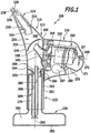
- FIG. 1 an embodiment of a hard surface suction device according to the invention is shown schematically, which is assigned the reference numeral 200 as a whole.
- the hard surface suction device 200 comprises a suction device 212 with a suction nozzle 214, a separation unit 216 and a suction unit 218.
- the hard surface suction device 200 has a dirty liquid tank 220 and a handle 222.
- the suction nozzle 214 comprises a suction channel 224, which at its free end carries a first flexible wiper lip 226 and a second flexible wiper lip 228, which define a suction mouth 230. With a suction mouth 230 The rear end region facing away from it, the suction channel 224 dips into a separation chamber 232, the suction channel 224 reaching through a suction inlet 234 of the separation chamber 232.
- a pipe section 238 is arranged, which extends through an air outlet 240 of the separation chamber 32 and is fixed to a turbine inlet 242 of the suction unit 218.
- the suction unit 218 comprises a suction turbine 244 and an electric motor 246, which sets the suction turbine 244 in rotation about a turbine axis 248. To control the electric motor 246, the suction unit 218 has a control device 250.
- the separation chamber 232 comprises a liquid outlet 252, which is formed by an outlet funnel 254.
- the separation chamber 232 is surrounded by a separation housing 256 with an end wall 258 which has the suction inlet 234, a rear wall 260 which has the air outlet 240, and with an annular wall 270 via which the rear wall 260 is connected to the end wall 258.
- the handle 222 of the hard surface suction device 200 is shown in FIG Figure 1 shown upright position below the separation unit 216.
- the handle 222 forms a sleeve 261 which is connected in one piece to the rear wall 260 and to the annular wall 270 of the separator housing 256.
- the sleeve 261 defines a longitudinal axis 265 of the handle 222, which in the FIG Figure 1 illustrated upright position of the hard surface suction device 200 is aligned essentially vertically.
- the suction unit 218 is detachably held on one side on the rear wall 260 of the separator housing 256.
- latching elements for example are used which are known per se to the person skilled in the art and are therefore in Figure 1 are not shown to achieve a better overview.
- a rechargeable battery 267 is integrated in its suction unit 218 and is connected to the control device 250 via electrical connecting lines.
- the control device 250 is electrically connected via a control line to a switch 269, which is arranged in a recess 273 on an underside 271 of the suction unit 218.
- the rechargeable battery 267 can be connected to an external charger via a connection socket 277 arranged on the rear side 275 of the suction unit 218.
- the sleeve 261 forming the handle 222 is designed to be open at its end facing away from the separation unit 216.
- the sleeve 261 accommodates a first tank area 279 of the dirty liquid tank 222, which is adjoined outside the sleeve 261 by a second tank area 281 with a significantly larger diameter.
- the dirty liquid tank 220 forms a floor space 283 with which the hard surface suction device 200 can be placed on a surface.
- the dirty liquid tank 220 of the hard surface suction device 200 accommodates a filling device 284 with a filling channel 286 and a ventilation channel 288. Liquid that is separated in the separation chamber 232 can enter the dirty liquid tank 220 via the outlet funnel 254 and the filling channel 286. Air can flow into the separation chamber 232 from the dirty liquid tank 220 via the ventilation duct 288.
- the dirty liquid tank 220 can be separated from the separator housing 256 so that the dirty liquid tank 220, the suction nozzle 214 and also the separating chamber 232 can be cleaned by an operator if necessary.
- a suction flow can be generated by means of the suction turbine 244, so that a liquid-air mixture can be sucked into the separation chamber 232 via the suction nozzle 214.
- the sucked in air can be fed from the suction unit via air outlet openings 290 to the sleeve 261.
- the first tank area 279 of the dirty liquid tank 220 and the sleeve 261 define an air outlet channel 292 between them, which extends along the first tank area 279 to the free end of the sleeve 261, so that the exhaust air of the suction unit in the area between the sleeve 261 and the from the Sleeve 261 protruding second tank area 281 can be released to the outside.
- An operator can grip the hard surface suction device 200 on the sleeve-shaped handle 222 below the separation unit 216, the suction unit 218 resting with its underside 271 in the area between the index finger and thumb on the back of the operator's hand. Tilting moments that occur when guiding the hard surface suction device 200 along a hard surface can thereby be kept low. This facilitates the handling of the hard surface suction device 200.
Landscapes
- Engineering & Computer Science (AREA)
- Mechanical Engineering (AREA)
- Cleaning In General (AREA)
- Nozzles For Electric Vacuum Cleaners (AREA)
- External Artificial Organs (AREA)
- Catching Or Destruction (AREA)
Description
Die Erfindung betrifft ein Hartflächenabsauggerät zum Absaugen eines Flüssigkeits-Luftgemisches von einer Hartfläche, insbesondere von einer Fensterscheibe, mit den Merkmalen des Oberbegriffes von Patentanspruch 1.The invention relates to a hard surface suction device for suctioning off a liquid-air mixture from a hard surface, in particular from a window pane, with the features of the preamble of patent claim 1.
Derartige Hartflächenabsauggeräte kommen zum Absaugen von Hartflächen zum Einsatz, beispielsweise zum Absaugen gefliester Wände oder Böden und auch zum Entfernen eines Wasserfilms von einer Glasfläche, insbesondere von einer Fensterscheibe. Hartflächenabsauggeräte dieser Art weisen eine Absaugeinrichtung auf, mit deren Hilfe die Hartfläche abgesaugt werden kann. Die Absaugeinrichtung umfasst eine Saugdüse, die üblicherweise mindestens eine flexible Abstreiflippe aufweist und an der abzusaugenden Hartfläche entlanggeführt werden kann. Die Absaugeinrichtung weist außerdem eine Abscheideeinheit auf mit einer Abscheidekammer. Die Saugdüse steht mit dem Saugeinlass der Abscheidekammer in Strömungsverbindung und über einen Luftauslass steht die Abscheidekammer mit einem Saugaggregat der Absaugeinrichtung in Strömungsverbindung, so dass die Abscheidekammer vom Saugaggregat mit Unterdruck beaufschlagt werden kann. Unter der Wirkung des Unterdrucks bildet sich eine Saugströmung von der Saugdüse durch die Abscheidekammer hindurch zum Saugaggregat und ein Flüssigkeits-Luftgemisch kann in die Abscheidekammer eingesaugt werden. Innerhalb der Abscheidekammer ist mindestens ein Abscheideelement angeordnet, mit dessen Hilfe Flüssigkeit aus dem Flüssigkeits-Luftgemisch abgeschieden werden kann. Ausgehend von der Abscheidekammer kann die Flüssigkeit über einen Flüssigkeitsauslass in einen Schmutzflüssigkeitstank gelangen, der zusätzlich zur Absaugeinrichtung zum Einsatz kommt. Ergänzend weisen derartige Hartflächenabsauggeräte einen Handgriff auf, so dass sie von einer Bedienungsperson während ihres Betriebs mit der Hand gehalten und an der abzusaugenden Hartfläche entlanggeführt werden können.Such hard surface suction devices are used for vacuuming hard surfaces, for example for vacuuming tiled walls or floors and also for removing a water film from a glass surface, in particular from a window pane. Hard surface suction devices of this type have a suction device with the aid of which the hard surface can be suctioned off. The suction device comprises a suction nozzle, which usually has at least one flexible wiper lip and can be guided along the hard surface to be suctioned. The suction device also has a separation unit with a separation chamber. The suction nozzle is in flow connection with the suction inlet of the separation chamber and the separation chamber is in flow connection with a suction unit of the suction device via an air outlet, so that the separation chamber can be subjected to negative pressure by the suction unit. Under the effect of the negative pressure, a suction flow is formed from the suction nozzle through the separation chamber to the suction unit and a liquid-air mixture can be sucked into the separation chamber. At least one separation element, with the aid of which liquid can be separated from the liquid-air mixture, is arranged within the separation chamber. Starting from the separation chamber, the liquid can reach a dirty liquid tank via a liquid outlet, which is used in addition to the suction device. In addition, such hard surface suction devices have a handle so that they can be held by hand by an operator during their operation and guided along the hard surface to be suctioned off.
Hartflächenabsauggeräte umfassend eine Absaugeinrichtung mit einer Saugdüse, einer Abscheideeinheit und einem Saugaggregat, und weiter umfassend einen Schmutzflüssigkeitstank und einen Handgriff, wobei die Abscheideeinheit eine Abscheidekammer aufweist, in der mindestens ein Abscheideelement angeordnet ist und die einen Saugeinlass, einen Flüssigkeitsauslass und einen Luftauslass umfasst, wobei der Saugeinlass mit der Saugdüse, der Flüssigkeitsauslass mit dem Schmutzflüssigkeitstank und der Luftauslass mit dem Saugaggregat in Strömungsverbindung steht, sind aus den Veröffentlichungen
Aus der Veröffentlichung
Ein ähnlich ausgestalteter Trockensauger zum Entfernen von Staub aus engen Spalten und Winkeln, wie sie beispielsweise an Elektrogeräten anzutreffen sind, ist aus der Veröffentlichung
Ein Trockensauger, der nach Art einer Kleiderbürste ausgestaltet ist und zum Absaugen von Kleidungsstücken vorgesehen ist, ist aus der Veröffentlichung
Aus der Veröffentlichung
Ein in der Hand zu haltendes Sauggerät, das insbesondere zur Stimulation der Kopfhaut aber auch zum Absaugen kleinerer Haushaltsgegenstände zum Einsatz kommen kann, ist aus der Veröffentlichung
Aus der Veröffentlichung
Ein weiterer Trockensauger mit einem rohrförmigen Gehäuse offenbart die Veröffentlichung
Ein Hartflächenabsauggerät mit den Merkmalen des Oberbegriffes von Patentanspruch 1 ist aus der Veröffentlichung
Aufgabe der vorliegenden Erfindung ist es, ein Hartflächenabsauggerät der eingangs genannten Art derart weiterzubilden, dass es eine einfache Handhabung aufweist, wobei es von einer Bedienungsperson mit geringerem Kraftaufwand an einer Hartfläche entlanggeführt werden kann.The object of the present invention is to further develop a hard surface suction device of the type mentioned at the outset in such a way that it is easy to handle, it being possible for an operator to move it along a hard surface with less effort.
Diese Aufgabe wird durch ein Hartflächenabsauggerät mit den Merkmalen von Patentanspruch 1 gelöst.This object is achieved by a hard surface suction device with the features of patent claim 1.
Wie bereits erwähnt, umfasst die Absaugeinrichtung die Saugdüse, die Abscheideeinheit und das Saugaggregat des Hartflächenabsauggerätes. Der Handgriff ist bezogen auf eine aufrechte Stellung des Hartflächenabsauggerätes unterhalb der Absaugeinrichtung angeordnet. Es hat sich gezeigt, dass dadurch der Kraftaufwand bei der Handhabung des Hartflächenabsauggerätes reduziert werden kann. Die Bedienungsperson kann das Hartflächenabsauggerät unterhalb der Absaugeinrichtung am Handgriff ergreifen. Mit ihrer Hand kann somit die Bedienungsperson die Absaugeinrichtung unmittelbar abstützen. Dadurch können beim Schwenken des Hartflächenabsauggerätes auftretende Kippmomente gering gehalten werden.As already mentioned, the suction device comprises the suction nozzle, the separation unit and the suction unit of the hard surface suction device. The handle is arranged below the suction device in relation to an upright position of the hard surface suction device. It has been shown that this can reduce the effort required to handle the hard surface suction device. The operator can use the hard surface suction device Take hold of the handle below the suction device. The operator can thus directly support the suction device with their hand. As a result, tilting moments that occur when the hard surface suction device is pivoted can be kept low.
Gemäß der Erfindung umgibt der Handgriff zumindest einen Teil des Schmutzflüssigkeitstanks. Der Schmutzflüssigkeitstank kann vollständig vom Handgriff umgeben sein. Es kann allerdings auch vorgesehen sein, dass der Schmutzflüssigkeitstank einen ersten Tankbereich aufweist, der vom Handgriff umgeben ist, sowie einen zweiten Tankbereich, der aus dem Handgriff herausragt. Hierbei ist es von Vorteil, wenn der aus dem Handgriff herausragende Bereich des Schmutzflüssigkeitstanks bezogen auf eine aufrechte Stellung des Hartflächenabsauggerätes unterhalb des Handgriffs angeordnet ist.According to the invention, the handle surrounds at least a part of the dirty liquid tank. The dirty liquid tank can be completely surrounded by the handle. It can, however, also be provided that the dirty liquid tank has a first tank area which is surrounded by the handle and a second tank area which protrudes from the handle. It is advantageous here if the area of the dirty liquid tank protruding from the handle is arranged below the handle in relation to an upright position of the hard surface suction device.
Bevorzugt ist ergänzend zum Handgriff auch der Schmutzflüssigkeitstank bezogen auf eine aufrechte Stellung des Hartflächenabsauggeräts unterhalb der Absaugeinrichtung angeordnet. Im Laufe des Betriebs füllt sich der Schmutzflüssigkeitstank zunehmend mit Flüssigkeit, die in der Abscheidekammer aus dem von der Hartfläche abgesaugten Flüssigkeits-Luftgemisch abgeschieden wurde und über den Flüssigkeitsauslass in den Schmutzflüssigkeitstank gelangt. Mit zunehmendem Füllstand des Schmutzflüssigkeitstanks erhöht sich dessen Gewicht, so dass sich der Schwerpunkt des Hartflächenabsauggerätes zunehmend verlagert. Durch die Positionierung sowohl des Schmutzflüssigkeitstanks als auch des Handgriffs unterhalb der Absaugeinrichtung kann auch bei zunehmender Schwerpunktsverlagerung das beim Entlangführen des Hartflächenabsauggerätes an der Hartfläche auftretende Kippmoment und damit der von der Bedienungsperson aufzuwendende Kraftaufwand gering gehalten werden.In addition to the handle, the dirty liquid tank is preferably also arranged below the suction device in relation to an upright position of the hard surface suction device. In the course of operation, the dirty liquid tank is increasingly filled with liquid which was separated in the separation chamber from the liquid-air mixture sucked off the hard surface and which reaches the dirty liquid tank via the liquid outlet. As the level of the dirty liquid tank increases, its weight increases, so that the focus of the hard surface suction device is increasingly shifted. By positioning both the dirty liquid tank and the handle below the suction device, the tilting moment that occurs when the hard surface suction device is moved along the hard surface and thus the effort required by the operator can be kept low, even with increasing shift in the center of gravity.
Der Schmutzflüssigkeitstank ist bevorzugt unmittelbar am Flüssigkeitsauslass der Abscheidekammer angeordnet.The dirty liquid tank is preferably arranged directly at the liquid outlet of the separation chamber.
Von Vorteil ist es, wenn die Absaugeinrichtung eine Anlagefläche aufweist, von der der Handgriff absteht. An die Anlagefläche kann die Bedienungsperson beim Ergreifen des Handgriffs Daumen und Zeigefinger und/oder einen Teil ihres Handrückens anlegen. Dadurch kann der zur Handhabung des Hartflächenabsauggerätes erforderliche Kraftaufwand weiter verringert werden.It is advantageous if the suction device has a contact surface from which the handle protrudes. When gripping the handle, the operator can place his thumb and forefinger and / or part of the back of his hand on the contact surface. As a result, the effort required to handle the hard surface suction device can be further reduced.
Das Saugaggregat weist eine Saugturbine auf, die von einem Elektromotor um eine Turbinenachse in Drehung versetzt werden kann, um eine Saugströmung auszubilden. Der Handgriff ist bevorzugt länglich ausgebildet und weist eine Längsachse auf. Von Vorteil ist es, wenn die Längsachse des Handgriffs in einem Winkel zur Turbinenachse ausgerichtet ist.The suction unit has a suction turbine which can be set in rotation by an electric motor about a turbine axis in order to form a suction flow. The handle is preferably elongated and has a longitudinal axis. It is advantageous if the longitudinal axis of the handle is oriented at an angle to the turbine axis.
Günstigerweise schneidet die Längsachse des Handgriffs die Turbinenachse im Bereich der Abscheideeinheit oder im Bereich des Saugaggregates.The longitudinal axis of the handle advantageously intersects the turbine axis in the area of the separation unit or in the area of the suction unit.
Bei einer bevorzugten Ausgestaltung des erfindungsgemäßen Hartflächenabsauggerätes ist der Handgriff bezogen auf eine aufrechte Stellung des Hartflächenabsauggerätes unterhalb des Saugaggregates angeordnet. Der Handgriff nimmt somit unmittelbar das Gewicht des Saugaggregates auf.In a preferred embodiment of the hard surface suction device according to the invention, the handle is arranged below the suction unit in relation to an upright position of the hard surface suction device. The handle thus directly absorbs the weight of the suction unit.
Alternativ kann vorgesehen sein, dass der Handgriff bezogen auf eine aufrechte Stellung des Hartflächenabsauggerätes unterhalb der Abscheideeinheit angeordnet ist.Alternatively, it can be provided that the handle is arranged below the separation unit in relation to an upright position of the hard surface suction device.
Es kann vorgesehen sein, dass das Saugaggregat von einer Bedienungsperson untergreifbar ist. Dies ermöglicht es der Bedienungsperson, das Saugaggregat unmittelbar mit der Hand abzustützen.It can be provided that the suction unit can be grasped from under by an operator. This enables the operator to directly support the suction unit by hand.
Günstig ist es, wenn das Hartflächenabsauggerät zumindest eine wiederaufladbare Batterie aufweist. Dadurch kann das Hartflächenabsauggerät unabhängig vom Zugang zu einer Steckdose betrieben werden. Dies erleichtert die Handhabung des Hartflächenabsauggerätes.It is favorable if the hard surface suction device has at least one rechargeable battery. This means that the hard surface suction device can be operated independently of access to a socket. This facilitates the handling of the hard surface suction device.
Von Vorteil ist es, wenn zumindest eine wiederaufladbare Batterie im Handgriff positioniert ist. Der Handgriff bildet bei einer derartigen Ausgestaltung einen Aufnahmeraum, in den mindestens eine wiederaufladbare Batterie eingesetzt werden kann. Günstigerweise ist die mindestens eine wiederaufladbare Batterie im Handgriff austauschbar gehalten.It is advantageous if at least one rechargeable battery is positioned in the handle. In such a configuration, the handle forms a receiving space in which at least one rechargeable battery can be inserted. The at least one rechargeable battery is expediently kept exchangeable in the handle.
Es kann vorgesehen sein, dass die mindestens eine wiederaufladbare Batterie mittels eines externen Ladegeräts geladen werden kann.It can be provided that the at least one rechargeable battery can be charged by means of an external charger.
Zusätzlich zu einer wiederaufladbaren Batterie weist das erfindungsgemäße Hartflächenabsauggerät bei einer bevorzugten Ausgestaltung der Erfindung eine Ladeelektronik auf zum Aufladen der wiederaufladbaren Batterie, wobei die Ladeelektronik an eine externe Spannungsversorgungseinrichtung anschließbar ist, beispielsweise an ein Ladegerät.In addition to a rechargeable battery, the hard surface suction device according to the invention in a preferred embodiment of the invention has charging electronics for charging the rechargeable battery, the charging electronics being connectable to an external power supply device, for example a charger.
Der Schmutzflüssigkeitstank definiert bei einer vorteilhaften Ausführungsform eine Stellfläche zum Abstellen des Hartflächenabsauggerätes auf einem Untergrund.In an advantageous embodiment, the dirty liquid tank defines a footprint for placing the hard surface suction device on a surface.
Günstig ist es, wenn das Saugaggregat einen Turbineneinlass aufweist, der am Luftauslass der Abscheidekammer angeordnet ist. Der Strömungsweg zwischen der Abscheidekammer und dem Saugaggregat kann dadurch besonders kurz ausgebildet sein. Dies erhöht den Wirkungsgrad des Hartflächenabsauggerätes und hat zur Folge, dass das Saugaggregat mit einem kleineren Elektromotor ausgestattet werden kann, so dass das Gewicht und der Energieverbrauch des Hartflächenabsauggerätes reduziert werden können. Das geringere Gewicht erleichtert die Handhabung des Hartflächenabsauggerätes.It is favorable if the suction unit has a turbine inlet which is arranged at the air outlet of the separation chamber. The flow path between the separation chamber and the suction unit can therefore be designed to be particularly short. This increases the efficiency of the hard surface suction device and has the consequence that the suction unit can be equipped with a smaller electric motor so that the weight and energy consumption of the hard surface suction device can be reduced. The lower weight facilitates the handling of the hard surface suction device.
Günstigerweise ist am Turbineneinlass ein Saugrohr angeordnet, das in die Abscheidekammer eintaucht. In Strömungsrichtung des in die Abscheidekammer einströmenden Flüssigkeits-Luftgemisches kann das freie Ende des Saugrohrs im Abstand zu einem Abscheideelement angeordnet sein, das in der Abscheidekammer positioniert ist. Die Gefahr, dass Flüssigkeit in das Saugaggregat eingesaugt wird, kann dadurch gering gehalten werden.Conveniently, a suction pipe is arranged at the turbine inlet, which dips into the separation chamber. In the flow direction of the liquid-air mixture flowing into the separation chamber, the free end of the suction pipe can be arranged at a distance from a separation element which is in the Separation chamber is positioned. The risk of liquid being sucked into the suction unit can thus be kept low.
Das mindestens eine Abscheideelement kann beispielsweise in Form einer Prallwand ausgebildet sein. Vorzugsweise ist die Prallwand in Richtung auf den Saugeinlass der Abscheidekammer konvex gekrümmt.The at least one separation element can be designed, for example, in the form of a baffle wall. The baffle wall is preferably curved convexly in the direction of the suction inlet of the separation chamber.
Bevorzugt ist die mindestens eine Prallwand einstückig mit einem Gehäuse der Abscheideeinheit verbunden. So kann beispielsweise vorgesehen sein, dass das Gehäuse der Abscheideeinheit und die mindestens eine Prallwand gemeinsam ein einteiliges Kunststoffformteil ausbilden.The at least one baffle wall is preferably connected in one piece to a housing of the separation unit. For example, it can be provided that the housing of the separation unit and the at least one baffle wall together form a one-piece plastic molded part.
Die Saugdüse, das Saugaggregat und der Schmutzflüssigkeitstank sind günstigerweise mit der Abscheideeinheit lösbar verbindbar. Insbesondere kann vorgesehen sein, dass die Saugdüse, das Saugaggregat und/oder der Schmutzflüssigkeitstank mit der Abscheideeinheit lösbar verrastbar sind. Dies gibt dem Benutzer die Möglichkeit, das Hartflächenabsauggerät zur Reinigung auf einfache Weise zu demontieren.The suction nozzle, the suction unit and the dirty liquid tank are advantageously releasably connectable to the separation unit. In particular, it can be provided that the suction nozzle, the suction unit and / or the dirty liquid tank can be releasably latched to the separation unit. This allows the user to easily dismantle the hard surface suction device for cleaning.
Bei einer vorteilhaften Weiterbildung der Erfindung weisen die Abscheideeinheit und das Saugaggregat ein gemeinsames Gehäuse auf, an dem der Schmutzflüssigkeitstank und/oder der Handgriff lösbar gehalten sind. Bei einer derartigen Ausgestaltung der Erfindung bilden die Abscheideeinheit und das Saugaggregat eine gemeinsame Baueinheit aus, an der der Schmutzflüssigkeitstank und/oder der Handgriff lösbar gehalten sind. Ergänzend kann vorgesehen sein, dass auch die Saugdüse an dem gemeinsamen Gehäuse von Abscheideeinheit und Saugaggregat lösbar gehalten ist.In an advantageous development of the invention, the separation unit and the suction unit have a common housing on which the dirty liquid tank and / or the handle are detachably held. In such an embodiment of the invention, the separation unit and the suction unit form a common structural unit on which the dirty liquid tank and / or the handle are detachably held. In addition, it can be provided that the suction nozzle is also detachably held on the common housing of the separation unit and suction unit.
Es kann auch vorgesehen sein, dass der Handgriff mit der Abscheideeinheit und/oder mit dem Saugaggregat lösbar verbindbar ist. Bei einer derartigen Ausgestaltung ist es von Vorteil, wenn auch die Abscheideeinheit und das Saugaggregat voneinander getrennt werden können.It can also be provided that the handle can be detachably connected to the separation unit and / or to the suction unit. In such a configuration, it is advantageous if the separation unit and the suction unit can also be separated from one another.
Günstig ist es, wenn das Saugaggregat zusammen mit mindestens einem Teil des Handgriffs eine mit der Abscheideeinheit lösbar verbindbare Baueinheit ausbildet. Eine derartige Ausgestaltung ist insbesondere dann von Vorteil, wenn der mit dem Saugaggregat eine gemeinsame Baueinheit ausbildende Teil des Handgriffs eine wiederaufladbare Batterie und/oder einen Schalter zum Ein- und Ausschalten des Hartflächenabsauggerätes umfasst, denn durch die Ausgestaltung in Form einer gemeinsamen Baueinheit kann eine lösbare elektrische Verbindung zwischen dem die wiederaufladbare Batterie und/oder den elektrischen Schalter aufnehmenden Teil des Handgriffs und dem Saugaggregat entfallen.It is advantageous if the suction unit, together with at least part of the handle, forms a structural unit that can be detachably connected to the separation unit. Such a design is particularly advantageous if the part of the handle that forms a common structural unit with the suction unit comprises a rechargeable battery and / or a switch for switching the hard surface suction device on and off, because the design in the form of a common structural unit means that a removable electrical connection between the part of the handle receiving the rechargeable battery and / or the electrical switch and the suction unit is not required.
Wie bereits erwähnt, wird vom Saugaggregat eine Saugströmung erzeugt, unter deren Wirkung ein Flüssigkeits-Luftgemisch in die Abscheidekammer eingesaugt werden kann. Vom Flüssigkeits-Luftgemisch abgeschiedene Flüssigkeit kann von der Abscheidekammer über den Flüssigkeitsauslass zum Schmutzflüssigkeitstank gelangen und die Luft kann über den Luftauslass in das Saugaggregat einströmen und von diesem in Form von Abluft von außen abgegeben werden. Hierbei ist es von Vorteil, wenn zumindest ein Teil der vom Saugaggregat abgegebenen Abluft durch den Handgriff hindurchführbar ist. Dies ermöglicht es beispielsweise, eine im Handgriff positionierte wiederaufladbare Batterie durch die Abluft des Saugaggregates zu kühlen.As already mentioned, a suction flow is generated by the suction unit, under the effect of which a liquid-air mixture can be sucked into the separation chamber. Liquid separated from the liquid-air mixture can get from the separation chamber via the liquid outlet to the dirty liquid tank and the air can flow into the suction unit via the air outlet and be discharged from the outside in the form of exhaust air. It is advantageous here if at least part of the exhaust air emitted by the suction unit can be passed through the handle. This makes it possible, for example, to cool a rechargeable battery positioned in the handle using the exhaust air from the suction unit.
Günstigerweise umfasst der Handgriff auf seiner der Absaugeinrichtung abgewandten Seite mindestens eine Öffnung zum Ausgeben von Abluft. Die Bedienungsperson kann den Handgriff umgreifen. Die Abluft wird durch den Handgriff hindurchgeführt und auf der der Absaugeinrichtung abgewandten Seite nach außen abgegeben. Eine Beeinträchtigung der Bedienungsperson durch die Abluft kann dadurch verhindert werden.The handle advantageously comprises at least one opening for discharging exhaust air on its side facing away from the suction device. The operator can grip the handle. The exhaust air is passed through the handle and released to the outside on the side facing away from the suction device. This prevents the operator from being impaired by the exhaust air.
Bei einer vorteilhaften Ausführungsform der Erfindung bildet die Abscheideeinheit in Kombination mit dem Handgriff eine Ausnehmung aus, in die das Saugaggregat einsetzbar ist. Bei einer derartigen Ausgestaltung kann das Saugaggregat einerseits an der Abscheideeinheit und andererseits am Handgriff festgelegt werden, beispielsweise mit Hilfe einer lösbaren Rastverbindung.In an advantageous embodiment of the invention, the separation unit, in combination with the handle, forms a recess into which the suction unit can be inserted. In such a configuration, the suction unit be fixed on the one hand to the separation unit and on the other hand to the handle, for example with the aid of a releasable locking connection.
Nimmt der Handgriff mindestens eine wiederaufladbare Batterie auf, so ist es von Vorteil, wenn im Bereich zwischen dem Handgriff und dem Saugaggregat lösbare elektrische Verbindungselemente angeordnet sind, über die die mindestens eine wiederaufladbare Batterie mit einem Elektromotor und/oder mit einer Steuereinrichtung des Elektromotors elektrisch verbindbar ist.If the handle takes at least one rechargeable battery, it is advantageous if releasable electrical connecting elements are arranged in the area between the handle and the suction unit, via which the at least one rechargeable battery can be electrically connected to an electric motor and / or to a control device of the electric motor is.
Eine besonders einfache Montage des Hartflächenabsauggerätes wird bei einer Weiterbildung der Erfindung dadurch erzielt, dass das Saugaggregat einseitig an der Abscheideeinheit gehalten ist.A particularly simple assembly of the hard surface suction device is achieved in a further development of the invention in that the suction unit is held on one side of the separation unit.
Die Abscheideeinheit und der Handgriff können als einteiliges Kunststoffformteil ausgebildet sein, an dem das Saugaggregat lösbar gehalten ist.The separation unit and the handle can be designed as a one-piece molded plastic part on which the suction unit is detachably held.
Die nachfolgende Beschreibung einer bevorzugten Ausführungsform der Erfindung dient im Zusammenhang mit der Zeichnung der näheren Erläuterung. Es zeigt:
- Figur 1:
- eine schematische Schnittansicht einer Ausführungsform eines erfindungsgemäßen Hartflächenabsauggerätes.
- Figure 1:
- a schematic sectional view of an embodiment of a hard surface suction device according to the invention.
In
Die Saugdüse 214 umfasst einen Saugkanal 224, der an seinem freien Ende eine erste flexible Abstreiflippe 226 und eine zweite flexible Abstreiflippe 228 trägt, die einen Saugmund 230 definieren. Mit einem dem Saugmund 230 abgewandten hinteren Endbereich taucht der Saugkanal 224 in eine Abscheidekammer 232 ein, wobei der Saugkanal 224 einen Saugeinlass 234 der Abscheidekammer 232 durchgreift.The
Im Abstand zum Saugkanal 224 ist in der Abscheidekammer 232 ein Abscheideelement in Form einer Prallwand 236 angeordnet, die sphärisch gekrümmt ist. Auf der der Saugdüse 14 abgewandten Seite der Prallwand 36 ist ein Rohrstück 238 angeordnet, das einen Luftauslass 240 der Abscheidekammer 32 durchgreift und an einem Turbineneinlass 242 des Saugaggregates 218 festgelegt ist. Das Saugaggregat 218 umfasst eine Saugturbine 244 sowie einen Elektromotor 246, der die Saugturbine 244 um eine Turbinenachse 248 in Drehung versetzt. Zur Steuerung des Elektromotors 246 weist das Saugaggregat 218 eine Steuereinrichtung 250 auf.A separation element in the form of a
Zusätzlich zum Saugeinlass 234 und zum Luftauslass 240 umfasst die Abscheidekammer 232 einen Flüssigkeitsauslass 252, der von einem Auslasstrichter 254 gebildet wird. Die Abscheidekammer 232 ist von einem Abscheidegehäuse 256 umgeben mit einer Stirnwand 258, die den Saugeinlass 234 aufweist, einer Rückwand 260, die den Luftauslass 240 aufweist, und mit einer Ringwand 270, über die die Rückwand 260 mit der Stirnwand 258 verbunden ist.In addition to the
Der Handgriff 222 des Hartflächenabsauggerätes 200 ist in der in
Das Saugaggregat 218 ist einseitig an der Rückwand 260 des Abscheidegehäuses 256 lösbar gehalten. Hierzu können beispielsweise Rastelemente zum Einsatz kommen, die dem Fachmann an sich bekannt und daher in
Beim Hartflächenabsauggerät 200 ist in dessen Saugaggregat 218 eine wiederaufladbare Batterie 267 integriert, die über elektrische Verbindungsleitungen mit der Steuereinrichtung 250 verbunden ist. Über eine Steuerleitung steht die Steuereinrichtung 250 mit einem Schalter 269 in elektrischer Verbindung, der an einer Unterseite 271 des Saugaggregates 218 in einer Vertiefung 273 angeordnet ist. Über eine an der Rückseite 275 des Saugaggregates 218 angeordnete Anschlussbuchse 277 kann die wiederaufladbare Batterie 267 mit einem externen Ladegerät verbunden werden.In the hard
Die den Handgriff 222 ausbildende Hülse 261 ist an ihrem der Abscheideeinheit 216 abgewandten Ende offen ausgebildet. Die Hülse 261 nimmt einen ersten Tankbereich 279 des Schmutzflüssigkeitstanks 222 auf, an den sich außerhalb der Hülse 261 ein zweiter Tankbereich 281 mit deutlich vergrößertem Durchmesser anschließt. Mit seiner Unterseite bildet der Schmutzflüssigkeitstank 220 eine Stellfläche 283, mit der das Hartflächenabsauggerät 200 auf einem Untergrund abgestellt werden kann.The
Der Schmutzflüssigkeitstank 220 des Hartflächenabsauggerätes 200 nimmt eine Befüllungseinrichtung 284 auf mit einem Einfüllkanal 286 und einem Belüftungskanal 288. Flüssigkeit, die in der Abscheidekammer 232 abgeschieden wird, kann über den Auslasstrichter 254 und den Einfüllkanal 286 in den Schmutzflüssigkeitstank 220 gelangen. Aus dem Schmutzflüssigkeitstank 220 kann über den Belüftungskanal 288 Luft in die Abscheidekammer 232 einströmen.The
Der Schmutzflüssigkeitstank 220 kann ebenso wie die Saugdüse 214 und das Saugaggregat 218 vom Abscheidegehäuse 256 getrennt werden, so dass der Schmutzflüssigkeitstank 220, die Saugdüse 214 und auch die Abscheidekammer 232 von einer Bedienungsperson bei Bedarf gereinigt werden können. Mittels der Saugturbine 244 kann eine Saugströmung erzeugt werden, so dass ein Flüssigkeits-Luftgemisch über die Saugdüse 214 in die Abscheidekammer 232 eingesaugt werden kann. Die eingesaugte Luft kann vom Saugaggregat über Luftauslassöffnungen 290 der Hülse 261 zugeführt werden. Der erste Tankbereich 279 des Schmutzflüssigkeitstanks 220 und die Hülse 261 definieren zwischen sich einen Luftauslasskanal 292, der sich entlang des ersten Tankbereichs 279 bis zum freien Ende der Hülse 261 erstreckt, so dass die Abluft des Saugaggregates im Bereich zwischen der Hülse 261 und dem aus der Hülse 261 herausragenden zweiten Tankbereich 281 nach außen abgegeben werden kann.The
Eine Bedienungsperson kann das Hartflächenabsauggerät 200 am hülsenförmigen Handgriff 222 unterhalb der Abscheideeinheit 216 umgreifen, wobei das Saugaggregat 218 mit seiner Unterseite 271 im Bereich zwischen Zeigefinger und Daumen auf dem Handrücken der Bedienungsperson aufliegt. Auftretende Kippmomente beim Führen des Hartflächenabsauggerätes 200 entlang einer Hartfläche können dadurch gering gehalten werden. Dies erleichtert die Handhabung des Hartflächenabsauggerätes 200.An operator can grip the hard
Claims (17)
- Hard surface suction cleaner (200) for suctioning a liquid-air mixture from a hard surface, in particular, from a window pane, comprising a suctioning device (212) with a suction nozzle (214), a separating unit (216) and a suction unit (218), and further comprising a dirty liquid tank (220) and a handle (222); the separating unit (216) having a separating chamber (232) in which at least one separating element (236) is arranged, and which comprises a suction inlet (234), a liquid outlet (252) and an air outlet (240), the suction inlet (234) being in flow connection with the suction nozzle (214), the liquid outlet (252) with the dirty liquid tank (220) and the air outlet (240) with the suction unit (218); and the handle (222) being arranged relative to an upright position of the hard surface suction cleaner (200) below the suctioning device (212); characterized in that the handle (222) surrounds at least part of the dirty liquid tank (220).
- Hard surface suction cleaner in accordance with claim 1, characterized in that the dirty liquid tank (220) is arranged relative to an upright position of the hard surface suction cleaner (200) below the suctioning device (212).
- Hard surface suction cleaner in accordance with claim 1 or 2, characterized in that the suctioning device (212) has a contact surface from which the handle (222) protrudes.
- Hard surface suction cleaner in accordance with claim 1, 2 or 3, characterized in that the suction unit (218) comprises a suction turbine (244) and an electric motor (246), the suction turbine (244) being able to be set in rotation about a turbine axis (248) by the electric motor (246), and in that the handle (222) has a longitudinal axis (265) directed at an angle to the turbine axis (48).
- Hard surface suction cleaner in accordance with claim 4, characterized in that the longitudinal axis (265) of the handle (222) intersects the turbine axis (248) in the area of the separating unit (216) or in the area of the suction unit (218).
- Hard surface suction cleaner in accordance with any one of claims 1 to 5, characterized in that the handle (222) is arranged relative to an upright position of the hard surface suction cleaner (200) below the suction unit (216).
- Hard surface suction cleaner in accordance with claim 6, characterized in that the suction unit (218) can be engaged from below.
- Hard surface suction cleaner in accordance with any one of the preceding claims, characterized in that the dirty liquid tank (220) defines a standing surface (283) for placing the hard surface suction cleaner (200) on a base.
- Hard surface suction cleaner in accordance with any one of the preceding claims, characterized in that the suction unit (218) comprises a turbine inlet (242) which is arranged at the air outlet (240) of the separating chamber (232).
- Hard surface suction cleaner in accordance with claim 9, characterized in that a pipe section (238) which extends into the separating chamber (232) is arranged at the turbine inlet (242).
- Hard surface suction cleaner in accordance with any one of the preceding claims, characterized in that the suction nozzle (214), the suction unit (218) and the dirty liquid tank (220) are detachably connectable to the separating unit (216).
- Hard surface suction cleaner in accordance with any one of the preceding claims, characterized in that the separating unit (216) and the suction unit (218) have a common housing on which the dirty liquid tank (220) and/or the handle (222) are detachably held.
- Hard surface suction cleaner in accordance with any one of claims 1 to 11, characterized in that the handle (222) is detachably connectable to the separating unit (216) and/or to the suction unit (218).
- Hard surface suction cleaner in accordance with any one of claims 1 to 11, characterized in that the suction unit (218) together with at least part of the handle (222) forms a structural unit which is detachably connectable to the separating unit (216).
- Hard surface suction cleaner in accordance with any one of the preceding claims, characterized in that at least some of the exhaust air discharged by the suction unit (218) can be conducted through the handle (222).
- Hard surface suction cleaner in accordance claim 15, characterized in that the handle (222) has at least one opening for discharging the exhaust air on its side facing away from the suctioning device (212).
- Hard surface suction cleaner in accordance with any one of the preceding claims, characterized in that the suction unit (218) is held at one side on the separating unit (216).
Priority Applications (2)
| Application Number | Priority Date | Filing Date | Title |
|---|---|---|---|
| EP16169191.0A EP3081130B1 (en) | 2012-03-30 | 2012-03-30 | Hard surface vacuuming device |
| PL16169191T PL3081130T3 (en) | 2012-03-30 | 2012-03-30 | Hard surface vacuuming device |
Applications Claiming Priority (3)
| Application Number | Priority Date | Filing Date | Title |
|---|---|---|---|
| EP12712267.9A EP2830473B1 (en) | 2012-03-30 | 2012-03-30 | Hard-surface suction implement |
| EP16169191.0A EP3081130B1 (en) | 2012-03-30 | 2012-03-30 | Hard surface vacuuming device |
| PCT/EP2012/055871 WO2013143616A1 (en) | 2012-03-30 | 2012-03-30 | Hard-surface suction implement |
Related Parent Applications (1)
| Application Number | Title | Priority Date | Filing Date |
|---|---|---|---|
| EP12712267.9A Division EP2830473B1 (en) | 2012-03-30 | 2012-03-30 | Hard-surface suction implement |
Publications (2)
| Publication Number | Publication Date |
|---|---|
| EP3081130A1 EP3081130A1 (en) | 2016-10-19 |
| EP3081130B1 true EP3081130B1 (en) | 2021-01-13 |
Family
ID=46580087
Family Applications (2)
| Application Number | Title | Priority Date | Filing Date |
|---|---|---|---|
| EP12712267.9A Revoked EP2830473B1 (en) | 2012-03-30 | 2012-03-30 | Hard-surface suction implement |
| EP16169191.0A Active EP3081130B1 (en) | 2012-03-30 | 2012-03-30 | Hard surface vacuuming device |
Family Applications Before (1)
| Application Number | Title | Priority Date | Filing Date |
|---|---|---|---|
| EP12712267.9A Revoked EP2830473B1 (en) | 2012-03-30 | 2012-03-30 | Hard-surface suction implement |
Country Status (6)
| Country | Link |
|---|---|
| EP (2) | EP2830473B1 (en) |
| DE (1) | DE202012101781U1 (en) |
| ES (1) | ES2585842T3 (en) |
| PL (2) | PL2830473T3 (en) |
| PT (1) | PT2830473T (en) |
| WO (1) | WO2013143616A1 (en) |
Families Citing this family (13)
| Publication number | Priority date | Publication date | Assignee | Title |
|---|---|---|---|---|
| DE102012107997A1 (en) * | 2012-08-29 | 2014-03-06 | Alfred Kärcher Gmbh & Co. Kg | A method of operating a portable hard surface suction device and hard surface suction device for performing the method |
| DE102012107994A1 (en) * | 2012-08-29 | 2014-03-06 | Alfred Kärcher Gmbh & Co. Kg | A method of operating a portable hard surface suction device and hard surface suction device for performing the method |
| CN203042128U (en) * | 2013-02-05 | 2013-07-10 | 朱厚林 | Modified water aspirator with hard surface |
| CN105228498B (en) * | 2013-05-15 | 2018-02-16 | 创科地板护理技术有限公司 | Hard-surface cleaning device |
| EP3021722B1 (en) * | 2013-07-18 | 2017-08-30 | Alfred Kärcher GmbH & Co. KG | Portable hard surface cleaning device |
| CN104367266B (en) * | 2013-08-13 | 2018-12-25 | 胡佛有限公司 | Hand-held cleaners |
| CN103654630B (en) * | 2013-11-27 | 2016-04-13 | 宁波雪芸机械工贸有限公司 | A kind of gas-liquid separation device and there is the hard-surface cleaners of this gas-liquid separation device |
| PL3393322T3 (en) * | 2015-12-21 | 2020-08-24 | Alfred Kärcher SE & Co. KG | Portable hard surface cleaning device |
| CN105499244B (en) * | 2015-12-31 | 2018-11-30 | 厦门唯科健康产业有限公司 | Window wiping systems |
| KR102476535B1 (en) * | 2016-09-13 | 2022-12-09 | 엘지전자 주식회사 | Remaining water suction device |
| CN106725078A (en) * | 2017-01-06 | 2017-05-31 | 奉化市威优特电器有限公司 | A kind of suction nozzle |
| EP3758569B1 (en) * | 2018-02-26 | 2022-04-06 | Alfred Kärcher SE & Co. KG | Portable hard-surface cleaning appliance |
| US11013378B2 (en) * | 2018-04-20 | 2021-05-25 | Omachon Intellectual Property Inc. | Surface cleaning apparatus |
Citations (21)
| Publication number | Priority date | Publication date | Assignee | Title |
|---|---|---|---|---|
| US1786384A (en) | 1927-01-12 | 1930-12-23 | Willis J Amstutz | Vacuum brush |
| US2175647A (en) | 1936-12-28 | 1939-10-10 | Ohio Citizens Trust Company | Air-method cleaner antechamber type |
| US2564339A (en) | 1950-05-06 | 1951-08-14 | Lawrence F Nerheim | Vacuum cleaner |
| US2665445A (en) | 1949-04-13 | 1954-01-12 | Edmund C Foerstel | Vacuum cleaner, including sectional housing and fastening means therefor |
| US2753434A (en) | 1953-11-17 | 1956-07-03 | Jr Frederick K Storm | Portable hand-held suction device |
| US2849736A (en) | 1955-05-16 | 1958-09-02 | Albert G Kohle | Fabric steaming and brushing device |
| US2972160A (en) | 1955-11-21 | 1961-02-21 | Oster John Mfg Co | Hand-held vacuum cleaner |
| DE2143105A1 (en) | 1970-08-28 | 1972-03-02 | Ognibene, Pietro, Villarotta (Italien) | Portable device for cleaning window panes and the like |
| DE2203469A1 (en) | 1972-01-26 | 1973-08-16 | Rowenta Werke Gmbh | ELECTRIC HAND STEAM AND BRUSH DEVICE |
| JPS56168046U (en) | 1980-05-16 | 1981-12-12 | ||
| DE3417254C1 (en) | 1984-05-10 | 1985-11-07 | Rowenta-Werke Gmbh, 6050 Offenbach | Electric hand steam brush |
| JPS62139449U (en) | 1986-02-28 | 1987-09-02 | ||
| DE8711943U1 (en) | 1987-09-03 | 1988-01-07 | Chbouki, Habib, 2300 Kiel, De | |
| DE4013026A1 (en) | 1989-04-24 | 1990-10-25 | Matsushita Electric Ind Co Ltd | Steam unit for ironing clothes - with return flow device to lead water back to water tank when pre-set pressure is reached in evaporation chamber |
| EP0524405A1 (en) | 1991-07-22 | 1993-01-27 | Vorwerk & Co. Interholding GmbH | Hand-held vacuum cleaner |
| DE3802402C2 (en) | 1987-07-16 | 1994-03-10 | Manfred Klotz | Hand tool for cleaning smooth surfaces, especially glass panes |
| GB2276311A (en) | 1993-03-09 | 1994-09-28 | Lozenstar Corp | Nozzle configuration for desk top vacuum cleaner |
| US5590439A (en) | 1994-01-14 | 1997-01-07 | Famulus | Apparatus for cleaning by spreading cleaning liquid and by suction of the used liquid |
| KR19980020751U (en) | 1996-10-16 | 1998-07-15 | 문신호 | Pistol type vacuum cleaner |
| WO2008065313A2 (en) | 2006-12-01 | 2008-06-05 | WINDDROP, Société à responsabilité limitée | Vacuum suction and cleaning apparatus |
| WO2009086892A1 (en) | 2008-01-11 | 2009-07-16 | Alfred Kärcher Gmbh & Co. Kg | Hard surface vacuum |
Family Cites Families (9)
| Publication number | Priority date | Publication date | Assignee | Title |
|---|---|---|---|---|
| US4011624A (en) | 1975-08-25 | 1977-03-15 | The Black And Decker Manufacturing Company | Cordless vacuum cleaner |
| EP0215165B1 (en) | 1985-09-09 | 1991-07-10 | Black & Decker Inc. | Wet-dry vacuum cleaner |
| DE3429565A1 (en) | 1984-08-10 | 1986-02-20 | H & H Industriebedarfs- und Handels GmbH, 5000 Köln | LOW VACUUM CLEANER |
| US5005252A (en) | 1987-07-24 | 1991-04-09 | Emerson Electric Co. | Portable wet/dry vacuum cleaner and recharging base |
| US4821366A (en) | 1988-05-03 | 1989-04-18 | Cic Int'l. Corp. | Wet-dry vacuum cleaner |
| WO2008009887A1 (en) | 2006-07-18 | 2008-01-24 | Dyson Technology Limited | A handheld cleaning appliance with a cyclone and a pre-motor filter |
| GB2474176A (en) | 2006-07-18 | 2011-04-06 | Dyson Technology Ltd | A hand-held vacuum cleaner with handle and suction pipe relatively angled |
| DE202008018112U1 (en) | 2008-01-11 | 2011-08-01 | Alfred Kärcher Gmbh & Co. Kg | suction nozzle |
| DE102008004965B3 (en) | 2008-01-11 | 2009-05-14 | Alfred Kärcher Gmbh & Co. Kg | Portable hard surface suction device |
-
2012
- 2012-03-30 EP EP12712267.9A patent/EP2830473B1/en not_active Revoked
- 2012-03-30 PL PL12712267.9T patent/PL2830473T3/en unknown
- 2012-03-30 ES ES12712267.9T patent/ES2585842T3/en active Active
- 2012-03-30 PT PT127122679T patent/PT2830473T/en unknown
- 2012-03-30 PL PL16169191T patent/PL3081130T3/en unknown
- 2012-03-30 WO PCT/EP2012/055871 patent/WO2013143616A1/en active Application Filing
- 2012-03-30 EP EP16169191.0A patent/EP3081130B1/en active Active
- 2012-05-15 DE DE202012101781U patent/DE202012101781U1/en not_active Expired - Lifetime
Patent Citations (22)
| Publication number | Priority date | Publication date | Assignee | Title |
|---|---|---|---|---|
| US1786384A (en) | 1927-01-12 | 1930-12-23 | Willis J Amstutz | Vacuum brush |
| US2175647A (en) | 1936-12-28 | 1939-10-10 | Ohio Citizens Trust Company | Air-method cleaner antechamber type |
| US2665445A (en) | 1949-04-13 | 1954-01-12 | Edmund C Foerstel | Vacuum cleaner, including sectional housing and fastening means therefor |
| US2564339A (en) | 1950-05-06 | 1951-08-14 | Lawrence F Nerheim | Vacuum cleaner |
| US2753434A (en) | 1953-11-17 | 1956-07-03 | Jr Frederick K Storm | Portable hand-held suction device |
| US2849736A (en) | 1955-05-16 | 1958-09-02 | Albert G Kohle | Fabric steaming and brushing device |
| US2972160A (en) | 1955-11-21 | 1961-02-21 | Oster John Mfg Co | Hand-held vacuum cleaner |
| DE2143105A1 (en) | 1970-08-28 | 1972-03-02 | Ognibene, Pietro, Villarotta (Italien) | Portable device for cleaning window panes and the like |
| DE2203469A1 (en) | 1972-01-26 | 1973-08-16 | Rowenta Werke Gmbh | ELECTRIC HAND STEAM AND BRUSH DEVICE |
| JPS56168046U (en) | 1980-05-16 | 1981-12-12 | ||
| DE3417254C1 (en) | 1984-05-10 | 1985-11-07 | Rowenta-Werke Gmbh, 6050 Offenbach | Electric hand steam brush |
| JPS62139449U (en) | 1986-02-28 | 1987-09-02 | ||
| DE3802402C2 (en) | 1987-07-16 | 1994-03-10 | Manfred Klotz | Hand tool for cleaning smooth surfaces, especially glass panes |
| DE8711943U1 (en) | 1987-09-03 | 1988-01-07 | Chbouki, Habib, 2300 Kiel, De | |
| DE4013026A1 (en) | 1989-04-24 | 1990-10-25 | Matsushita Electric Ind Co Ltd | Steam unit for ironing clothes - with return flow device to lead water back to water tank when pre-set pressure is reached in evaporation chamber |
| EP0524405A1 (en) | 1991-07-22 | 1993-01-27 | Vorwerk & Co. Interholding GmbH | Hand-held vacuum cleaner |
| GB2276311A (en) | 1993-03-09 | 1994-09-28 | Lozenstar Corp | Nozzle configuration for desk top vacuum cleaner |
| US5590439A (en) | 1994-01-14 | 1997-01-07 | Famulus | Apparatus for cleaning by spreading cleaning liquid and by suction of the used liquid |
| KR19980020751U (en) | 1996-10-16 | 1998-07-15 | 문신호 | Pistol type vacuum cleaner |
| WO2008065313A2 (en) | 2006-12-01 | 2008-06-05 | WINDDROP, Société à responsabilité limitée | Vacuum suction and cleaning apparatus |
| US20100050368A1 (en) | 2006-12-01 | 2010-03-04 | Winddrop | Vacuum suction and cleaning apparatus |
| WO2009086892A1 (en) | 2008-01-11 | 2009-07-16 | Alfred Kärcher Gmbh & Co. Kg | Hard surface vacuum |
Also Published As
| Publication number | Publication date |
|---|---|
| DE202012101781U1 (en) | 2012-06-26 |
| ES2585842T3 (en) | 2016-10-10 |
| PL2830473T3 (en) | 2016-11-30 |
| WO2013143616A1 (en) | 2013-10-03 |
| EP3081130A1 (en) | 2016-10-19 |
| PL3081130T3 (en) | 2021-07-12 |
| PT2830473T (en) | 2016-08-23 |
| EP2830473A1 (en) | 2015-02-04 |
| EP2830473B1 (en) | 2016-05-18 |
Similar Documents
| Publication | Publication Date | Title |
|---|---|---|
| EP3081130B1 (en) | Hard surface vacuuming device | |
| EP2890283B1 (en) | Extension device of a hard surfaces vacuum cleaning system | |
| CN205514395U (en) | Extraction formula dust catcher and removing tool who is used for this extraction formula dust catcher | |
| DE202017106417U1 (en) | Hand extraction cleaner | |
| DE102016105475B4 (en) | vacuum cleaner | |
| EP1815777A1 (en) | Suction cleaning unit comprising a floor vacuum cleaner and a hand-held vacuum cleaner | |
| EP3746233B1 (en) | High-pressure cleaning device | |
| DE202016104819U1 (en) | Hand vacuum cleaner with a cyclone separator | |
| EP3021726B1 (en) | Portable hard surface cleaning device | |
| DE102004003104A1 (en) | Cyclone-type domestic vacuum cleaner for removing dust and dirt, has tube connecting brush and body, where predetermined part of tube is arranged in shape of handle to be gripped by user | |
| CN104042162A (en) | Wet Cleaning Device, In Particular Window Cleaning Device | |
| EP2521477B1 (en) | Floor cleaning device | |
| DE102016108821B4 (en) | Device with feather duster and suction unit for cleaning the duster | |
| WO2017108088A1 (en) | Suction nozzle for a hard surface cleaning device and hard surface cleaning device having a suction nozzle of this type | |
| DE10250389B4 (en) | Steam jet device of a vacuum cleaner | |
| DE202017107607U1 (en) | Attachment for a vacuum cleaner | |
| EP3393322B1 (en) | Portable hard surface cleaning device | |
| DE202015105893U1 (en) | Handstaubsauger | |
| DE202015105894U1 (en) | Handstaubsauger | |
| EP3409160B1 (en) | Handheld vacuum cleaner with comfortably accessible rechargeable battery holder | |
| EP3409163B1 (en) | Handheld vacuum cleaner with compact shape | |
| EP3409162A1 (en) | Handheld vacuum cleaner with inclined floor area | |
| EP3048943B1 (en) | Vacuum cleaner nozzle for a cleaning device and cleaning device | |
| CN216135805U (en) | Dirt collecting container and cleaning equipment | |
| DE202015105892U1 (en) | Handstaubsauger |
Legal Events
| Date | Code | Title | Description |
|---|---|---|---|
| PUAI | Public reference made under article 153(3) epc to a published international application that has entered the european phase |
Free format text: ORIGINAL CODE: 0009012 |
|
| AC | Divisional application: reference to earlier application |
Ref document number: 2830473 Country of ref document: EP Kind code of ref document: P |
|
| AK | Designated contracting states |
Kind code of ref document: A1 Designated state(s): AL AT BE BG CH CY CZ DE DK EE ES FI FR GB GR HR HU IE IS IT LI LT LU LV MC MK MT NL NO PL PT RO RS SE SI SK SM TR |
|
| STAA | Information on the status of an ep patent application or granted ep patent |
Free format text: STATUS: REQUEST FOR EXAMINATION WAS MADE |
|
| 17P | Request for examination filed |
Effective date: 20170418 |
|
| RBV | Designated contracting states (corrected) |
Designated state(s): AL AT BE BG CH CY CZ DE DK EE ES FI FR GB GR HR HU IE IS IT LI LT LU LV MC MK MT NL NO PL PT RO RS SE SI SK SM TR |
|
| RAP1 | Party data changed (applicant data changed or rights of an application transferred) |
Owner name: ALFRED KAERCHER SE & CO. KG |
|
| GRAP | Despatch of communication of intention to grant a patent |
Free format text: ORIGINAL CODE: EPIDOSNIGR1 |
|
| STAA | Information on the status of an ep patent application or granted ep patent |
Free format text: STATUS: GRANT OF PATENT IS INTENDED |
|
| INTG | Intention to grant announced |
Effective date: 20200827 |
|
| GRAS | Grant fee paid |
Free format text: ORIGINAL CODE: EPIDOSNIGR3 |
|
| GRAA | (expected) grant |
Free format text: ORIGINAL CODE: 0009210 |
|
| STAA | Information on the status of an ep patent application or granted ep patent |
Free format text: STATUS: THE PATENT HAS BEEN GRANTED |
|
| AC | Divisional application: reference to earlier application |
Ref document number: 2830473 Country of ref document: EP Kind code of ref document: P |
|
| AK | Designated contracting states |
Kind code of ref document: B1 Designated state(s): AL AT BE BG CH CY CZ DE DK EE ES FI FR GB GR HR HU IE IS IT LI LT LU LV MC MK MT NL NO PL PT RO RS SE SI SK SM TR |
|
| REG | Reference to a national code |
Ref country code: GB Ref legal event code: FG4D Free format text: NOT ENGLISH |
|
| REG | Reference to a national code |
Ref country code: CH Ref legal event code: EP |
|
| REG | Reference to a national code |
Ref country code: IE Ref legal event code: FG4D Free format text: LANGUAGE OF EP DOCUMENT: GERMAN |
|
| REG | Reference to a national code |
Ref country code: DE Ref legal event code: R096 Ref document number: 502012016593 Country of ref document: DE |
|
| REG | Reference to a national code |
Ref country code: AT Ref legal event code: REF Ref document number: 1353907 Country of ref document: AT Kind code of ref document: T Effective date: 20210215 |
|
| REG | Reference to a national code |
Ref country code: NL Ref legal event code: FP |
|
| REG | Reference to a national code |
Ref country code: LT Ref legal event code: MG9D |
|
| PG25 | Lapsed in a contracting state [announced via postgrant information from national office to epo] |
Ref country code: LT Free format text: LAPSE BECAUSE OF FAILURE TO SUBMIT A TRANSLATION OF THE DESCRIPTION OR TO PAY THE FEE WITHIN THE PRESCRIBED TIME-LIMIT Effective date: 20210113 Ref country code: FI Free format text: LAPSE BECAUSE OF FAILURE TO SUBMIT A TRANSLATION OF THE DESCRIPTION OR TO PAY THE FEE WITHIN THE PRESCRIBED TIME-LIMIT Effective date: 20210113 Ref country code: GR Free format text: LAPSE BECAUSE OF FAILURE TO SUBMIT A TRANSLATION OF THE DESCRIPTION OR TO PAY THE FEE WITHIN THE PRESCRIBED TIME-LIMIT Effective date: 20210414 Ref country code: HR Free format text: LAPSE BECAUSE OF FAILURE TO SUBMIT A TRANSLATION OF THE DESCRIPTION OR TO PAY THE FEE WITHIN THE PRESCRIBED TIME-LIMIT Effective date: 20210113 Ref country code: BG Free format text: LAPSE BECAUSE OF FAILURE TO SUBMIT A TRANSLATION OF THE DESCRIPTION OR TO PAY THE FEE WITHIN THE PRESCRIBED TIME-LIMIT Effective date: 20210413 Ref country code: NO Free format text: LAPSE BECAUSE OF FAILURE TO SUBMIT A TRANSLATION OF THE DESCRIPTION OR TO PAY THE FEE WITHIN THE PRESCRIBED TIME-LIMIT Effective date: 20210413 Ref country code: PT Free format text: LAPSE BECAUSE OF FAILURE TO SUBMIT A TRANSLATION OF THE DESCRIPTION OR TO PAY THE FEE WITHIN THE PRESCRIBED TIME-LIMIT Effective date: 20210513 |
|
| PG25 | Lapsed in a contracting state [announced via postgrant information from national office to epo] |
Ref country code: SE Free format text: LAPSE BECAUSE OF FAILURE TO SUBMIT A TRANSLATION OF THE DESCRIPTION OR TO PAY THE FEE WITHIN THE PRESCRIBED TIME-LIMIT Effective date: 20210113 Ref country code: RS Free format text: LAPSE BECAUSE OF FAILURE TO SUBMIT A TRANSLATION OF THE DESCRIPTION OR TO PAY THE FEE WITHIN THE PRESCRIBED TIME-LIMIT Effective date: 20210113 Ref country code: LV Free format text: LAPSE BECAUSE OF FAILURE TO SUBMIT A TRANSLATION OF THE DESCRIPTION OR TO PAY THE FEE WITHIN THE PRESCRIBED TIME-LIMIT Effective date: 20210113 |
|
| REG | Reference to a national code |
Ref country code: DE Ref legal event code: R026 Ref document number: 502012016593 Country of ref document: DE |
|
| PG25 | Lapsed in a contracting state [announced via postgrant information from national office to epo] |
Ref country code: IS Free format text: LAPSE BECAUSE OF FAILURE TO SUBMIT A TRANSLATION OF THE DESCRIPTION OR TO PAY THE FEE WITHIN THE PRESCRIBED TIME-LIMIT Effective date: 20210513 |
|
| PLBI | Opposition filed |
Free format text: ORIGINAL CODE: 0009260 |
|
| PLAX | Notice of opposition and request to file observation + time limit sent |
Free format text: ORIGINAL CODE: EPIDOSNOBS2 |
|
| PG25 | Lapsed in a contracting state [announced via postgrant information from national office to epo] |
Ref country code: MC Free format text: LAPSE BECAUSE OF FAILURE TO SUBMIT A TRANSLATION OF THE DESCRIPTION OR TO PAY THE FEE WITHIN THE PRESCRIBED TIME-LIMIT Effective date: 20210113 Ref country code: EE Free format text: LAPSE BECAUSE OF FAILURE TO SUBMIT A TRANSLATION OF THE DESCRIPTION OR TO PAY THE FEE WITHIN THE PRESCRIBED TIME-LIMIT Effective date: 20210113 Ref country code: CZ Free format text: LAPSE BECAUSE OF FAILURE TO SUBMIT A TRANSLATION OF THE DESCRIPTION OR TO PAY THE FEE WITHIN THE PRESCRIBED TIME-LIMIT Effective date: 20210113 Ref country code: SM Free format text: LAPSE BECAUSE OF FAILURE TO SUBMIT A TRANSLATION OF THE DESCRIPTION OR TO PAY THE FEE WITHIN THE PRESCRIBED TIME-LIMIT Effective date: 20210113 |
|
| REG | Reference to a national code |
Ref country code: CH Ref legal event code: PL |
|
| 26 | Opposition filed |
Opponent name: LEIFHEIT AG Effective date: 20210924 |
|
| PG25 | Lapsed in a contracting state [announced via postgrant information from national office to epo] |
Ref country code: DK Free format text: LAPSE BECAUSE OF FAILURE TO SUBMIT A TRANSLATION OF THE DESCRIPTION OR TO PAY THE FEE WITHIN THE PRESCRIBED TIME-LIMIT Effective date: 20210113 Ref country code: ES Free format text: LAPSE BECAUSE OF FAILURE TO SUBMIT A TRANSLATION OF THE DESCRIPTION OR TO PAY THE FEE WITHIN THE PRESCRIBED TIME-LIMIT Effective date: 20210113 Ref country code: RO Free format text: LAPSE BECAUSE OF FAILURE TO SUBMIT A TRANSLATION OF THE DESCRIPTION OR TO PAY THE FEE WITHIN THE PRESCRIBED TIME-LIMIT Effective date: 20210113 Ref country code: SK Free format text: LAPSE BECAUSE OF FAILURE TO SUBMIT A TRANSLATION OF THE DESCRIPTION OR TO PAY THE FEE WITHIN THE PRESCRIBED TIME-LIMIT Effective date: 20210113 |
|
| REG | Reference to a national code |
Ref country code: BE Ref legal event code: MM Effective date: 20210331 |
|
| PG25 | Lapsed in a contracting state [announced via postgrant information from national office to epo] |
Ref country code: IE Free format text: LAPSE BECAUSE OF NON-PAYMENT OF DUE FEES Effective date: 20210330 Ref country code: AL Free format text: LAPSE BECAUSE OF FAILURE TO SUBMIT A TRANSLATION OF THE DESCRIPTION OR TO PAY THE FEE WITHIN THE PRESCRIBED TIME-LIMIT Effective date: 20210113 Ref country code: CH Free format text: LAPSE BECAUSE OF NON-PAYMENT OF DUE FEES Effective date: 20210331 Ref country code: LI Free format text: LAPSE BECAUSE OF NON-PAYMENT OF DUE FEES Effective date: 20210331 Ref country code: LU Free format text: LAPSE BECAUSE OF NON-PAYMENT OF DUE FEES Effective date: 20210330 |
|
| PG25 | Lapsed in a contracting state [announced via postgrant information from national office to epo] |
Ref country code: SI Free format text: LAPSE BECAUSE OF FAILURE TO SUBMIT A TRANSLATION OF THE DESCRIPTION OR TO PAY THE FEE WITHIN THE PRESCRIBED TIME-LIMIT Effective date: 20210113 |
|
| PLBB | Reply of patent proprietor to notice(s) of opposition received |
Free format text: ORIGINAL CODE: EPIDOSNOBS3 |
|
| PG25 | Lapsed in a contracting state [announced via postgrant information from national office to epo] |
Ref country code: IT Free format text: LAPSE BECAUSE OF FAILURE TO SUBMIT A TRANSLATION OF THE DESCRIPTION OR TO PAY THE FEE WITHIN THE PRESCRIBED TIME-LIMIT Effective date: 20210113 |
|
| REG | Reference to a national code |
Ref country code: AT Ref legal event code: MM01 Ref document number: 1353907 Country of ref document: AT Kind code of ref document: T Effective date: 20210330 |
|
| PG25 | Lapsed in a contracting state [announced via postgrant information from national office to epo] |
Ref country code: IS Free format text: LAPSE BECAUSE OF FAILURE TO SUBMIT A TRANSLATION OF THE DESCRIPTION OR TO PAY THE FEE WITHIN THE PRESCRIBED TIME-LIMIT Effective date: 20210513 |
|
| PG25 | Lapsed in a contracting state [announced via postgrant information from national office to epo] |
Ref country code: BE Free format text: LAPSE BECAUSE OF NON-PAYMENT OF DUE FEES Effective date: 20210331 |
|
| PG25 | Lapsed in a contracting state [announced via postgrant information from national office to epo] |
Ref country code: AT Free format text: LAPSE BECAUSE OF NON-PAYMENT OF DUE FEES Effective date: 20210330 |
|
| RDAF | Communication despatched that patent is revoked |
Free format text: ORIGINAL CODE: EPIDOSNREV1 |
|
| PGFP | Annual fee paid to national office [announced via postgrant information from national office to epo] |
Ref country code: NL Payment date: 20230215 Year of fee payment: 12 |
|
| APAH | Appeal reference modified |
Free format text: ORIGINAL CODE: EPIDOSCREFNO |
|
| APBM | Appeal reference recorded |
Free format text: ORIGINAL CODE: EPIDOSNREFNO |
|
| APBP | Date of receipt of notice of appeal recorded |
Free format text: ORIGINAL CODE: EPIDOSNNOA2O |
|
| PGFP | Annual fee paid to national office [announced via postgrant information from national office to epo] |
Ref country code: FR Payment date: 20230208 Year of fee payment: 12 |
|
| PG25 | Lapsed in a contracting state [announced via postgrant information from national office to epo] |
Ref country code: HU Free format text: LAPSE BECAUSE OF FAILURE TO SUBMIT A TRANSLATION OF THE DESCRIPTION OR TO PAY THE FEE WITHIN THE PRESCRIBED TIME-LIMIT; INVALID AB INITIO Effective date: 20120330 Ref country code: CY Free format text: LAPSE BECAUSE OF FAILURE TO SUBMIT A TRANSLATION OF THE DESCRIPTION OR TO PAY THE FEE WITHIN THE PRESCRIBED TIME-LIMIT Effective date: 20210113 |
|
| PGFP | Annual fee paid to national office [announced via postgrant information from national office to epo] |
Ref country code: PL Payment date: 20230112 Year of fee payment: 12 Ref country code: GB Payment date: 20230209 Year of fee payment: 12 Ref country code: DE Payment date: 20230327 Year of fee payment: 12 |
|
| P01 | Opt-out of the competence of the unified patent court (upc) registered |
Effective date: 20230521 |
|
| APBQ | Date of receipt of statement of grounds of appeal recorded |
Free format text: ORIGINAL CODE: EPIDOSNNOA3O |
|
| PGFP | Annual fee paid to national office [announced via postgrant information from national office to epo] |
Ref country code: NL Payment date: 20240215 Year of fee payment: 13 |