EP3081088B1 - Filling machine and method for monitoring the contamination in a vacuum system of a filling machine - Google Patents
Filling machine and method for monitoring the contamination in a vacuum system of a filling machine Download PDFInfo
- Publication number
- EP3081088B1 EP3081088B1 EP15163849.1A EP15163849A EP3081088B1 EP 3081088 B1 EP3081088 B1 EP 3081088B1 EP 15163849 A EP15163849 A EP 15163849A EP 3081088 B1 EP3081088 B1 EP 3081088B1
- Authority
- EP
- European Patent Office
- Prior art keywords
- channel
- filling machine
- inspection opening
- machine according
- collection container
- Prior art date
- Legal status (The legal status is an assumption and is not a legal conclusion. Google has not performed a legal analysis and makes no representation as to the accuracy of the status listed.)
- Active
Links
- 238000000034 method Methods 0.000 title claims description 11
- 238000012544 monitoring process Methods 0.000 title claims description 8
- 238000011109 contamination Methods 0.000 title description 10
- 238000007689 inspection Methods 0.000 claims description 74
- 235000011837 pasties Nutrition 0.000 claims description 22
- 235000013580 sausages Nutrition 0.000 claims description 10
- 238000004891 communication Methods 0.000 claims description 7
- 239000012780 transparent material Substances 0.000 claims description 6
- 239000011521 glass Substances 0.000 claims description 4
- 230000003287 optical effect Effects 0.000 claims description 4
- 238000005286 illumination Methods 0.000 claims description 3
- 238000004519 manufacturing process Methods 0.000 claims description 2
- 238000004140 cleaning Methods 0.000 description 8
- 235000013372 meat Nutrition 0.000 description 6
- 238000007789 sealing Methods 0.000 description 4
- XLYOFNOQVPJJNP-UHFFFAOYSA-N water Substances O XLYOFNOQVPJJNP-UHFFFAOYSA-N 0.000 description 4
- 239000012535 impurity Substances 0.000 description 2
- 239000007788 liquid Substances 0.000 description 2
- 239000000463 material Substances 0.000 description 2
- 238000005457 optimization Methods 0.000 description 2
- 238000009423 ventilation Methods 0.000 description 2
- 206010053648 Vascular occlusion Diseases 0.000 description 1
- 238000010276 construction Methods 0.000 description 1
- 239000000356 contaminant Substances 0.000 description 1
- 238000010411 cooking Methods 0.000 description 1
- 235000013305 food Nutrition 0.000 description 1
- 235000019645 odor Nutrition 0.000 description 1
- 244000052769 pathogen Species 0.000 description 1
Images


Classifications
-
- A—HUMAN NECESSITIES
- A22—BUTCHERING; MEAT TREATMENT; PROCESSING POULTRY OR FISH
- A22C—PROCESSING MEAT, POULTRY, OR FISH
- A22C11/00—Sausage making ; Apparatus for handling or conveying sausage products during manufacture
- A22C11/02—Sausage filling or stuffing machines
- A22C11/06—Sausage filling or stuffing machines with piston operated by liquid or gaseous means
-
- A—HUMAN NECESSITIES
- A22—BUTCHERING; MEAT TREATMENT; PROCESSING POULTRY OR FISH
- A22C—PROCESSING MEAT, POULTRY, OR FISH
- A22C11/00—Sausage making ; Apparatus for handling or conveying sausage products during manufacture
- A22C11/02—Sausage filling or stuffing machines
-
- A—HUMAN NECESSITIES
- A22—BUTCHERING; MEAT TREATMENT; PROCESSING POULTRY OR FISH
- A22C—PROCESSING MEAT, POULTRY, OR FISH
- A22C11/00—Sausage making ; Apparatus for handling or conveying sausage products during manufacture
- A22C11/02—Sausage filling or stuffing machines
- A22C11/08—Sausage filling or stuffing machines with pressing-worm or other rotary-mounted pressing-members
-
- A—HUMAN NECESSITIES
- A23—FOODS OR FOODSTUFFS; TREATMENT THEREOF, NOT COVERED BY OTHER CLASSES
- A23L—FOODS, FOODSTUFFS, OR NON-ALCOHOLIC BEVERAGES, NOT COVERED BY SUBCLASSES A21D OR A23B-A23J; THEIR PREPARATION OR TREATMENT, e.g. COOKING, MODIFICATION OF NUTRITIVE QUALITIES, PHYSICAL TREATMENT; PRESERVATION OF FOODS OR FOODSTUFFS, IN GENERAL
- A23L13/00—Meat products; Meat meal; Preparation or treatment thereof
- A23L13/60—Comminuted or emulsified meat products, e.g. sausages; Reformed meat from comminuted meat product
- A23L13/65—Sausages
-
- A—HUMAN NECESSITIES
- A23—FOODS OR FOODSTUFFS; TREATMENT THEREOF, NOT COVERED BY OTHER CLASSES
- A23L—FOODS, FOODSTUFFS, OR NON-ALCOHOLIC BEVERAGES, NOT COVERED BY SUBCLASSES A21D OR A23B-A23J; THEIR PREPARATION OR TREATMENT, e.g. COOKING, MODIFICATION OF NUTRITIVE QUALITIES, PHYSICAL TREATMENT; PRESERVATION OF FOODS OR FOODSTUFFS, IN GENERAL
- A23L5/00—Preparation or treatment of foods or foodstuffs, in general; Food or foodstuffs obtained thereby; Materials therefor
- A23L5/10—General methods of cooking foods, e.g. by roasting or frying
-
- F—MECHANICAL ENGINEERING; LIGHTING; HEATING; WEAPONS; BLASTING
- F04—POSITIVE - DISPLACEMENT MACHINES FOR LIQUIDS; PUMPS FOR LIQUIDS OR ELASTIC FLUIDS
- F04C—ROTARY-PISTON, OR OSCILLATING-PISTON, POSITIVE-DISPLACEMENT MACHINES FOR LIQUIDS; ROTARY-PISTON, OR OSCILLATING-PISTON, POSITIVE-DISPLACEMENT PUMPS
- F04C13/00—Adaptations of machines or pumps for special use, e.g. for extremely high pressures
-
- F—MECHANICAL ENGINEERING; LIGHTING; HEATING; WEAPONS; BLASTING
- F04—POSITIVE - DISPLACEMENT MACHINES FOR LIQUIDS; PUMPS FOR LIQUIDS OR ELASTIC FLUIDS
- F04C—ROTARY-PISTON, OR OSCILLATING-PISTON, POSITIVE-DISPLACEMENT MACHINES FOR LIQUIDS; ROTARY-PISTON, OR OSCILLATING-PISTON, POSITIVE-DISPLACEMENT PUMPS
- F04C2/00—Rotary-piston machines or pumps
- F04C2/30—Rotary-piston machines or pumps having the characteristics covered by two or more groups F04C2/02, F04C2/08, F04C2/22, F04C2/24 or having the characteristics covered by one of these groups together with some other type of movement between co-operating members
- F04C2/34—Rotary-piston machines or pumps having the characteristics covered by two or more groups F04C2/02, F04C2/08, F04C2/22, F04C2/24 or having the characteristics covered by one of these groups together with some other type of movement between co-operating members having the movement defined in groups F04C2/08 or F04C2/22 and relative reciprocation between the co-operating members
- F04C2/344—Rotary-piston machines or pumps having the characteristics covered by two or more groups F04C2/02, F04C2/08, F04C2/22, F04C2/24 or having the characteristics covered by one of these groups together with some other type of movement between co-operating members having the movement defined in groups F04C2/08 or F04C2/22 and relative reciprocation between the co-operating members with vanes reciprocating with respect to the inner member
-
- A—HUMAN NECESSITIES
- A23—FOODS OR FOODSTUFFS; TREATMENT THEREOF, NOT COVERED BY OTHER CLASSES
- A23V—INDEXING SCHEME RELATING TO FOODS, FOODSTUFFS OR NON-ALCOHOLIC BEVERAGES AND LACTIC OR PROPIONIC ACID BACTERIA USED IN FOODSTUFFS OR FOOD PREPARATION
- A23V2002/00—Food compositions, function of food ingredients or processes for food or foodstuffs
Definitions
- the invention relates to a filling machine and a method for monitoring the contamination state of a collecting container and / or a channel with which the collecting container is connected to such a filling machine according to the preambles of claims 1 and 16.
- a filling machine and a method according to the preambles of claims 1 and 16 are already known from DE 19 925 417 C1 known.
- pasty mass is pushed via a funnel and a vane pump in a filling tube using a filling machine, the pasty mass is then ejected, for example from the filling tube in a sausage casing.
- a vacuum pump is connected to the vane pump for pasty mass to evacuate the vane of the vane pump.
- Corresponding filling machines or vane pumps are for example in the EP 1 044 612 such as EP 1 837 524 shown.
- the Fig. 10 shows a cross section through a corresponding vane pump.
- an evacuation opening is provided in the side wall of the vane pump, which leads via a channel to the vacuum pump.
- the collection container must be emptied and cleaned at regular intervals to prevent the spread of pathogenic organisms and unpleasant odors.
- it must be prevented that the mass collected in the collecting tank exceeds a certain level, ie that it must be prevented that the vacuum connection from the feed pump to the vacuum pump is interrupted (for example, if the collected mass completely fills the sump and already rises in the vacuum lines, so that the vacuum lines clog). Otherwise there will be an undesirable pressure increase in the delivery cells.
- the vacuum channel between the conveyor and the collecting tank must be cleaned regularly.
- the accessibility to the vacuum channel is previously possible only from the top of the open conveyor. This means that if a z. B. clogged vacuum duct must be cleaned, first the hopper of the filling machine must be emptied, then the swing housing to which the hopper is attached and at the lower end, the lid of the vane pump is to fold up.
- a control of the vacuum channel is hardly possible, a control of the collecting container is cumbersome, since here e.g. the collecting container is to be inspected behind a flap, with the vacuum to be switched off for inspection. Even with the vane pump open, the vacuum channel and / or the collecting container can not be adequately controlled.
- the present invention has the object to inspect the vacuum channel and / or the collecting container in a simple manner and clean.
- the filling machine according to the invention for producing sausages has a vane pump for conveying pasty mass, as well as a vacuum pump for generating a negative pressure in vane cells of the vane pump.
- the vane pump is connected via a collecting container with the vacuum pump.
- the collection container serves to collect entrained pasty mass and liquids.
- the filling machine has a preferably upwardly or obliquely upward inspection opening, which is connected via a channel with the collecting container for inspecting the channel and / or the collecting container. That the inspection opening may lie in a horizontal plane but also in a plane which is inclined to the horizontal plane, e.g. at an angle of 0 ° - 45 °, in particular 0 ° - 15 °.
- the inspection opening which is freely visible from above, preferably makes it possible to check the channel and / or the collection container for contamination without having to open the vane cell conveyor or a flap to the collection container. From above here means from a position above the vane pump or the machine housing. Thus, the degree of contamination of the channel and / or the collecting container can be determined in a simple manner.
- the inspection opening also provides access to the channel to clean the channel when needed, without the need for elaborate measures.
- the channel communicates with an evacuation port in the vane pump.
- the channel is the vacuum channel through which the vane cells of the vane pump are evacuated or at least part of this vacuum channel or this Vacuum connection is.
- the inspection opening may be located either within the interior of the vane pump or preferably outside.
- the inspection opening is arranged outside the interior of the vane pump.
- the channel and / or the collecting container from a position above the closed lid of the vane pump through the inspection opening are freely visible.
- the vane pump does not need to be opened for checking the fouling, so that, for example, a lid of the vane pump need not be pivoted together with a pivot housing and a hopper disposed thereon.
- a significant advantage is also that the channel and / or collecting container can be inspected and cleaned without the funnel has to be emptied.
- the inspection opening z. B. arranged in a cover of the vane pump.
- the pivot housing on which the vacuum hopper is arranged and on the underside of the lid is fixed is smaller than the lid, such that the lid protrudes beyond the pivot housing.
- the inspection opening is located in the pivot housing, and then extends a recess from the inspection opening through the pivot housing and the lid to the channel.
- the inspection opening is located in the machine housing, d. H. in the surface of the filling machine laterally next to the lid and the pivot housing. All of the aforementioned embodiments enable the channel and / or the collecting container to be advantageously inspected through the inspection opening when the lid is closed.
- a free visibility of the inspection opening through the channel is preferably given to the collection container.
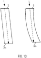
- the channel is substantially straight, in particular, the channel extends at an angle of 0 ° to 45 °, preferably 0 ° - 15 ° to a vertical longitudinal axis of the filling machine.
- substantially straight is meant in this application that the channel is either straight or the curvature or angulation of the channel is so small that the inlet of the collecting container can be at least partially recognized from the inspection opening, ie at least a straight beam path connecting the inspection opening with the inlet to the collecting container.
- the operator can easily see through from above through the channel to the sump.
- the evacuation opening is located in the pump cover. So far, the evacuation port was located mainly in the side wall of the pump housing. Due to a radial sealing gap between the vane and the vane pump casing, the rotor and the pump vane produce pasty mass in the evacuation area, i. H. the area in which the evacuation opening is arranged entrained. This entrained material then settles on the lateral pump wall in the evacuation area and closes with time the evacuation opening in the pump wall. In addition, pasty mass is dragged into the channel and sump. Consequently, the evacuation and thus the portion accuracy will be worse. According to the present invention, the evacuation port is now in the pump cover, d.
- the inspection opening is formed lockable.
- the inspection opening can be closed by means of a closure element and preferably also opened again.
- the closure element is designed as an axially movable piston.
- the closure element can also have a sight glass, so that the operator can inspect the channel and / or the collecting container even during a running process through the sight glass and immediately becomes aware of excessive contamination.
- the inspection opening is arranged in the upper region of a recess.
- This recess can be arranged for example in the cover of the vane pump and / or the pivot housing or the machine housing.
- the recess is opened through the inspection opening upwards and has a circumferential side wall, and an adjoining lower floor area.
- the channel preferably opens into the lower region of the recess, so that the inspection opening is connected to the channel via the recess.
- another channel section which is connected to the evacuation opening in the vane pump, preferably opens into the lower region of the recess.
- the further channel section is connected to the lower region of the recess, there is the advantage that the channel section and the evacuation opening can also be viewed from above via the inspection opening.
- the entire area from the evacuation port to the channel and preferably to the sump can be inspected.
- the piston is axially movably disposed in the recess, such that in a lower position it either closes the channel which is connected to the collecting container and / or closes the further channel portion, ie. H. separates the channel from the other channel section.
- the axially movable piston can also be completely removed from the recess so that, for example, the channel can be better inspected and cleaned. Furthermore, it is possible to move the axially movable piston so far upwards that the channel and the further channel section can be ventilated. When inserted, the piston seals the recess to the outside.
- the piston can preferably be moved axially manually, for example by means of a thread, bayonet closure, etc.
- a sensor is integrated in the closure element and / or in the lid of the vane pump, in particular for measuring the temperature and / or the pressure or the density or the air content, etc.
- an optical sensor can be integrated in the closure element, for example, the channel and / or the collecting container optically detected and displayed on a display.
- the further channel section and optionally the evacuation opening can be optically detected by this sensor.
- the sensor signals can be fed to the controller of the filling machine and evaluated there and thus serve for automatic process monitoring and optimization.
- the channel is at least partially formed of transparent material, for. B. as a transparent tube which is attached to the recess.
- the collection container is preferably formed at least partially of a transparent material.
- at least one illumination preferably LED emitter
- at least one illumination for illuminating the channel and / or the collecting container may be provided to the channel and / or the collecting container to illuminate from the outside. If the channel and / or collecting container illuminated from the outside, so impurities can be detected and detected particularly well and it results in a gap-free construction.
- a filling machine is preferably inspected with a closed lid of a vane pump via an inspection opening of the channel, and / or the collecting container.
- the inspection opening is preferably open upwards (or also obliquely upward).
- the channel can be cleaned through the inspection port. At the same time, if it is detected via the inspection opening that the collecting container is too full, the collecting container can be emptied.
- the evacuation opening and / or the channel section which is in connection with the evacuation opening can be inspected and cleaned by the inspection opening. That is, the inspection opening to the evacuation opening and / or the channel portion is arranged such that a free visibility is ensured from above. This also means that there is a straight beam path which connects the inspection opening with the evacuation opening or the channel section which is in communication with the evacuation opening.
- Fig. 1 shows roughly schematically a side view of a filling machine according to the present invention.
- the filling machine 1 has a funnel 18 for receiving pasty mass.
- This funnel 18 is, as well as off Fig. 2 emerges, arranged on a pivot housing 10 such that the pivot housing including a lid 9 of a vane pump 2 can be pivoted to open vane pump 2.
- the vane pump 2 is arranged below the funnel.
- the filling machine 1 further has a filling tube 19.
- the pasty mass is pushed by the vane pump 2 in the filling tube 19 and then ejected in a known manner, for example in sausage casings.
- the filling machine further comprises a controller 22, and a display 21.
- the filling machine still has a lifting device with a lift truck 20, can be lifted over the pasty mass and tilted into the hopper 18.
- the filling machine has a machine housing 11, in which the vane pump 2 is arranged.
- Fig. 2 shows the structure of the vane pump 2 in greater detail.
- the vane pump has a lateral housing wall 24 and a bottom plate 25 and is with the cover 9 upwards lockable. In the in Fig. 2 shown position, the vane pump is opened, for example, for cleaning purposes, so that the interior of the conveyor can be seen.
- rotatable rotor 28 In the interior 27 an eccentrically arranged, rotatable rotor 28 is provided. In the rotor 28 are the radially displaceable vanes 23, which form with the housing wall 24 of the vane pump, the bottom 25 and the cover 9 and the outer surface of the rotor 28 vane and cooperate in the sealing sense.
- the vane pump further has a sausage meat inlet 29 and a sausage meat outlet 31.
- a pressure region 30 adjoins, in which the vane cells 7 shrink in their volume. This pressure region opens into the sausage meat outlet 31, which leads to an outlet pipe, not shown.
- the ram outlet is followed in the direction of rotation A by a sealing region 32, in which the outer surface of the rotor 28 comes into direct contact with the inner wall of the pump housing.
- the sealing region is adjoined by the vacuum or suction region 33, which extends to the brewing inlet 29.
- a negative pressure is generated, which facilitates the filling of the pasty mass and serves to the fact that the pasty mass as much air can be withdrawn.
- an evacuation opening 8 is provided, via which by means of a vacuum pump 3, such as in Fig. 3 is shown, the vane 7 can be evacuated, ie, for example, the pressure in the vane cells is reduced.
- the evacuation opening 8 is arranged in the side wall 24 of the vane cell pump 2.
- the opened lid 9 is not shown for simplicity.
- a channel 6 is connected to the evacuation opening 8 and opens into a collecting container 4 for entrained pasty mass. In the collecting container entrained pasty mass, dirt and water can be collected. Even when cleaning the vane pump components of the pumped mass advised in this container.
- the vacuum pump 3 and an optional air filter 34 which is connected via a line 35 to the sump 4, can be effectively protected.
- the level in the collecting container 4 must not become so high that the openings 36a and 36b clog towards the channel 6 or to the line 35 to the air filter, otherwise no more vacuum can be generated in the vane 7.
- the channel 6 may not strong soiling or clogging to ensure that sufficient vacuum is created. So far, it has been very difficult to inspect the contamination of channel 6.
- the level, or the degree of contamination of the collecting container 4 could only be inspected by switching off the vacuum on the machine and the cover flap of the collecting container on the machine housing 11 opened.
- an inspection opening 5 is now provided, which is connected via a channel 6 to the collecting container 4, for inspecting the channel and / or the collecting container.
- the interior of the channel 6 can be inspected via the inspection opening 5, the visibility is given through the channel to the sump 4.
- the channel should be substantially straight, especially at an angle of 0 °. to branch off from the side wall 24 of the vane pump 2 to 15 ° to the vertical longitudinal axis of the filling machine.
- the inspection opening 5 viewed in the vertical direction, advantageously arranged in the upper half, or in the upper third of the side wall 24 to ensure good visibility.
- the channel 6 is at least partially formed of transparent material, for. B. as a transparent tube and / or the collecting container is at least partially formed of a transparent material, such that light from the outside can shine through the material.
- at least one illumination 37 for example in the form of an LED spotlight, illuminate the channel 6 and / or the collecting container 4 from the outside. If channel 6 and / or the collecting container 4 are illuminated from the outside, impurities can be detected and recognized particularly well. For example, if the channel 6 is clogged, a dark spot appears.
- a camera 38 (eg in a recess in a position above the highest level in the collecting container 4) may be arranged to receive the interior of the collecting container 4 and, for example, on a display, for. B. Display 21, represent. This allows for additional monitoring.
- the lighting device is, for example, an LED spotlight.
- the inspection opening 5 is located in the side wall 24 of the vane pump 2. This has the disadvantage that for inspecting and cleaning the channel 6, the cover 9 of the vane pump must be opened.
- the following embodiments essentially correspond to those in FIG Fig. 3 embodiment shown with the exception that the inspection opening is not located inside the vane pump 2, but outside the vane pump and directed outwards, preferably upwards.
- Fig. 4 shows a corresponding partial longitudinal section of a filling machine according to such an embodiment.
- 27 schematically shows the chamber or the interior of the vane pump, which is closed by the cover 9 here.
- the pivot housing 10 Above the lid, the pivot housing 10 is arranged.
- the upwardly facing inspection opening 5 is provided in the pivot housing 10.
- the inspection opening 5 is provided here in the upper region of a recess 13, which is formed in the pivot housing 10.
- the recess 13 could also extend into the cover 9.
- the channel 6 extends here from the water separator 4 through the housing wall 24 of the vane pump, the cover 9 and opens into the lower region 13b of the recess 13.
- the recess 13 may be formed, for example, a hollow cylinder, but is not limited to this form.
- the evacuation opening 8 is not provided here in the side wall 24, but in the lid 9. From the evacuation 8, another channel section 14 extends to the recess 13 and also opens into the lower region. According to the present invention, the evacuation opening 8 is now in the pump cover 9, d. h., That is sucked up or the vane cells are vented upward and is sucked through the pump cover 9. Whenever a wing 23 passes under the evacuation opening 8, the pasty mass, if something has been deposited on the pump cover, taken from the pump wing and thus kept the hole free.
- the channel 6 is thus connected via the recess 13 and the portion 14 with the vane, ie the evacuation 8.
- the interior of the channel 6 and also of the collecting container 4 can be inspected via the inspection opening 5.
- the degree of contamination Inspect a simple way, without the cover or lid 9 and swivel housing 10 must be opened.
- a cleaning of the channel 6 is possible - for example, with a brush and or cleaning liquid without opening the lid 9, so that it is not necessary that the funnel is emptied.
- the evacuation opening 8 and the channel section 14 are arranged such that this area can also be inspected via the inspection opening 5 without the vane pump having to be opened. It would also be possible for the channel 6 and / or the channel section 14 not to open into the lower region, in this case the bottom, but open laterally into the recess at an angle such that from the inspection opening into the channel 6, preferably into the collecting container and / or in the channel section 14 can be viewed preferably to the evacuation opening.
- the inspection opening 5 is formed lockable.
- the inspection opening can be closed by means of a closure element 12, in particular from Fig. 5 which describes a further embodiment of the present invention which essentially corresponds to that in Fig. 4 shown embodiment corresponds.
- the closure element is designed here as an axially movable piston 12.
- the axially movable closure piston is designed as a vacuum closure and closes here the inspection opening 5.
- a closure cylinder 16 is provided, which separates the channel 6 from the evacuation port 8, such that there is no more vacuum connection between the vacuum pump and the conveyor.
- the closure cylinder 16 is here in the lower region of the lid 9.
- a corresponding closure can also be made from above or from the side.
- the actuation of the locking cylinder can be done electrically, pneumatically or hydraulically. It is only essential that the closure cylinder closes the channel 6.
- At least one sensor 17a can be provided for measuring the pressure or the temperature or the fill level.
- a sensor or such sensors 17b may additionally or alternatively also be arranged in the pump cover 9 in the vacuum or suction region of the vane pump.
- Appropriate Sensor signals can be fed to the controller 22 of the filling machine where they are evaluated and used for automatic process monitoring and optimization.
- a corresponding pressure sensor 17a which is easy to disassemble and clean, can effectively monitor the function of the evacuation system between the vacuum pump 3 and the closure piston.
- the sensor 17b is able to monitor the real pressure conditions in the suction region of the vane pump.
- Fig. 6 shows that in Fig. 5 shown embodiment with closed lock cylinder 16.
- the lock cylinder 16 is here in its upper position, so that the vacuum connection between the sump and vane pump is shut off.
- Fig. 7 shows the in Fig. 5 and 6 shown embodiments, in which case the closure piston 12 has been moved upwards and is in a ventilation position.
- the lock cylinder releases the path from the channel 6 in the direction of the inspection opening 5 here.
- Fig. 8 corresponds to the in Fig. 5 to 7 shown embodiment, in which case the closure piston 12 has been removed for inspection and cleaning. How clear from the Fig. 8 It can be seen that free visibility from the inspection opening 5 through the channel 6 to the collecting container 4 is also given from above. That is, there is a beam path connecting the inspection port 5 to the inlet 36a to the sump 4. The operator can thus easily recognize whether the channel 6 is dirty or clogged and whether the sump 4 is too full.
- Fig. 9 shows a cross section through an embodiment according to the present invention.
- the Fig. 10 corresponds to a sectional view along the line II in FIG Fig. 9 ,
- This embodiment substantially corresponds to the previous embodiments, wherein here in the closure element 12 as a pressure sensor, a height-adjustable plunger 40 is provided.
- This plunger 40 is used for optical monitoring of the pressure conditions.
- This plunger changes its vertical position as a function of the pressure in the vacuum region, ie in the suction area of the conveyor and in the channel 6.
- the plunger 40 is held by a prestressed spring in a certain position (in which the vacuum area is not closed, ie the channel 41 with the outside atmosphere is connected).
- the sensor 17a is connected via a line 41 with the Vacuum system connected.
- the plunger 40 Under negative pressure, the plunger 40 is drawn into the closure element and terminates flush with its surface, ie closes the vacuum region. If the set vacuum is reached, the channel 41 is closed. With increasing pressure of the plunger, similar to the pressure display in a pressure cooker, pushed upwards and protrudes from the closure element 12 to the top Klippet pressure drop occurs if necessary, for example, red marked plunger out of the closure element.
- the evacuation opening 8 is advantageously integrated in the pump cover 9.
- the principle of free visibility is also realized when the evacuation port 8 is provided in a side wall 24 of the vane pump and a corresponding channel portion 14 which is connected to the evacuation port, either directly into the channel 6 or z. B. opens into a recess 13.
- Fig. 11 shows a corresponding arrangement in which the evacuation opening 8 is arranged in the housing wall 24.
- the inspection opening 5 is not arranged in the cover 9 or the pivot housing 10, but in the machine housing 11, ie here the top or the side wall of the machine housing 11.
- a housing portion 42 at the top Wall of the machine housing 11 is arranged, in which case the recess 13 is formed in the housing portion 42.
- the vacuum pump 3 is connected to the conveyor via the collecting container 4, the channel 6, the recess 13, the further channel section 14 and the evacuation opening 8.
- the vacuum connection between the vacuum pump and vane pump can be interrupted by the piston 12.
- a separate closure piston 16 can also be provided here to separate the vacuum path between the vacuum pump and vane pump.
- the channel 6 and the collecting container 4 can be inspected and also easily cleaned with the pistons 12 removed.
- Fig. 12a shows the in Fig. 11 shown arrangement with inclined channel 14.
- the channel portion 14 is still visible from above the inspection opening 5.
- the inspection opening is laterally adjacent to the vane pump 2, as in FIG. 11 , As well as in FIG. 11 , can here from a position above the surface 50 of the machine housing 11 from both the channel section 14 and the channel 6 and the collecting container are inspected.
- FIG. 12b It is also possible that the plane in which the inspection opening 5 is located at an angle to the horizontal plane. This also applies to all other embodiments. Again, from a position above the surface 50 of the machine housing, the channel section 14, the channel 6 and the collecting container 4 can be inspected. Due to the inclination of the inspection opening 5 or the surface of the machine housing in this area, the channel section 14 is even better to inspect.
- the inspection opening, resp. the plane in which the inspection opening is located, for example, is inclined at an angle of greater than 0 ° and less than 45 ° to the horizontal plane.
- the soiling state of the collecting container 4 of the filling machine, or at least the channel 6, can be inspected.
Landscapes
- Engineering & Computer Science (AREA)
- Life Sciences & Earth Sciences (AREA)
- Food Science & Technology (AREA)
- Wood Science & Technology (AREA)
- Zoology (AREA)
- Mechanical Engineering (AREA)
- General Engineering & Computer Science (AREA)
- Nutrition Science (AREA)
- Chemical & Material Sciences (AREA)
- Polymers & Plastics (AREA)
- Health & Medical Sciences (AREA)
- Processing Of Meat And Fish (AREA)
- Sampling And Sample Adjustment (AREA)
Description
Die Erfindung betrifft eine Füllmaschine sowie ein Verfahren zum Überwachen des Verschmutzungszustands eines Sammelbehälters und /oder eines Kanals mit dem der Sammelbehälter verbunden ist einer solchen Füllmaschine gemäß den Oberbegriffen der Ansprüche 1 und 16.The invention relates to a filling machine and a method for monitoring the contamination state of a collecting container and / or a channel with which the collecting container is connected to such a filling machine according to the preambles of
Eine Füllmachine sowie ein Verfahren gemäß den Oberbegriffen der Ansprüche 1 und 16 sind bereits aus der
Bei der Wurstherstellung wird mit Hilfe einer Füllmaschine pastöse Masse über einen Trichter und eine Flügelzellenpumpe in ein Füllrohr geschoben, wobei die pastöse Masse dann beispielsweise aus dem Füllrohr in eine Wursthülle ausgestoßen wird. Um Lebensmittel, insbesondere pastöse Masse, wie Brät, haltbar zu machen, wird diesen Massen möglichst viel Luft entzogen. Dazu wird eine Vakuumpumpe an die Flügelzellenpumpe für die pastöse Masse angeschlossen, um die Flügelzellen der Flügelzellenpumpe zu evakuieren. Entsprechende Füllmaschinen bzw. Flügelzellenpumpen sind beispielsweise in der
Beim Evakuieren der Förderzellen kommt es jedoch vor, dass Bestandteile der pastösen Masse in Richtung Vakuumpumpe mitgerissen werden. Aus diesem Grund ist ein Sammelbehälter zwischen Förderpumpe und Vakuumpumpe vorgesehen, um mitgerissene pastöse Masse, Schmutz und Wasser zu sammeln. Auch beim Reinigen der Flügelzellenpumpe geraten Bestandteile der geförderten Masse, Wasser und Schmutz in diesen Sammelbehälter. Somit kann die Vakuumpumpe und auch ein davor geschalteter Luftfilter geschützt werden.When evacuating the delivery cells, however, it happens that components of the pasty mass are entrained in the direction of the vacuum pump. For this reason, a collecting tank between the feed pump and vacuum pump is provided to collect entrained pasty mass, dirt and water. Even when cleaning the vane pump components of the pumped mass, water and dirt get into this container. Thus, the vacuum pump and also a previously connected air filter can be protected.
Der Sammelbehälter muss in regelmäßigen Zeitabständen geleert und gereinigt werden, um die Ausbreitung von krankheitserregenden Organismen und unangenehmen Gerüchen zu verhindern. Außerdem muss verhindert werden, dass die im Sammelbehälter gesammelte Masse einen bestimmten Füllstand übersteigt, d. h., dass verhindert werden muss, dass die Vakuumverbindung von der Förderpumpe zur Vakuumpumpe unterbrochen wird (wenn beispielsweise die gesammelte Masse den Sammelbehälter vollständig füllt und bereits in die Vakuumleitungen aufsteigt, so dass die Vakuumleitungen verstopfen). Sonst kommt es zu einem unerwünschten Druckanstieg in den Förderzellen. Darüber hinaus muss auch der Vakuumkanal zwischen Förderwerk und Sammelbehälter regelmäßig gereinigt werden.The collection container must be emptied and cleaned at regular intervals to prevent the spread of pathogenic organisms and unpleasant odors. In addition, it must be prevented that the mass collected in the collecting tank exceeds a certain level, ie that it must be prevented that the vacuum connection from the feed pump to the vacuum pump is interrupted (for example, if the collected mass completely fills the sump and already rises in the vacuum lines, so that the vacuum lines clog). Otherwise there will be an undesirable pressure increase in the delivery cells. In addition, the vacuum channel between the conveyor and the collecting tank must be cleaned regularly.
Bei den herkömmlichen Füllmaschinen ist es im betriebsbereiten Zustand nicht möglich den Vakuumkanal zu inspizieren um zum richtigen Zeitpunkt zu entscheiden, ob der Vakuumkanal gereinigt werden muss.With the conventional filling machines, it is not possible to inspect the vacuum channel when it is ready for operation in order to decide at the right time whether the vacuum channel needs to be cleaned.
Die Zugänglichkeit zum Vakuumkanal ist bisher nur von der Oberseite des geöffneten Förderwerks möglich. Das heißt, dass, wenn ein z. B. verstopfter Vakuumkanal gereinigt werden muss, zunächst der Fülltrichter der Füllmaschine entleert werden muss, um dann das Schwenkgehäuse, an dem der Fülltrichter befestigt ist und an dessen unterem Ende sich der Deckel der Flügelzellenpumpe befindet, nach oben zu klappen. Eine Kontrolle des Vakuumkanals ist kaum möglich, eine Kontrolle des Sammelbehälters ist umständlich, da hier z.B. der Sammelbehälter hinter einer Klappe zu inspizieren ist, wobei zur Inspektion das Vakuum abzuschalten ist. Selbst bei geöffneter Flügelzellenpumpe kann der Vakuumkanal und/oder der Sammelbehälter nicht ausreichend kontrolliert werden.The accessibility to the vacuum channel is previously possible only from the top of the open conveyor. This means that if a z. B. clogged vacuum duct must be cleaned, first the hopper of the filling machine must be emptied, then the swing housing to which the hopper is attached and at the lower end, the lid of the vane pump is to fold up. A control of the vacuum channel is hardly possible, a control of the collecting container is cumbersome, since here e.g. the collecting container is to be inspected behind a flap, with the vacuum to be switched off for inspection. Even with the vane pump open, the vacuum channel and / or the collecting container can not be adequately controlled.
Hiervon ausgehend liegt der vorliegenden Erfindung die Aufgabe zugrunde, auf einfache Art und Weise den Vakuumkanal und/oder den Sammelbehälter zu inspizieren und zu reinigen.On this basis, the present invention has the object to inspect the vacuum channel and / or the collecting container in a simple manner and clean.
Erfindungsgemäß wird die Aufgabe durch die Merkmale der Ansprüche 1 und 16 gelöst.According to the invention the object is achieved by the features of
Die erfindungsgemäße Füllmaschine zum Herstellen von Würsten weist eine Flügelzellenpumpe zum Fördern pastöser Masse auf, sowie eine Vakuumpumpe zum Erzeugen eines Unterdrucks in Flügelzellen der Flügelzellenpumpe. Die Flügelzellenpumpe ist über einen Sammelbehälter mit der Vakuumpumpe verbunden. Der Sammelbehälter dient dazu, mitgerissene pastöse Masse und Flüssigkeiten zu sammeln. Die Füllmaschine weist eine vorzugsweise nach oben oder schräg nach oben gerichtete Inspektionsöffnung auf, die über einen Kanal mit dem Sammelbehälter verbunden ist zum Inspizieren des Kanals und/oder des Sammelbehälters. D.h. die Inspektionsöffnung kann in einer Horizontalebene aber auch in einer Ebene, die zur Horizontalebene geneigt ist, liegen, z.B. unter einem Winkel von 0° - 45°, insbesondere 0° - 15°.The filling machine according to the invention for producing sausages has a vane pump for conveying pasty mass, as well as a vacuum pump for generating a negative pressure in vane cells of the vane pump. The vane pump is connected via a collecting container with the vacuum pump. The collection container serves to collect entrained pasty mass and liquids. The filling machine has a preferably upwardly or obliquely upward inspection opening, which is connected via a channel with the collecting container for inspecting the channel and / or the collecting container. That the inspection opening may lie in a horizontal plane but also in a plane which is inclined to the horizontal plane, e.g. at an angle of 0 ° - 45 °, in particular 0 ° - 15 °.
Das bedeutet, dass vorzugsweise die von oben frei einsehbare Inspektionsöffnung ermöglicht, den Kanal und/oder den Sammelbehälter auf Verschmutzung zu überprüfen, ohne dass das Flügelzellenförderwerk oder eine Klappe zum Sammelbehälter geöffnet werden muss. Von oben bedeutet hier aus einer Position oberhalb der Flügelzellenpumpe bzw. des Maschinengehäuses. Somit kann auf einfache Art und Weise der Verschmutzungsgrad des Kanals und/oder des Sammelbehälters ermittelt werden. Darüber hinaus bietet die Inspektionsöffnung auch einen Zugang zu dem Kanal, um den Kanal bei Bedarf zu reinigen, ohne dass aufwändige Maßnahmen notwendig sind.This means that the inspection opening, which is freely visible from above, preferably makes it possible to check the channel and / or the collection container for contamination without having to open the vane cell conveyor or a flap to the collection container. From above here means from a position above the vane pump or the machine housing. Thus, the degree of contamination of the channel and / or the collecting container can be determined in a simple manner. In addition, the inspection opening also provides access to the channel to clean the channel when needed, without the need for elaborate measures.
Vorteilhafterweise steht der Kanal mit einer Evakuierungsöffnung in der Flügelzellenpumpe in Verbindung. Das bedeutet, dass der Kanal der Vakuumkanal ist, über den die Flügelzellen der Flügelzellenpumpe evakuiert werden oder zumindest ein Teil dieses Vakuumkanals bzw. dieser Vakuumverbindung ist. Die Inspektionsöffnung kann entweder innerhalb des Innenraums der Flügelzellenpumpe angeordnet sein oder vorzugsweise außerhalb.Advantageously, the channel communicates with an evacuation port in the vane pump. This means that the channel is the vacuum channel through which the vane cells of the vane pump are evacuated or at least part of this vacuum channel or this Vacuum connection is. The inspection opening may be located either within the interior of the vane pump or preferably outside.
Vorteilhafterweise ist die Inspektionsöffnung außerhalb des Innenraums der Flügelzellenpumpe angeordnet. So sind der Kanal und/oder der Sammelbehälter von einer Position oberhalb des geschlossenen Deckels der Flügelzellenpumpe durch die Inspektionsöffnung frei einsehbar.Advantageously, the inspection opening is arranged outside the interior of the vane pump. Thus, the channel and / or the collecting container from a position above the closed lid of the vane pump through the inspection opening are freely visible.
D.h., dass die Flügelzellenpumpe zum Überprüfen der Verschmutzung nicht geöffnet werden muss, so dass beispielsweise ein Deckel der Flügelzellenpumpe zusammen mit einem Schwenkgehäuse und einem darauf angeordneten Trichter nicht verschwenkt werden muss. Ein wesentlicher Vorteil besteht auch darin, dass der Kanal und/oder Sammelbehälter inspiziert und gereinigt werden können, ohne dass der Trichter dazu geleert werden muss.That is, the vane pump does not need to be opened for checking the fouling, so that, for example, a lid of the vane pump need not be pivoted together with a pivot housing and a hopper disposed thereon. A significant advantage is also that the channel and / or collecting container can be inspected and cleaned without the funnel has to be emptied.
Gemäß einer bevorzugten Ausführungsform der vorliegenden Erfindung ist die Inspektionsöffnung z. B. in einem Deckel der Flügelzellenpumpe angeordnet. Dies ist dann der Fall, wenn bei bestimmten Maschinentypen das Schwenkgehäuse, auf dem der Vakuumtrichter angeordnet ist und an dessen Unterseite der Deckel befestigt ist, kleiner ist als der Deckel, derart, dass der Deckel über das Schwenkgehäuse vorsteht. Es ist aber auch möglich, dass die Inspektionsöffnung sich im Schwenkgehäuse befindet, und sich dann eine Aussparung von der Inspektionsöffnung durch das Schwenkgehäuse und den Deckel zu dem Kanal erstreckt. Alternativ ist es auch möglich, dass sich die Inspektionsöffnung in dem Maschinengehäuse befindet, d. h. in der Oberfläche der Füllmaschine seitlich neben dem Deckel und dem Schwenkgehäuse. Alle zuvor genannten Ausführungsformen ermöglichen, dass der Kanal und/oder der Sammelbehälter vorteilhafterweise bei geschlossenem Deckel durch die Inspektionsöffnung inspizierbar sind.According to a preferred embodiment of the present invention, the inspection opening z. B. arranged in a cover of the vane pump. This is the case when in certain types of machines, the pivot housing on which the vacuum hopper is arranged and on the underside of the lid is fixed, is smaller than the lid, such that the lid protrudes beyond the pivot housing. But it is also possible that the inspection opening is located in the pivot housing, and then extends a recess from the inspection opening through the pivot housing and the lid to the channel. Alternatively, it is also possible that the inspection opening is located in the machine housing, d. H. in the surface of the filling machine laterally next to the lid and the pivot housing. All of the aforementioned embodiments enable the channel and / or the collecting container to be advantageously inspected through the inspection opening when the lid is closed.
Vorteilhafterweise ist eine freie Einsehbarkeit von der Inspektionsöffnung durch den Kanal vorzugsweise bis zum Sammelbehälter gegeben.Advantageously, a free visibility of the inspection opening through the channel is preferably given to the collection container.
Dabei ist der Kanal im Wesentlichen gerade ausgebildet, insbesondere verläuft der Kanal unter einem Winkel von 0° bis 45° vorzugsweise 0° - 15° zu einer vertikalen Längsachse der Füllmaschine. Unter "im Wesentlichen gerade" versteht man in dieser Anmeldung, dass der Kanal entweder gerade ist oder aber die Krümmung oder Verwinkelung des Kanals so klein ist, dass von der Inspektionsöffnung aus der Einlass des Sammelbehälters zumindest teilweise erkannt werden kann, d. h., dass es zumindest einen geraden Strahlengang gibt, der die Inspektionsöffnung mit dem Einlass zum Sammelbehälter verbindet. Somit kann der Bediener einfach von oben durch den Kanal bis zum Sammelbehälter durchschauen.In this case, the channel is substantially straight, in particular, the channel extends at an angle of 0 ° to 45 °, preferably 0 ° - 15 ° to a vertical longitudinal axis of the filling machine. By "substantially straight" is meant in this application that the channel is either straight or the curvature or angulation of the channel is so small that the inlet of the collecting container can be at least partially recognized from the inspection opening, ie at least a straight beam path connecting the inspection opening with the inlet to the collecting container. Thus, the operator can easily see through from above through the channel to the sump.
Gemäß einer bevorzugten Ausführungsform befindet sich die Evakuierungsöffnung im Pumpendeckel. Bislang befand sich die Evakuierungsöffnung hauptsächlich in der Seitenwandung des Pumpengehäuses. Bedingt durch einen radialen Dichtspalt zwischen Flügel und Flügelzellenpumpengehäuse wird vom Rotor sowie dem Pumpflügel pastöse Masse in den Evakuierungsbereich, d. h. den Bereich, in dem die Evakuierungsöffnung angeordnet ist, mitgeschleppt. Dieses mitgeschleppte Material setzt sich dann an der seitlichen Pumpenwand im Evakuierungsbereich ab und verschließt mit der Zeit die Evakuierungsöffnung in der Pumpenwand. Darüber hinaus wird pastöse Masse in den Kanal und Sammelbehälter mitgeschleppt. Folglich wird die Evakuierung und somit auch die Portionsgenauigkeit schlechter. Gemäß der vorliegenden Erfindung befindet sich nun die Evakuierungsöffnung im Pumpendeckel, d. h., dass nach oben abgesaugt wird, bzw. die Flügelzellen nach oben hin entlüftet werden, wobei durch den Pumpendeckel abgesaugt wird. Immer wenn ein Pumpenflügel unter der Evakuierungsöffnung durchfährt wird die pastöse Masse, falls doch etwas am Pumpendeckel abgelagert wurde, vom Pumpenflügel mitgenommen und die Bohrung somit freigehalten. Das Freihalten der Evakuierungsöffnung am Pumpendeckel ist möglich, weil der Spalt zwischen Pumpenflügel und Pumpendeckel deutlich kleiner ist als der radiale Spalt zwischen Pumpenwand und Pumpenflügel. Somit wird ein Verstopfen der Evakuierungsbohrung durch mitgeschlepptes Brät vermieden.According to a preferred embodiment, the evacuation opening is located in the pump cover. So far, the evacuation port was located mainly in the side wall of the pump housing. Due to a radial sealing gap between the vane and the vane pump casing, the rotor and the pump vane produce pasty mass in the evacuation area, i. H. the area in which the evacuation opening is arranged entrained. This entrained material then settles on the lateral pump wall in the evacuation area and closes with time the evacuation opening in the pump wall. In addition, pasty mass is dragged into the channel and sump. Consequently, the evacuation and thus the portion accuracy will be worse. According to the present invention, the evacuation port is now in the pump cover, d. h., That is sucked upwards, or the vane cells are vented upwards, being sucked through the pump cover. Whenever a pump blade passes under the evacuation opening, the pasty mass, if something has been deposited on the pump cover, taken from the pump blade and thus kept the bore free. Keeping the evacuation port at the pump cover is possible because the gap between the pump blade and the pump cover is significantly smaller than the radial gap between the pump wall and the pump blade. Thus, a clogging of the evacuation hole is avoided by entrained sausage meat.
Die Inspektionsöffnung ist verschließbar ausgebildet. Die Inspektionsöffnung kann mit Hilfe eines Verschlusselements verschlossen und vorzugsweise auch wieder geöffnet werden. Vorzugsweise ist das Verschlusselement als axial beweglicher Kolben ausgebildet. Das Verschluss-element kann auch ein Schauglas aufweisen, so dass der Bediener auch während eines laufenden Prozesses durch das Schauglas den Kanal und/oder den Sammelbehälter inspizieren kann und sofort auf übermäßige Verschmutzungen aufmerksam wird.The inspection opening is formed lockable. The inspection opening can be closed by means of a closure element and preferably also opened again. Preferably, the closure element is designed as an axially movable piston. The closure element can also have a sight glass, so that the operator can inspect the channel and / or the collecting container even during a running process through the sight glass and immediately becomes aware of excessive contamination.
Gemäß einer bevorzugten Ausführungsform ist die Inspektionsöffnung im oberen Bereich einer Aussparung angeordnet. Diese Aussparung kann beispielsweise im Deckel der Flügelzellenpumpe und/oder dem Schwenkgehäuse oder aber dem Maschinengehäuse angeordnet sein. Die Aussparung ist durch die Inspektionsöffnung nach oben geöffnet und weist eine umlaufende Seitenwandung auf, sowie einen sich daran anschließenden unteren Bodenbereich. Der Kanal mündet vorzugsweise in den unteren Bereich der Aussparung, so dass die Inspektionsöffnung über die Aussparung mit dem Kanal verbunden ist. Vorteilhafterweise mündet auch ein weiterer Kanalabschnitt, der mit der Evakuierungsöffnung in der Flügelzellenpumpe verbunden ist vorzugsweise in den unteren Bereich der Aussparung. Somit ist die Flügelzellenpumpe über die Evakuierungsöffnung, den weiteren Kanalabschnitt, die Aussparung und den Kanal mit dem Sammelbehälter verbunden.According to a preferred embodiment, the inspection opening is arranged in the upper region of a recess. This recess can be arranged for example in the cover of the vane pump and / or the pivot housing or the machine housing. The recess is opened through the inspection opening upwards and has a circumferential side wall, and an adjoining lower floor area. The channel preferably opens into the lower region of the recess, so that the inspection opening is connected to the channel via the recess. Advantageously, another channel section, which is connected to the evacuation opening in the vane pump, preferably opens into the lower region of the recess. Thus, the vane pump via the evacuation port, the further channel portion, the recess and the channel is connected to the collecting container.
Wenn auch der weitere Kanalabschnitt mit dem unteren Bereich der Aussparung verbunden ist, so ergibt sich der Vorteil, dass auch der Kanalabschnitt und die Evakuierungsöffnung von oben über die Inspektionsöffnung einsehbar sind. Somit kann bei geöffnetem Förderwerk der gesamte Bereich von der Evakuierungsöffnung bis zum Kanal und vorzugsweise bis zum Sammelbehälter inspiziert werden.Although the further channel section is connected to the lower region of the recess, there is the advantage that the channel section and the evacuation opening can also be viewed from above via the inspection opening. Thus, with the conveyor open, the entire area from the evacuation port to the channel and preferably to the sump can be inspected.
Vorteilhafterweise ist der Kolben in der Aussparung axial beweglich angeordnet, derart, dass er in einer unteren Position entweder den Kanal, der mit dem Sammelbehälter verbunden ist und/oder den weiteren Kanalabschnitt verschließt, d. h. den Kanal von dem weiteren Kanalabschnitt abtrennt.Advantageously, the piston is axially movably disposed in the recess, such that in a lower position it either closes the channel which is connected to the collecting container and / or closes the further channel portion, ie. H. separates the channel from the other channel section.
Der axial bewegliche Kolben kann auch komplett aus der Aussparung entfernt werden, damit beispielsweise der Kanal besser inspiziert und gereinigt werden kann. Ferner ist es möglich, den axial beweglichen Kolben so weit nach oben zu bewegen, dass der Kanal und der weitere Kanalabschnitt belüftet werden können. Im eingesetzten Zustand dichtet der Kolben die Aussparung nach außen ab. Der Kolben kann vorzugsweise manuell axial bewegt werden, beispielsweise mit Hilfe eines Gewindes, Bajonettverschlusses, etc..The axially movable piston can also be completely removed from the recess so that, for example, the channel can be better inspected and cleaned. Furthermore, it is possible to move the axially movable piston so far upwards that the channel and the further channel section can be ventilated. When inserted, the piston seals the recess to the outside. The piston can preferably be moved axially manually, for example by means of a thread, bayonet closure, etc.
Es ist aber auch möglich, einen angetriebenen Verschlusszylinder vorzusehen, der die Vakuumverbindung zwischen Vakuumpumpe und der Flügelzellenpumpe trennt, wobei der Verschlusszylinder vorzugsweise von einer Position in Vertikalrichtung betrachtet unterhalb des Deckels in den Kanal eingefahren wird .But it is also possible to provide a driven closure cylinder which separates the vacuum connection between the vacuum pump and the vane pump, wherein the closure cylinder is preferably retracted from a position in the vertical direction below the lid into the channel.
Gemäß einer bevorzugten Ausführungsform ist im Verschlusselement und / oder im Deckel der Flügelzellenpumpe ein Sensor integriert, insbesondere zum Messen der Temperatur und / oder des Drucks oder der Dichte oder des Luftgehalts etc. Auch ein optischer Sensor kann im Verschlusselement integriert sein, der beispielsweise den Kanal und/oder den Sammelbehälter optisch erfasst und auf einem Display darstellt. Gemäß einer bevorzugten Ausführungsform kann auch der weitere Kanalabschnitt und gegebenenfalls die Evakuierungsöffnung optisch von diesem Sensor erfasst werden. Die Sensorsignale können der Steuerung der Füllmaschine zugeführt und dort ausgewertet werden und somit zur automatischen Prozessüberwachung und Optimierung dienen.According to a preferred embodiment, a sensor is integrated in the closure element and / or in the lid of the vane pump, in particular for measuring the temperature and / or the pressure or the density or the air content, etc. Also, an optical sensor can be integrated in the closure element, for example, the channel and / or the collecting container optically detected and displayed on a display. According to a preferred embodiment, the further channel section and optionally the evacuation opening can be optically detected by this sensor. The sensor signals can be fed to the controller of the filling machine and evaluated there and thus serve for automatic process monitoring and optimization.
Vorteilhafterweise ist der Kanal zumindest abschnittsweise aus transparentem Material ausgebildet, z. B. als transparenter Schlauch, der an der Aussparung befestigt ist. Auch der Sammelbehälter ist vorzugsweise zumindest teilweise aus einem transparenten Material ausgebildet. Dann kann mindestens eine Beleuchtung (vorzugsweise LED -Strahler) zum Beleuchten des Kanals und/oder des Sammelbehälters vorgesehen werden, um den Kanal und/oder den Sammelbehälter von außen zu beleuchten. Werden der Kanal und/oder Sammelbehälter von außen beleuchtet, so können Verunreinigungen besonders gut erfasst und erkannt werden und es ergibt sich eine spaltfreie Konstruktion.Advantageously, the channel is at least partially formed of transparent material, for. B. as a transparent tube which is attached to the recess. Also, the collection container is preferably formed at least partially of a transparent material. Then, at least one illumination (preferably LED emitter) for illuminating the channel and / or the collecting container may be provided to the channel and / or the collecting container to illuminate from the outside. If the channel and / or collecting container illuminated from the outside, so impurities can be detected and detected particularly well and it results in a gap-free construction.
Gemäß dem erfindungsgemäßen Verfahren zum Überwachen des Verschmutzungszustands eines Sammelbehälters und/oder eines Kanals über den der Sammelbehälter mit der Inspektionsöffnung verbunden ist, einer Füllmaschine wird vorzugsweise bei geschlossenem Deckel einer Flügelzellenpumpe über eine Inspektionsöffnung der Kanal, , und/oder der Sammelbehälter inspiziert. Die Inspektionsöffnung ist vorzugsweise nach oben (oder auch schräg nach oben) geöffnet.According to the inventive method for monitoring the contamination state of a collecting container and / or a channel through which the collecting container is connected to the inspection opening, a filling machine is preferably inspected with a closed lid of a vane pump via an inspection opening of the channel, and / or the collecting container. The inspection opening is preferably open upwards (or also obliquely upward).
Der Kanal kann, wenn festgestellt wird, dass der Kanal zu stark verschmutzt ist, über die Inspektionsöffnung gereinigt werden. Gleichzeitig kann, wenn über die Inspektionsöffnung erfasst wird, dass der Sammelbehälter zu voll ist, der Sammelbehälter geleert werden.If the channel is found to be excessively dirty, the channel can be cleaned through the inspection port. At the same time, if it is detected via the inspection opening that the collecting container is too full, the collecting container can be emptied.
Gemäß einem bevorzugten Ausführungsbeispiel ist durch die Inspektionsöffnung auch die Evakuierungsöffnung und/oder der Kanalabschnitt der in Verbindung mit der Evakuierungsöffnung steht, inspizierbar und reinigbar. Das heißt, dass die Inspektionsöffnung zur Evakuierungsöffnung und/oder dem Kanalabschnitt derart angeordnet ist, dass eine freie Einsehbarkeit von oben gewährleistet ist. Das heißt auch, dass es einen geraden Strahlengang gibt, der die Inspektionsöffnung mit der Evakuierungsöffnung oder dem Kanalabschnitt, der in Verbindung mit der Evakuierungsöffnung steht, verbindet.According to a preferred embodiment, the evacuation opening and / or the channel section which is in connection with the evacuation opening can be inspected and cleaned by the inspection opening. That is, the inspection opening to the evacuation opening and / or the channel portion is arranged such that a free visibility is ensured from above. This also means that there is a straight beam path which connects the inspection opening with the evacuation opening or the channel section which is in communication with the evacuation opening.
Die Erfindung wird nachfolgend unter Bezugnahme der folgenden Figuren näher erläutert.
- Fig. 1
- zeigt grob schematisch eine Seitenansicht einer Füllmaschine gemäß einem Ausführungsbeispiel der vorliegenden Erfindung.
- Fig. 2
- zeigt schematisch in perspektivischer Darstellung eine Flügelzellenpumpe.
- Fig. 3
- zeigt grob schematisch eine erste Ausführungsform der vorliegenden Erfindung.
- Fig. 4
- zeigt grob schematisch einen Schnitt durch einen Teil einer Füllmaschine gemäß einem zweiten Ausführungsbeispiel der vorliegenden Erfindung.
- Fig. 5
- zeigt einen Längsschnitt durch einen Teil einer Füllmaschine gemäß einem dritten Ausführungsbeispiel gemäß der vorliegenden Erfindung in Evakuierposition.
- Fig. 6
- zeigt das in
Fig. 5 gezeigte Ausführungsbeispiel mit geschlossenen Verschlusszylinder. - Fig. 7
- zeigt die in
Fig. 5 und6 gezeigten Ausführungsbeispiele mit geöffnetem Verschluss in Belüftungsposition. - Fig. 8
- zeigt die in
Fig. 5 gezeigten Ausführungsbeispiele mit entnommenem Verschlusselement.bis 7 - Fig. 9
- zeigt einen Querschnitt durch eine Flügelzellenpumpe gemäß der vorliegenden Erfindung.
- Fig. 10
- zeigt einen Schnitt entlang der Linie II in
Fig. 9 . - Fig. 11
- zeigt einen Teilschnitt einer Füllmaschine gemäß der vorliegenden Erfindung gemäß einem weiteren Ausführungsbeispiel mit einer Inspektionsöffnung in Maschinengestell.
- Fig. 12a
- zeigt grob schematisch eine weitere Ausführungsform gemäß der vorliegenden Erfindung.
- Fig. 12b
- zeigt das in
Fig. 12a gezeigte Ausführungsbeispiel mit geneigter Inspektionsöffnung. - Fig. 13
- zeigt den Verlauf des Kanals zwischen Sammelbehälter und Inspektionsöffnung.
- Fig. 14
- zeigt einen Teilquerschnitt durch eine Flügelzellenpumpe gemäß dem Stand der Technik.
- Fig. 1
- shows roughly schematically a side view of a filling machine according to an embodiment of the present invention.
- Fig. 2
- schematically shows a perspective view of a vane pump.
- Fig. 3
- shows roughly schematically a first embodiment of the present invention.
- Fig. 4
- shows a rough schematic section through a part of a filling machine according to a second embodiment of the present invention.
- Fig. 5
- shows a longitudinal section through part of a filling machine according to a third embodiment of the present invention in evacuation position.
- Fig. 6
- shows that in
Fig. 5 shown embodiment with closed lock cylinder. - Fig. 7
- shows the in
Fig. 5 and6 shown embodiments with the shutter open in ventilation position. - Fig. 8
- shows the in
Fig. 5 to 7 shown embodiments with removed closure element. - Fig. 9
- shows a cross section through a vane pump according to the present invention.
- Fig. 10
- shows a section along the line II in
Fig. 9 , - Fig. 11
- shows a partial section of a filling machine according to the present invention according to another embodiment with an inspection opening in the machine frame.
- Fig. 12a
- shows roughly schematically a further embodiment according to the present invention.
- Fig. 12b
- shows that in
Fig. 12a shown embodiment with inclined inspection opening. - Fig. 13
- shows the course of the channel between sump and inspection opening.
- Fig. 14
- shows a partial cross section through a vane pump according to the prior art.
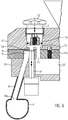
Zum Schließen kann der um eine an der Maschinengehäuseoberseite angebrachte Drehachse schwenkbare Deckel mittels Hebel 26 in die Betriebsposition nach unten verschwenkt werden. In dem Innenraum 27 ist ein exzentrisch angeordneter, in Drehung versetzbarer Rotor 28 vorgesehen. In dem Rotor 28 befinden sich die radial verschiebbaren Flügel 23, die mit der Gehäusewand 24 der Flügelzellenpumpe, dem Boden 25 und dem Deckel 9 und der Außenfläche des Rotors 28 Flügelzellen bilden und im abdichtenden Sinn zusammenwirken. Die Flügelzellenpumpe weist weiter einen Bräteinlass 29 und einen Brätauslass 31. An dem Bräteinlass 29 schließt sich in Drehrichtung A gesehen ein Druckbereich 30 an, in dem sich die Flügelzellen 7 in ihrem Volumen verkleinern. Dieser Druckbereich mündet in den Brätauslass 31, der zu einem nicht dargestellten Auslaufrohr führt. Dem Brätauslass folgt in Drehrichtung A gesehen ein Abdichtbereich 32, in dem die Außenfläche des Rotors 28 in direktem Kontakt mit der Innenwand des Pumpengehäuses kommt.To close the pivotable about a mounted on the machine housing top axis of rotation lid can be pivoted by
An den Abdichtbereich schließt sich der Vakuum- oder Saugbereich 33 an, der bis zum Bräteinlass 29 reicht. In diesem Vakuum- bzw. Saugbereich wird ein Unterdruck erzeugt, der das Einfüllen der pastösen Masse erleichtert und dazu dient, dass der pastösen Masse möglichst viel Luft entzogen werden kann. Zum Evakuieren der Flügelzellen 7 in diesem Vakuumbereich 33 (siehe hierzu auch
Bei dem in
Der Füllstand in dem Sammelbehälter 4 darf nicht so hoch werden, dass die Öffnungen 36a und 36b zu dem Kanal 6 bzw. zu der Leitung 35 zum Luftfilter hin verstopfen, da sonst kein Vakuum mehr in den Flügelzellen 7 erzeugt werden kann. Außerdem darf auch der Kanal 6 nicht stark verschmutzen oder verstopfen, damit sichergestellt werden kann, dass ein ausreichendes Vakuum erzeugt wird. Bislang konnte man die Verschmutzung des Kanals 6 nur sehr schwer inspizieren. Den Füllstand, bzw. den Verschmutzungsgrad des Sammelbehälters 4 konnte man nur inspizieren, indem man das Vakuum an der Maschine abschaltete und die Abdeckklappe des Sammelbehälters am Maschinengehäuse 11 öffnete.The level in the collecting
Gemäß der vorliegenden Erfindung ist nun eine Inspektionsöffnung 5 vorgesehen, die über einen Kanal 6 mit dem Sammelbehälter 4 verbunden ist, zum Inspizieren des Kanals und/oder des Sammelbehälters. Wie durch das Auge in
Es ist besonders vorteilhaft, wenn der Kanal 6 zumindest abschnittsweise aus transparentem Material ausgebildet ist, z. B. als transparenter Schlauch und/oder auch der Sammelbehälter zumindest abschnittsweise aus einem transparenten Material ausgebildet ist, derart, dass Licht von außen durch das Material scheinen kann. Dazu kann mindestens eine Beleuchtung 37, z.B. in Form eines LED Strahlers den Kanal 6 und/oder den Sammelbehälter 4 von außen beleuchten. Werden Kanal 6 und/oder der Sammelbehälter 4 von außen beleuchtet, so können Verunreinigungen besonders gut erfasst und erkannt werden. Ist beispielsweise der Kanal 6 verstopft, so erscheint ein dunkler Fleck. Zusätzlich kann eine Kamera 38 (z.B. in einer Aussparung in einer Position über dem höchsten Füllstand im Sammelbehälter 4) angeordnet sein, um den Innenraum des Sammelbehälters 4 aufzunehmen und beispielsweise auf einem Display, z. B. Display 21, darzustellen. Dies ermöglicht eine zusätzliche Überwachungsmöglichkeit. Die Beleuchtungseinrichtung ist beispielsweise ein LED-Strahler.It is particularly advantageous if the
Bei dem in
Die Evakuierungsöffnung 8 ist hier nicht in der Seitenwandung 24 vorgesehen, sondern im Deckel 9. Von der Evakuierungsöffnung 8 erstreckt sich ein weiterer Kanalabschnitt 14 zur Aussparung 13 und mündet ebenfalls in deren unteren Bereich. Gemäß der vorliegenden Erfindung befindet sich nun die Evakuierungsöffnung 8 im Pumpendeckel 9, d. h., dass nach oben abgesaugt wird bzw. die Flügelzellen nach oben hin entlüftet werden und durch den Pumpendeckel 9 abgesaugt wird. Immer, wenn ein Flügel 23 unter der Evakuierungsöffnung 8 durchfährt, wird die pastöse Masse, falls doch etwas am Pumpendeckel abgelagert wurde, vom Pumpenflügel mitgenommen und die Bohrung somit freigehalten. Das Freihalten der Evakuierungsöffnung 8 am Pumpendeckel ist möglich, weil der Spalt zwischen Pumpenflügel 23 und Pumpendeckel 9 deutlich kleiner ist als der radial Spalt zwischen Pumpenwand und Pumpenflügel bei den Lösungen, bei denen sich die Evakuierungsöffnung 8 im Seitenbereich befindet. Somit wird ein Verstopfen der Evakuierungsbohrung durch mitgeschlepptes Brät wirksam verhindert.The
Der Kanal 6 ist also über die Aussparung 13 und dem Abschnitt 14 mit der Flügelzelle, d. h. der Evakuierungsöffnung 8 verbunden. Wie durch den Pfeil in
Vorteilhafterweise ist die Inspektionsöffnung 5 verschließbar ausgebildet. Die Inspektionsöffnung kann mit Hilfe eines Verschlusselements 12 verschlossen werden, wie insbesondere aus
Wenn der in
In dem Verschlusselement, hier dem Verschlusskolben 12, kann mindestens ein Sensor 17a vorgesehen sein zum Messen des Drucks oder der Temperatur oder des Füllstandes. Ein solcher Sensor bzw. solche Sensoren 17b können zusätzlich oder alternativ auch im Pumpendeckel 9 im Vakuum- oder Saugbereich der Flügelzellenpumpe angeordnet sein. Entsprechende Sensorsignale können der Steuerung 22 der Füllmaschine zugeführt werden und dort zur automatischen Prozessüberwachung und Optimierung ausgewertet und verwendet werden.In the closure element, here the
Ein entsprechender Drucksensor 17a, der einfach zu demontieren und zu reinigen ist, kann die Funktion des Evakuierungssystems zwischen Vakuumpumpe 3 und Verschlusskolben wirksam überwachen. Der Sensor 17b ist in der Lage, die realen Druckverhältnisse im Saugbereich der Flügelzellenpumpe zu überwachen. Beim Einsatz beider Sensor 17a, 17b ist eine detaillierte Aussage über mögliche Fehler (z. B. Verschluss von Vakuumkanälen) im Evakuierungssystem möglich.A
Weicht beispielsweise der vom Sensor 17a gemessene Druck von einem Sollwert ab, so ist dies ebenfalls ein Indiz, dass eine Verunreinigung vorliegt und eine Reinigung notwendig ist.If, for example, the pressure measured by the
Über einen Druckanstieg und eine damit verbundene Veränderung der Position des Stößels kann man dann erkennen, dass gegebenenfalls der Kanal 6 und/oder der Sammelbehälter zu stark verschmutzt sind.By way of an increase in pressure and an associated change in the position of the plunger, it can then be seen that, if appropriate, the
Bei den zuvor gezeigten Ausführungsbeispielen ist vorteilhafterweise die Evakuierungsöffnung 8 im Pumpendeckel 9 integriert. Das Prinzip der freien Einsehbarkeit ist jedoch ebenso realisiert, wenn die Evakuierungsöffnung 8 in einer Seitenwand 24 der Flügelzellenpumpe vorgesehen ist und ein entsprechender Kanalabschnitt 14 der mit der Evakuierungsöffnung verbunden ist, entweder direkt in den Kanal 6 oder aber z. B. in eine Aussparung 13 mündet.In the embodiments shown above, the
Wie aus
Die vorherigen Ausführungsbeispiele in Zusammenhang mit den
Gemäß dem erfindungsgemäßen Verfahren kann wie zuvor beschrieben der Verschmutzungszustand des Sammelbehälters 4 der Füllmaschine, zumindest aber der Kanal 6 inspiziert werden. According to the method according to the invention, as described above, the soiling state of the collecting
Claims (18)
- Filling machine (1) for filling a pasty mass, in particular for the production of sausages with- a vane cell pump (2) for conveying said pasty mass,- a vacuum pump (3) for generating negative pressure in the vane cells (7) of said vane cell pump (2),where said vane cell pump (2) is in communication with said vacuum pump (3) via a collection container (4) for pasty mass that is dragged along, characterized by
an inspection opening (5) which is via a channel (6) in communication with said collection container (4) for inspecting said channel (6) and/or said collection container (4). - Filling machine according to claim 1, characterized in that said channel (6) and/or said collection container (4) can be freely inspected from a position above said upper side (50) of said machine housing (11) through said inspection opening, where said inspection opening (5) is advantageously located in a plane which is inclined by 0° to 45°, in particular 0° to 15° to a horizontal plane.
- Filling machine according to claim 1, characterized in that said channel (6) is in communication with an evacuation opening (8) in said vane cell pump (2).
- Filling machine according to at least one of the claims 1 to 3, characterized in that said inspection opening (8) is disposed in a cover (9) of said vane cell pump (2) or a pivot housing (10) on which said cover (9) is arranged, or in a machine housing (11), such that said channel (6) and/or said collection container (4) can be inspected through said inspection opening (5) when said cover (9) is closed.
- Filling machine according to at least one of the preceding claims, characterized in that there is at least one straight optical path connecting said inspection opening (5) with an inlet (36a) to said collection container, where in particular said channel (6) extends substantially straight, in particular at an angle of 0° to 45°, preferably 0° to 5° to a vertical longitudinal axis of said filling machine (1).
- Filling machine according to at least one of the preceding claims, characterized in that said evacuation opening (8) is located in said cover (9) of said vane cell pump (2).
- Device according to at least one of the claims 1 to 6, characterized in that said inspection opening (5) is closable, in particular with a closure element (12), preferably an axially movable piston (12) and/or said closure element (12) comprises an inspection glass.
- Filling machine according to at least one of the preceding claims, characterized in that said inspection opening (5) is disposed in the upper region of a recess (13), where said channel (6) opens in particular in the lower region into said recess (13) and a further channel section (14) being in communication with said evacuation opening also opens in particular in the lower region (15) into said recess (13).
- Filling machine according to claim 8, characterized in that said axially movable piston (12) is axially movable in said recess (13) and can in a lower position separate said channel (6) from said further channel section (14) and/or
can be removed from said recess (13) and/or
can be moved so far upwardly that said channel (6) and said further channel section (14) can be vented. - Filling machine according to at least one of the preceding claims, characterized in that a driven closure cylinder (16) is provided which separates the vacuum connection between said vacuum pump (3) and said vane cell pump (2).
- Filling machine according to at least claim 7, characterized in that a sensor (17) is integrated into said closure element (12) and/or into said cover (9) of said vane cell pump (2), in particular for measuring the temperature and/or the pressure or the filling level, or an optical sensor which optically detects said channel (6) and/or said collection container and illustrates this on a display.
- Filling machine according to at least one of the preceding claims, characterized in that said channel (6) is formed at least in sections from transparent material.
- Filling machine according to at least one of the preceding claims, characterized in that said collection container (4) is formed at least in sections from transparent material.
- Filling machine according to claim 12 or 13, characterized in that at least one illumination (37, 38) for illuminating said channel (6) and/or said collection container (4) is provided from the outside.
- Filling machine according to at least one of the preceding claims, characterized in that said inspection opening (5) is disposed in said side wall of said vane cell pump (2).
- Method for monitoring the state of fouling of a collection container (4) of a filling machine (1) and/or a channel (6) via which said collection container is in communication with said inspection opening according to at least one of the claims 1 to 15, characterized in that said channel (6) and/or said collection container (6) can be inspected through an inspection opening (5) in particular when said cover of a vane cell pump (2) is closed.
- Method according to claim 16, characterized in that said channel (6) to said collection container (4) is cleaned via said inspection opening (5).
- Filling machine according to at least one of claims 1 to 15, characterized in that said evacuation opening (8) and/or a channel section (14) being in communication with said evacuation opening (8) can be inspected through said inspection opening (5).
Priority Applications (6)
| Application Number | Priority Date | Filing Date | Title |
|---|---|---|---|
| ES15163849.1T ES2688923T3 (en) | 2015-04-16 | 2015-04-16 | Stuffing machine and procedure to monitor the state of dirt in a vacuum system of a stuffing machine |
| PL15163849T PL3081088T3 (en) | 2015-04-16 | 2015-04-16 | Filling machine and method for monitoring the contamination in a vacuum system of a filling machine |
| EP15163849.1A EP3081088B1 (en) | 2015-04-16 | 2015-04-16 | Filling machine and method for monitoring the contamination in a vacuum system of a filling machine |
| JP2016047141A JP6187790B2 (en) | 2015-04-16 | 2016-03-10 | Filler and method for monitoring contamination status in a vacuum system of the filler |
| US15/099,484 US9675087B2 (en) | 2015-04-16 | 2016-04-14 | Filling machine and method for monitoring the state of fouling in a vacuum system of a filling machine |
| CN201610237093.9A CN106035596B (en) | 2015-04-16 | 2016-04-15 | The method for silting state up in bottle placer and vacuum system for monitoring bottle placer |
Applications Claiming Priority (1)
| Application Number | Priority Date | Filing Date | Title |
|---|---|---|---|
| EP15163849.1A EP3081088B1 (en) | 2015-04-16 | 2015-04-16 | Filling machine and method for monitoring the contamination in a vacuum system of a filling machine |
Publications (2)
| Publication Number | Publication Date |
|---|---|
| EP3081088A1 EP3081088A1 (en) | 2016-10-19 |
| EP3081088B1 true EP3081088B1 (en) | 2018-09-12 |
Family
ID=52946399
Family Applications (1)
| Application Number | Title | Priority Date | Filing Date |
|---|---|---|---|
| EP15163849.1A Active EP3081088B1 (en) | 2015-04-16 | 2015-04-16 | Filling machine and method for monitoring the contamination in a vacuum system of a filling machine |
Country Status (6)
| Country | Link |
|---|---|
| US (1) | US9675087B2 (en) |
| EP (1) | EP3081088B1 (en) |
| JP (1) | JP6187790B2 (en) |
| CN (1) | CN106035596B (en) |
| ES (1) | ES2688923T3 (en) |
| PL (1) | PL3081088T3 (en) |
Families Citing this family (5)
| Publication number | Priority date | Publication date | Assignee | Title |
|---|---|---|---|---|
| ES2826474T3 (en) * | 2016-02-15 | 2021-05-18 | Gea Food Solutions Bakel Bv | Car detection and security system |
| EP3329782B1 (en) | 2016-12-05 | 2019-02-13 | Albert Handtmann Maschinenfabrik GmbH & Co. KG | Filling machine and method for filling liquid or paste materials with external collecting container |
| DE102017223715A1 (en) * | 2017-12-22 | 2019-06-27 | Magna Powertrain Bad Homburg GmbH | Gerotor pump and method for producing such |
| CN110771668B (en) * | 2019-11-27 | 2021-05-28 | 福建省龙港食品开发有限公司 | Integration meat intestines processingequipment |
| USD981783S1 (en) * | 2021-02-10 | 2023-03-28 | Hemro Ag | Coffee grinder |
Family Cites Families (20)
| Publication number | Priority date | Publication date | Assignee | Title |
|---|---|---|---|---|
| US3658446A (en) * | 1970-04-13 | 1972-04-25 | Case Co J I | Force compensating means for fluid translating device |
| US3742556A (en) * | 1971-07-02 | 1973-07-03 | Townsend Engineering Co | Meat emulsion pump |
| DE8914705U1 (en) * | 1989-12-14 | 1990-08-30 | Albert Handtmann Maschinenfabrik GmbH & Co KG, 7950 Biberach | Vane pump for conveying pasty masses, especially sausage meat |
| US5129316A (en) * | 1991-01-28 | 1992-07-14 | Alexander Calderon | Combination homogenizer-vacuum loader for meat products |
| JPH05236863A (en) * | 1992-03-02 | 1993-09-17 | Higashimoto Kikai:Kk | Apparatus for vacuum-packing raw material meat |
| DE9420306U1 (en) * | 1994-12-19 | 1995-02-16 | Albert Handtmann Maschinenfabrik GmbH & Co KG, 88400 Biberach | Vane pump |
| GB2317817B (en) * | 1997-01-30 | 1998-12-02 | Notetry Ltd | Vacuum cleaner |
| DE19916582C2 (en) | 1999-04-13 | 2001-04-26 | Handtmann Albert Maschf | Process and vacuum filler for filling a pasty mass |
| DE19925417C1 (en) * | 1999-06-02 | 2000-10-26 | Handtmann Albert Maschf | Vacuum filling method for sausage meat paste has liquid container for excess liquid vented to atmosphere via proportional valve and parallel logic valve |
| CN2600148Y (en) * | 2003-03-07 | 2004-01-21 | 中国进出口商品检验技术研究所 | High-efficient solution degasification device |
| CN1890009A (en) * | 2003-12-03 | 2007-01-03 | 信号系泊浮筒公司 | Gas/liquid separation in water injection into hydrocarbon reservoir |
| CN2667898Y (en) * | 2004-01-08 | 2005-01-05 | 苏州市惠德食品机械工程有限公司 | Vacuum filling pump for meat product |
| ES2307245T3 (en) * | 2006-03-02 | 2008-11-16 | ALBERT HANDTMANN MASCHINENFABRIK GMBH & CO. KG | FILLING MACHINE AND PROCEDURE FOR FEEDING PASTRY MASSES FROM A HOPPER TO A TRANSPORTATION MECHANISM. |
| PL1836896T3 (en) * | 2006-03-09 | 2017-03-31 | Albert Handtmann Maschinenfabrik Gmbh & Co. Kg | Device and method for level control and for controlled evacuation of paste-like masses |
| ES2313478T3 (en) | 2006-03-24 | 2009-03-01 | ALBERT HANDTMANN MASCHINENFABRIK GMBH & CO. KG | CELL PUMP OF PALLETS. |
| PL1997384T3 (en) * | 2007-05-29 | 2009-11-30 | Handtmann Albert Maschf | Temperature regulation of the mass flow in a filling machine |
| ES2427417T3 (en) * | 2011-05-20 | 2013-10-30 | Albert Handtmann Maschinenfabrik Gmbh & Co. Kg | Vacuum regulator in a vacuum filler without outside air supply |
| NL2006958C2 (en) * | 2011-06-17 | 2012-12-18 | Marel Townsend Further Proc Bv | Processing a mass of pumpable foodstuff material. |
| EP2628391B1 (en) * | 2012-02-15 | 2016-04-20 | Albert Handtmann Maschinenfabrik GmbH & Co. KG | Method for filling sausages with paste mass and filling machine for performing this method |
| JP6232625B2 (en) * | 2013-04-26 | 2017-11-22 | ハイテック株式会社 | Filling equipment |
-
2015
- 2015-04-16 PL PL15163849T patent/PL3081088T3/en unknown
- 2015-04-16 ES ES15163849.1T patent/ES2688923T3/en active Active
- 2015-04-16 EP EP15163849.1A patent/EP3081088B1/en active Active
-
2016
- 2016-03-10 JP JP2016047141A patent/JP6187790B2/en active Active
- 2016-04-14 US US15/099,484 patent/US9675087B2/en active Active
- 2016-04-15 CN CN201610237093.9A patent/CN106035596B/en active Active
Non-Patent Citations (1)
| Title |
|---|
| None * |
Also Published As
| Publication number | Publication date |
|---|---|
| JP6187790B2 (en) | 2017-08-30 |
| EP3081088A1 (en) | 2016-10-19 |
| CN106035596A (en) | 2016-10-26 |
| PL3081088T3 (en) | 2019-06-28 |
| ES2688923T3 (en) | 2018-11-07 |
| US20160302431A1 (en) | 2016-10-20 |
| US9675087B2 (en) | 2017-06-13 |
| CN106035596B (en) | 2019-05-03 |
| JP2016202167A (en) | 2016-12-08 |
Similar Documents
| Publication | Publication Date | Title |
|---|---|---|
| EP3081088B1 (en) | Filling machine and method for monitoring the contamination in a vacuum system of a filling machine | |
| DE102008000262B4 (en) | Apparatus and method for filtering microtome cut waste in airflow | |
| DE3239524C2 (en) | Device for feeding fibres to a textile machine | |
| EP3081813B1 (en) | Filling machine and method for filling paste masses | |
| DE2612938A1 (en) | METHOD AND DEVICE FOR MANUFACTURING CHEESE BLOCKS FROM CRUDE CHEESE curd | |
| EP3296075A1 (en) | Feeding apparatus for feeding a viscous material from a container and method for operating the feeding apparatus | |
| DE102012012594B4 (en) | Device for separating solid particles and method for its operation | |
| DE3411918C2 (en) | ||
| DE3835553C1 (en) | Method for automatic emptying and highly selective isolation of different fluids via the head space of a vessel in which the fluids are present in layered formation and apparatus for carrying out the method and for cleaning the vessel | |
| EP2613893B1 (en) | Container-cleaning system and method | |
| DE102014105865B4 (en) | Filling device | |
| EP1644096B1 (en) | Water tank with filter cartridge | |
| DE202016104883U1 (en) | Treatment device for the treatment of liquid and viscous material | |
| DE20201367U1 (en) | Device for separating and removing chips and working fluid | |
| EP2033700A1 (en) | Filter cartridge | |
| DE4343443C2 (en) | Method and device for dosing absorbent substances | |
| DE102013014028A1 (en) | Device for separating suspended matter from air | |
| DE4006558C2 (en) | ||
| DE102019117181B3 (en) | Removal device for liquid containers | |
| DE4020156A1 (en) | Cleaning contaminated broken ground or filling material - involves water storage and circulation system and sealed container mounted on chassis | |
| EP3610179B1 (en) | Device for sealing and evacuating a container containing a paste-like liquid | |
| DE102008004389B4 (en) | loader | |
| EP0953298A1 (en) | Apparatus for feeding tobacco to a rod making machine | |
| DE4420556C2 (en) | Device for removing viscous liquids from a barrel | |
| DE202020106327U1 (en) | Powder container for providing a powder bed |
Legal Events
| Date | Code | Title | Description |
|---|---|---|---|
| PUAI | Public reference made under article 153(3) epc to a published international application that has entered the european phase |
Free format text: ORIGINAL CODE: 0009012 |
|
| 17P | Request for examination filed |
Effective date: 20151120 |
|
| AK | Designated contracting states |
Kind code of ref document: A1 Designated state(s): AL AT BE BG CH CY CZ DE DK EE ES FI FR GB GR HR HU IE IS IT LI LT LU LV MC MK MT NL NO PL PT RO RS SE SI SK SM TR |
|
| AX | Request for extension of the european patent |
Extension state: BA ME |
|
| REG | Reference to a national code |
Ref country code: DE Ref legal event code: R079 Ref document number: 502015005788 Country of ref document: DE Free format text: PREVIOUS MAIN CLASS: A22C0011080000 Ipc: F04C0014000000 |
|
| RIC1 | Information provided on ipc code assigned before grant |
Ipc: F04C 2/344 20060101ALI20180213BHEP Ipc: F04C 13/00 20060101ALI20180213BHEP Ipc: A22C 11/08 20060101ALI20180213BHEP Ipc: A22C 11/06 20060101ALI20180213BHEP Ipc: F04C 14/00 20060101AFI20180213BHEP |
|
| GRAP | Despatch of communication of intention to grant a patent |
Free format text: ORIGINAL CODE: EPIDOSNIGR1 |
|
| STAA | Information on the status of an ep patent application or granted ep patent |
Free format text: STATUS: GRANT OF PATENT IS INTENDED |
|
| INTG | Intention to grant announced |
Effective date: 20180403 |
|
| GRAS | Grant fee paid |
Free format text: ORIGINAL CODE: EPIDOSNIGR3 |
|
| GRAA | (expected) grant |
Free format text: ORIGINAL CODE: 0009210 |
|
| STAA | Information on the status of an ep patent application or granted ep patent |
Free format text: STATUS: THE PATENT HAS BEEN GRANTED |
|
| AK | Designated contracting states |
Kind code of ref document: B1 Designated state(s): AL AT BE BG CH CY CZ DE DK EE ES FI FR GB GR HR HU IE IS IT LI LT LU LV MC MK MT NL NO PL PT RO RS SE SI SK SM TR |
|
| REG | Reference to a national code |
Ref country code: GB Ref legal event code: FG4D Free format text: NOT ENGLISH |
|
| REG | Reference to a national code |
Ref country code: CH Ref legal event code: EP |
|
| REG | Reference to a national code |
Ref country code: IE Ref legal event code: FG4D Free format text: LANGUAGE OF EP DOCUMENT: GERMAN |
|
| REG | Reference to a national code |
Ref country code: DE Ref legal event code: R096 Ref document number: 502015005788 Country of ref document: DE |
|
| REG | Reference to a national code |
Ref country code: AT Ref legal event code: REF Ref document number: 1040919 Country of ref document: AT Kind code of ref document: T Effective date: 20181015 |
|
| REG | Reference to a national code |
Ref country code: ES Ref legal event code: FG2A Ref document number: 2688923 Country of ref document: ES Kind code of ref document: T3 Effective date: 20181107 |
|
| REG | Reference to a national code |
Ref country code: NL Ref legal event code: FP |
|
| REG | Reference to a national code |
Ref country code: LT Ref legal event code: MG4D |
|
| PG25 | Lapsed in a contracting state [announced via postgrant information from national office to epo] |
Ref country code: FI Free format text: LAPSE BECAUSE OF FAILURE TO SUBMIT A TRANSLATION OF THE DESCRIPTION OR TO PAY THE FEE WITHIN THE PRESCRIBED TIME-LIMIT Effective date: 20180912 Ref country code: RS Free format text: LAPSE BECAUSE OF FAILURE TO SUBMIT A TRANSLATION OF THE DESCRIPTION OR TO PAY THE FEE WITHIN THE PRESCRIBED TIME-LIMIT Effective date: 20180912 Ref country code: GR Free format text: LAPSE BECAUSE OF FAILURE TO SUBMIT A TRANSLATION OF THE DESCRIPTION OR TO PAY THE FEE WITHIN THE PRESCRIBED TIME-LIMIT Effective date: 20181213 Ref country code: NO Free format text: LAPSE BECAUSE OF FAILURE TO SUBMIT A TRANSLATION OF THE DESCRIPTION OR TO PAY THE FEE WITHIN THE PRESCRIBED TIME-LIMIT Effective date: 20181212 Ref country code: BG Free format text: LAPSE BECAUSE OF FAILURE TO SUBMIT A TRANSLATION OF THE DESCRIPTION OR TO PAY THE FEE WITHIN THE PRESCRIBED TIME-LIMIT Effective date: 20181212 Ref country code: SE Free format text: LAPSE BECAUSE OF FAILURE TO SUBMIT A TRANSLATION OF THE DESCRIPTION OR TO PAY THE FEE WITHIN THE PRESCRIBED TIME-LIMIT Effective date: 20180912 Ref country code: LT Free format text: LAPSE BECAUSE OF FAILURE TO SUBMIT A TRANSLATION OF THE DESCRIPTION OR TO PAY THE FEE WITHIN THE PRESCRIBED TIME-LIMIT Effective date: 20180912 |
|
| PG25 | Lapsed in a contracting state [announced via postgrant information from national office to epo] |
Ref country code: HR Free format text: LAPSE BECAUSE OF FAILURE TO SUBMIT A TRANSLATION OF THE DESCRIPTION OR TO PAY THE FEE WITHIN THE PRESCRIBED TIME-LIMIT Effective date: 20180912 Ref country code: LV Free format text: LAPSE BECAUSE OF FAILURE TO SUBMIT A TRANSLATION OF THE DESCRIPTION OR TO PAY THE FEE WITHIN THE PRESCRIBED TIME-LIMIT Effective date: 20180912 Ref country code: AL Free format text: LAPSE BECAUSE OF FAILURE TO SUBMIT A TRANSLATION OF THE DESCRIPTION OR TO PAY THE FEE WITHIN THE PRESCRIBED TIME-LIMIT Effective date: 20180912 |
|
| PG25 | Lapsed in a contracting state [announced via postgrant information from national office to epo] |
Ref country code: RO Free format text: LAPSE BECAUSE OF FAILURE TO SUBMIT A TRANSLATION OF THE DESCRIPTION OR TO PAY THE FEE WITHIN THE PRESCRIBED TIME-LIMIT Effective date: 20180912 Ref country code: CZ Free format text: LAPSE BECAUSE OF FAILURE TO SUBMIT A TRANSLATION OF THE DESCRIPTION OR TO PAY THE FEE WITHIN THE PRESCRIBED TIME-LIMIT Effective date: 20180912 Ref country code: IS Free format text: LAPSE BECAUSE OF FAILURE TO SUBMIT A TRANSLATION OF THE DESCRIPTION OR TO PAY THE FEE WITHIN THE PRESCRIBED TIME-LIMIT Effective date: 20190112 Ref country code: EE Free format text: LAPSE BECAUSE OF FAILURE TO SUBMIT A TRANSLATION OF THE DESCRIPTION OR TO PAY THE FEE WITHIN THE PRESCRIBED TIME-LIMIT Effective date: 20180912 |
|
| PG25 | Lapsed in a contracting state [announced via postgrant information from national office to epo] |
Ref country code: SM Free format text: LAPSE BECAUSE OF FAILURE TO SUBMIT A TRANSLATION OF THE DESCRIPTION OR TO PAY THE FEE WITHIN THE PRESCRIBED TIME-LIMIT Effective date: 20180912 Ref country code: SK Free format text: LAPSE BECAUSE OF FAILURE TO SUBMIT A TRANSLATION OF THE DESCRIPTION OR TO PAY THE FEE WITHIN THE PRESCRIBED TIME-LIMIT Effective date: 20180912 Ref country code: PT Free format text: LAPSE BECAUSE OF FAILURE TO SUBMIT A TRANSLATION OF THE DESCRIPTION OR TO PAY THE FEE WITHIN THE PRESCRIBED TIME-LIMIT Effective date: 20190112 |
|
| REG | Reference to a national code |
Ref country code: DE Ref legal event code: R097 Ref document number: 502015005788 Country of ref document: DE |
|
| PLBE | No opposition filed within time limit |
Free format text: ORIGINAL CODE: 0009261 |
|
| STAA | Information on the status of an ep patent application or granted ep patent |
Free format text: STATUS: NO OPPOSITION FILED WITHIN TIME LIMIT |
|
| PG25 | Lapsed in a contracting state [announced via postgrant information from national office to epo] |
Ref country code: DK Free format text: LAPSE BECAUSE OF FAILURE TO SUBMIT A TRANSLATION OF THE DESCRIPTION OR TO PAY THE FEE WITHIN THE PRESCRIBED TIME-LIMIT Effective date: 20180912 |
|
| 26N | No opposition filed |
Effective date: 20190613 |
|
| PG25 | Lapsed in a contracting state [announced via postgrant information from national office to epo] |
Ref country code: SI Free format text: LAPSE BECAUSE OF FAILURE TO SUBMIT A TRANSLATION OF THE DESCRIPTION OR TO PAY THE FEE WITHIN THE PRESCRIBED TIME-LIMIT Effective date: 20180912 |
|
| REG | Reference to a national code |
Ref country code: CH Ref legal event code: PL |
|
| REG | Reference to a national code |
Ref country code: BE Ref legal event code: MM Effective date: 20190430 |
|
| PG25 | Lapsed in a contracting state [announced via postgrant information from national office to epo] |
Ref country code: LU Free format text: LAPSE BECAUSE OF NON-PAYMENT OF DUE FEES Effective date: 20190416 Ref country code: MC Free format text: LAPSE BECAUSE OF FAILURE TO SUBMIT A TRANSLATION OF THE DESCRIPTION OR TO PAY THE FEE WITHIN THE PRESCRIBED TIME-LIMIT Effective date: 20180912 |
|
| PG25 | Lapsed in a contracting state [announced via postgrant information from national office to epo] |
Ref country code: CH Free format text: LAPSE BECAUSE OF NON-PAYMENT OF DUE FEES Effective date: 20190430 Ref country code: LI Free format text: LAPSE BECAUSE OF NON-PAYMENT OF DUE FEES Effective date: 20190430 |
|
| PG25 | Lapsed in a contracting state [announced via postgrant information from national office to epo] |
Ref country code: BE Free format text: LAPSE BECAUSE OF NON-PAYMENT OF DUE FEES Effective date: 20190430 |
|
| PG25 | Lapsed in a contracting state [announced via postgrant information from national office to epo] |
Ref country code: TR Free format text: LAPSE BECAUSE OF FAILURE TO SUBMIT A TRANSLATION OF THE DESCRIPTION OR TO PAY THE FEE WITHIN THE PRESCRIBED TIME-LIMIT Effective date: 20180912 |
|
| PG25 | Lapsed in a contracting state [announced via postgrant information from national office to epo] |
Ref country code: IE Free format text: LAPSE BECAUSE OF NON-PAYMENT OF DUE FEES Effective date: 20190416 |
|
| PG25 | Lapsed in a contracting state [announced via postgrant information from national office to epo] |
Ref country code: CY Free format text: LAPSE BECAUSE OF FAILURE TO SUBMIT A TRANSLATION OF THE DESCRIPTION OR TO PAY THE FEE WITHIN THE PRESCRIBED TIME-LIMIT Effective date: 20180912 |
|
| PG25 | Lapsed in a contracting state [announced via postgrant information from national office to epo] |
Ref country code: MT Free format text: LAPSE BECAUSE OF FAILURE TO SUBMIT A TRANSLATION OF THE DESCRIPTION OR TO PAY THE FEE WITHIN THE PRESCRIBED TIME-LIMIT Effective date: 20180912 Ref country code: HU Free format text: LAPSE BECAUSE OF FAILURE TO SUBMIT A TRANSLATION OF THE DESCRIPTION OR TO PAY THE FEE WITHIN THE PRESCRIBED TIME-LIMIT; INVALID AB INITIO Effective date: 20150416 |
|
| PG25 | Lapsed in a contracting state [announced via postgrant information from national office to epo] |
Ref country code: MK Free format text: LAPSE BECAUSE OF FAILURE TO SUBMIT A TRANSLATION OF THE DESCRIPTION OR TO PAY THE FEE WITHIN THE PRESCRIBED TIME-LIMIT Effective date: 20180912 |
|
| P01 | Opt-out of the competence of the unified patent court (upc) registered |
Effective date: 20230523 |
|
| PGFP | Annual fee paid to national office [announced via postgrant information from national office to epo] |
Ref country code: NL Payment date: 20240425 Year of fee payment: 10 |
|
| PGFP | Annual fee paid to national office [announced via postgrant information from national office to epo] |
Ref country code: PL Payment date: 20240325 Year of fee payment: 10 |
|
| PGFP | Annual fee paid to national office [announced via postgrant information from national office to epo] |
Ref country code: GB Payment date: 20240423 Year of fee payment: 10 |
|
| PGFP | Annual fee paid to national office [announced via postgrant information from national office to epo] |
Ref country code: DE Payment date: 20240425 Year of fee payment: 10 |
|
| PGFP | Annual fee paid to national office [announced via postgrant information from national office to epo] |
Ref country code: ES Payment date: 20240503 Year of fee payment: 10 |
|
| PGFP | Annual fee paid to national office [announced via postgrant information from national office to epo] |
Ref country code: AT Payment date: 20240423 Year of fee payment: 10 |
|
| PGFP | Annual fee paid to national office [announced via postgrant information from national office to epo] |
Ref country code: IT Payment date: 20240426 Year of fee payment: 10 Ref country code: FR Payment date: 20240423 Year of fee payment: 10 |