EP3081068A1 - Tondeuse à gazon autonome, module pour une tondeuse à gazon autonome et système comprenant une telle tondeuse à gazon autonome et un tel module - Google Patents
Tondeuse à gazon autonome, module pour une tondeuse à gazon autonome et système comprenant une telle tondeuse à gazon autonome et un tel module Download PDFInfo
- Publication number
- EP3081068A1 EP3081068A1 EP15001128.6A EP15001128A EP3081068A1 EP 3081068 A1 EP3081068 A1 EP 3081068A1 EP 15001128 A EP15001128 A EP 15001128A EP 3081068 A1 EP3081068 A1 EP 3081068A1
- Authority
- EP
- European Patent Office
- Prior art keywords
- lawn mower
- autonomous lawn
- module
- electrical connection
- connection means
- Prior art date
- Legal status (The legal status is an assumption and is not a legal conclusion. Google has not performed a legal analysis and makes no representation as to the accuracy of the status listed.)
- Granted
Links
- 230000007274 generation of a signal involved in cell-cell signaling Effects 0.000 claims abstract description 10
- 238000004891 communication Methods 0.000 claims description 23
- 238000012545 processing Methods 0.000 claims description 14
- 230000000007 visual effect Effects 0.000 claims description 11
- 238000001514 detection method Methods 0.000 claims description 8
- 244000025254 Cannabis sativa Species 0.000 claims description 7
- 238000003860 storage Methods 0.000 claims description 5
- 230000036541 health Effects 0.000 claims description 2
- 230000006870 function Effects 0.000 description 25
- 238000000034 method Methods 0.000 description 5
- 230000033001 locomotion Effects 0.000 description 4
- 230000008859 change Effects 0.000 description 3
- 230000008569 process Effects 0.000 description 3
- 230000006978 adaptation Effects 0.000 description 2
- 230000008901 benefit Effects 0.000 description 2
- 238000005520 cutting process Methods 0.000 description 2
- 238000013461 design Methods 0.000 description 2
- 238000011161 development Methods 0.000 description 2
- 230000018109 developmental process Effects 0.000 description 2
- 230000005226 mechanical processes and functions Effects 0.000 description 2
- 230000008447 perception Effects 0.000 description 2
- 230000001960 triggered effect Effects 0.000 description 2
- 230000003247 decreasing effect Effects 0.000 description 1
- 230000001419 dependent effect Effects 0.000 description 1
- 230000003993 interaction Effects 0.000 description 1
- 238000004519 manufacturing process Methods 0.000 description 1
- 238000010295 mobile communication Methods 0.000 description 1
- 230000003252 repetitive effect Effects 0.000 description 1
Images
Classifications
-
- A—HUMAN NECESSITIES
- A01—AGRICULTURE; FORESTRY; ANIMAL HUSBANDRY; HUNTING; TRAPPING; FISHING
- A01D—HARVESTING; MOWING
- A01D34/00—Mowers; Mowing apparatus of harvesters
- A01D34/006—Control or measuring arrangements
- A01D34/008—Control or measuring arrangements for automated or remotely controlled operation
Definitions
- the invention relates to the field of autonomous lawn mowers.
- Autonomous lawn mowers are an increasing field. A few years ago autonomous lawn mowers have been presented and since then the capability of autonomous lawn mowers to detect obstacles and to fulfill their mowing task without interaction of a user have been improved. Of course the expectations of the customer also increased since then. Thus, autonomous lawn mowers with more sophisticated functions have been developed. But one problem is that the more sophisticated lawn mowers are quite expensive, because the included functionality necessarily needs higher effort in development and also production of such lawn mowers require more expensive parts. Thus, many potential customers will refrain from buying such sophisticated lawn mowers and rather buy a conventional lawn mower or at least a simpler autonomous lawn mower.
- EP 2 286 653 A2 An example for a more sophisticated lawn mower is disclosed in EP 2 286 653 A2 .
- This autonomous lawn mower is equipped with a camera and combines grass recognition with the output of a grass sensor. Due to capturing images of the environment more sophisticated or intelligent functions for controlling the autonomous lawn mower can be implemented. But the camera or the grass sensor are integrated in the autonomous lawn mower itself again and thus the customer has to decide before buying the lawn mower if he wants such functionality or whether he is satisfied with a cheaper one that then has no capability of upgrading the functionality of his mower.
- module for such autonomous lawn mower and a system consisting of the autonomous lawn mower and the module that enable a customer to decide later on whether a change of the module shall be performed so that additional features and functions can be added to the lawn mower by the new module.
- module means any part that is intended to be replaced by another part, thereby making use of the same mechanical interface of the autonomous lawn mower.
- the autonomous lawn mower of the present invention comprises a control unit that is in electrical connection with electrical connection means. Additionally there is at least one replaceable part forming a module.
- the electrical connection means are located such that connection and disconnection of the electrical connection means and its counterpart of the replaceable part and another replaceable part respectively can be easily performed when replacing the replaceable part. Easy in this regard means that no further disassembly of the lawn mower except for detachment of the replaceable part is necessary.
- the disconnection is performed either automatically by detaching the replaceable part, e.g.
- module including a camera unit is configured to replace the initially used replaceable part and serves the same purpose as the replaced part but in addition further functions such as image capturing or the like.
- the camera is used as a preferred example for explaining the addition of functionality, but of course any device or means that adds or adapts functionality can be used.
- the electrical connection means is located such that connection and disconnection of the electrical connection means and its counterpart of the replaceable part can be performed when replacing the replaceable part it is easy to remove the old replaceable part and substitute it with a new one. No further assembly and disassembly is necessary and in particular such replacement then can be performed by the customer and user of the autonomous lawn mower himself. Since replacement is quite simple and an electrical connection means dedicated for connecting a replaceable part, e.g. a new camera module, new developments regarding camera technique or even the processing of images captured by the camera can be added to the autonomous lawn mower later on. This results in a basic configuration that can be purchased by a customer not limiting the functionality for the future.
- a basic configuration may be limited to controlling the driving of the autonomous lawn mower by bump sensors and border wire and without more sophisticated control to avoid obstacles as it is possible on the basis of image processing for obstacle detection and the like. If a costumer later on wants to improve the functionality of his autonomous lawn mower it is then possible to replace the initially used replaceable part by a new replaceable part that then includes for example a camera and maybe also an image processing unit can thus deliver signals to the control unit of the autonomous lawn mower which is already prepared to control the autonomous lawn mower on the basis of these signals. But since the camera unit is not provided initially the basic configuration of the autonomous lawn mower is cheaper. Thus, it is possible that the customer buys the basic configuration and later on if he is willing to spend further money for his comfort he can add such more sophisticated functions.
- a module according to the invention that may substitute a previously used module or even the initially used module comprises a signal generation unit and a counterpart for the electrical connection means of the lawn mower.
- the module (rather its signal generation unit) an electrical signal can be transmitted to the control unit of the autonomous lawn mower which is then used to control driving of the autonomous lawn mower.
- the electrical connection means can be a connector that is attached to a harness of the autonomous lawn mower and that can be connected to a connector on the module's side.
- the connector may be connected to a harness of the module.
- the electrical connection means is fixedly attached to the autonomous lawn mower (any rigid part thereof) and the counterpart is correspondingly and fixedly attached to the module without the use of a flexible harness so that the module can simply be inserted for example into a socket as electrical connection means.
- the module is configured in such a way that it fulfills not only the requirements of the newly added function but also the function of the replaced part. That means in case that the replaceable part that was initially used is for example a part of a cover of the autonomous lawn mower, the autonomous lawn mower's module is designed in such a way that the cover function will also be present after replacing the replaceable part. In case of the old replaceable part being a cover this means that the replacing module has to cover the recess that is the result of detachment of the old replaceable part. This is achieve by designing the mechanical interface of all modules dedicated for a particular replacement of one type of lawn mower in the same way.
- control unit is configured to control a drive unit of the autonomous lawn mower on the basis of signals receivable via the electrical connection means.
- the autonomous lawn mower can provide the self-propelling function on the basis of, for example, simple obstacle detection and/or borderline detection and random drive. This could be achieved by using the commonly known borderline technique as mentioned above with respect to the state of the art and additionally provide bump sensors in order to change the driving direction after contact with an obstacle.
- the replaceable part is replaced by a new replaceable part being a module according to the invention which is connected by its counterpart and the electrical connection means and which transmits electrical signals to the control unit of the autonomous lawn mower these signals are taken into consideration and information contained therein is used for controlling the drive unit of the autonomous lawn mower.
- the module comprises a camera and that image signals are transferred to the control unit. In that case the processing of the image signals is performed in the control unit of the autonomous lawn mower.
- the information from images captured by image capturing means is processed in the module itself and thus signals are generated by the module itself that allow assisting control of the autonomous lawn mower on the basis of images captured by the camera, for example.
- signals can include information about a position and size of an obstacle relative to the lawn mower or even instructions to change the direction for driving.
- the electrical connection means comprises a power connector and/or a communication connector.
- Such communication connector even more preferably is a CAN bus connector.
- Using such standardized bus connection has the advantage that it is easier to develop a plurality of different modules that all use the same communication protocol. By doing so it is possible to provide a greater variability of the autonomous lawn mower by offering a plurality of modules that can be used as replaceable parts that offer different functionality without the need for an adaptation on the mower side.
- the replaceable part is configured to form a service lid.
- a service lid is present in most cases in some form anyway and thus the design of the autonomous lawn mower does not need to be changed to a large extent. It is then possible to still maintain the function of a service lid by the module, but because of the connection by means of the electrical connection means additional functions can be provided by the replacing replaceable part, i.e. the module according to the invention.
- the service lid for example covers a height adjustment means or adjusting the cutting height of the autonomous lawn mower or provides access to a control panel dedicated for programming the lawn mower.
- the control unit is updatable via the electrical connection means.
- the update function is triggered by just connecting the module to the autonomous lawn mower.
- a storage comprised in the module on which software for the control unit of the autonomous lawn mower is stored. After attaching the module to the autonomous lawn mower, the update will be performed automatically.
- the autonomous lawn mower comprises a plurality of replaceable parts and respective electrical connections over which connected modules can communicate with each other.
- This can even comprise different environment perception modules such as a camera module and additionally a laser sensor module, information of which is used all together in order to generate control signals for the control unit.
- this could be performed by using a processing unit of one of the modules in order to process the information of the different perception modules or the modules can be configured to provide only information about the captured images by, for example, the camera and a laser sensor to the control unit of the autonomous lawn mower where then a processing of the information is performed.
- a separate module is used that provides communication functionality and that can receive and transmit the captured images or the image stream via the respective connection means.
- the module as a replaceable part can comprise only such wireless module as indicated above already so that such module is dedicated for improving the functionality of an autonomous lawn mower that is already equipped with visual obstacle detection or the like, but not yet configured to communicate wirelessly with a distant mobile device, for example, a mobile phone, tablet and the like.
- the wireless communication does not necessarily need to be performed between the autonomous lawn mower equipped with such module and a mobile communication device, but also any other device that is capable of performing wireless communication.
- Preferred examples for such wireless communication are W-LAN, Bluetooth or NFC.
- Preferred examples of the functions that are performed by the data processing unit of the module are visual obstacle functions, visual odometry functions, visual border recognition functions, visual intruder detection functions or visual grass health analysis.
- the functions themselves are already known in the art, but up to now as mentioned above, they are fully integrated in the entire system and no updating of hardware and no addition of such functions is possible yet.
- such additional functionality is included at least partly in the module which as a replaceable part can replace an old replaceable part of the autonomous lawn mower and thereby add such function or use an updated version of such function.
- the system according to the invention comprises an autonomous lawn mower according to one of the aspects mentioned above and a module according to one of the aspects mentioned above with respect to the module.
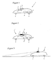
- FIG 1 there is shown an autonomous lawn mower at it is known from the prior art.
- the autonomous lawn mower 1 shown there has a basic configuration.
- the autonomous lawn mower 1 comprises a plurality of wheels 2 on which the autonomous lawn mower moves.
- Height adjustment can be performed by a lever 3 that is accessible through a service lid 4. Since this is well known, the mechanical structure of the height adjustment is not shown in the drawing.
- the service lid 4 can be designed to be fully detached every time the lever 3 is to be operated or, as it is shown in dashed lines in figure 1 , can be connected to the housing or main cover of the autonomous lawn mower 1 by use hinges provided on one side of the lid.
- the autonomous lawn mower 1 is self-propelled. Driving of the autonomous lawn mower 1 is controlled by a control unit 5 that generates driving signals that are supplied to a driving unit 6 which is shown in the figures only very simplified. But the drive unit 6 and the control thereof as such are already well known and such known systems may be used here.
- the conventional system with autonomous lawn mower 1 as shown in figure 1 uses for example a border wire to detect the borders of an area where a lawn shall be mowed and in addition bump sensors (not shown in the drawing) for obstacles that lie within the area the border of which is indicated by the border wire.
- the control unit 5 controls the speed and direction of the autonomous lawn mower 1 by providing the drive unit 6 with drive signals including speed and steering information.
- the service lid 4 is configured to form a replaceable part and thus one, very simple module that has no electronic parts to be connected.
- the replaceable part which does not necessarily need to be the service lid 4 but any module that is currently attached to the lawn mower, can be fully detached from the autonomous lawn mower and replaced by another replaceable part which is described as another module according to the invention. It is to be noted that this new replaceable part which substitutes after detaching the original replaceable part this previous replaceable has the same mechanical functionality as the substituted replaceable part.
- the replaceable part is for example the service lid 4 according to the figure 1
- the new replaceable part which is attached to the autonomous lawn mower 1 thus forms part of the housing or the cover of the autonomous lawn mower 1.
- this new module which is the new replaceable part has additionally functionality. Using such modules increases the functional flexibility of the autonomous lawn 1 mower but avoids that the customer has to buy an autonomous lawn mower with all such functionality right away and thus the costs for the basic configuration can be decreased.
- the customer can buy for example at the beginning of the grass season a lawn mower with a basic configuration and later on add functionality by buying a module for such increased functionality.
- a benefit for the manufacturer is that the sales season is increased because the replaceable parts can be upgrade parts that are bought later.
- the present invention provides a modular concept for autonomous lawn mowers.
- Figure 2 shows the overall configuration of such modular autonomous lawn mower 1'. Same parts as of the commonly known autonomous lawn mower 1 as described in figure 1 are denoted with the same reference numerals and repetitive description thereof is omitted.
- Figure 2 shows the lawn mower 1' according to the present invention where the initially provided service lid 2 is already replaced by a replaceable part which is in the illustrated embodiment a camera module 7. As it is indicated by the dashed lines in figure 2 and as it has already been explained above the basic mechanical function of the replaced service lid 4 is maintained by the module 7.
- the camera module 7 in the present case may be attached to the housing of the autonomous lawn mower 1' by means of hinges so that the camera module 7 can be swung aside and the lever 3 for adjusting the cutting height is still accessible.
- electrical connecting means 8 which in the simplified illustration comprises a power connector as well as a communication connector.
- communication connector can for example be a CAN bus connector.
- the electrical connecting means 8 which is provided by the autonomous lawn mower 1' may consist of a plug that is attached to the end of a harness which is connected also to the control unit 5. Such plug can either be fixedly attached to the housing of the autonomous lawn mower 1' or at least be positioned in a region that is reachable after the service lid 2 has been detached.
- the electrical connecting means 8 is reachable so that the new replaceable part that substitutes the old one may electrically be connected to the autonomous lawn mower 1'.
- the electrical connecting means 8 There are several possibilities to fulfill this requirement. One has already been mentioned and is a connector that is connected to a harness. Another possibility is that there is a socket on the autonomous lawn mower's side and the corresponding module 7 has a plug that can be inserted into the socket. In any case it has to be ensured that the original mechanical functionality of the originally used service lid 2 can still be fulfilled.
- the electrical connecting means 8 meaning the socket, plug or connector is provided so as to be reachable on the outside of the housing of the autonomous lawn mower but of course it is preferable that the electrical connecting means 8 is covered by the housing of the autonomous lawn mower 1' and thus is arranged inside the autonomous lawn mower 1' close to the opening which is covered by the service lid 2.
- the module 7 of course has a counterpart 9 to the electrical connecting means 8, in the easiest case a plug that fits into the socket.
- a plug that fits into the socket.
- Such plug preferably is attached to the end of a module harness 10 which is long enough that opening of the housing of the autonomous lawn mower 1' can still be performed as shown on the right side of Fig. 2 in order to access the lever 3 for height adjustment.
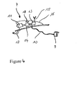
- the module 7 as shown enlarged in Fig. 4 preferably comprises a camera 11.
- the camera 11 captures images of the environment of the autonomous lawn mower 1' and preferably the camera 11 even comprises an image processing unit 14 that directly processes the images captured in order to generate a signal that is used by the control unit 5' for generating the drive signal.
- Power is supplied to the module 7 by the electrical connection means 8 that also is capable of transferring the signals that are generated by a signal generation unit of the module 7 to the control unit 5'.
- the control unit 5' then finally generates the drive signals that are supplied to the drive unit 6.
- the signal generation unit in the embodiment comprises at least the camera 11 and a data processing unit 14, preferably also a wireless communication module 13 and a storage 18.
- software (and/or parameters) for updating software (and/or parameters) that is run in the control unit 5' is stored.
- a software (and/or parameter) update can be performed.
- the update may either start automatically after the connection is established or can be triggered by a user.
- the module 7 is designed so that it integrates smoothly in the overall design of the autonomous lawn mower 1' whereby it particularly fulfills also the mechanical function of the replaced module.
- a housing 16 is fixed to a base plate.
- the base plate is attached to teh autonomous lawn mower 1' by hinges 17 that enable a pivotal movement of the entire module 7 thereby allowing the same access to the inside as the lid 2.
- the connection of the signal generation unit is realized in the illustrated embodiment by a cable or harness 10 one side of which is connected to the processing unit 14. At the other end the counterpart 9 is attached to the cable or harness 10.
- the length of the cable or harness 10 is chosen so that the pivotal movement of the module 7 is not limited and that operation of elements covered by the module 7 in the closed state, like the lever 3 is possible
- the position of a camera 11 included in module 7 provides a good viewing angle as shown in Fig. 3 .
- remote controlling of the autonomous lawn mower 1' by a user or obstacle detection is easily possible.
- the module 7 in addition to the camera 11 comprises said wireless communication unit 13 that can for example directly transmit the images captured by the camera to a remote device like, for example, a cell phone or a tablet or any other device that is also capable of wireless communication.
- the wireless communication unit 13 is connected to an antenna 15 that may be arranged inside housing 16 of the module7 as well.
- Wireless communication could be near field communication (NFC), Bluetooth or in case that larger distances shall be also possible, wireless LAN.
Landscapes
- Life Sciences & Earth Sciences (AREA)
- Environmental Sciences (AREA)
- Harvester Elements (AREA)
- Length Measuring Devices By Optical Means (AREA)
- Control Of Position, Course, Altitude, Or Attitude Of Moving Bodies (AREA)
Priority Applications (3)
| Application Number | Priority Date | Filing Date | Title |
|---|---|---|---|
| EP15001128.6A EP3081068B1 (fr) | 2015-04-17 | 2015-04-17 | Tondeuse à gazon autonome, module pour une tondeuse à gazon autonome et système comprenant une telle tondeuse à gazon autonome et un tel module |
| JP2016029544A JP6704750B2 (ja) | 2015-04-17 | 2016-02-19 | 自律型芝刈機およびそのための置換可能なモジュール |
| US15/079,115 US9848529B2 (en) | 2015-04-17 | 2016-03-24 | Autonomous lawn mower, module for an autonomous lawn mower and system comprising such autonomous lawn mower and module |
Applications Claiming Priority (1)
| Application Number | Priority Date | Filing Date | Title |
|---|---|---|---|
| EP15001128.6A EP3081068B1 (fr) | 2015-04-17 | 2015-04-17 | Tondeuse à gazon autonome, module pour une tondeuse à gazon autonome et système comprenant une telle tondeuse à gazon autonome et un tel module |
Publications (2)
| Publication Number | Publication Date |
|---|---|
| EP3081068A1 true EP3081068A1 (fr) | 2016-10-19 |
| EP3081068B1 EP3081068B1 (fr) | 2021-06-09 |
Family
ID=52987816
Family Applications (1)
| Application Number | Title | Priority Date | Filing Date |
|---|---|---|---|
| EP15001128.6A Active EP3081068B1 (fr) | 2015-04-17 | 2015-04-17 | Tondeuse à gazon autonome, module pour une tondeuse à gazon autonome et système comprenant une telle tondeuse à gazon autonome et un tel module |
Country Status (3)
| Country | Link |
|---|---|
| US (1) | US9848529B2 (fr) |
| EP (1) | EP3081068B1 (fr) |
| JP (1) | JP6704750B2 (fr) |
Cited By (5)
| Publication number | Priority date | Publication date | Assignee | Title |
|---|---|---|---|---|
| IT201600129749A1 (it) * | 2016-12-22 | 2018-06-22 | Dalesio Antonio | Kit di modifica per tagliaerba |
| WO2019238273A1 (fr) * | 2018-06-13 | 2019-12-19 | Positec Power Tools (Suzhou) Co., Ltd. | Dispositif automoteur, module fonctionnel et système de fonctionnement automatique |
| WO2021139402A1 (fr) * | 2020-01-09 | 2021-07-15 | 苏州宝时得电动工具有限公司 | Dispositif de coupe d'herbe intelligent |
| EP3854196A4 (fr) * | 2018-10-31 | 2021-10-13 | Honda Motor Co., Ltd. | Machine de travail autonome |
| WO2024001150A1 (fr) * | 2022-07-01 | 2024-01-04 | 洛阳拖拉机研究所有限公司 | Système de commande électrique basé sur un bus can pour tondeuse électrique |
Families Citing this family (11)
| Publication number | Priority date | Publication date | Assignee | Title |
|---|---|---|---|---|
| JP6635909B2 (ja) * | 2016-12-28 | 2020-01-29 | 本田技研工業株式会社 | 作業機、制御装置及び制御用プログラム |
| WO2018142483A1 (fr) | 2017-01-31 | 2018-08-09 | 本田技研工業株式会社 | Système de travail sans intervention humaine, serveur de gestion et machine de travail sans intervention humaine |
| US11145143B2 (en) | 2017-01-31 | 2021-10-12 | Honda Motor Co., Ltd. | Unmanned work system, management server, and unmanned work machine |
| CN108427409A (zh) * | 2017-02-15 | 2018-08-21 | 苏州宝时得电动工具有限公司 | 自动工作系统,自移动设备及其控制方法 |
| US10869426B2 (en) * | 2017-11-27 | 2020-12-22 | Lely Patent N.V. | Mowing device |
| US10561063B2 (en) * | 2018-01-10 | 2020-02-18 | Honda Motor Co., Ltd. | Autonomous lawnmower using laser scanner |
| EP3779629B1 (fr) | 2018-03-30 | 2022-10-12 | Honda Motor Co., Ltd. | Machine de travail à déplacement autonome et système de commande |
| US20220000017A1 (en) * | 2018-11-20 | 2022-01-06 | Honda Motor Co., Ltd. | Control apparatus of autonomously navigating work machine |
| US11951977B1 (en) | 2019-09-23 | 2024-04-09 | Renu Robotics Corp. | Autonomous vehicle panel and post detection |
| JP7461507B2 (ja) * | 2020-05-08 | 2024-04-03 | フスクバルナ アクティエボラーグ | 包囲空間を上部空間と切断空間とに分割する分割板を備えた芝刈機 |
| CN114145125B (zh) * | 2021-10-15 | 2023-08-08 | 湖南省农业装备研究所 | 一种自锁式自调电动割草机 |
Citations (10)
| Publication number | Priority date | Publication date | Assignee | Title |
|---|---|---|---|---|
| US3570227A (en) | 1969-01-16 | 1971-03-16 | Mowbot Inc | Self-propelled random motion lawnmower |
| US3698523A (en) * | 1969-10-20 | 1972-10-17 | Mowbot Inc | Self-propelled random motion lawnmower |
| WO1990004324A1 (fr) * | 1986-02-04 | 1990-05-03 | Technical Solutions, Inc. | Procede de guidage d'une tondeuse a gazon robotisee |
| US20030144774A1 (en) * | 2002-01-29 | 2003-07-31 | Trissel Ronald L. | Kit and method for converting conventional lawnmower to a robotic lawnmower |
| DE10327223A1 (de) | 2003-06-17 | 2005-01-05 | Gunter Arnold | Selbstfahrender Rasenmäher mit Grasdetektor |
| US20060059880A1 (en) * | 2004-09-13 | 2006-03-23 | Angott Paul G | Unmanned utility vehicle |
| EP2286653A2 (fr) | 2009-08-17 | 2011-02-23 | Robert Bosch GmbH | Plateforme mobile autonome destinée au traitement de surface |
| EP2412219A1 (fr) * | 2010-07-28 | 2012-02-01 | Deere & Company | Boîtier de tondeuse mécanique et tondeuse mécanique |
| WO2013125991A1 (fr) * | 2012-02-22 | 2013-08-29 | Husqvarna Ab | Tondeuse à gazon robotisée |
| US20140121881A1 (en) * | 2012-10-23 | 2014-05-01 | Daniel A. DIAZDELCASTILLO | Autonomous and remote control all purpose machine (arcapm) |
Family Cites Families (3)
| Publication number | Priority date | Publication date | Assignee | Title |
|---|---|---|---|---|
| US8295979B2 (en) * | 2010-01-06 | 2012-10-23 | Deere & Company | Adaptive scheduling of a service robot |
| JP6066487B2 (ja) * | 2013-07-26 | 2017-01-25 | ヤンマー株式会社 | 電動作業車両 |
| EP2884364B1 (fr) * | 2013-12-12 | 2018-09-26 | Hexagon Technology Center GmbH | Véhicule autonome de jardinage équipé d'une caméra |
-
2015
- 2015-04-17 EP EP15001128.6A patent/EP3081068B1/fr active Active
-
2016
- 2016-02-19 JP JP2016029544A patent/JP6704750B2/ja active Active
- 2016-03-24 US US15/079,115 patent/US9848529B2/en active Active
Patent Citations (10)
| Publication number | Priority date | Publication date | Assignee | Title |
|---|---|---|---|---|
| US3570227A (en) | 1969-01-16 | 1971-03-16 | Mowbot Inc | Self-propelled random motion lawnmower |
| US3698523A (en) * | 1969-10-20 | 1972-10-17 | Mowbot Inc | Self-propelled random motion lawnmower |
| WO1990004324A1 (fr) * | 1986-02-04 | 1990-05-03 | Technical Solutions, Inc. | Procede de guidage d'une tondeuse a gazon robotisee |
| US20030144774A1 (en) * | 2002-01-29 | 2003-07-31 | Trissel Ronald L. | Kit and method for converting conventional lawnmower to a robotic lawnmower |
| DE10327223A1 (de) | 2003-06-17 | 2005-01-05 | Gunter Arnold | Selbstfahrender Rasenmäher mit Grasdetektor |
| US20060059880A1 (en) * | 2004-09-13 | 2006-03-23 | Angott Paul G | Unmanned utility vehicle |
| EP2286653A2 (fr) | 2009-08-17 | 2011-02-23 | Robert Bosch GmbH | Plateforme mobile autonome destinée au traitement de surface |
| EP2412219A1 (fr) * | 2010-07-28 | 2012-02-01 | Deere & Company | Boîtier de tondeuse mécanique et tondeuse mécanique |
| WO2013125991A1 (fr) * | 2012-02-22 | 2013-08-29 | Husqvarna Ab | Tondeuse à gazon robotisée |
| US20140121881A1 (en) * | 2012-10-23 | 2014-05-01 | Daniel A. DIAZDELCASTILLO | Autonomous and remote control all purpose machine (arcapm) |
Cited By (9)
| Publication number | Priority date | Publication date | Assignee | Title |
|---|---|---|---|---|
| IT201600129749A1 (it) * | 2016-12-22 | 2018-06-22 | Dalesio Antonio | Kit di modifica per tagliaerba |
| WO2019238273A1 (fr) * | 2018-06-13 | 2019-12-19 | Positec Power Tools (Suzhou) Co., Ltd. | Dispositif automoteur, module fonctionnel et système de fonctionnement automatique |
| CN112165856A (zh) * | 2018-06-13 | 2021-01-01 | 苏州宝时得电动工具有限公司 | 自移动设备、功能模块以及自动工作系统 |
| CN112165856B (zh) * | 2018-06-13 | 2023-09-12 | 苏州宝时得电动工具有限公司 | 自移动设备、功能模块以及自动工作系统 |
| US11782445B2 (en) | 2018-06-13 | 2023-10-10 | Positec Power Tools (Suzhou) Co., Ltd. | Self-moving device, functional module, and automatic working system |
| EP4324320A3 (fr) * | 2018-06-13 | 2024-05-15 | Positec Power Tools (Suzhou) Co., Ltd. | Dispositif automoteur et système de fonctionnement automatique |
| EP3854196A4 (fr) * | 2018-10-31 | 2021-10-13 | Honda Motor Co., Ltd. | Machine de travail autonome |
| WO2021139402A1 (fr) * | 2020-01-09 | 2021-07-15 | 苏州宝时得电动工具有限公司 | Dispositif de coupe d'herbe intelligent |
| WO2024001150A1 (fr) * | 2022-07-01 | 2024-01-04 | 洛阳拖拉机研究所有限公司 | Système de commande électrique basé sur un bus can pour tondeuse électrique |
Also Published As
| Publication number | Publication date |
|---|---|
| US9848529B2 (en) | 2017-12-26 |
| US20160302354A1 (en) | 2016-10-20 |
| EP3081068B1 (fr) | 2021-06-09 |
| JP6704750B2 (ja) | 2020-06-03 |
| JP2016202165A (ja) | 2016-12-08 |
Similar Documents
| Publication | Publication Date | Title |
|---|---|---|
| US9848529B2 (en) | Autonomous lawn mower, module for an autonomous lawn mower and system comprising such autonomous lawn mower and module | |
| EP1679030B1 (fr) | Système d'imagerie vidéo endoscopique avec fonction de mise à jour | |
| US20200351446A1 (en) | Terminal equipped with removable robotic module | |
| US9357902B2 (en) | Updateable endoscopic video imaging system with unified electro-optic cable | |
| EP2870853A1 (fr) | Tondeuse à gazon avec commande à distance | |
| US10349794B2 (en) | Autonomous traveling body | |
| US20160330363A1 (en) | Positioning Apparatus for Photographic and Video Imaging and Recording and System Utilizing the Same | |
| US11782445B2 (en) | Self-moving device, functional module, and automatic working system | |
| US20140135062A1 (en) | Positioning apparatus for photographic and video imaging and recording and system utilizing same | |
| EP3939407A1 (fr) | Système et procédé de synchronisation de déchargement de grain assisté ou automatique | |
| US20170230565A1 (en) | Automatic follow focus system | |
| CN210927825U (zh) | 一种无人机控制系统 | |
| KR101343398B1 (ko) | 모션캡처 기반의 휴머노이드 시스템 | |
| US20230079038A1 (en) | Method And System For A Trail Camera With Modular Fresnel Lenses | |
| US20140152857A1 (en) | Camera Apparatus and System | |
| EP3939408A1 (fr) | Système et procédé de synchronisation assistée ou automatisée de déchargement de grain | |
| WO2020175285A1 (fr) | Système de travail automatisé | |
| JP7483825B2 (ja) | ソフトウェア管理システム及びソフトウェア管理方法 | |
| US10795147B1 (en) | Remote display and control system for telescope | |
| JP7130532B2 (ja) | 除草作業機 | |
| JP2007312217A (ja) | レンズシステム | |
| JP2008306675A (ja) | 撮像装置 | |
| CN117872926A (zh) | 升降桌用智能控制组合、控制方法、装置及智能升降桌 | |
| CN115933426A (zh) | 一种人宠互动智能家居系统 | |
| WO2019004098A1 (fr) | Système d'imagerie, terminal d'imagerie, procédé d'imagerie et programme |
Legal Events
| Date | Code | Title | Description |
|---|---|---|---|
| PUAI | Public reference made under article 153(3) epc to a published international application that has entered the european phase |
Free format text: ORIGINAL CODE: 0009012 |
|
| AK | Designated contracting states |
Kind code of ref document: A1 Designated state(s): AL AT BE BG CH CY CZ DE DK EE ES FI FR GB GR HR HU IE IS IT LI LT LU LV MC MK MT NL NO PL PT RO RS SE SI SK SM TR |
|
| AX | Request for extension of the european patent |
Extension state: BA ME |
|
| STAA | Information on the status of an ep patent application or granted ep patent |
Free format text: STATUS: REQUEST FOR EXAMINATION WAS MADE |
|
| 17P | Request for examination filed |
Effective date: 20161104 |
|
| RBV | Designated contracting states (corrected) |
Designated state(s): AL AT BE BG CH CY CZ DE DK EE ES FI FR GB GR HR HU IE IS IT LI LT LU LV MC MK MT NL NO PL PT RO RS SE SI SK SM TR |
|
| STAA | Information on the status of an ep patent application or granted ep patent |
Free format text: STATUS: EXAMINATION IS IN PROGRESS |
|
| 17Q | First examination report despatched |
Effective date: 20191016 |
|
| GRAP | Despatch of communication of intention to grant a patent |
Free format text: ORIGINAL CODE: EPIDOSNIGR1 |
|
| STAA | Information on the status of an ep patent application or granted ep patent |
Free format text: STATUS: GRANT OF PATENT IS INTENDED |
|
| INTG | Intention to grant announced |
Effective date: 20201203 |
|
| GRAS | Grant fee paid |
Free format text: ORIGINAL CODE: EPIDOSNIGR3 |
|
| GRAA | (expected) grant |
Free format text: ORIGINAL CODE: 0009210 |
|
| STAA | Information on the status of an ep patent application or granted ep patent |
Free format text: STATUS: THE PATENT HAS BEEN GRANTED |
|
| AK | Designated contracting states |
Kind code of ref document: B1 Designated state(s): AL AT BE BG CH CY CZ DE DK EE ES FI FR GB GR HR HU IE IS IT LI LT LU LV MC MK MT NL NO PL PT RO RS SE SI SK SM TR |
|
| REG | Reference to a national code |
Ref country code: GB Ref legal event code: FG4D |
|
| REG | Reference to a national code |
Ref country code: CH Ref legal event code: EP Ref country code: AT Ref legal event code: REF Ref document number: 1399705 Country of ref document: AT Kind code of ref document: T Effective date: 20210615 |
|
| REG | Reference to a national code |
Ref country code: DE Ref legal event code: R084 Ref document number: 602015070168 Country of ref document: DE |
|
| REG | Reference to a national code |
Ref country code: DE Ref legal event code: R096 Ref document number: 602015070168 Country of ref document: DE |
|
| REG | Reference to a national code |
Ref country code: IE Ref legal event code: FG4D |
|
| REG | Reference to a national code |
Ref country code: GB Ref legal event code: 746 Effective date: 20210625 |
|
| REG | Reference to a national code |
Ref country code: LT Ref legal event code: MG9D |
|
| PG25 | Lapsed in a contracting state [announced via postgrant information from national office to epo] |
Ref country code: FI Free format text: LAPSE BECAUSE OF FAILURE TO SUBMIT A TRANSLATION OF THE DESCRIPTION OR TO PAY THE FEE WITHIN THE PRESCRIBED TIME-LIMIT Effective date: 20210609 Ref country code: LT Free format text: LAPSE BECAUSE OF FAILURE TO SUBMIT A TRANSLATION OF THE DESCRIPTION OR TO PAY THE FEE WITHIN THE PRESCRIBED TIME-LIMIT Effective date: 20210609 Ref country code: BG Free format text: LAPSE BECAUSE OF FAILURE TO SUBMIT A TRANSLATION OF THE DESCRIPTION OR TO PAY THE FEE WITHIN THE PRESCRIBED TIME-LIMIT Effective date: 20210909 Ref country code: HR Free format text: LAPSE BECAUSE OF FAILURE TO SUBMIT A TRANSLATION OF THE DESCRIPTION OR TO PAY THE FEE WITHIN THE PRESCRIBED TIME-LIMIT Effective date: 20210609 |
|
| REG | Reference to a national code |
Ref country code: AT Ref legal event code: MK05 Ref document number: 1399705 Country of ref document: AT Kind code of ref document: T Effective date: 20210609 |
|
| REG | Reference to a national code |
Ref country code: NL Ref legal event code: MP Effective date: 20210609 |
|
| PG25 | Lapsed in a contracting state [announced via postgrant information from national office to epo] |
Ref country code: LV Free format text: LAPSE BECAUSE OF FAILURE TO SUBMIT A TRANSLATION OF THE DESCRIPTION OR TO PAY THE FEE WITHIN THE PRESCRIBED TIME-LIMIT Effective date: 20210609 Ref country code: GR Free format text: LAPSE BECAUSE OF FAILURE TO SUBMIT A TRANSLATION OF THE DESCRIPTION OR TO PAY THE FEE WITHIN THE PRESCRIBED TIME-LIMIT Effective date: 20210910 Ref country code: SE Free format text: LAPSE BECAUSE OF FAILURE TO SUBMIT A TRANSLATION OF THE DESCRIPTION OR TO PAY THE FEE WITHIN THE PRESCRIBED TIME-LIMIT Effective date: 20210609 Ref country code: RS Free format text: LAPSE BECAUSE OF FAILURE TO SUBMIT A TRANSLATION OF THE DESCRIPTION OR TO PAY THE FEE WITHIN THE PRESCRIBED TIME-LIMIT Effective date: 20210609 Ref country code: NO Free format text: LAPSE BECAUSE OF FAILURE TO SUBMIT A TRANSLATION OF THE DESCRIPTION OR TO PAY THE FEE WITHIN THE PRESCRIBED TIME-LIMIT Effective date: 20210909 |
|
| PG25 | Lapsed in a contracting state [announced via postgrant information from national office to epo] |
Ref country code: SM Free format text: LAPSE BECAUSE OF FAILURE TO SUBMIT A TRANSLATION OF THE DESCRIPTION OR TO PAY THE FEE WITHIN THE PRESCRIBED TIME-LIMIT Effective date: 20210609 Ref country code: SK Free format text: LAPSE BECAUSE OF FAILURE TO SUBMIT A TRANSLATION OF THE DESCRIPTION OR TO PAY THE FEE WITHIN THE PRESCRIBED TIME-LIMIT Effective date: 20210609 Ref country code: EE Free format text: LAPSE BECAUSE OF FAILURE TO SUBMIT A TRANSLATION OF THE DESCRIPTION OR TO PAY THE FEE WITHIN THE PRESCRIBED TIME-LIMIT Effective date: 20210609 Ref country code: CZ Free format text: LAPSE BECAUSE OF FAILURE TO SUBMIT A TRANSLATION OF THE DESCRIPTION OR TO PAY THE FEE WITHIN THE PRESCRIBED TIME-LIMIT Effective date: 20210609 Ref country code: ES Free format text: LAPSE BECAUSE OF FAILURE TO SUBMIT A TRANSLATION OF THE DESCRIPTION OR TO PAY THE FEE WITHIN THE PRESCRIBED TIME-LIMIT Effective date: 20210609 Ref country code: RO Free format text: LAPSE BECAUSE OF FAILURE TO SUBMIT A TRANSLATION OF THE DESCRIPTION OR TO PAY THE FEE WITHIN THE PRESCRIBED TIME-LIMIT Effective date: 20210609 Ref country code: NL Free format text: LAPSE BECAUSE OF FAILURE TO SUBMIT A TRANSLATION OF THE DESCRIPTION OR TO PAY THE FEE WITHIN THE PRESCRIBED TIME-LIMIT Effective date: 20210609 Ref country code: PT Free format text: LAPSE BECAUSE OF FAILURE TO SUBMIT A TRANSLATION OF THE DESCRIPTION OR TO PAY THE FEE WITHIN THE PRESCRIBED TIME-LIMIT Effective date: 20211011 Ref country code: AT Free format text: LAPSE BECAUSE OF FAILURE TO SUBMIT A TRANSLATION OF THE DESCRIPTION OR TO PAY THE FEE WITHIN THE PRESCRIBED TIME-LIMIT Effective date: 20210609 |
|
| PG25 | Lapsed in a contracting state [announced via postgrant information from national office to epo] |
Ref country code: PL Free format text: LAPSE BECAUSE OF FAILURE TO SUBMIT A TRANSLATION OF THE DESCRIPTION OR TO PAY THE FEE WITHIN THE PRESCRIBED TIME-LIMIT Effective date: 20210609 |
|
| REG | Reference to a national code |
Ref country code: DE Ref legal event code: R097 Ref document number: 602015070168 Country of ref document: DE |
|
| PLBE | No opposition filed within time limit |
Free format text: ORIGINAL CODE: 0009261 |
|
| STAA | Information on the status of an ep patent application or granted ep patent |
Free format text: STATUS: NO OPPOSITION FILED WITHIN TIME LIMIT |
|
| PG25 | Lapsed in a contracting state [announced via postgrant information from national office to epo] |
Ref country code: DK Free format text: LAPSE BECAUSE OF FAILURE TO SUBMIT A TRANSLATION OF THE DESCRIPTION OR TO PAY THE FEE WITHIN THE PRESCRIBED TIME-LIMIT Effective date: 20210609 |
|
| 26N | No opposition filed |
Effective date: 20220310 |
|
| PG25 | Lapsed in a contracting state [announced via postgrant information from national office to epo] |
Ref country code: AL Free format text: LAPSE BECAUSE OF FAILURE TO SUBMIT A TRANSLATION OF THE DESCRIPTION OR TO PAY THE FEE WITHIN THE PRESCRIBED TIME-LIMIT Effective date: 20210609 |
|
| PG25 | Lapsed in a contracting state [announced via postgrant information from national office to epo] |
Ref country code: IT Free format text: LAPSE BECAUSE OF FAILURE TO SUBMIT A TRANSLATION OF THE DESCRIPTION OR TO PAY THE FEE WITHIN THE PRESCRIBED TIME-LIMIT Effective date: 20210609 |
|
| REG | Reference to a national code |
Ref country code: CH Ref legal event code: PL |
|
| REG | Reference to a national code |
Ref country code: BE Ref legal event code: MM Effective date: 20220430 |
|
| PG25 | Lapsed in a contracting state [announced via postgrant information from national office to epo] |
Ref country code: MC Free format text: LAPSE BECAUSE OF FAILURE TO SUBMIT A TRANSLATION OF THE DESCRIPTION OR TO PAY THE FEE WITHIN THE PRESCRIBED TIME-LIMIT Effective date: 20210609 Ref country code: LU Free format text: LAPSE BECAUSE OF NON-PAYMENT OF DUE FEES Effective date: 20220417 Ref country code: LI Free format text: LAPSE BECAUSE OF NON-PAYMENT OF DUE FEES Effective date: 20220430 Ref country code: CH Free format text: LAPSE BECAUSE OF NON-PAYMENT OF DUE FEES Effective date: 20220430 |
|
| PG25 | Lapsed in a contracting state [announced via postgrant information from national office to epo] |
Ref country code: BE Free format text: LAPSE BECAUSE OF NON-PAYMENT OF DUE FEES Effective date: 20220430 |
|
| PG25 | Lapsed in a contracting state [announced via postgrant information from national office to epo] |
Ref country code: IE Free format text: LAPSE BECAUSE OF NON-PAYMENT OF DUE FEES Effective date: 20220417 |
|
| PGFP | Annual fee paid to national office [announced via postgrant information from national office to epo] |
Ref country code: FR Payment date: 20230417 Year of fee payment: 9 Ref country code: DE Payment date: 20230417 Year of fee payment: 9 |
|
| PGFP | Annual fee paid to national office [announced via postgrant information from national office to epo] |
Ref country code: GB Payment date: 20230420 Year of fee payment: 9 |
|
| PG25 | Lapsed in a contracting state [announced via postgrant information from national office to epo] |
Ref country code: HU Free format text: LAPSE BECAUSE OF FAILURE TO SUBMIT A TRANSLATION OF THE DESCRIPTION OR TO PAY THE FEE WITHIN THE PRESCRIBED TIME-LIMIT; INVALID AB INITIO Effective date: 20150417 |
|
| PG25 | Lapsed in a contracting state [announced via postgrant information from national office to epo] |
Ref country code: MK Free format text: LAPSE BECAUSE OF FAILURE TO SUBMIT A TRANSLATION OF THE DESCRIPTION OR TO PAY THE FEE WITHIN THE PRESCRIBED TIME-LIMIT Effective date: 20210609 Ref country code: CY Free format text: LAPSE BECAUSE OF FAILURE TO SUBMIT A TRANSLATION OF THE DESCRIPTION OR TO PAY THE FEE WITHIN THE PRESCRIBED TIME-LIMIT Effective date: 20210609 |