EP3079958B1 - Anordnung und verfahren zum trocknen von luft sowie fahrzeug mit einer derartigen anordnung - Google Patents
Anordnung und verfahren zum trocknen von luft sowie fahrzeug mit einer derartigen anordnung Download PDFInfo
- Publication number
- EP3079958B1 EP3079958B1 EP15702682.4A EP15702682A EP3079958B1 EP 3079958 B1 EP3079958 B1 EP 3079958B1 EP 15702682 A EP15702682 A EP 15702682A EP 3079958 B1 EP3079958 B1 EP 3079958B1
- Authority
- EP
- European Patent Office
- Prior art keywords
- value
- soll
- control device
- delivery volume
- setpoint
- Prior art date
- Legal status (The legal status is an assumption and is not a legal conclusion. Google has not performed a legal analysis and makes no representation as to the accuracy of the status listed.)
- Active
Links
Images


Classifications
-
- B—PERFORMING OPERATIONS; TRANSPORTING
- B60—VEHICLES IN GENERAL
- B60T—VEHICLE BRAKE CONTROL SYSTEMS OR PARTS THEREOF; BRAKE CONTROL SYSTEMS OR PARTS THEREOF, IN GENERAL; ARRANGEMENT OF BRAKING ELEMENTS ON VEHICLES IN GENERAL; PORTABLE DEVICES FOR PREVENTING UNWANTED MOVEMENT OF VEHICLES; VEHICLE MODIFICATIONS TO FACILITATE COOLING OF BRAKES
- B60T17/00—Component parts, details, or accessories of power brake systems not covered by groups B60T8/00, B60T13/00 or B60T15/00, or presenting other characteristic features
- B60T17/002—Air treatment devices
- B60T17/004—Draining and drying devices
-
- B—PERFORMING OPERATIONS; TRANSPORTING
- B01—PHYSICAL OR CHEMICAL PROCESSES OR APPARATUS IN GENERAL
- B01D—SEPARATION
- B01D53/00—Separation of gases or vapours; Recovering vapours of volatile solvents from gases; Chemical or biological purification of waste gases, e.g. engine exhaust gases, smoke, fumes, flue gases, aerosols
- B01D53/02—Separation of gases or vapours; Recovering vapours of volatile solvents from gases; Chemical or biological purification of waste gases, e.g. engine exhaust gases, smoke, fumes, flue gases, aerosols by adsorption, e.g. preparative gas chromatography
- B01D53/04—Separation of gases or vapours; Recovering vapours of volatile solvents from gases; Chemical or biological purification of waste gases, e.g. engine exhaust gases, smoke, fumes, flue gases, aerosols by adsorption, e.g. preparative gas chromatography with stationary adsorbents
- B01D53/0454—Controlling adsorption
-
- B—PERFORMING OPERATIONS; TRANSPORTING
- B01—PHYSICAL OR CHEMICAL PROCESSES OR APPARATUS IN GENERAL
- B01D—SEPARATION
- B01D53/00—Separation of gases or vapours; Recovering vapours of volatile solvents from gases; Chemical or biological purification of waste gases, e.g. engine exhaust gases, smoke, fumes, flue gases, aerosols
- B01D53/26—Drying gases or vapours
- B01D53/261—Drying gases or vapours by adsorption
-
- B—PERFORMING OPERATIONS; TRANSPORTING
- B01—PHYSICAL OR CHEMICAL PROCESSES OR APPARATUS IN GENERAL
- B01D—SEPARATION
- B01D2259/00—Type of treatment
- B01D2259/45—Gas separation or purification devices adapted for specific applications
- B01D2259/4566—Gas separation or purification devices adapted for specific applications for use in transportation means
Definitions
- the invention relates to an arrangement for drying air with a control device, a compressor device and an air dryer, in which by switching a switching means of the air dryer under the action of a control device to the switching means output switching signal two connected to the compressor device drying chambers of the air dryer alternately in a Drying and a regeneration phase are switchable.
- the invention also relates to a vehicle, in particular a rail vehicle, with such an arrangement.
- the invention relates to a method for drying air, in which by switching a switching means of an air dryer under the action of a control device to the switching means switching signal two connected to a compressor device drying chambers of the air dryer are alternately switched to a drying and a regeneration phase.
- a generic arrangement, a generic vehicle and a generic method are from the document EP 0 199 948 B1 known.
- a speed sensor in the form of a "speed sensor” and a pressure switch are used.
- a counter counts pulses output by the speed sensor, the number of which corresponds to the actual value of the speed of a compressor of the compressor device when the pressure switch feeds a signal into a signal line leading to the counter.
- a control device designated as a continuous flow module outputs control signals to control devices of two drying chambers, as a result of which the two drying chambers are switched alternately into a drying and a regeneration phase.
- the invention has for its object a generic arrangement to provide a vehicle with a generic arrangement and a generic method that simplify the drying of the air.
- control device in the arrangement according to the invention, according to claim 1, and the vehicle according to the invention is designed to detect one of the compressor setpoint predetermined value and output the switching signal depending on the detected setpoint.
- control device detects a setpoint of the compressor setpoint and outputs the switching signal in dependence on the detected setpoint.
- a significant advantage is that compared to the known arrangement and the known method ( EP 0 199 948 B1 ) In the inventive arrangement and the method according to the invention, the use of a speed sensor in the form of a speed sensor is no longer required.
- control device of the arrangement according to the invention is designed to detect as the predetermined setpoint a frequency setpoint or a speed setpoint, which is given to a drive unit of the compressor device. Accordingly, it is particularly advantageous if the control device detects in the method according to the invention as the predetermined setpoint a frequency setpoint or a speed setpoint, which is given to a drive unit of the compressor device.
- the capacity of the compressor device is proportional to the predetermined frequency setpoint or the predetermined speed setpoint, an increase in the frequency setpoint or the speed setpoint thus automatically leads to a shortening of the switching interval of the air dryer and a reduction of the frequency setpoint or the speed setpoint thus automatically leads to the extension of the switching interval of the air dryer.
- control device of the arrangement according to the invention is designed to detect a time value which corresponds to the time period in which the compressor device is switched on and operated in dependence on the predetermined setpoint value, based on a detected or stored delivery rate setpoint value.
- control device detects a time value in the method according to the invention, which corresponds to the time period in which the compressor device is turned on and operated in dependence on the predetermined setpoint, based on a detected or stored flow rate setpoint characteristic a setpoint corresponding delivery rate and by integrating the delivery rate over the time value determined a desired value corresponding to the setpoint value and summed with a currently stored displacement volume intermediate value to a delivery volume total and outputs the switching signal when the total displacement volume reaches a detected or stored delivery volume maximum value.
- control device of the arrangement according to the invention is designed to store the ascertained delivery volume total value as the intermediate value if the total delivery volume value when the compressor device is switched off is smaller than the delivery volume maximum value.
- the control device thus advantageously stores the delivery volume total value as the intermediate value if the delivery volume total value when the compressor device is switched off is smaller than the delivery volume maximum value.
- the arrangement according to the invention is preferably used in a vehicle, in particular a rail vehicle, wherein it is considered particularly advantageous if a brake control device which controls at least one brake arrangement of the vehicle forms the control device.
- FIG. 1 shows a schematic representation of a vehicle 1 according to the invention, which is here preferably a rail vehicle.
- the rail vehicle has chassis 2 in the form of bogies.
- the bogies each have two sets of wheels.
- the wheelsets each have a shaft 3, at the ends of wheels are held.
- the rail vehicle has a here as a whole with 4 designated braking system.
- Each shaft 3 of the rail vehicle is in each case assigned a brake unit 5 of the brake system.
- Each of the brake units 5 has a brake actuator 6 and the brake actuator 6 actuated first brake means 7 in the form of a provided with at least one brake pad 8 power transmission mechanism 9.
- the first brake means 7 of each of these brake units 5 cooperate with second brake means 10 assigned to them in the form of a brake element 12 which rotates with the shaft 3 and is provided with at least one braking surface 11.
- the brake elements 12 are each formed here as a shaft brake disc. As brake elements but could alternatively also wheel brake discs, the wheels themselves or brake drums serve.
- the power transmission mechanisms 9 are here each formed as a provided with two brake pads 8 application device in the form of a brake caliper.
- the application device could alternatively be designed as a caliper.
- the force transmission mechanism 9 provided with the brake linings 8 can be pulled over the brake element 12 under the action of the brake actuator 6, which is supported on a bogie frame of the bogie, for producing a frictional connection between the first brake means 7 and the second brake means 10.
- Each of the brake actuators 6 is a brake actuator which can be acted upon by a pneumatic brake pressure B, the brake pressure B is outputted from a brake assembly 13 of the brake system and is subjected to antiskid correction, preferably by a slip protection device 14, before the brake actuators 6 are acted on.
- the brake system has a plurality of pneumatic connecting lines VL1, VL2, ... VL25.
- the braking arrangement 13 of the brake system designed as a brake control module is connected to the main air reservoir line HBL via the pneumatic connecting lines VL1 and VL2, which connect an input E13 of the brake arrangement 13 to an output A of a main air reservoir line HBL.
- the brake assembly 13 is connected via a signal transmission device to a central vehicle control 15.
- the signal transmission device is here merely an example of a data bus, of which data bus sections BUS1, BUS2, BUS3 and BUS4 are shown.
- the brake assembly 13 has at least one directly acting electro-pneumatic brake device 16, which is controlled by an electronic brake control device 17 via a control line SL1 by means of brake control signals.
- the brake control signals are determined by the brake control unit 17 on the basis of a braking request issued by the central vehicle control 15 and transmitted to the brake control unit 17 via the data bus sections BUS1, BUS2 and BUS3.
- the brake assembly 13 has a load detection device 18 and a valve device 19.
- the directly acting electro-pneumatic braking device 16 which is connected via the connecting lines VL3, VL2 VL4 and VL6 to a fed from the main air reservoir HBL reservoir R is, in particular for service braking of the rail vehicle at an output A16 via a connecting line VL7 a first pilot pressure Cv1 a first Control input SE1 of the downstream valve device 19 off.
- a second pilot pressure Cv2 is output via a connecting line VL8 to a second control input SE2 of the valve device 19.
- a control signal in the form of a touch pressure T of the load detection device 18 is applied.
- the load pressure T is the load detection device 18 at an output A18 via a connecting line VL9 to the input SE3 of the valve device 19 from.
- the valve device 19 serves to increase the volume flow.
- an input E19 of the valve device 19 is connected via the connecting lines VL1, VL2, VL4 and VL5 to the main air reservoir line HBL.
- the valve device 19 sets the pilot pressures Cv1; Cv2- in a dependent of the tactile pressure T gear ratio - in the brake pressure B and controls the brake pressure B at an output.
- the brake pressure B controlled by the valve device 19 of the brake assembly 13 acts via brake pressure paths in the form of the pneumatic connecting lines VL10, VL11, VL12, VL13; VL10, VL11, VL12, VL14; VL10, VL11, VL15, VL16; VL10, VL11, VL15, VL17 on the brake actuators 6.
- the pneumatic connecting lines are each connected to a first input E6.1 of the associated brake actuator 6.
- a park brake pressure P controlled by the parking brake device, not shown here, at an output A13.2 of the brake arrangement 13 acts via parking brake pressure paths in the form of the pneumatic connecting lines VL18, VL19, VL20, VL21; VL18, VL19, VL20, VL22; VL18, VL19, VL23, VL24; VL18, VL19, VL23, VL25 on the brake actuators 6.
- the connecting lines are each connected to a second input E6.2 of the associated brake actuator 6.
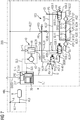
- the rail vehicle 1 also has a first embodiment 20 of the inventive arrangement for drying air L.
- This comprises a controller 30, designated as a whole by 30, a compressor device designated as a whole by 40, an air dryer designated as a whole by 50 and the reservoir R.
- the brake control unit 17 which controls the brake arrangement 13 of the vehicle 1 shown, forms the control device 30.
- the control device 30 is thus an integral part of the brake control unit 17.
- An air dryer inlet E50 is connected via a pneumatic connecting line VL26 to an output A40 of the compressor device 40.
- An air dryer outlet A50 of the air dryer 50 is connected via a pneumatic connecting line VL27 to the main air tank line HBL and thereby further to the reservoir R via the connecting lines VL1 and VL3.
- air dryer 50 a cold-regenerating two-chamber absorption dryer is used.
- one of its two drying chambers 51, 52 is always with the supplied by a compressor 41 of the compressor device 40 compressed air, which is still wet, flows through to dry this moist compressed air, while the other of the drying chambers 51, 52 for regeneration with the dried Compressed air is flowed through.
- FIGS. 1 and 2 This includes the in the FIGS. 1 and 2 shown air dryer 50 next to the two in the usual way with suitable granules filled drying chambers 51, 52 two check valves 53, 54, a regeneration nozzle 55 and a switching means 56th
- the air dryer 50 comprises an air line system formed from the pneumatic connecting lines VL 28 to VL36, which serves on the one hand for introducing the air to be dried L into the drying chambers and on the other hand for conducting air through the drying chambers.
- the line section designated VL34 which is provided with the regeneration nozzle, forms a regeneration line section, over which a part of the dried air used for regeneration of the drying chambers is passed.
- the connecting line VL28 connects the air dryer input E50 to a first terminal A56.1 of the switching means 56.
- the connecting line VL29 connects a second terminal A56.2 of the switching means 56 to a first terminal E51 of the one drying chamber 51.
- connection line VL32 connects a third connection A56.3 of the switching means 56 to a first connection E52 of the other drying chamber 52.
- the compressor device 40 comprises, in addition to the compressor 41, a drive unit 43 connected to the data bus section BUS4 of the signal transmission device by means of an I / O unit 42.
- the drive unit 43 is a drive motor controlled by means of a frequency converter.
- the compressor 41 conveys compressed air into the connecting line VL26, which can be connected via the connecting line V28 and the switching means 56 alternately to one of the two drying chambers 51 or 52.
- the connecting line VL28 is currently in communication with the drying chamber 52.
- the drying chamber 52 is thus in its drying phase.
- the drying chamber 51 - is connected by a fourth port A56.4 of the switching means 56 with a vent E to the atmosphere (outdoors).
- the drying chamber 51 is thus in its regeneration phase.
- the drying chambers 51 and 52 are provided with second ports A51 and A52 opposite to their first ports E51 and E52.
- Connected to the second port A51 of the one drying chamber 51 is the connection line designated VL30, and the second connection A52 of the other drying chamber 52 is connected to the connection line designated VL33.
- the two connection lines VL30 and VL33 respectively open into a branch point P1 or P2, from which the line section denoted VL35 branches off.
- the dried drying air is removed directly from the dried drying chamber for the purpose of regenerating the drying chamber that is not currently active.
- the check valve 53 opening in the direction of the branch point P1 is arranged and in the line section VL34, the check valve 54 opening in the direction of the branch point P2 is arranged.
- the ends of the two connection lines VL31 and VL34 pointing in the direction of the skin air reservoir line HBL form a branch point P3, which is connected to the air dryer exit A50 via the connection line VL36.
- the switching means 56 switches off the in FIG. 1 shown switching position in the in FIG. 2 shown switching position.
- the drying chamber 52 is in its regeneration phase and the drying chamber 51 is in its drying phase.
- the control device 30 is designed to control the switching means 56 to output the switching signal U via an operative connection - here in the form of a control line SL2 - to the switching means 56.
- the control device 30 controls the switching means 56 in such a way that the two drying chambers 51 and 52 can be switched alternately into a drying and a regeneration phase.
- control device 30 is suitably embodied to detect a setpoint S.sub.Soll specified by the compressor device 40 and to output the switchover signal U as a function of the detected setpoint S.sub.Soll.
- the setpoint S.Soll is given to the compressor device 40, for example, from the central vehicle controller 15 via the signal transmission device, the I / O unit 42 and an operative connection SL3, which connects the I / O unit 42 to the drive unit 43.
- the drive unit 43 is a drive motor controlled by means of a frequency converter.
- the setpoint is the frequency converter of the central vehicle control 15 directly as a speed setpoint S n .Soll or as a frequency setpoint S f .Soll given.
- the frequency converter of the drive unit 43 controls its actual speed value to the predetermined speed setpoint S n .Soll.
- the frequency converter derives a target speed and regulates its speed value to the predetermined frequency from the set value S f .Soll derived target rotation speed.
- the compressor device 40 A first transmitted signal value K.EIN indicates that the compressor device 40 is switched on - that is, it is running.
- a second transmitted signal value K.OUT indicates that the compressor device 40 is off - that is, not running.
- the switching signal U determines the control device 30 by means of a computer-based evaluation logic 31 in the following with reference to FIG. 3 more detailed manner.
- the evaluation logic 31 of the control device 30 first acquires the desired value S.sub.setpoint specified for the compressor device 40; S f .oll; S n .soll via the active compound SL4.
- this characteristic curve Q-S-K can also be stored elsewhere and detected by the control device.
- the evaluation logic unit 31 of the control device 30 determines the respective one Setpoints S.Soll.1, S.Soll.2, ..., S.Soll.i corresponding delivery volume values V.1, V.2, ..., Vi, in which case the delivery volume value V from the sum of V.1 + V.2 + ... + Vi.
- the delivery volume intermediate value V.zw is stored at a storage location 33 of the control device.
- the evaluation logic 31 of the control device 30 outputs the switchover signal U when the delivery volume total value V.ges reaches a delivery volume maximum value V.max stored at a storage location 34 of the control device.
- the delivery volume maximum value V.max can also be stored elsewhere and detected by the control device 30.
- the control device 30 It is also essential that the currently determined delivery volume total value V.ges is stored in the control device 30, so that after switching off the compressor device 40 during later reconnection of the Compressor device 40 at the value V.ges, which was current when switching off, as an intermediate value V.zw. can be started.
- the control device stores the displacement total value V.ges at the storage location 33 as the intermediate value V.sub.zw.
- the control device 30 As soon as the delivery volume total V.sub.ges reaches the delivery volume maximum value V.max, not only the switching signal U is output, but the control device 30 also resets the intermediate value V.sub.zw to its initial value zero.
- FIGS. 4 and 5 shown second embodiment 120 of the inventive arrangement differs only in terms of the structural design of the air dryer 150 of the in the FIGS. 1 and 2 shown first embodiment 20.
- FIGS. 4 and 5 designated as a whole with 150 air dryer has in addition to a controlled by the switching signal U switching means 57 in the form of a solenoid valve two medium compressed air controlled shuttle valves 58 and 59, in the illustrated manner via pneumatic connecting lines VL28 to VL41 with two drying chambers 51, 52 two check valves 53rd , 54 and a regeneration nozzle 55 are connected.
- U switching means 57 in the form of a solenoid valve two medium compressed air controlled shuttle valves 58 and 59, in the illustrated manner via pneumatic connecting lines VL28 to VL41 with two drying chambers 51, 52 two check valves 53rd , 54 and a regeneration nozzle 55 are connected.
- the connecting line VL28 is connected to a first connection A58.1 of the shuttle valve 58.
- connection E51 of the air dryer 51 is connected to a second connection A58.2 of the shuttle valve 58 and the connection E52 of the air dryer 52 is connected to a second connection A59.2 of the shuttle valve 58.
- the connecting line VL38 has a branch point P5, which is connected to a vent E1 to the atmosphere (outdoors).
- a branch point P6 in the connection line VL36 is connected via a connecting line VL39 to a first terminal A57.1 of the switching means 57, and a second terminal A57.2 of the switching means 57 is connected via a connecting line VL40 to a pneumatic control input SE58 of the shuttle valve 58.
- a pneumatic control input SE59 of the shuttle valve 59 is connected to the branch point P1 via the connection line VL41.
- a third terminal A57.3 of the switching means 57 is connected to a vent E2 to the atmosphere (outdoors).
- switching position of the switchable by the switching signal U switching means 57 is the drying chamber 51 in their Drying phase and the drying chamber 52 in its regeneration phase.
- the Figures 5 shows the switching means and the two shuttle valves in their switching position after switching, which is now the drying chamber 51 in its regeneration phase and the drying chamber 52 is in its drying phase.
- FIGS. 6 and 7 shown third embodiment 220 of the inventive arrangement differs only in terms of the arrangement of the I / O unit 242 and their connection to the signal transmission device of the in the FIGS. 4 and 5 shown second embodiment 120th
- the I / O unit 242 part of the brake control unit 217, which in the FIG. 1 shown brake assembly 13 of the vehicle 1 controls.
Landscapes
- Engineering & Computer Science (AREA)
- Chemical & Material Sciences (AREA)
- Analytical Chemistry (AREA)
- General Chemical & Material Sciences (AREA)
- Oil, Petroleum & Natural Gas (AREA)
- Chemical Kinetics & Catalysis (AREA)
- Transportation (AREA)
- Mechanical Engineering (AREA)
- Valves And Accessory Devices For Braking Systems (AREA)
- Drying Of Solid Materials (AREA)
- Vehicle Body Suspensions (AREA)
Priority Applications (1)
| Application Number | Priority Date | Filing Date | Title |
|---|---|---|---|
| PL15702682T PL3079958T3 (pl) | 2014-02-07 | 2015-01-23 | Układ i sposób osuszania powietrza oraz pojazd z tego rodzaju układem |
Applications Claiming Priority (2)
| Application Number | Priority Date | Filing Date | Title |
|---|---|---|---|
| DE102014202273.8A DE102014202273A1 (de) | 2014-02-07 | 2014-02-07 | Anordnung und Verfahren zum Trocknen von Luft sowie Fahrzeug mit einer derartigen Anordnung |
| PCT/EP2015/051304 WO2015117836A2 (de) | 2014-02-07 | 2015-01-23 | Anordnung und verfahren zum trocknen von luft sowie fahrzeug mit einer derartigen anordnung |
Publications (2)
| Publication Number | Publication Date |
|---|---|
| EP3079958A2 EP3079958A2 (de) | 2016-10-19 |
| EP3079958B1 true EP3079958B1 (de) | 2018-07-18 |
Family
ID=52450070
Family Applications (1)
| Application Number | Title | Priority Date | Filing Date |
|---|---|---|---|
| EP15702682.4A Active EP3079958B1 (de) | 2014-02-07 | 2015-01-23 | Anordnung und verfahren zum trocknen von luft sowie fahrzeug mit einer derartigen anordnung |
Country Status (6)
| Country | Link |
|---|---|
| EP (1) | EP3079958B1 (pl) |
| CN (1) | CN105980224B (pl) |
| DE (1) | DE102014202273A1 (pl) |
| PL (1) | PL3079958T3 (pl) |
| SA (1) | SA516371626B1 (pl) |
| WO (1) | WO2015117836A2 (pl) |
Families Citing this family (1)
| Publication number | Priority date | Publication date | Assignee | Title |
|---|---|---|---|---|
| EP3530530A1 (en) * | 2018-02-26 | 2019-08-28 | Filkar Otomotiv sanayi ve Ticaret Anonim Sirketi | A brake system with a control unit |
Family Cites Families (8)
| Publication number | Priority date | Publication date | Assignee | Title |
|---|---|---|---|---|
| DE3514473A1 (de) | 1985-04-22 | 1986-10-23 | Knorr-Bremse AG, 8000 München | Vorrichtung zum trocknen von druckluft |
| DE9217999U1 (de) * | 1992-04-18 | 1993-06-17 | MAN Nutzfahrzeuge AG, 8000 München | Druckluftanlage eines Kraftfahrzeuges mit einer Einschaltdauer-Überwachungs-/Warn-Einrichtung für den Luftpresser |
| DE19911741B4 (de) * | 1999-03-16 | 2008-07-31 | Knorr-Bremse Systeme für Nutzfahrzeuge GmbH | Vorrichtung und Verfahren zur Luftaufbereitung, insbesondere für pneumatische Bremsanlagen von Kraftfahrzeugen |
| US6695893B2 (en) * | 2002-03-29 | 2004-02-24 | Bendix Commercial Vehicle Systems Llc | Continuous flow dryer reservoir module dryer system |
| DE102010031306B4 (de) * | 2010-07-14 | 2014-11-27 | Haldex Brake Products Gmbh | Druckluftaufbereitungseinrichtung mit zwei Lufttrocknungskartuschen |
| DE102010054709A1 (de) * | 2010-12-16 | 2012-06-21 | Wabco Gmbh | Lufttrockner-System, Druckluftversorgungsanlage, pneumatisches System und Verfahren zum Betreiben einer Pneumatikanlage |
| DE102011014274A1 (de) * | 2011-03-17 | 2012-09-20 | Knorr-Bremse Systeme für Nutzfahrzeuge GmbH | Lufttrockneradaptermodul, Lufttrocknermodul und Druckluftversorgungseinrichtung |
| DE102012007470B4 (de) * | 2012-04-13 | 2013-11-14 | Knorr-Bremse Systeme für Nutzfahrzeuge GmbH | Druckluftaufbereitungseinrichtung für ein Fahrzeug und Verfahren zum Betreiben einer Druckluftaufbereitungseinrichtung |
-
2014
- 2014-02-07 DE DE102014202273.8A patent/DE102014202273A1/de not_active Withdrawn
-
2015
- 2015-01-23 EP EP15702682.4A patent/EP3079958B1/de active Active
- 2015-01-23 PL PL15702682T patent/PL3079958T3/pl unknown
- 2015-01-23 WO PCT/EP2015/051304 patent/WO2015117836A2/de not_active Ceased
- 2015-01-23 CN CN201580007426.2A patent/CN105980224B/zh active Active
-
2016
- 2016-08-07 SA SA516371626A patent/SA516371626B1/ar unknown
Non-Patent Citations (1)
| Title |
|---|
| None * |
Also Published As
| Publication number | Publication date |
|---|---|
| WO2015117836A3 (de) | 2015-12-23 |
| SA516371626B1 (ar) | 2020-10-19 |
| EP3079958A2 (de) | 2016-10-19 |
| CN105980224B (zh) | 2019-03-08 |
| PL3079958T3 (pl) | 2019-01-31 |
| WO2015117836A2 (de) | 2015-08-13 |
| DE102014202273A1 (de) | 2015-08-13 |
| CN105980224A (zh) | 2016-09-28 |
Similar Documents
| Publication | Publication Date | Title |
|---|---|---|
| EP2407231B2 (de) | Nutzfahrzeug-Druckluftaufbereitungseinrichtung | |
| DE102008030511B4 (de) | Bremsanlage für ein Fahrzeug | |
| EP1451050A1 (de) | Anordnung für ein elektrohydraulisches bremssystem, elektrohydraulisches bremssystem und verfahren zur ansteuerung eines elektrohydraulischen bremssystems sowie tandemhauptbremszylinder | |
| EP2516226A1 (de) | Bremssystem mit druckmodulationszylinder | |
| EP1451051A1 (de) | Elektrohydraulisches bremssystem mit einem pedalwegsimulator zusammengesetzt aus einem federspeicherdruckzylinder und mechanisch gekoppeltem servokolben | |
| DE102018205957A1 (de) | Elektronisch druckregelbare Bremsanlage und Verfahren zur Steuerung einer elektronisch druckregelbaren Bremsanlage | |
| WO1993021047A1 (de) | Hydraulische bremsanlage mit bremsschlupf- und antriebsschlupfregelung | |
| DE102009016440B4 (de) | Getriebeschaltvorrichtung | |
| DE102008000873A1 (de) | Verfahren zur Steuerung einer elektronisch schlupfregelbaren Fahrzeugbremsanlage | |
| EP2027001A1 (de) | Hydraulische anhängerbremsanlage | |
| WO2015043954A1 (de) | Bremsaktor für ein bremssystem eines fahrzeugs sowie verfahren zum abbremsen eines fahrzeugs | |
| DE102019134843A1 (de) | Steuerluftsystem für einen hydrodynamischen Retarder | |
| EP3247603A1 (de) | Vorrichtung und verfahren zum versorgen eines nutzfahrzeugs mit druckluft | |
| WO2012110547A1 (de) | Mehrkreisschutzventil für eine druckluftversorgungseinrichtung eines fahrzeugs und verfahren zum betreiben eines mehrkreisschutzventils | |
| EP2154041B1 (de) | Druckmittelbetätigte Bremsvorrichtung für Kraftfahrzeuge | |
| EP3331735B1 (de) | Kraftfahrzeug mit einem rekuperativen bremsbetrieb | |
| EP2712787A2 (de) | Landwirtschaftliches Fahrzeug mit Servolenkung | |
| DE3626291C2 (de) | Hydraulische Bremsanlage für Kraftfahrzeuge und Verfahren zum Betrieb einer derartigen Bremsanlage | |
| EP3157787A1 (de) | Elektronisch schlupfregelbare fahrzeugbremsanlage | |
| EP3079958A2 (de) | Anordnung und verfahren zum trocknen von luft sowie fahrzeug mit einer derartigen anordnung | |
| EP3461707B1 (de) | Steuersystem einer hydraulisch betätigten bremseinrichtung | |
| EP1695892B1 (de) | Aktive Hydrauliklenkung mit verringertem Überwachungsaufwand | |
| EP3386838B1 (de) | Hydraulische lenkeinrichtung | |
| WO2016030057A1 (de) | Schlupfgeregelte hydraulische zweikreis-fahrzeugbremsanlage und betriebsverfahren dafür | |
| EP3590779B1 (de) | Druckluftaufbereitungseinrichtung und verfahren zum betreiben einer solchen |
Legal Events
| Date | Code | Title | Description |
|---|---|---|---|
| PUAI | Public reference made under article 153(3) epc to a published international application that has entered the european phase |
Free format text: ORIGINAL CODE: 0009012 |
|
| 17P | Request for examination filed |
Effective date: 20160711 |
|
| AK | Designated contracting states |
Kind code of ref document: A2 Designated state(s): AL AT BE BG CH CY CZ DE DK EE ES FI FR GB GR HR HU IE IS IT LI LT LU LV MC MK MT NL NO PL PT RO RS SE SI SK SM TR |
|
| AX | Request for extension of the european patent |
Extension state: BA ME |
|
| DAX | Request for extension of the european patent (deleted) | ||
| RAP1 | Party data changed (applicant data changed or rights of an application transferred) |
Owner name: SIEMENS AKTIENGESELLSCHAFT |
|
| GRAP | Despatch of communication of intention to grant a patent |
Free format text: ORIGINAL CODE: EPIDOSNIGR1 |
|
| STAA | Information on the status of an ep patent application or granted ep patent |
Free format text: STATUS: GRANT OF PATENT IS INTENDED |
|
| INTG | Intention to grant announced |
Effective date: 20180323 |
|
| GRAS | Grant fee paid |
Free format text: ORIGINAL CODE: EPIDOSNIGR3 |
|
| GRAA | (expected) grant |
Free format text: ORIGINAL CODE: 0009210 |
|
| STAA | Information on the status of an ep patent application or granted ep patent |
Free format text: STATUS: THE PATENT HAS BEEN GRANTED |
|
| AK | Designated contracting states |
Kind code of ref document: B1 Designated state(s): AL AT BE BG CH CY CZ DE DK EE ES FI FR GB GR HR HU IE IS IT LI LT LU LV MC MK MT NL NO PL PT RO RS SE SI SK SM TR |
|
| REG | Reference to a national code |
Ref country code: GB Ref legal event code: FG4D Free format text: NOT ENGLISH |
|
| REG | Reference to a national code |
Ref country code: CH Ref legal event code: EP |
|
| REG | Reference to a national code |
Ref country code: IE Ref legal event code: FG4D Free format text: LANGUAGE OF EP DOCUMENT: GERMAN |
|
| REG | Reference to a national code |
Ref country code: AT Ref legal event code: REF Ref document number: 1019004 Country of ref document: AT Kind code of ref document: T Effective date: 20180815 |
|
| REG | Reference to a national code |
Ref country code: DE Ref legal event code: R096 Ref document number: 502015005120 Country of ref document: DE |
|
| REG | Reference to a national code |
Ref country code: NL Ref legal event code: MP Effective date: 20180718 |
|
| REG | Reference to a national code |
Ref country code: NO Ref legal event code: T2 Effective date: 20180718 |
|
| REG | Reference to a national code |
Ref country code: LT Ref legal event code: MG4D |
|
| PG25 | Lapsed in a contracting state [announced via postgrant information from national office to epo] |
Ref country code: NL Free format text: LAPSE BECAUSE OF FAILURE TO SUBMIT A TRANSLATION OF THE DESCRIPTION OR TO PAY THE FEE WITHIN THE PRESCRIBED TIME-LIMIT Effective date: 20180718 |
|
| PG25 | Lapsed in a contracting state [announced via postgrant information from national office to epo] |
Ref country code: FI Free format text: LAPSE BECAUSE OF FAILURE TO SUBMIT A TRANSLATION OF THE DESCRIPTION OR TO PAY THE FEE WITHIN THE PRESCRIBED TIME-LIMIT Effective date: 20180718 Ref country code: GR Free format text: LAPSE BECAUSE OF FAILURE TO SUBMIT A TRANSLATION OF THE DESCRIPTION OR TO PAY THE FEE WITHIN THE PRESCRIBED TIME-LIMIT Effective date: 20181019 Ref country code: IS Free format text: LAPSE BECAUSE OF FAILURE TO SUBMIT A TRANSLATION OF THE DESCRIPTION OR TO PAY THE FEE WITHIN THE PRESCRIBED TIME-LIMIT Effective date: 20181118 Ref country code: RS Free format text: LAPSE BECAUSE OF FAILURE TO SUBMIT A TRANSLATION OF THE DESCRIPTION OR TO PAY THE FEE WITHIN THE PRESCRIBED TIME-LIMIT Effective date: 20180718 Ref country code: LT Free format text: LAPSE BECAUSE OF FAILURE TO SUBMIT A TRANSLATION OF THE DESCRIPTION OR TO PAY THE FEE WITHIN THE PRESCRIBED TIME-LIMIT Effective date: 20180718 Ref country code: SE Free format text: LAPSE BECAUSE OF FAILURE TO SUBMIT A TRANSLATION OF THE DESCRIPTION OR TO PAY THE FEE WITHIN THE PRESCRIBED TIME-LIMIT Effective date: 20180718 |
|
| PG25 | Lapsed in a contracting state [announced via postgrant information from national office to epo] |
Ref country code: AL Free format text: LAPSE BECAUSE OF FAILURE TO SUBMIT A TRANSLATION OF THE DESCRIPTION OR TO PAY THE FEE WITHIN THE PRESCRIBED TIME-LIMIT Effective date: 20180718 Ref country code: LV Free format text: LAPSE BECAUSE OF FAILURE TO SUBMIT A TRANSLATION OF THE DESCRIPTION OR TO PAY THE FEE WITHIN THE PRESCRIBED TIME-LIMIT Effective date: 20180718 Ref country code: HR Free format text: LAPSE BECAUSE OF FAILURE TO SUBMIT A TRANSLATION OF THE DESCRIPTION OR TO PAY THE FEE WITHIN THE PRESCRIBED TIME-LIMIT Effective date: 20180718 |
|
| REG | Reference to a national code |
Ref country code: DE Ref legal event code: R097 Ref document number: 502015005120 Country of ref document: DE |
|
| PG25 | Lapsed in a contracting state [announced via postgrant information from national office to epo] |
Ref country code: ES Free format text: LAPSE BECAUSE OF FAILURE TO SUBMIT A TRANSLATION OF THE DESCRIPTION OR TO PAY THE FEE WITHIN THE PRESCRIBED TIME-LIMIT Effective date: 20180718 Ref country code: IT Free format text: LAPSE BECAUSE OF FAILURE TO SUBMIT A TRANSLATION OF THE DESCRIPTION OR TO PAY THE FEE WITHIN THE PRESCRIBED TIME-LIMIT Effective date: 20180718 Ref country code: RO Free format text: LAPSE BECAUSE OF FAILURE TO SUBMIT A TRANSLATION OF THE DESCRIPTION OR TO PAY THE FEE WITHIN THE PRESCRIBED TIME-LIMIT Effective date: 20180718 Ref country code: CZ Free format text: LAPSE BECAUSE OF FAILURE TO SUBMIT A TRANSLATION OF THE DESCRIPTION OR TO PAY THE FEE WITHIN THE PRESCRIBED TIME-LIMIT Effective date: 20180718 Ref country code: EE Free format text: LAPSE BECAUSE OF FAILURE TO SUBMIT A TRANSLATION OF THE DESCRIPTION OR TO PAY THE FEE WITHIN THE PRESCRIBED TIME-LIMIT Effective date: 20180718 |
|
| PLBE | No opposition filed within time limit |
Free format text: ORIGINAL CODE: 0009261 |
|
| STAA | Information on the status of an ep patent application or granted ep patent |
Free format text: STATUS: NO OPPOSITION FILED WITHIN TIME LIMIT |
|
| PG25 | Lapsed in a contracting state [announced via postgrant information from national office to epo] |
Ref country code: DK Free format text: LAPSE BECAUSE OF FAILURE TO SUBMIT A TRANSLATION OF THE DESCRIPTION OR TO PAY THE FEE WITHIN THE PRESCRIBED TIME-LIMIT Effective date: 20180718 Ref country code: SM Free format text: LAPSE BECAUSE OF FAILURE TO SUBMIT A TRANSLATION OF THE DESCRIPTION OR TO PAY THE FEE WITHIN THE PRESCRIBED TIME-LIMIT Effective date: 20180718 Ref country code: SK Free format text: LAPSE BECAUSE OF FAILURE TO SUBMIT A TRANSLATION OF THE DESCRIPTION OR TO PAY THE FEE WITHIN THE PRESCRIBED TIME-LIMIT Effective date: 20180718 |
|
| 26N | No opposition filed |
Effective date: 20190423 |
|
| PG25 | Lapsed in a contracting state [announced via postgrant information from national office to epo] |
Ref country code: SI Free format text: LAPSE BECAUSE OF FAILURE TO SUBMIT A TRANSLATION OF THE DESCRIPTION OR TO PAY THE FEE WITHIN THE PRESCRIBED TIME-LIMIT Effective date: 20180718 Ref country code: MC Free format text: LAPSE BECAUSE OF FAILURE TO SUBMIT A TRANSLATION OF THE DESCRIPTION OR TO PAY THE FEE WITHIN THE PRESCRIBED TIME-LIMIT Effective date: 20180718 |
|
| REG | Reference to a national code |
Ref country code: CH Ref legal event code: PL |
|
| PG25 | Lapsed in a contracting state [announced via postgrant information from national office to epo] |
Ref country code: LU Free format text: LAPSE BECAUSE OF NON-PAYMENT OF DUE FEES Effective date: 20190123 |
|
| REG | Reference to a national code |
Ref country code: BE Ref legal event code: MM Effective date: 20190131 |
|
| REG | Reference to a national code |
Ref country code: IE Ref legal event code: MM4A |
|
| PG25 | Lapsed in a contracting state [announced via postgrant information from national office to epo] |
Ref country code: BE Free format text: LAPSE BECAUSE OF NON-PAYMENT OF DUE FEES Effective date: 20190131 |
|
| PG25 | Lapsed in a contracting state [announced via postgrant information from national office to epo] |
Ref country code: CH Free format text: LAPSE BECAUSE OF NON-PAYMENT OF DUE FEES Effective date: 20190131 Ref country code: LI Free format text: LAPSE BECAUSE OF NON-PAYMENT OF DUE FEES Effective date: 20190131 |
|
| PG25 | Lapsed in a contracting state [announced via postgrant information from national office to epo] |
Ref country code: IE Free format text: LAPSE BECAUSE OF NON-PAYMENT OF DUE FEES Effective date: 20190123 |
|
| PG25 | Lapsed in a contracting state [announced via postgrant information from national office to epo] |
Ref country code: TR Free format text: LAPSE BECAUSE OF FAILURE TO SUBMIT A TRANSLATION OF THE DESCRIPTION OR TO PAY THE FEE WITHIN THE PRESCRIBED TIME-LIMIT Effective date: 20180718 |
|
| PG25 | Lapsed in a contracting state [announced via postgrant information from national office to epo] |
Ref country code: PT Free format text: LAPSE BECAUSE OF FAILURE TO SUBMIT A TRANSLATION OF THE DESCRIPTION OR TO PAY THE FEE WITHIN THE PRESCRIBED TIME-LIMIT Effective date: 20181118 Ref country code: MT Free format text: LAPSE BECAUSE OF FAILURE TO SUBMIT A TRANSLATION OF THE DESCRIPTION OR TO PAY THE FEE WITHIN THE PRESCRIBED TIME-LIMIT Effective date: 20180718 |
|
| PG25 | Lapsed in a contracting state [announced via postgrant information from national office to epo] |
Ref country code: CY Free format text: LAPSE BECAUSE OF FAILURE TO SUBMIT A TRANSLATION OF THE DESCRIPTION OR TO PAY THE FEE WITHIN THE PRESCRIBED TIME-LIMIT Effective date: 20180718 |
|
| PG25 | Lapsed in a contracting state [announced via postgrant information from national office to epo] |
Ref country code: HU Free format text: LAPSE BECAUSE OF FAILURE TO SUBMIT A TRANSLATION OF THE DESCRIPTION OR TO PAY THE FEE WITHIN THE PRESCRIBED TIME-LIMIT; INVALID AB INITIO Effective date: 20150123 |
|
| PG25 | Lapsed in a contracting state [announced via postgrant information from national office to epo] |
Ref country code: MK Free format text: LAPSE BECAUSE OF FAILURE TO SUBMIT A TRANSLATION OF THE DESCRIPTION OR TO PAY THE FEE WITHIN THE PRESCRIBED TIME-LIMIT Effective date: 20180718 |
|
| PGFP | Annual fee paid to national office [announced via postgrant information from national office to epo] |
Ref country code: BG Payment date: 20250123 Year of fee payment: 11 |
|
| PGFP | Annual fee paid to national office [announced via postgrant information from national office to epo] |
Ref country code: NO Payment date: 20250108 Year of fee payment: 11 |
|
| PGFP | Annual fee paid to national office [announced via postgrant information from national office to epo] |
Ref country code: GB Payment date: 20260210 Year of fee payment: 12 |
|
| PGFP | Annual fee paid to national office [announced via postgrant information from national office to epo] |
Ref country code: DE Payment date: 20260320 Year of fee payment: 12 |
|
| PGFP | Annual fee paid to national office [announced via postgrant information from national office to epo] |
Ref country code: AT Payment date: 20251210 Year of fee payment: 12 |
|
| PGFP | Annual fee paid to national office [announced via postgrant information from national office to epo] |
Ref country code: FR Payment date: 20260122 Year of fee payment: 12 |
|
| PGFP | Annual fee paid to national office [announced via postgrant information from national office to epo] |
Ref country code: PL Payment date: 20260115 Year of fee payment: 12 |