EP3079944B1 - Herstellen einer lade- und einer zugeordneten kommunikationsverbindung - Google Patents
Herstellen einer lade- und einer zugeordneten kommunikationsverbindung Download PDFInfo
- Publication number
- EP3079944B1 EP3079944B1 EP15716048.2A EP15716048A EP3079944B1 EP 3079944 B1 EP3079944 B1 EP 3079944B1 EP 15716048 A EP15716048 A EP 15716048A EP 3079944 B1 EP3079944 B1 EP 3079944B1
- Authority
- EP
- European Patent Office
- Prior art keywords
- communication device
- communication
- charging
- unit
- vehicle
- Prior art date
- Legal status (The legal status is an assumption and is not a legal conclusion. Google has not performed a legal analysis and makes no representation as to the accuracy of the status listed.)
- Active
Links
Images

Classifications
-
- B—PERFORMING OPERATIONS; TRANSPORTING
- B60—VEHICLES IN GENERAL
- B60L—PROPULSION OF ELECTRICALLY-PROPELLED VEHICLES; SUPPLYING ELECTRIC POWER FOR AUXILIARY EQUIPMENT OF ELECTRICALLY-PROPELLED VEHICLES; ELECTRODYNAMIC BRAKE SYSTEMS FOR VEHICLES IN GENERAL; MAGNETIC SUSPENSION OR LEVITATION FOR VEHICLES; MONITORING OPERATING VARIABLES OF ELECTRICALLY-PROPELLED VEHICLES; ELECTRIC SAFETY DEVICES FOR ELECTRICALLY-PROPELLED VEHICLES
- B60L53/00—Methods of charging batteries, specially adapted for electric vehicles; Charging stations or on-board charging equipment therefor; Exchange of energy storage elements in electric vehicles
- B60L53/30—Constructional details of charging stations
- B60L53/305—Communication interfaces
-
- B—PERFORMING OPERATIONS; TRANSPORTING
- B60—VEHICLES IN GENERAL
- B60L—PROPULSION OF ELECTRICALLY-PROPELLED VEHICLES; SUPPLYING ELECTRIC POWER FOR AUXILIARY EQUIPMENT OF ELECTRICALLY-PROPELLED VEHICLES; ELECTRODYNAMIC BRAKE SYSTEMS FOR VEHICLES IN GENERAL; MAGNETIC SUSPENSION OR LEVITATION FOR VEHICLES; MONITORING OPERATING VARIABLES OF ELECTRICALLY-PROPELLED VEHICLES; ELECTRIC SAFETY DEVICES FOR ELECTRICALLY-PROPELLED VEHICLES
- B60L53/00—Methods of charging batteries, specially adapted for electric vehicles; Charging stations or on-board charging equipment therefor; Exchange of energy storage elements in electric vehicles
- B60L53/10—Methods of charging batteries, specially adapted for electric vehicles; Charging stations or on-board charging equipment therefor; Exchange of energy storage elements in electric vehicles characterised by the energy transfer between the charging station and the vehicle
- B60L53/12—Inductive energy transfer
-
- B—PERFORMING OPERATIONS; TRANSPORTING
- B60—VEHICLES IN GENERAL
- B60L—PROPULSION OF ELECTRICALLY-PROPELLED VEHICLES; SUPPLYING ELECTRIC POWER FOR AUXILIARY EQUIPMENT OF ELECTRICALLY-PROPELLED VEHICLES; ELECTRODYNAMIC BRAKE SYSTEMS FOR VEHICLES IN GENERAL; MAGNETIC SUSPENSION OR LEVITATION FOR VEHICLES; MONITORING OPERATING VARIABLES OF ELECTRICALLY-PROPELLED VEHICLES; ELECTRIC SAFETY DEVICES FOR ELECTRICALLY-PROPELLED VEHICLES
- B60L53/00—Methods of charging batteries, specially adapted for electric vehicles; Charging stations or on-board charging equipment therefor; Exchange of energy storage elements in electric vehicles
- B60L53/30—Constructional details of charging stations
- B60L53/35—Means for automatic or assisted adjustment of the relative position of charging devices and vehicles
- B60L53/36—Means for automatic or assisted adjustment of the relative position of charging devices and vehicles by positioning the vehicle
-
- B—PERFORMING OPERATIONS; TRANSPORTING
- B60—VEHICLES IN GENERAL
- B60L—PROPULSION OF ELECTRICALLY-PROPELLED VEHICLES; SUPPLYING ELECTRIC POWER FOR AUXILIARY EQUIPMENT OF ELECTRICALLY-PROPELLED VEHICLES; ELECTRODYNAMIC BRAKE SYSTEMS FOR VEHICLES IN GENERAL; MAGNETIC SUSPENSION OR LEVITATION FOR VEHICLES; MONITORING OPERATING VARIABLES OF ELECTRICALLY-PROPELLED VEHICLES; ELECTRIC SAFETY DEVICES FOR ELECTRICALLY-PROPELLED VEHICLES
- B60L53/00—Methods of charging batteries, specially adapted for electric vehicles; Charging stations or on-board charging equipment therefor; Exchange of energy storage elements in electric vehicles
- B60L53/30—Constructional details of charging stations
- B60L53/35—Means for automatic or assisted adjustment of the relative position of charging devices and vehicles
- B60L53/38—Means for automatic or assisted adjustment of the relative position of charging devices and vehicles specially adapted for charging by inductive energy transfer
-
- B—PERFORMING OPERATIONS; TRANSPORTING
- B60—VEHICLES IN GENERAL
- B60L—PROPULSION OF ELECTRICALLY-PROPELLED VEHICLES; SUPPLYING ELECTRIC POWER FOR AUXILIARY EQUIPMENT OF ELECTRICALLY-PROPELLED VEHICLES; ELECTRODYNAMIC BRAKE SYSTEMS FOR VEHICLES IN GENERAL; MAGNETIC SUSPENSION OR LEVITATION FOR VEHICLES; MONITORING OPERATING VARIABLES OF ELECTRICALLY-PROPELLED VEHICLES; ELECTRIC SAFETY DEVICES FOR ELECTRICALLY-PROPELLED VEHICLES
- B60L53/00—Methods of charging batteries, specially adapted for electric vehicles; Charging stations or on-board charging equipment therefor; Exchange of energy storage elements in electric vehicles
- B60L53/50—Charging stations characterised by energy-storage or power-generation means
- B60L53/53—Batteries
-
- B—PERFORMING OPERATIONS; TRANSPORTING
- B60—VEHICLES IN GENERAL
- B60L—PROPULSION OF ELECTRICALLY-PROPELLED VEHICLES; SUPPLYING ELECTRIC POWER FOR AUXILIARY EQUIPMENT OF ELECTRICALLY-PROPELLED VEHICLES; ELECTRODYNAMIC BRAKE SYSTEMS FOR VEHICLES IN GENERAL; MAGNETIC SUSPENSION OR LEVITATION FOR VEHICLES; MONITORING OPERATING VARIABLES OF ELECTRICALLY-PROPELLED VEHICLES; ELECTRIC SAFETY DEVICES FOR ELECTRICALLY-PROPELLED VEHICLES
- B60L53/00—Methods of charging batteries, specially adapted for electric vehicles; Charging stations or on-board charging equipment therefor; Exchange of energy storage elements in electric vehicles
- B60L53/60—Monitoring or controlling charging stations
- B60L53/65—Monitoring or controlling charging stations involving identification of vehicles or their battery types
-
- B—PERFORMING OPERATIONS; TRANSPORTING
- B60—VEHICLES IN GENERAL
- B60R—VEHICLES, VEHICLE FITTINGS, OR VEHICLE PARTS, NOT OTHERWISE PROVIDED FOR
- B60R19/00—Wheel guards; Radiator guards, e.g. grilles; Obstruction removers; Fittings damping bouncing force in collisions
- B60R19/02—Bumpers, i.e. impact receiving or absorbing members for protecting vehicles or fending off blows from other vehicles or objects
- B60R19/48—Bumpers, i.e. impact receiving or absorbing members for protecting vehicles or fending off blows from other vehicles or objects combined with, or convertible into, other devices or objects, e.g. bumpers combined with road brushes, bumpers convertible into beds
-
- B—PERFORMING OPERATIONS; TRANSPORTING
- B60—VEHICLES IN GENERAL
- B60Y—INDEXING SCHEME RELATING TO ASPECTS CROSS-CUTTING VEHICLE TECHNOLOGY
- B60Y2200/00—Type of vehicle
- B60Y2200/90—Vehicles comprising electric prime movers
- B60Y2200/91—Electric vehicles
-
- Y—GENERAL TAGGING OF NEW TECHNOLOGICAL DEVELOPMENTS; GENERAL TAGGING OF CROSS-SECTIONAL TECHNOLOGIES SPANNING OVER SEVERAL SECTIONS OF THE IPC; TECHNICAL SUBJECTS COVERED BY FORMER USPC CROSS-REFERENCE ART COLLECTIONS [XRACs] AND DIGESTS
- Y02—TECHNOLOGIES OR APPLICATIONS FOR MITIGATION OR ADAPTATION AGAINST CLIMATE CHANGE
- Y02T—CLIMATE CHANGE MITIGATION TECHNOLOGIES RELATED TO TRANSPORTATION
- Y02T10/00—Road transport of goods or passengers
- Y02T10/60—Other road transportation technologies with climate change mitigation effect
- Y02T10/70—Energy storage systems for electromobility, e.g. batteries
-
- Y—GENERAL TAGGING OF NEW TECHNOLOGICAL DEVELOPMENTS; GENERAL TAGGING OF CROSS-SECTIONAL TECHNOLOGIES SPANNING OVER SEVERAL SECTIONS OF THE IPC; TECHNICAL SUBJECTS COVERED BY FORMER USPC CROSS-REFERENCE ART COLLECTIONS [XRACs] AND DIGESTS
- Y02—TECHNOLOGIES OR APPLICATIONS FOR MITIGATION OR ADAPTATION AGAINST CLIMATE CHANGE
- Y02T—CLIMATE CHANGE MITIGATION TECHNOLOGIES RELATED TO TRANSPORTATION
- Y02T10/00—Road transport of goods or passengers
- Y02T10/60—Other road transportation technologies with climate change mitigation effect
- Y02T10/7072—Electromobility specific charging systems or methods for batteries, ultracapacitors, supercapacitors or double-layer capacitors
-
- Y—GENERAL TAGGING OF NEW TECHNOLOGICAL DEVELOPMENTS; GENERAL TAGGING OF CROSS-SECTIONAL TECHNOLOGIES SPANNING OVER SEVERAL SECTIONS OF THE IPC; TECHNICAL SUBJECTS COVERED BY FORMER USPC CROSS-REFERENCE ART COLLECTIONS [XRACs] AND DIGESTS
- Y02—TECHNOLOGIES OR APPLICATIONS FOR MITIGATION OR ADAPTATION AGAINST CLIMATE CHANGE
- Y02T—CLIMATE CHANGE MITIGATION TECHNOLOGIES RELATED TO TRANSPORTATION
- Y02T90/00—Enabling technologies or technologies with a potential or indirect contribution to GHG emissions mitigation
- Y02T90/10—Technologies relating to charging of electric vehicles
- Y02T90/12—Electric charging stations
-
- Y—GENERAL TAGGING OF NEW TECHNOLOGICAL DEVELOPMENTS; GENERAL TAGGING OF CROSS-SECTIONAL TECHNOLOGIES SPANNING OVER SEVERAL SECTIONS OF THE IPC; TECHNICAL SUBJECTS COVERED BY FORMER USPC CROSS-REFERENCE ART COLLECTIONS [XRACs] AND DIGESTS
- Y02—TECHNOLOGIES OR APPLICATIONS FOR MITIGATION OR ADAPTATION AGAINST CLIMATE CHANGE
- Y02T—CLIMATE CHANGE MITIGATION TECHNOLOGIES RELATED TO TRANSPORTATION
- Y02T90/00—Enabling technologies or technologies with a potential or indirect contribution to GHG emissions mitigation
- Y02T90/10—Technologies relating to charging of electric vehicles
- Y02T90/14—Plug-in electric vehicles
-
- Y—GENERAL TAGGING OF NEW TECHNOLOGICAL DEVELOPMENTS; GENERAL TAGGING OF CROSS-SECTIONAL TECHNOLOGIES SPANNING OVER SEVERAL SECTIONS OF THE IPC; TECHNICAL SUBJECTS COVERED BY FORMER USPC CROSS-REFERENCE ART COLLECTIONS [XRACs] AND DIGESTS
- Y02—TECHNOLOGIES OR APPLICATIONS FOR MITIGATION OR ADAPTATION AGAINST CLIMATE CHANGE
- Y02T—CLIMATE CHANGE MITIGATION TECHNOLOGIES RELATED TO TRANSPORTATION
- Y02T90/00—Enabling technologies or technologies with a potential or indirect contribution to GHG emissions mitigation
- Y02T90/10—Technologies relating to charging of electric vehicles
- Y02T90/16—Information or communication technologies improving the operation of electric vehicles
- Y02T90/167—Systems integrating technologies related to power network operation and communication or information technologies for supporting the interoperability of electric or hybrid vehicles, i.e. smartgrids as interface for battery charging of electric vehicles [EV] or hybrid vehicles [HEV]
-
- Y—GENERAL TAGGING OF NEW TECHNOLOGICAL DEVELOPMENTS; GENERAL TAGGING OF CROSS-SECTIONAL TECHNOLOGIES SPANNING OVER SEVERAL SECTIONS OF THE IPC; TECHNICAL SUBJECTS COVERED BY FORMER USPC CROSS-REFERENCE ART COLLECTIONS [XRACs] AND DIGESTS
- Y04—INFORMATION OR COMMUNICATION TECHNOLOGIES HAVING AN IMPACT ON OTHER TECHNOLOGY AREAS
- Y04S—SYSTEMS INTEGRATING TECHNOLOGIES RELATED TO POWER NETWORK OPERATION, COMMUNICATION OR INFORMATION TECHNOLOGIES FOR IMPROVING THE ELECTRICAL POWER GENERATION, TRANSMISSION, DISTRIBUTION, MANAGEMENT OR USAGE, i.e. SMART GRIDS
- Y04S30/00—Systems supporting specific end-user applications in the sector of transportation
- Y04S30/10—Systems supporting the interoperability of electric or hybrid vehicles
- Y04S30/14—Details associated with the interoperability, e.g. vehicle recognition, authentication, identification or billing
Definitions
- the invention relates to methods and apparatus for producing a charging and an associated communication link.
- EP 2 717 428 A1 discloses a charging system for contactless charging of an electric vehicle.
- a data transmission can take place via a first communication path or a second communication path, wherein the second communication path has a limited transmission range compared to the first communication path.
- US 2014/002015 A1 relates to a system for wireless charging of an electric vehicle.
- Data transmission between the charging station and the electric vehicle takes place via conventional radio links such as Bluetooth, Zigbee, mobile radio or WLAN.
- DE 10 2012 012 860 A1 relates to an apparatus and a unit for providing an association connection for a charging system for wireless charging of an electric vehicle.
- the at least one communication unit is designed as an ultrasound unit, a radar unit, an ultrasound sensor or a radar sensor.
- This method is advantageous because already existing components of the vehicle, e.g. the ultrasonic sensors or radar sensors for which communication between the vehicle and the charging station can be used. As a result, a cost-effective solution is presented.
- secure communication between the vehicle and the charging station can be made possible, which then ensures protection of an authorized transmission of energy via the charging connection, e.g. using authorization and authentication.
- a start of the energy transmission via the charging connection can only be permitted after establishing the communication connection.
- a particular advantage of the invention is achieved in that the at least one communication unit is used integrated in a front of the vehicle, in particular in a bumper. As a result, no external conversions are necessary on the vehicle, so that the method can be implemented inexpensively.
- a radiation characteristic of the at least one communication unit of the second communication device is set up such that radiated signals strike at least one of the communication units of the first communication device.
- a distance between the first and second communication device is reduced before establishing the communication connection by guiding the second communication device in the direction of the first communication device. This procedure also results in a further improvement of a secure communication connection, as disrupting or compromising the communication connection is made more difficult.
- At least one first communication unit of a plurality of communication units of the first communication device is selected such that the at least one first communication unit with respect to the further plurality of communication units has a shorter distance to the second communication device.
- the at least one communication unit is designed as an ultrasound unit, a radar unit, an ultrasound sensor or a radar sensor.
- the second communication device can have a fourth unit, wherein at least one of the method steps described above can be implemented and executed with the fourth unit.
- the advantages of the second communication device are analogous to the advantages of the method.
- the at least one communication unit is designed as an ultrasound unit, a radar unit, an ultrasound sensor or a radar sensor.
- the first communication device may further comprise an eighth unit, wherein with the eighth unit at least one of the method steps described above can be implemented and executed.
- the advantages of the first communication device are analogous to the advantages of the method.
- the invention comprises a system with a first communication device and a second communication device.
- the advantages are analogous to the advantages of the process.
- ultrasonic units or ultrasonic sensors instead of ultrasound units, other communication units, e.g. Radar units or radar sensors or units or sensors are used communicating in a different frequency band than ultrasound and radar.
- Radar units or radar sensors or units or sensors are used communicating in a different frequency band than ultrasound and radar.
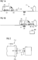
- FIG. 1a shows a starting situation of a vehicle F in the direction of a charging station LS.
- the vehicle F has a first charging device LE1 for receiving electrical energy for charging its battery BAT.
- the vehicle has a first communication device KE1, which in this example is attached to the bumper of the vehicle. As indicated by an arrow P, the vehicle moves in the direction of the charging station.
- the charging station has a second charging device LE2, which, after successful positioning of the first charging device via the second charging device, can, for example, inductively transmit electrical energy to the first charging device for charging the battery of the vehicle.
- the charging station has via a second communication device KE2 to subsequently also be able to record a communication connection KV with the first communication device of the vehicle.
- the vehicle Before the communication link can be set up, the vehicle must position its first charging device with exact position above the second charging device of the charging station. Only when this positioning is successfully completed can a communication be established via the communication link.
- the second communication device is aligned relative to the first communication device, alternative also the first communication device relative to the second communication device after performing the positioning such that the communication link for wireless exchange of information INF is configured.
- the alignment takes place in such a way that when the communication connection is received, the information can only be received between the first and second communication device so that further communication devices KEX can not receive the information.
- FIG. 2 shows an arrangement of the first and second communication device in the form that thereby a reception of the information is inhibited by the further communication device.
- the first and the second communication device each have at least one ultrasound unit that can respectively send and / or receive information.
- the ultrasound unit can be designed as an ultrasound sensor.
- the second communication device restricts a radiation characteristic AC of the at least one ultrasound unit such that it can only be received in a very limited environment of the ultrasound unit of the first communication device, for example within a radius of the first communication device of FIG cm.
- the second communication device can, for example, measure the position of the first communication device. This can be done, for example, by the ultrasound unit itself, since the signal is usually reflected after emission from the surface of the vehicle and by the second communication device thereby a duration of the outward and return signal can be determined. Depending on the determined distance, a distance between the first and the second communication device can be actively reduced by positioning the second communication device closer to the first communication device. This is in FIG. 3 to see in which the second communication device is first pushed to position A and then after determining the distance between the first and second communication device, for example, to 5 cm distance to the first communication device to position B.
- the charging station may detect the model of the vehicle and thus a location of the first communication device that is specific to a respective model of a vehicle.
- the detection can be carried out for example with the aid of a video camera and a downstream pattern processing in the charging station.
- a position of the second communication device for example, a distance or a height of the turn-off characteristic can be adjusted via ground depending on the model of the respective vehicle.
- a surface condition in an environment of the first communication device can be determined by the second communication device.
- the surface condition in the environment of the first communication device can also be determined on the basis of the model of the vehicle.
- the turn-off is changed to avoid unwanted radiation of information to other communication devices, for example by reducing a distance of the second communication device to the second communication device or by limiting a radiation angle of the ultrasonic waves by the second communication device.
- the ultrasound unit or the ultrasound units of the first communication device can be active, which have a shortest distance to the at least one ultrasound unit of the second communication device, e.g. the two of the ultrasound units of the first communication device are selected, which have a shortest distance to the at least one ultrasound unit of the second communication device compared to the other ultrasound units of the first communication device.
- the second communication device KE2 can have a fourth unit E4, with the fourth unit E4 implementations and alternatives of the invention being implementable and executable.
- first communication device KE1 have an eighth unit E8, with the eighth unit E8 further developments and alternatives of the invention can be implemented and executed.
- the units of the first and second communication device can be implemented and realized at least partially in software and / or in a combination of software and hardware.
- the components of the units realized in software can be implemented in the form of machine-readable code, wherein this code can be stored on a memory unit and transmitted from there via a connection to at least one processor for execution.
- an input and / or output unit can be connected to the processor, via which the processor exchanges information with communication units, for example via the ultrasonic sensors.
- the invention can be used in the field of electrical refueling of vehicles, such as electric scooters, electric cars, electric buses or electric trucks.
- vehicles such as electric scooters, electric cars, electric buses or electric trucks.
- self-propelled unit such as. self-sufficient vacuum cleaners, service robots, boats, ships and the like.
Landscapes
- Engineering & Computer Science (AREA)
- Mechanical Engineering (AREA)
- Power Engineering (AREA)
- Transportation (AREA)
- Electric Propulsion And Braking For Vehicles (AREA)
- Charge And Discharge Circuits For Batteries Or The Like (AREA)
Description
- Die Erfindung betrifft Verfahren und Vorrichtungen zum Herstellen von einer Lade- und einer zugeordneten Kommunikationsverbindung.
- Gegenwärtig werden verschiedene Konzepte zum Laden von Elektrofahrzeugen an Ladestationen diskutiert. Hierbei ist es nicht nur notwendig eine Ladeverbindung zwischen der Ladestation und dem Fahrzeug zu haben, über die elektrischer Strom in die Batterie des Fahrzeugs gespeist werden kann, sondern auch vor, während und nach dem Ladevorgang müssen Informationen zwischen der Ladestation und dem Fahrzeug ausgetauscht werden. Diese Informationen betreffen beispielsweise eine Authentifizierung des Fahrzeugs an der Ladestation, eine Überwachung des Ladevorgangs oder auch ein Abrechnen der bezogenen elektrischen Energie nach Beendigung des Ladevorgangs.
- Um eine Kommunikation zwischen Fahrzeug und Ladestation sicher zu gestalten, das heißt um Angreifer ein Stören der Kommunikation zu erschweren, ist bekannt eine Kommunikationsverbindung über ein Ladekabel, das physikalisch die Ladestation mit dem Fahrzeug verbindet, zu führen. Hierbei ist jedoch nachteilig, dass zum Einen das Stecken des Ladekabels in das Fahrzeug und in die Ladestation aufwendig ist und zum Anderen das Kabel beispielsweise durch Vandalismus beschädigt und/oder zerstört werden kann. Hierzu wäre es von Vorteil die Ladeverbindung als auch die Kommunikationsverbindung drahtlos zu gestalten, da hierdurch die oben genannten Nachteile des Ladekabels vermieden werden können.
-
EP 2 717 428 A1 offenbart ein Ladesystem für ein berührungsloses Laden eines Elektrofahrzeugs. Eine Datenübertragung kann dabei über einen ersten Kommunikationsweg oder einen zweiten Kommunikationsweg erfolgen, wobei der zweite Kommunikationsweg eine im Vergleich zum ersten Kommunikationsweg eine eingeschränkte Übertragungsreichweite aufweist. -
US 2014/002015 A1 betrifft ein System zum kabellosen Laden eines Elektrofahrzeugs. Die Datenübertragung zwischen Ladestation und Elektrofahrzeug erfolgt dabei über konventionelle Funkverbindungen wie Bluetooth, Zigbee, Mobilfunk oder WLAN erfolgen. -
DE 10 2012 012 860 A1 betrifft eine Vorrichtung und eine Einheit zum Bereitstellen einer Assoziationsverbindung für ein Ladesystem zum kabellosen Aufladen eines Elektrofahrzeugs. - Somit ist es die Aufgabe der folgenden Erfindung Verfahren und Vorrichtungen anzugeben, die ein Herstellen von einer Ladeverbindung und einer zugeordneten Kommunikationsverbindung derart gewährleisten, dass eine Assoziation der Ladeverbindung und der Kommunikationsverbindung und somit eine Manipulation der Assoziation der Ladeverbindung und der Kommunikationsverbindung vermieden wird.
- Diese Aufgabe wird durch die unabhängigen Ansprüche gelöst. Weiterbildungen der Erfindung sind den abhängigen Ansprüchen zu entnehmen.
- Die Erfindung betrifft ein Verfahren zum Herstellen von einer Ladeverbindung und einer zugeordneten Kommunikationsverbindung zwischen einer Ladestation und einem Fahrzeug, wobei das Fahrzeug eine erste Ladeeinrichtung und eine erste Kommunikationsrichtung und die Ladestation eine zweite Ladeeinrichtung und eine zweite Kommunikationseinrichtung aufweisen, dadurch gekennzeichnet, dass das Verfahren folgende Schritte durchläuft:
- Positionieren der ersten Ladeeinrichtung in Bezug auf die zweite Ladeeinrichtung derart, dass Energie zum Laden einer Batterie des Fahrzeugs über die Ladeverbindung übertragen werden kann;
- Ausrichten der zweiten Kommunikationseinrichtung gegenüber der ersten Kommunikationseinrichtung nach Durchführen der Positionierung derart, dass durch die Kommunikationsverbindung ein drahtloser Austausch von Informationen derart durchgeführt werden kann, dass ein Empfang der Informationen durch eine weitere Kommunikationseinrichtung unterbunden wird;
- Einrichten der ersten Kommunikationseinrichtung und der zweiten Kommunikationseinrichtung derart, dass die Informationen mittels jeweils zumindest einer Kommunikationseinheit ausgesendet und /oder empfangen werden.
- Hierbei wird die zumindest eine Kommunikationseinheit als eine Ultraschalleinheit, eine Radareinheit, ein Ultraschallsensor oder ein Radarsensor ausgebildet. Dieses Verfahren ist vorteilhaft, da bereits vorhandene Komponenten des Fahrzeugs, wie z.B. die Ultraschallsensoren oder Radarsensoren, für die Kommunikation zwischen Fahrzeug und Ladesäule einsetzbar sind. Hierdurch ist eine kostengünstige Lösung vorgestellt. Zudem kann durch die spezifische Anordnung der ersten und zweiten Kommunikationseinrichtung eine sichere Kommunikation zwischen dem Fahrzeug und der Ladesäule ermöglicht werden, die dann eine Absicherung einer berechtigten Übertragung von Energie über die Ladeverbindung, z.B. mittels Autorisierung und Authentifizierung ermöglichen kann. Zudem kann ein Start der Energieübertragung über die Ladeverbindung erst nach Herstellen der Kommunikationsverbindung zugelassen werden.
- Ein besonderer Vorteil der Erfindung wird dadurch erzielt, dass die zumindest eine Kommunikationseinheit in einer Front des Fahrzeugs, insbesondere in einem Stoßfänger, integriert verwendet wird. Hierdurch sind an dem Fahrzeug keine äußerlichen Umbauen notwendig, wodurch das Verfahren kostengünstig umgesetzt werden kann.
- Gemäß der Erfindung wird eine Abstrahlcharakteristik der zumindest einen Kommunikationseinheit der zweiten Kommunikationseinrichtung derart eingerichtet, dass abgestrahlte Signale auf zumindest eine der Kommunikationseinheiten der ersten Kommunikationseinrichtung treffen. Hierdurch wird eine Kommunikation sicherer ausgestaltet, da durch die Weiterbildung ein Kompromittieren der Kommunikation zwischen Fahrzeug und Ladesäule weiter erschwert wird.
- Im Rahmen diesem Aspekt wird die Abstrahlcharakteristik nach der Positionierung in Abhängigkeit von zumindest einem der folgenden Bedingungen individuell eingestellt:
- Lage der ersten Kommunikationseinrichtung zu der zweiten Kommunikationseinrichtung;
- Modell des Fahrzeugs;
- Oberflächenbeschaffenheit einer Umgebung der ersten Kommunikationseinrichtung.
- Hierdurch wird eine Sicherheit bei der Herstellung der Kommunikationsverbindung weiter erhöht. Einem Angreifer der Kommunikationsverbindung und der Ladeverbindung wird der Angriff hierdurch erschwert.
- In einer Weiterbildung des Verfahren wird ein Abstand zwischen der ersten und zweiten Kommunikationseinrichtung vor einem Herstellen der Kommunikationsverbindung durch Führen der zweiten Kommunikationseinrichtung in Richtung der ersten Kommunikationseinrichtung verringert wird. Auch diese Vorgehensweise resultiert in einer weiteren Verbesserung einer sicheren Kommunikationsverbindung, da ein Stören bzw. Kompromittieren der Kommunikationsverbindung weiter erschwert wird.
- In einer bevorzugten Weiterbildung der Erfindung wird zumindest eine erste Kommunikationseinheit aus mehreren Kommunikationseinheiten der ersten Kommunikationseinrichtung derart ausgewählt, dass die zumindest eine erste Kommunikationseinheit gegenüber der weiteren mehreren Kommunikationseinheiten einen kürzeren Abstand zu der zweiten Kommunikationseinrichtung aufweist. Hierdurch wird eine weitere Steigerung einer Sicherheit der Kommunikationsverbindung erzielt, da ein örtliches Gebiet zwischen Fahrzeug und Ladesäule, in dem die Wellen der Kommunikationseinheiten übertragen werden weiter eingeschränkt werden.
- Die Erfindung betrifft ferner eine zweite Kommunikationseinrichtung einer Ladestation zum Herstellen einer, einer Ladeverbindung zugeordneten, Kommunikationsverbindung zwischen der Ladestation und einem Fahrzeug, wobei das Fahrzeug eine erste Ladeeinrichtung und eine erste Kommunikationsrichtung und die Ladestation neben der zweiten Ladeeinrichtung und eine zweite Kommunikationseinrichtung aufweisen, gekennzeichnet durch folgende Einheiten:
- Erste Einheit zum Herstellen der Ladeverbindung nach Positionieren der ersten Ladeeinrichtung in Bezug auf die zweite Ladeeinrichtung derart, dass Energie zum Laden einer Batterie des Fahrzeugs über die Ladeverbindung übertragbar ist;
- Zweite Einheit zum Ausrichten der zweiten Kommunikationseinrichtung gegenüber der ersten Kommunikationseinrichtung nach Durchführen der Positionierung derart, dass durch die Kommunikationsverbindung ein drahtloser Austausch von Informationen derart durchgeführt werden kann, dass ein Empfang der Informationen durch eine weitere Kommunikationseinrichtung unterbunden ist;
- Dritte Einheit zum Einrichten der zweiten Kommunikationseinrichtung gegenüber der ersten Kommunikationseinrichtung derart, dass die Informationen mittels jeweils zumindest einer Kommunikationseinheit aussendbar und /oder empfangbar sind.
- Hierbei ist die zumindest eine Kommunikationseinheit als eine Ultraschalleinheit, eine Radareinheit, ein Ultraschallsensor oder ein Radarsensor ausgebildet.
- Zudem kann die zweite Kommunikationseinrichtung eine vierte Einheit aufweisen, wobei mit der vierten Einheit zumindest einer der zuvor dargestellten Verfahrensschritte implementierbar und ausführbar ist.
- Die Vorteile der zweiten Kommunikationseinrichtung sind analog zu den Vorteilen des Verfahrens.
- Zudem betrifft die Erfindung auch eine erste Kommunikationseinrichtung eines Fahrzeugs zum Herstellen einer, einer Ladeverbindung zugeordneten, Kommunikationsverbindung zwischen einer Ladestation und dem Fahrzeug, wobei das Fahrzeug eine erste Ladeeinrichtung und die erste Kommunikationsrichtung und die Ladestation eine zweite Ladeeinrichtung und eine zweite Kommunikationseinrichtung aufweisen, gekennzeichnet durch folgende Einheiten:
- Fünfte Einheit zum Positionieren der ersten Ladeeinrichtung in Bezug auf die zweite Ladeeinrichtung derart, dass Energie zum Laden einer Batterie des Fahrzeugs über die Ladeverbindung übertragbar ist;
- Sechste Einheit zum Ausrichten der ersten Kommunikationseinrichtung gegenüber der zweiten Kommunikationseinrichtung nach Durchführen der Positionierung derart, dass durch die Kommunikationsverbindung ein drahtloser Austausch von Informationen derart durchgeführt werden kann, dass ein Empfang der Informationen durch eine weitere Kommunikationseinrichtung unterbunden ist;
- Siebte Einheit zum Einrichten der ersten Kommunikationseinrichtung gegenüber der zweiten Kommunikationseinrichtung derart, dass die Informationen mittels jeweils zumindest einer Kommunikationseinheit aussendbar und /oder empfangbar sind.
- Hierbei ist die zumindest eine Kommunikationseinheit als eine Ultraschalleinheit, eine Radareinheit, ein Ultraschallsensor oder ein Radarsensor ausgebildet.
- Die erste Kommunikationseinrichtung kann ferner eine achte Einheit aufweisen, wobei mit der achten Einheit zumindest einer der zuvor dargestellten Verfahrensschritte implementierbar und ausführbar ist.
- Die Vorteile der ersten Kommunikationseinrichtung sind analog zu den Vorteilen des Verfahrens.
- Schließlich umfasst die Erfindung ein System mit einer ersten Kommunikationseinrichtung und einer zweiten Kommunikationseinrichtung. Die Vorteile sind analog zu den Vorteilen des Verfahrens.
- Die Erfindung und ihre Varianten werden anhand von Figuren näher erläutert. Im Einzelnen zeigen:
- Figur 1a
- eine Anfahrsituation eines Elektrofahrzeugs in Richtung einer Ladestation;
- Figur 1b
- eine Ladesituation, bei der das Fahrzeug zum Laden seiner Batterie bei der Ladestation positioniert ist;
- Figur 2
- ein Aufbau einer Kommunikationsverbindung mit einer ersten und zweiten Kommunikationseinrichtung; und
- Figur 3
- eine Variante eines Aufbaus einer Kommunikationsverbindung mit der ersten und zweiten Kommunikationseinrichtung;
- Figur 4
- einen jeweiligen Aufbau der ersten und zweiten Kommunikationseinrichtung.
- Elemente mit gleicher Funktion und Wirkungsweise sind in den Figuren mit denselben Bezugszeichen versehen.
- Die folgenden Beispiele stellen die Erfindung anhand von Ultraschalleinheiten, bzw. Ultraschallsensoren, vor. Anstelle von Ultraschalleinheiten können auch andere Kommunikationseinheiten, wie z.B. Radareinheiten bzw. Radarsensoren oder Einheiten bzw. Sensoren kommunizierend in einem anderen Frequenzband als Ultraschall und Radar eingesetzt werden.
-
Figur 1a zeigt eine Anfahrsituation eines Fahrzeugs F in Richtung einer Ladestation LS. Das Fahrzeug F weist eine erste Ladeeinrichtung LE1 zum Aufnehmen elektrischer Energie zum Laden seiner Batterie BAT auf. Zudem verfügt das Fahrzeug über eine erste Kommunikationseinrichtung KE1, welche in diesem Beispiel an der Stoßstange des Fahrzeugs angebracht ist. Wie mit einem Pfeil P angedeutet, bewegt sich das Fahrzeug in Richtung der Ladestation. - Die Ladestation verfügt über eine zweite Ladeeinrichtung LE2, die nach erfolgreicher Positionierung der ersten Ladeeinrichtung über der zweiten Ladeeinrichtung elektrische Energie an die erste Ladeeinrichtung zum Laden der Batterie des Fahrzeugs bspw. induktiv übertragen kann. Zudem verfügt die Ladestation über eine zweite Kommunikationseinrichtung KE2 um nachfolgend auch eine Kommunikationsverbindung KV mit der ersten Kommunikationseinrichtung des Fahrzeugs aufnehmen zu können.
- Bevor die Kommunikationsverbindung aufgebaut werden kann, muss das Fahrzeug seine erste Ladeeinrichtung positionsgenau über der zweiten Ladeeinrichtung der Ladestation positionieren. Erst wenn diese Positionierung erfolgreich abgeschlossen ist kann eine Kommunikation über die Kommunikationsverbindung hergestellt werden. Hierzu wird die zweite Kommunikationseinrichtung gegenüber der ersten Kommunikationseinrichtung, alternative auch die erste Kommunikationseinrichtung gegenüber der zweiten Kommunikationseinrichtung, nach Durchführen der Positionierung derart ausgerichtet, dass die Kommunikationsverbindung zum drahtlosen Austausch von Informationen INF ausgestaltet ist. Die Ausrichtung findet derart statt, dass bei Aufnahme der Kommunikationsverbindung die Informationen nur zwischen der ersten und zweiten Kommunikationseinrichtung empfangbar sind, sodass weitere Kommunikationseinrichtungen KEX die Informationen nicht empfangen können.
-
Figur 2 zeigt eine Anordnung der ersten und zweiten Kommunikationseinrichtung in der Gestalt, dass hierdurch ein Empfang der Informationen durch die weitere Kommunikationseinrichtung unterbunden wird. In dem vorliegenden Beispiel weisen die erste und die zweite Kommunikationseinrichtung jeweils zumindest eine Ultraschalleinheit auf, der jeweils Informationen senden und/oder empfangen kann. Die Ultraschalleinheit kann als Ultraschallsensor ausgebildet sein. Zum Unterbinden des Abhörens der Information durch die weitere Kommunikationseinrichtung schränkt die zweite Kommunikationseinrichtung eine Abstrahlungscharakteristik AC der zumindest einen Ultraschalleinheit derart ein, dass diese nur in einer eng begrenzten Umgebung der Ultraschalleinheit der ersten Kommunikationseinrichtung empfangbar ist, beispielsweise in einem Radius um die erste Kommunikationseinrichtung von 5 cm. - Zur Beeinflussung der Abschaltcharakteristik eines Signals kann die zweite Kommunikationseinrichtung beispielsweise die Lage der ersten Kommunikationseinrichtung vermessen. Dies kann beispielsweise durch die Ultraschalleinheit selbst erfolgen, da das Signal in der Regel nach Ausstrahlen von der Oberfläche des Fahrzeugs reflektiert und durch die zweite Kommunikationseinrichtung hierdurch eine Laufzeit des Hin- und Rücksignals ermittelt werden kann. In Abhängigkeit von der ermittelten Distanz kann ein Abstand zwischen der ersten und der zweiten Kommunikationseinrichtung aktiv vermindert werden, indem die zweite Kommunikationseinrichtung näher an die erste Kommunikationseinrichtung positioniert wird. Dies ist in
Figur 3 zu sehen, in der die zweite Kommunikationseinrichtung zunächst an Position A und dann nach Ermittlung der Distanz zwischen erster und zweiter Kommunikationseinrichtung beispielsweise auf 5 cm Abstand zur ersten Kommunikationseinrichtung auf Position B geschoben wird. - In einer alternativen oder zusätzlichen Ausführungsform kann durch die Ladestation das Modell des Fahrzeugs und somit eine Lage der ersten Kommunikationseinrichtung, die spezifisch für ein jeweiliges Modell eines Fahrzeugs ist, erkannt werden. Die Erkennung kann beispielsweise mit Hilfe einer Videokamera und einer nachgeschalteten Musterverarbeitung in der Ladestation durchgeführt werden. In Abhängigkeit von dem erkannten Modell und damit von der Lage der ersten Kommunikationseinrichtung kann eine Lage der zweiten Kommunikationseinrichtung zum Beispiel ein Abstand oder eine Höhe der Abschaltcharakteristik über Boden in Abhängigkeit des Modells des jeweiligen Fahrzeugs angepasst werden.
- Ferner kann eine Oberflächenbeschaffenheit in einer Umgebung der ersten Kommunikationseinrichtung durch die zweite Kommunikationseinrichtung ermittelt werden. Hierbei kann beispielsweise mit Hilfe der Reflexionseigenschaften der durch die zweite Kommunikationseinrichtung abgestrahlten Ultraschallwelle, die durch die Oberfläche des Fahrzeugs reflektiert wird, auf eine Oberflächenbeschaffenheit des Fahrzeugs rückgeschlossen werden. Ferner kann auch auf Grundlage des Modells des Fahrzeugs die Oberflächenbeschaffenheit in der Umgebung der ersten Kommunikationseinrichtung ermittelt werden. Je nach Oberflächenbeschaffenheit der Umgebung wird die Abschaltcharakteristik verändert um ungewünschte Abstrahlung von Informationen zu weiteren Kommunikationseinrichtungen zu vermeiden, beispielsweise durch Reduzierung eines Abstands der zweiten Kommunikationseinrichtung zur zweiten Kommunikationseinrichtung oder durch Eingrenzung eines Abstrahlwinkels der Ultraschallwellen durch die zweite Kommunikationseinrichtung.
- Heutzutage sind Fahrzeuge mit mehreren Ultraschalleinheiten z.B. in der Stoßstange ausgestattet, um beispielsweise einen Fahrzeuglenker beim Einparken auf Hindernisse vor oder hinter dem Fahrzeug aufmerksam zu machen. Um eine Sicherheit bei der Kommunikation zwischen der ersten und der zweiten Kommunikationseinrichtung zu erhöhen kann in der ersten Kommunikationseinrichtung nur eine oder zwei der mehreren Ultraschalleinheiten zum Austausch von Information eingesetzt werden. Insbesondere kann die Ultraschalleinheit bzw. können die Ultraschalleinheiten der ersten Kommunikationseinrichtung aktiv sein, die einen kürzesten Abstand zu der zumindest einen Ultraschalleinheit der zweiten Kommunikationseinrichtung aufweisen, z.B. werden die zwei der Ultraschalleinheiten der ersten Kommunikationseinrichtung selektiert, die im Vergleich zu den anderen Ultraschalleinheiten der ersten Kommunikationseinrichtung einen kürzesten Abstand zu der zumindest einen Ultraschalleinheit der zweiten Kommunikationseinrichtung haben.
- Die zweite Kommunikationseinrichtung kann durch folgende Einheiten realisiert werden:
- Erste Einheit E1 zum Herstellen der Ladeverbindung LV nach Positionieren der ersten Ladeeinrichtung LE1 in Bezug auf die zweite Ladeeinrichtung LE2 derart, dass Energie zum Laden einer Batterie BAT des Fahrzeugs F über die Ladeverbindung LV übertragbar ist;
- Zweite Einheit E2 zum Ausrichten der zweiten Kommunikationseinrichtung KE2 gegenüber der ersten Kommunikationseinrichtung KE1 nach Durchführen der Positionierung derart, dass durch die Kommunikationsverbindung KV ein drahtloser Austausch von Informationen INF derart durchgeführt werden kann, dass ein Empfang der Informationen INF durch eine weitere Kommunikationseinrichtung KEX unterbunden ist;
- Dritte Einheit E3 zum Einrichten der zweiten Kommunikationseinrichtung KE2 gegenüber der ersten Kommunikationseinrichtung KE1 derart, dass die Informationen INF mittels jeweils zumindest einer Kommunikationseinheit aussendbar und /oder empfangbar sind.
- Ferner kann die zweite Kommunikationseinrichtung KE2 eine vierte Einheit E4 aufweisen, wobei mit der vierten Einheit E4 Weiterbildungen und Alternativen der Erfindung implementierbar und ausführbar sind.
- Die erste Kommunikationseinrichtung KE1 kann durch folgende Einheiten implementiert und realisiert werden:
- Fünfte Einheit E5 zum Positionieren der ersten Ladeeinrichtung LE1 in Bezug auf die zweite Ladeeinrichtung LE2 derart, dass Energie zum Laden einer Batterie BAT des Fahrzeugs F über die Ladeverbindung LV übertragbar ist;
- Sechste Einheit E6 zum Ausrichten der ersten Kommunikationseinrichtung KE1 gegenüber der zweiten Kommunikationseinrichtung KE2 nach Durchführen der Positionierung derart, dass durch die Kommunikationsverbindung KV ein drahtloser Austausch von Informationen INF derart durchgeführt werden kann, dass ein Empfang der Informationen INF durch eine weitere Kommunikationseinrichtung KEX unterbunden ist;
- Siebte Einheit E7 zum Einrichten der ersten Kommunikationseinrichtung KE1 gegenüber der zweiten Kommunikationseinrichtung KE2 derart, dass die Informationen INF mittels jeweils zumindest einer Kommunikationseinheit aussendbar und /oder empfangbar sind.
- Ferner kann die erste Kommunikationseinrichtung KE1 eine achte Einheit E8 aufweisen, wobei mit der achten Einheit E8 Weiterbildungen und Alternativen der Erfindung implementierbar und ausführbar sind.
- Die Einheiten der ersten und zweiten Kommunikationseinrichtung, siehe
Figur 4 , können zumindest teilweise in Software und/oder in einer Kombination aus Soft- und Hardware implementiert und realisiert werden. Dabei können die in Software realisierten Bestandteile der Einheiten in Form von maschinenlesbaren Code implementiert werden, wobei dieser Code auf einer Speichereinheit abgelegt und von dort über eine Verbindung zu zumindest einen Prozessor zur Ausführung übertragen werden kann. Zudem kann an dem Prozessor ferner eine Ein- und/oder Ausgabeeinheit angeschlossen sein, über die der Prozessor Informationen mit Kommunikationseinheiten austauscht, z.B. über die Ultraschallsensoren. - Die Erfindung ist einsetzbar im Umfeld eines elektrischen Betankens von Fahrzeugen, wie Elektroroller, Elektroauto, Elektrobus oder Elektrolastkraftwagen. Zudem ist im Rahmen der Erfindung unter Fahrzeug jede Art von sich selbst fortbewegende Einheit, wie z.B. autark agierende Staubsauger, Serviceroboter, Boote, Schiffe und ähnliches, zu verstehen.
Claims (7)
- Verfahren zum Herstellen von einer Ladeverbindung (LV) und einer zugeordneten Kommunikationsverbindung (KV) zwischen einer Ladestation (LS) und einem Fahrzeug (F), wobei das Fahrzeug (F) eine erste Ladeeinrichtung (LE1) und eine erste Kommunikationsrichtung (KE1) und die Ladestation (LS) eine zweite Ladeeinrichtung (LE2) und eine zweite Kommunikationseinrichtung (KE2) aufweisen, wobei das Verfahren folgende Schritte durchläuft:- Positionieren der ersten Ladeeinrichtung (LE1) in Bezug auf die zweite Ladeeinrichtung (LE2) derart, dass Energie zum Laden einer Batterie (BAT) des Fahrzeugs (F) über die Ladeverbindung (LV) übertragen werden kann;- Ausrichten der zweiten Kommunikationseinrichtung (KE2) gegenüber der ersten Kommunikationseinrichtung (KE1) nach Durchführen der Positionierung derart, dass durch die Kommunikationsverbindung (KV) ein drahtloser Austausch von Informationen (INF) derart durchgeführt werden kann, dass ein Empfang der Informationen (INF) durch eine weitere Kommunikationseinrichtung (KEX) unterbunden wird;- Einrichten der ersten Kommunikationseinrichtung (KE1) und der zweiten Kommunikationseinrichtung (KE2) derart, dass die Informationen (INF) mittels jeweils zumindest einer Kommunikationseinheit ausgesendet und /oder empfangen werden;wobei die zumindest eine Kommunikationseinheit eine Ultraschalleinheit, eine Radareinheit, einen Ultraschallsensor oder einen Radarsensor umfasst, und
wobei, eine Abstrahlcharakteristik (AC) der zumindest einen Kommunikationseinheit der zweiten Kommunikationseinrichtung (KE2) derart eingerichtet wird, dass abgestrahlte Signale auf zumindest eine der Kommunikationseinheiten, der ersten Kommunikationseinrichtung (KE1) treffen, und
die Abstrahlcharakteristik (AC) nach der Positionierung in Abhängigkeit von zumindest einem der folgenden Bedingungen individuell eingestellt wird:- Lage (PLC) der ersten Kommunikationseinrichtung (KE1) zu der zweiten Kommunikationseinrichtung (KE2);- Oberflächenbeschaffenheit (MAT) einer Umgebung der ersten Kommunikationseinrichtung (KE1). - Verfahren nach Anspruch 1, bei dem die zumindest eine Kommunikationseinheit in einer Front (SFG) des Fahrzeugs, insbesondere in einem Stoßfänger, integriert verwendet wird.
- Verfahren nach einem der vorhergehenden Ansprüche, bei dem ein Abstand (ABS) zwischen der ersten und zweiten Kommunikationseinrichtung (K1, KE2) vor einem Herstellen der Kommunikationsverbindung (KV) durch Führen der zweiten Kommunikationseinrichtung (KE2) in Richtung der ersten Kommunikationseinrichtung (KE1) verringert wird.
- Verfahren nach einem der vorhergehenden Ansprüche, bei dem eine erste Kommunikationseinheit (UX) aus mehreren Kommunikationseinheiten der ersten Kommunikationseinrichtung (KE1) derart ausgewählt wird, dass die erste Kommunikationseinheit (UX) gegenüber der mehreren Kommunikationseinheiten einen kürzesten Abstand zu der zweiten Kommunikationseinrichtung KE2 aufweist.
- Zweite Kommunikationseinrichtung (KE2) einer Ladestation (LS) zum Herstellen einer, einer Ladeverbindung (LV) zugeordneten, Kommunikationsverbindung (KV) zwischen der Ladestation (LS) und einem Fahrzeug (F), wobei das Fahrzeug (F) eine erste Ladeeinrichtung (LE1) und eine erste Kommunikationsrichtung (KE1) aufweist, und die Ladestation (LS) neben der zweiten Ladeeinrichtung (LE2) die zweite Kommunikationseinrichtung (KE2) aufweist, wobei die zweite Kommunikationseinrichtung (KE2) folgende Einheiten umfasst:- Erste Einheit (E1) zum Herstellen der Ladeverbindung (LV) nach Positionieren der ersten Ladeeinrichtung (LE1) in Bezug auf die zweite Ladeeinrichtung (LE2) derart, dass Energie zum Laden einer Batterie (BAT) des Fahrzeugs (F) über die Ladeverbindung (LV) übertragbar ist;- Zweite Einheit (E2) zum Ausrichten der zweiten Kommunikationseinrichtung (KE2) gegenüber der ersten Kommunikationseinrichtung (KE1) nach Durchführen der Positionierung derart, dass durch die Kommunikationsverbindung (KV) ein drahtloser Austausch von Informationen (INF) derart durchgeführt werden kann, dass ein Empfang der Informationen (INF) durch eine weitere Kommunikationseinrichtung (KEX) unterbunden ist;- Dritte Einheit (E3) zum Einrichten der zweiten Kommunikationseinrichtung (KE2) gegenüber der ersten Kommunikationseinrichtung (KE1) derart, dass die Informationen (INF) mittels jeweils zumindest einer Kommunikationseinheit aussendbar und /oder empfangbar sind;wobei die zweite Kommunikationseinrichtung (KE2) die zumindest eine Kommunkationseinheit umfasst; wobei die zumindest eine Kommunikationseinheit eine Ultraschalleinheit, eine Radareinheit, einen Ultraschallsensor oder einen Radarsensor umfasst, und
wobei, eine Abstrahlcharakteristik (AC) der zumindest einen Kommunikationseinheit der zweiten Kommunikationseinrichtung (KE2) derart eingerichtet ist, dass abgestrahlte Signale auf zumindest eine der Kommunikationseinheiten, der ersten Kommunikationseinrichtung (KE1) treffen, und
die Abstrahlcharakteristik (AC) nach der Positionierung in Abhängigkeit von zumindest einem der folgenden Bedingungen individuell eingestellt wird:- Lage (PLC) der ersten Kommunikationseinrichtung (KE1) zu der zweiten Kommunikationseinrichtung (KE2);- Oberflächenbeschaffenheit (MAT) einer Umgebung der ersten Kommunikationseinrichtung (KE1). - Erste Kommunikationseinrichtung (KE1) eines Fahrzeugs (F) zum Herstellen einer, einer Ladeverbindung (LV) zugeordneten, Kommunikationsverbindung (KV) zwischen einer Ladestation (LS) und dem Fahrzeug (F), wobei das Fahrzeug (F) eine erste Ladeeinrichtung (LE1) und die erste Kommunikationsrichtung (KE1) und die Ladestation (LS) eine zweite Ladeeinrichtung (LE2) und eine zweite Kommunikationseinrichtung (KE2) aufweisen, wobei die erste Kommunikationseinrichtung (KE1) folgende Einheiten umfasst:- Fünfte Einheit (E5) zum Positionieren der ersten Ladeeinrichtung (LE1) in Bezug auf die zweite Ladeeinrichtung (LE2) derart, dass Energie zum Laden einer Batterie (BAT) des Fahrzeugs (F) über die Ladeverbindung (LV) übertragbar ist;- Sechste Einheit (E6) zum Ausrichten der ersten Kommunikationseinrichtung (KE1) gegenüber der zweiten Kommunikationseinrichtung (KE2) nach Durchführen der Positionierung derart, dass durch die Kommunikationsverbindung (KV) ein drahtloser Austausch von Informationen (INF) derart durchgeführt werden kann, dass ein Empfang der Informationen (INF) durch eine weitere Kommunikationseinrichtung (KEX) unterbunden ist;- Siebte Einheit (E7) zum Einrichten der ersten Kommunikationseinrichtung (KE1) gegenüber der zweiten Kommunikationseinrichtung (KE2) derart, dass die Informationen (INF) mittels jeweils zumindest einer Kommunikationseinheit aussendbar und /oder empfangbar sind;wobei die erste Kommunikationseinrichtung (KE1) die zumindest eine Kommunikationseinheit umfasst; dadurch gekennzeichnet, dass die zumindest eine Kommunikationseinheit eine Ultraschalleinheit, eine Radareinheit, einen Ultraschallsensor oder einen Radarsensor umfasst.
- System (SYS) umfassend
eine erste Kommunikationseinrichtung (KE1) gemäß Anspruch 6, und eine zweite Kommunikationseinrichtung (KE2) gemäß Anspruch 5.
Applications Claiming Priority (2)
| Application Number | Priority Date | Filing Date | Title |
|---|---|---|---|
| DE102014207440.1A DE102014207440A1 (de) | 2014-04-17 | 2014-04-17 | Herstellen einer Lade- und einer zugeordneten Kommunikationsverbindung |
| PCT/EP2015/058054 WO2015158704A1 (de) | 2014-04-17 | 2015-04-14 | Herstellen einer lade- und einer zugeordneten kommunikationsverbindung |
Publications (2)
| Publication Number | Publication Date |
|---|---|
| EP3079944A1 EP3079944A1 (de) | 2016-10-19 |
| EP3079944B1 true EP3079944B1 (de) | 2018-10-03 |
Family
ID=52829102
Family Applications (1)
| Application Number | Title | Priority Date | Filing Date |
|---|---|---|---|
| EP15716048.2A Active EP3079944B1 (de) | 2014-04-17 | 2015-04-14 | Herstellen einer lade- und einer zugeordneten kommunikationsverbindung |
Country Status (6)
| Country | Link |
|---|---|
| US (1) | US10227018B2 (de) |
| EP (1) | EP3079944B1 (de) |
| KR (1) | KR102001115B1 (de) |
| CN (1) | CN106458047B (de) |
| DE (1) | DE102014207440A1 (de) |
| WO (1) | WO2015158704A1 (de) |
Families Citing this family (4)
| Publication number | Priority date | Publication date | Assignee | Title |
|---|---|---|---|---|
| US11465517B2 (en) | 2019-05-16 | 2022-10-11 | Abb Schweiz Ag | Electric charging connection for heavy vehicles |
| CN112092655B (zh) * | 2019-06-18 | 2023-01-31 | 湖南中车智行科技有限公司 | 充电站通信系统、方法和充电站 |
| DE102021201215A1 (de) | 2021-02-09 | 2022-08-11 | Robert Bosch Gesellschaft mit beschränkter Haftung | Verfahren zur Kommunikation zwischen einer Lade- oder Betankungseinrichtung und einem Fahrzeug |
| DE102021204359A1 (de) | 2021-04-30 | 2022-11-03 | Robert Bosch Gesellschaft mit beschränkter Haftung | Verfahren und System zur mechanischen Kommunikation zwischen einer Infrastrukturkomponente und einem Fahrzeug |
Family Cites Families (13)
| Publication number | Priority date | Publication date | Assignee | Title |
|---|---|---|---|---|
| DE102008009208A1 (de) * | 2008-02-15 | 2009-08-20 | Gunter Arnold | Navigationssystem für einen autonomen mobilen Roboter, insbesondere Rasenmähroboter |
| US9873347B2 (en) * | 2009-03-12 | 2018-01-23 | Wendell Brown | Method and apparatus for automatic charging of an electrically powered vehicle |
| DE102009021818A1 (de) * | 2009-05-18 | 2010-11-25 | Fachhochschule Aachen | Ortungssystem |
| CN102118069B (zh) | 2009-12-31 | 2014-12-17 | 上海汽车集团股份有限公司 | 高效率的非接触式充电系统和利用该系统充电的车辆 |
| US20110221387A1 (en) * | 2010-03-09 | 2011-09-15 | Robert Louis Steigerwald | System and method for charging an energy storage system for an electric or hybrid-electric vehicle |
| US9184633B2 (en) * | 2011-02-03 | 2015-11-10 | Denso Corporation | Non-contact power supply control device, non-contact power supply system, and non-contact power charge system |
| JP5879748B2 (ja) * | 2011-05-27 | 2016-03-08 | 日産自動車株式会社 | 非接触給電装置、車両及び非接触給電システム |
| US9931952B2 (en) * | 2012-06-27 | 2018-04-03 | Qualcomm Incorporated | Electric vehicle wireless charging with monitoring of duration of charging operational mode |
| DE102012012860A1 (de) * | 2012-06-28 | 2014-01-23 | Siemens Aktiengesellschaft | Bereitstellen einer Assoziationsverbindung |
| DE102012216660A1 (de) * | 2012-09-18 | 2014-03-20 | Siemens Aktiengesellschaft | Verfahren zum Positionieren oder Auswählen einer Induktivität und zugehörige Vorrichtungen |
| DE102013209235A1 (de) * | 2013-05-17 | 2014-11-20 | Siemens Aktiengesellschaft | Verfahren und Vorrichtung zur Positionsbestimmung |
| US9937811B2 (en) * | 2013-07-19 | 2018-04-10 | Ford Global Technologies, Llc | Vehicle authentication for a BEV charger |
| KR101622788B1 (ko) * | 2014-03-04 | 2016-05-20 | 고려대학교 산학협력단 | 전력소모를 줄일 수 있는 고효율 출력 드라이버 및 상기 출력 드라이버를 포함하는 송신기 |
-
2014
- 2014-04-17 DE DE102014207440.1A patent/DE102014207440A1/de not_active Withdrawn
-
2015
- 2015-04-14 EP EP15716048.2A patent/EP3079944B1/de active Active
- 2015-04-14 WO PCT/EP2015/058054 patent/WO2015158704A1/de active Application Filing
- 2015-04-14 CN CN201580020243.4A patent/CN106458047B/zh active Active
- 2015-04-14 KR KR1020167032175A patent/KR102001115B1/ko active IP Right Grant
- 2015-04-14 US US15/129,918 patent/US10227018B2/en active Active
Non-Patent Citations (1)
| Title |
|---|
| None * |
Also Published As
| Publication number | Publication date |
|---|---|
| KR102001115B1 (ko) | 2019-07-17 |
| CN106458047B (zh) | 2020-03-17 |
| EP3079944A1 (de) | 2016-10-19 |
| CN106458047A (zh) | 2017-02-22 |
| WO2015158704A1 (de) | 2015-10-22 |
| US10227018B2 (en) | 2019-03-12 |
| US20170136909A1 (en) | 2017-05-18 |
| DE102014207440A1 (de) | 2015-10-22 |
| KR20160145751A (ko) | 2016-12-20 |
Similar Documents
| Publication | Publication Date | Title |
|---|---|---|
| EP3079944B1 (de) | Herstellen einer lade- und einer zugeordneten kommunikationsverbindung | |
| WO2018197065A1 (de) | Authentifizierungssystem eines fahrzeugs | |
| EP3119637B1 (de) | Verbindungseinheit und verfahren zur herstellung einer assoziationsverbindung zwischen elektrofahrzeug und ladestation | |
| WO2016005104A1 (de) | Vorrichtung und verfahren zum betreiben eines induktiven ladesystems | |
| DE102011088917B4 (de) | Zugangsanordnung im Verfahren zum Betreiben einer derartigen Zugangsanordnung | |
| DE102014219842A1 (de) | Verfahren zur Bestimmung einer Anordnung eines Elektrofahrzeugs und Anordnungsbestimmungseinheit | |
| DE102013016880A1 (de) | Verfahren zur Positionierung eines Fahrzeugs an einer induktiven Ladestation | |
| DE102015208624A1 (de) | Vorrichtung zum Einleiten eines autonomen Einparkens eines Fahrzeugs | |
| WO2018197116A1 (de) | Verfahren zum betreiben eines authentifizierungssystems und authentifizierungssystem | |
| DE102014101086A1 (de) | Mobilgerät für ein schlüsselloses Zugangs- oder Betätigungssystem für Kraftfahrzeuge | |
| EP3350015B1 (de) | Verfahren zur ermittlung einer eine relativposition eines kraftfahrzeugs zu einer stationären, anzufahrenden ladeeinrichtung beschreibenden positionsinformation und anordnung aus einem kraftfahrzeug und einer stationären, anzufahrenden ladeeinrichtung | |
| DE102014212821A1 (de) | Vorrichtung und Verfahren zur Erfassung eines Schwenkwinkels zwischen einem Fahrzeug und einer Anhängervorrichtung | |
| DE102013217713A1 (de) | Sendespule zur induktiven Energieübertragung, Ladestation, Verfahren zum Positionieren einer induktiven Energieübertragungsvorrichtung und Verfahren zum Detektieren eines Fremdobjekts zwischen einer Sendespule und einer Empfangsspule | |
| DE102014015577A1 (de) | Vorrichtung, System und Verfahren zum Beseitigen eines Objekts zum induktiven Aufladen einer Traktionsbatterie eines Fahrzeugs | |
| DE102016120162A1 (de) | Verfahren zum Überwachen einer Umgebung einer mit einem Kraftfahrzeug gekoppelten Anhängervorrichtung mithilfe von Abstandssensoren der Anhängervorrichtung, Sensorsystem, Anhängervorrichtung sowie Gespann | |
| DE102019002375A1 (de) | Verfahren zum zumindest teilweise autonomen Manövrieren eines Fahrzeugs in einem vorgegebenen Ladeareal und Funkvorrichtung für ein Fahrzeug zum zumindest teilweise autonomen Manövrieren des Fahrzeugs in einem vorgegebenen Ladeareal | |
| DE102017000077B3 (de) | Elektronisches Kopplungssystem | |
| DE102016203047B4 (de) | Verfahren und Vorrichtungen für insbesondere ein Kraftfahr-Zugzugangs- und/oder -Start-System | |
| EP3864427B1 (de) | Vorrichtung zur positionsbestimmung eines relativ zu einem fahrzeug bewegbaren gegenstandes und ein damit ausgestattetes fahrzeug | |
| WO2018010881A1 (de) | Verfahren zum betrieb einer ladevorrichtung zur induktiven energieübertragung | |
| EP3734559A1 (de) | Sicherheitssystem für ein fahrzeug | |
| EP2904423B1 (de) | Verfahren und vorrichtung zur latenzzeitoptimierung bei einer abstandsmessung mittels mehrerer sensoren | |
| WO2008095959A1 (de) | Verfahren und vorrichtung zum lokalisieren von an einem fahrzeug montierten reifen | |
| DE102017102620A1 (de) | Verfahren zur Positionsbestimmung eines mobilen BLE-Geräts | |
| DE102017121021A1 (de) | Verfahren zum Betreiben einer Detektionsvorrichtung eines Fahrzeugs zur Erfassung von Objekten und Detektionsvorrichtung |
Legal Events
| Date | Code | Title | Description |
|---|---|---|---|
| PUAI | Public reference made under article 153(3) epc to a published international application that has entered the european phase |
Free format text: ORIGINAL CODE: 0009012 |
|
| 17P | Request for examination filed |
Effective date: 20160715 |
|
| AK | Designated contracting states |
Kind code of ref document: A1 Designated state(s): AL AT BE BG CH CY CZ DE DK EE ES FI FR GB GR HR HU IE IS IT LI LT LU LV MC MK MT NL NO PL PT RO RS SE SI SK SM TR |
|
| AX | Request for extension of the european patent |
Extension state: BA ME |
|
| DAV | Request for validation of the european patent (deleted) | ||
| DAX | Request for extension of the european patent (deleted) | ||
| RAP1 | Party data changed (applicant data changed or rights of an application transferred) |
Owner name: SIEMENS AKTIENGESELLSCHAFT |
|
| GRAP | Despatch of communication of intention to grant a patent |
Free format text: ORIGINAL CODE: EPIDOSNIGR1 |
|
| STAA | Information on the status of an ep patent application or granted ep patent |
Free format text: STATUS: GRANT OF PATENT IS INTENDED |
|
| INTG | Intention to grant announced |
Effective date: 20180504 |
|
| GRAS | Grant fee paid |
Free format text: ORIGINAL CODE: EPIDOSNIGR3 |
|
| GRAA | (expected) grant |
Free format text: ORIGINAL CODE: 0009210 |
|
| STAA | Information on the status of an ep patent application or granted ep patent |
Free format text: STATUS: THE PATENT HAS BEEN GRANTED |
|
| AK | Designated contracting states |
Kind code of ref document: B1 Designated state(s): AL AT BE BG CH CY CZ DE DK EE ES FI FR GB GR HR HU IE IS IT LI LT LU LV MC MK MT NL NO PL PT RO RS SE SI SK SM TR |
|
| REG | Reference to a national code |
Ref country code: GB Ref legal event code: FG4D Free format text: NOT ENGLISH |
|
| REG | Reference to a national code |
Ref country code: CH Ref legal event code: EP Ref country code: AT Ref legal event code: REF Ref document number: 1048227 Country of ref document: AT Kind code of ref document: T Effective date: 20181015 |
|
| REG | Reference to a national code |
Ref country code: IE Ref legal event code: FG4D Free format text: LANGUAGE OF EP DOCUMENT: GERMAN Ref country code: DE Ref legal event code: R096 Ref document number: 502015006222 Country of ref document: DE |
|
| REG | Reference to a national code |
Ref country code: DE Ref legal event code: R079 Ref document number: 502015006222 Country of ref document: DE Free format text: PREVIOUS MAIN CLASS: B60L0011180000 Ipc: B60L0050500000 |
|
| REG | Reference to a national code |
Ref country code: NL Ref legal event code: MP Effective date: 20181003 |
|
| REG | Reference to a national code |
Ref country code: LT Ref legal event code: MG4D |
|
| PG25 | Lapsed in a contracting state [announced via postgrant information from national office to epo] |
Ref country code: NL Free format text: LAPSE BECAUSE OF FAILURE TO SUBMIT A TRANSLATION OF THE DESCRIPTION OR TO PAY THE FEE WITHIN THE PRESCRIBED TIME-LIMIT Effective date: 20181003 |
|
| PG25 | Lapsed in a contracting state [announced via postgrant information from national office to epo] |
Ref country code: IS Free format text: LAPSE BECAUSE OF FAILURE TO SUBMIT A TRANSLATION OF THE DESCRIPTION OR TO PAY THE FEE WITHIN THE PRESCRIBED TIME-LIMIT Effective date: 20190203 Ref country code: FI Free format text: LAPSE BECAUSE OF FAILURE TO SUBMIT A TRANSLATION OF THE DESCRIPTION OR TO PAY THE FEE WITHIN THE PRESCRIBED TIME-LIMIT Effective date: 20181003 Ref country code: BG Free format text: LAPSE BECAUSE OF FAILURE TO SUBMIT A TRANSLATION OF THE DESCRIPTION OR TO PAY THE FEE WITHIN THE PRESCRIBED TIME-LIMIT Effective date: 20190103 Ref country code: PL Free format text: LAPSE BECAUSE OF FAILURE TO SUBMIT A TRANSLATION OF THE DESCRIPTION OR TO PAY THE FEE WITHIN THE PRESCRIBED TIME-LIMIT Effective date: 20181003 Ref country code: HR Free format text: LAPSE BECAUSE OF FAILURE TO SUBMIT A TRANSLATION OF THE DESCRIPTION OR TO PAY THE FEE WITHIN THE PRESCRIBED TIME-LIMIT Effective date: 20181003 Ref country code: LV Free format text: LAPSE BECAUSE OF FAILURE TO SUBMIT A TRANSLATION OF THE DESCRIPTION OR TO PAY THE FEE WITHIN THE PRESCRIBED TIME-LIMIT Effective date: 20181003 Ref country code: ES Free format text: LAPSE BECAUSE OF FAILURE TO SUBMIT A TRANSLATION OF THE DESCRIPTION OR TO PAY THE FEE WITHIN THE PRESCRIBED TIME-LIMIT Effective date: 20181003 Ref country code: LT Free format text: LAPSE BECAUSE OF FAILURE TO SUBMIT A TRANSLATION OF THE DESCRIPTION OR TO PAY THE FEE WITHIN THE PRESCRIBED TIME-LIMIT Effective date: 20181003 Ref country code: CZ Free format text: LAPSE BECAUSE OF FAILURE TO SUBMIT A TRANSLATION OF THE DESCRIPTION OR TO PAY THE FEE WITHIN THE PRESCRIBED TIME-LIMIT Effective date: 20181003 Ref country code: NO Free format text: LAPSE BECAUSE OF FAILURE TO SUBMIT A TRANSLATION OF THE DESCRIPTION OR TO PAY THE FEE WITHIN THE PRESCRIBED TIME-LIMIT Effective date: 20190103 |
|
| PG25 | Lapsed in a contracting state [announced via postgrant information from national office to epo] |
Ref country code: PT Free format text: LAPSE BECAUSE OF FAILURE TO SUBMIT A TRANSLATION OF THE DESCRIPTION OR TO PAY THE FEE WITHIN THE PRESCRIBED TIME-LIMIT Effective date: 20190203 Ref country code: GR Free format text: LAPSE BECAUSE OF FAILURE TO SUBMIT A TRANSLATION OF THE DESCRIPTION OR TO PAY THE FEE WITHIN THE PRESCRIBED TIME-LIMIT Effective date: 20190104 Ref country code: RS Free format text: LAPSE BECAUSE OF FAILURE TO SUBMIT A TRANSLATION OF THE DESCRIPTION OR TO PAY THE FEE WITHIN THE PRESCRIBED TIME-LIMIT Effective date: 20181003 Ref country code: SE Free format text: LAPSE BECAUSE OF FAILURE TO SUBMIT A TRANSLATION OF THE DESCRIPTION OR TO PAY THE FEE WITHIN THE PRESCRIBED TIME-LIMIT Effective date: 20181003 Ref country code: AL Free format text: LAPSE BECAUSE OF FAILURE TO SUBMIT A TRANSLATION OF THE DESCRIPTION OR TO PAY THE FEE WITHIN THE PRESCRIBED TIME-LIMIT Effective date: 20181003 |
|
| REG | Reference to a national code |
Ref country code: DE Ref legal event code: R097 Ref document number: 502015006222 Country of ref document: DE |
|
| PG25 | Lapsed in a contracting state [announced via postgrant information from national office to epo] |
Ref country code: IT Free format text: LAPSE BECAUSE OF FAILURE TO SUBMIT A TRANSLATION OF THE DESCRIPTION OR TO PAY THE FEE WITHIN THE PRESCRIBED TIME-LIMIT Effective date: 20181003 Ref country code: DK Free format text: LAPSE BECAUSE OF FAILURE TO SUBMIT A TRANSLATION OF THE DESCRIPTION OR TO PAY THE FEE WITHIN THE PRESCRIBED TIME-LIMIT Effective date: 20181003 |
|
| PLBE | No opposition filed within time limit |
Free format text: ORIGINAL CODE: 0009261 |
|
| STAA | Information on the status of an ep patent application or granted ep patent |
Free format text: STATUS: NO OPPOSITION FILED WITHIN TIME LIMIT |
|
| PG25 | Lapsed in a contracting state [announced via postgrant information from national office to epo] |
Ref country code: EE Free format text: LAPSE BECAUSE OF FAILURE TO SUBMIT A TRANSLATION OF THE DESCRIPTION OR TO PAY THE FEE WITHIN THE PRESCRIBED TIME-LIMIT Effective date: 20181003 Ref country code: SK Free format text: LAPSE BECAUSE OF FAILURE TO SUBMIT A TRANSLATION OF THE DESCRIPTION OR TO PAY THE FEE WITHIN THE PRESCRIBED TIME-LIMIT Effective date: 20181003 Ref country code: SM Free format text: LAPSE BECAUSE OF FAILURE TO SUBMIT A TRANSLATION OF THE DESCRIPTION OR TO PAY THE FEE WITHIN THE PRESCRIBED TIME-LIMIT Effective date: 20181003 Ref country code: RO Free format text: LAPSE BECAUSE OF FAILURE TO SUBMIT A TRANSLATION OF THE DESCRIPTION OR TO PAY THE FEE WITHIN THE PRESCRIBED TIME-LIMIT Effective date: 20181003 |
|
| 26N | No opposition filed |
Effective date: 20190704 |
|
| PG25 | Lapsed in a contracting state [announced via postgrant information from national office to epo] |
Ref country code: SI Free format text: LAPSE BECAUSE OF FAILURE TO SUBMIT A TRANSLATION OF THE DESCRIPTION OR TO PAY THE FEE WITHIN THE PRESCRIBED TIME-LIMIT Effective date: 20181003 |
|
| REG | Reference to a national code |
Ref country code: CH Ref legal event code: PL |
|
| REG | Reference to a national code |
Ref country code: BE Ref legal event code: MM Effective date: 20190430 |
|
| PG25 | Lapsed in a contracting state [announced via postgrant information from national office to epo] |
Ref country code: MC Free format text: LAPSE BECAUSE OF FAILURE TO SUBMIT A TRANSLATION OF THE DESCRIPTION OR TO PAY THE FEE WITHIN THE PRESCRIBED TIME-LIMIT Effective date: 20181003 Ref country code: LU Free format text: LAPSE BECAUSE OF NON-PAYMENT OF DUE FEES Effective date: 20190414 |
|
| PG25 | Lapsed in a contracting state [announced via postgrant information from national office to epo] |
Ref country code: CH Free format text: LAPSE BECAUSE OF NON-PAYMENT OF DUE FEES Effective date: 20190430 Ref country code: LI Free format text: LAPSE BECAUSE OF NON-PAYMENT OF DUE FEES Effective date: 20190430 |
|
| PG25 | Lapsed in a contracting state [announced via postgrant information from national office to epo] |
Ref country code: BE Free format text: LAPSE BECAUSE OF NON-PAYMENT OF DUE FEES Effective date: 20190430 |
|
| PG25 | Lapsed in a contracting state [announced via postgrant information from national office to epo] |
Ref country code: TR Free format text: LAPSE BECAUSE OF FAILURE TO SUBMIT A TRANSLATION OF THE DESCRIPTION OR TO PAY THE FEE WITHIN THE PRESCRIBED TIME-LIMIT Effective date: 20181003 |
|
| PG25 | Lapsed in a contracting state [announced via postgrant information from national office to epo] |
Ref country code: IE Free format text: LAPSE BECAUSE OF NON-PAYMENT OF DUE FEES Effective date: 20190414 |
|
| PG25 | Lapsed in a contracting state [announced via postgrant information from national office to epo] |
Ref country code: CY Free format text: LAPSE BECAUSE OF FAILURE TO SUBMIT A TRANSLATION OF THE DESCRIPTION OR TO PAY THE FEE WITHIN THE PRESCRIBED TIME-LIMIT Effective date: 20181003 |
|
| REG | Reference to a national code |
Ref country code: AT Ref legal event code: MM01 Ref document number: 1048227 Country of ref document: AT Kind code of ref document: T Effective date: 20200414 |
|
| PG25 | Lapsed in a contracting state [announced via postgrant information from national office to epo] |
Ref country code: HU Free format text: LAPSE BECAUSE OF FAILURE TO SUBMIT A TRANSLATION OF THE DESCRIPTION OR TO PAY THE FEE WITHIN THE PRESCRIBED TIME-LIMIT; INVALID AB INITIO Effective date: 20150414 Ref country code: MT Free format text: LAPSE BECAUSE OF FAILURE TO SUBMIT A TRANSLATION OF THE DESCRIPTION OR TO PAY THE FEE WITHIN THE PRESCRIBED TIME-LIMIT Effective date: 20181003 |
|
| PG25 | Lapsed in a contracting state [announced via postgrant information from national office to epo] |
Ref country code: AT Free format text: LAPSE BECAUSE OF NON-PAYMENT OF DUE FEES Effective date: 20200414 |
|
| PG25 | Lapsed in a contracting state [announced via postgrant information from national office to epo] |
Ref country code: MK Free format text: LAPSE BECAUSE OF FAILURE TO SUBMIT A TRANSLATION OF THE DESCRIPTION OR TO PAY THE FEE WITHIN THE PRESCRIBED TIME-LIMIT Effective date: 20181003 |
|
| P01 | Opt-out of the competence of the unified patent court (upc) registered |
Effective date: 20230510 |
|
| PGFP | Annual fee paid to national office [announced via postgrant information from national office to epo] |
Ref country code: FR Payment date: 20230421 Year of fee payment: 9 Ref country code: DE Payment date: 20220620 Year of fee payment: 9 |
|
| PGFP | Annual fee paid to national office [announced via postgrant information from national office to epo] |
Ref country code: GB Payment date: 20230504 Year of fee payment: 9 |