EP3078978B1 - Procede d'imagerie par resonance magnetique - Google Patents
Procede d'imagerie par resonance magnetique Download PDFInfo
- Publication number
- EP3078978B1 EP3078978B1 EP16157046.0A EP16157046A EP3078978B1 EP 3078978 B1 EP3078978 B1 EP 3078978B1 EP 16157046 A EP16157046 A EP 16157046A EP 3078978 B1 EP3078978 B1 EP 3078978B1
- Authority
- EP
- European Patent Office
- Prior art keywords
- shim
- magnetic resonance
- channel
- field map
- image data
- Prior art date
- Legal status (The legal status is an assumption and is not a legal conclusion. Google has not performed a legal analysis and makes no representation as to the accuracy of the status listed.)
- Active
Links
- 238000000034 method Methods 0.000 title claims description 124
- 238000002595 magnetic resonance imaging Methods 0.000 title claims description 14
- 238000004590 computer program Methods 0.000 claims description 12
- 230000005284 excitation Effects 0.000 claims description 9
- 238000005259 measurement Methods 0.000 description 12
- 238000003384 imaging method Methods 0.000 description 5
- 238000004364 calculation method Methods 0.000 description 3
- 238000011835 investigation Methods 0.000 description 3
- 238000000265 homogenisation Methods 0.000 description 2
- 230000003595 spectral effect Effects 0.000 description 2
- 238000010561 standard procedure Methods 0.000 description 2
- 230000003187 abdominal effect Effects 0.000 description 1
- 238000013459 approach Methods 0.000 description 1
- 230000005540 biological transmission Effects 0.000 description 1
- 210000004556 brain Anatomy 0.000 description 1
- 238000004422 calculation algorithm Methods 0.000 description 1
- 239000000969 carrier Substances 0.000 description 1
- 238000005253 cladding Methods 0.000 description 1
- 238000007796 conventional method Methods 0.000 description 1
- 230000001419 dependent effect Effects 0.000 description 1
- 238000013461 design Methods 0.000 description 1
- 229940079593 drug Drugs 0.000 description 1
- 239000003814 drug Substances 0.000 description 1
- 238000002592 echocardiography Methods 0.000 description 1
- 230000006870 function Effects 0.000 description 1
- 238000001727 in vivo Methods 0.000 description 1
- 238000001208 nuclear magnetic resonance pulse sequence Methods 0.000 description 1
- 230000000704 physical effect Effects 0.000 description 1
- 230000010287 polarization Effects 0.000 description 1
- 230000035945 sensitivity Effects 0.000 description 1
- 230000003068 static effect Effects 0.000 description 1
- 238000012360 testing method Methods 0.000 description 1
- 238000003325 tomography Methods 0.000 description 1
- XLYOFNOQVPJJNP-UHFFFAOYSA-N water Substances O XLYOFNOQVPJJNP-UHFFFAOYSA-N 0.000 description 1
Images


Classifications
-
- G—PHYSICS
- G01—MEASURING; TESTING
- G01R—MEASURING ELECTRIC VARIABLES; MEASURING MAGNETIC VARIABLES
- G01R33/00—Arrangements or instruments for measuring magnetic variables
- G01R33/20—Arrangements or instruments for measuring magnetic variables involving magnetic resonance
- G01R33/28—Details of apparatus provided for in groups G01R33/44 - G01R33/64
- G01R33/38—Systems for generation, homogenisation or stabilisation of the main or gradient magnetic field
- G01R33/387—Compensation of inhomogeneities
- G01R33/3875—Compensation of inhomogeneities using correction coil assemblies, e.g. active shimming
-
- A—HUMAN NECESSITIES
- A61—MEDICAL OR VETERINARY SCIENCE; HYGIENE
- A61B—DIAGNOSIS; SURGERY; IDENTIFICATION
- A61B5/00—Measuring for diagnostic purposes; Identification of persons
- A61B5/0033—Features or image-related aspects of imaging apparatus classified in A61B5/00, e.g. for MRI, optical tomography or impedance tomography apparatus; arrangements of imaging apparatus in a room
-
- A—HUMAN NECESSITIES
- A61—MEDICAL OR VETERINARY SCIENCE; HYGIENE
- A61B—DIAGNOSIS; SURGERY; IDENTIFICATION
- A61B5/00—Measuring for diagnostic purposes; Identification of persons
- A61B5/05—Detecting, measuring or recording for diagnosis by means of electric currents or magnetic fields; Measuring using microwaves or radio waves
- A61B5/055—Detecting, measuring or recording for diagnosis by means of electric currents or magnetic fields; Measuring using microwaves or radio waves involving electronic [EMR] or nuclear [NMR] magnetic resonance, e.g. magnetic resonance imaging
-
- G—PHYSICS
- G01—MEASURING; TESTING
- G01R—MEASURING ELECTRIC VARIABLES; MEASURING MAGNETIC VARIABLES
- G01R33/00—Arrangements or instruments for measuring magnetic variables
- G01R33/20—Arrangements or instruments for measuring magnetic variables involving magnetic resonance
- G01R33/44—Arrangements or instruments for measuring magnetic variables involving magnetic resonance using nuclear magnetic resonance [NMR]
- G01R33/48—NMR imaging systems
- G01R33/54—Signal processing systems, e.g. using pulse sequences ; Generation or control of pulse sequences; Operator console
- G01R33/56—Image enhancement or correction, e.g. subtraction or averaging techniques, e.g. improvement of signal-to-noise ratio and resolution
- G01R33/565—Correction of image distortions, e.g. due to magnetic field inhomogeneities
- G01R33/56563—Correction of image distortions, e.g. due to magnetic field inhomogeneities caused by a distortion of the main magnetic field B0, e.g. temporal variation of the magnitude or spatial inhomogeneity of B0
-
- A—HUMAN NECESSITIES
- A61—MEDICAL OR VETERINARY SCIENCE; HYGIENE
- A61B—DIAGNOSIS; SURGERY; IDENTIFICATION
- A61B5/00—Measuring for diagnostic purposes; Identification of persons
- A61B5/0033—Features or image-related aspects of imaging apparatus classified in A61B5/00, e.g. for MRI, optical tomography or impedance tomography apparatus; arrangements of imaging apparatus in a room
- A61B5/0037—Performing a preliminary scan, e.g. a prescan for identifying a region of interest
-
- A—HUMAN NECESSITIES
- A61—MEDICAL OR VETERINARY SCIENCE; HYGIENE
- A61B—DIAGNOSIS; SURGERY; IDENTIFICATION
- A61B5/00—Measuring for diagnostic purposes; Identification of persons
- A61B5/74—Details of notification to user or communication with user or patient ; user input means
- A61B5/7475—User input or interface means, e.g. keyboard, pointing device, joystick
- A61B5/748—Selection of a region of interest, e.g. using a graphics tablet
- A61B5/7485—Automatic selection of region of interest
-
- G—PHYSICS
- G01—MEASURING; TESTING
- G01R—MEASURING ELECTRIC VARIABLES; MEASURING MAGNETIC VARIABLES
- G01R33/00—Arrangements or instruments for measuring magnetic variables
- G01R33/20—Arrangements or instruments for measuring magnetic variables involving magnetic resonance
- G01R33/24—Arrangements or instruments for measuring magnetic variables involving magnetic resonance for measuring direction or magnitude of magnetic fields or magnetic flux
- G01R33/243—Spatial mapping of the polarizing magnetic field
-
- G—PHYSICS
- G01—MEASURING; TESTING
- G01R—MEASURING ELECTRIC VARIABLES; MEASURING MAGNETIC VARIABLES
- G01R33/00—Arrangements or instruments for measuring magnetic variables
- G01R33/20—Arrangements or instruments for measuring magnetic variables involving magnetic resonance
- G01R33/44—Arrangements or instruments for measuring magnetic variables involving magnetic resonance using nuclear magnetic resonance [NMR]
- G01R33/48—NMR imaging systems
- G01R33/54—Signal processing systems, e.g. using pulse sequences ; Generation or control of pulse sequences; Operator console
- G01R33/543—Control of the operation of the MR system, e.g. setting of acquisition parameters prior to or during MR data acquisition, dynamic shimming, use of one or more scout images for scan plane prescription
Definitions
- the invention relates to a method for magnetic resonance imaging, a magnetic resonance device and a computer program product.
- a magnetic resonance device also known as a magnetic resonance tomography system
- the body to be examined of an examinee in particular a patient, is usually exposed to a relatively high main magnetic field (B0 field), for example 1.5 or 3 or 7 Tesla, with the aid of a main magnet.
- B0 field main magnetic field
- gradient pulses are played out with the aid of a gradient coil unit.
- High-frequency high-frequency pulses for example excitation pulses, are then transmitted via a high-frequency antenna unit using suitable antenna devices, which means that the nuclear spins of certain atoms that are resonantly excited by these high-frequency pulses are tilted by a defined flip angle with respect to the magnetic field lines of the main magnetic field.
- high-frequency signals so-called magnetic resonance signals
- the desired image data can finally be reconstructed from the raw data acquired in this way.
- a specific magnetic resonance sequence also called a pulse sequence
- a pulse sequence which consists of a sequence of high-frequency pulses, for example excitation pulses and refocusing pulses, as well as gradient pulses to be transmitted in a coordinated manner in different gradient axes along different spatial directions.
- Readout windows are set at the appropriate time for this, specifying the time periods in which the induced magnetic resonance signals are acquired.
- the homogeneity of a main magnetic field in an examination volume is of great importance. Even with small deviations in the homogeneity, large deviations in a frequency distribution of the nuclear spins can occur, so that low-quality magnetic resonance image data are recorded.
- magnetic resonance recording methods such as echo-planar imaging or spiral imaging place high demands on the homogeneity of the main magnetic field.
- the examination object to be recorded represents a source of inhomogeneity. If, for example, a person to be examined is introduced into the magnetic resonance device, the matter of the body disturbs the homogeneity of the main magnetic field.
- a shim process so-called “in vivo shimming”, can be carried out individually for different examination objects.
- a local B0 field is usually first measured in an examination area, a BO field map, also called a BO field map or B0 map, being created.
- a BO field map also called a BO field map or B0 map
- constant shim currents DC offset shim currents
- currents for special higher-order shim channels can be calculated, which can compensate for local field distortions in a particularly advantageous manner.
- a resonance frequency for the desired spectral components of an examined tissue is usually determined in a frequency adjustment.
- the DC offset shim currents and / or the currents for the higher order shim channels and / or the resonance frequency can then form a shim parameter set which is used for the acquisition of magnetic resonance image data.
- Dynamic shimming is used, for example, in the Blamire et al., Dynamic Shim Updating: A New Approach Towards Optimized Whole Brain Shimming, 1996, MRM, 36, 159-165 and in the Morrell et al., "Dynamic Shimming for Multi-Slice Magnetic Resonance Imaging", 1997, MRM, 38, 477-483 described.
- linear shim terms for example in the three spatial directions, are usually generated via DC offset shim currents of the three gradient coils. Because of the linear field course along the gradient directions, the gradient coils occupied by the DC offset shim currents can then be called first-order shim channels.
- magnetic resonance devices have dedicated shim coils. These dedicated shim coils can then form shim channels of a higher order, for example a second order.
- Such shim channels are often designed in such a way that the compensation fields they generate can be described by spherical surface functions. In this way, these shim channels can generate higher-order compensation fields. For example, typical 2nd order shim channels include five shim coils.
- the gradient coils and associated gradient amplifiers are typically designed such that the gradient fields can be varied on a time scale of a few microseconds, for example approximately ten microseconds. This is usually sufficient for dynamic shimming.
- the field of higher-order shim channels is typically only established after a settle time of the order of one second. This is often not sufficient for dynamic shimming. The reason for this can be design-related, since setting these shim channels more quickly requires stronger amplifiers and / or possibly wires with low resistance. This can increase the cost of a magnetic resonance machine. A space requirement of the shim coils of the higher-order shim channels can possibly also be limiting.
- the first-order shim channels namely usually the gradient coils, and / or a center frequency (RF center frequency) resulting from a frequency adjustment are switched dynamically.
- typically only the currents in the first-order shim channels vary during the runtime of the magnetic resonance sequence.
- a current is usually set once before the measurement. This current should then be kept constant throughout the measurement.
- the constant DC offset shim current can correspond to a device-specific tune-up value or can be determined in a previously performed adjustment specific to the examination subject.
- the invention is based on the object of enabling an improved setting of at least one shim channel for magnetic resonance imaging.
- the object is achieved by the features of the independent claims.
- Advantageous refinements are described in the subclaims.
- the examination area also called the recording volume (field of view, FOV)
- FOV field of view
- the examination area is typically determined by a user, for example on an overview recording (localizer). Of course, the examination area can alternatively or additionally also be determined automatically, for example on the basis of a selected protocol.
- the several sub-areas of the examination area in particular, together result in the entire examination area.
- the examination subject can be a patient, a test person, an animal or a phantom.
- the acquired magnetic resonance image data are in particular made available, that is to say displayed to a user on a display unit and / or stored in a database.
- the examination area has several sub-areas, namely in particular at least a first and a second sub-area.
- the examination area can of course also have further sub-areas, in particular in addition to the first and second sub-areas.
- a single excitation slice of the magnetic resonance sequence can represent a partial area of the examination area.
- the number of partial areas of the examination area can thus be the same as the number of slices of the examination area. It goes without saying that larger sub-areas, for example comprising several layers, or smaller sub-areas of the examination area are also conceivable.
- the acquisition of the magnetic resonance image data from the multiple subregions of the examination area takes place in particular separately for the multiple subregions.
- the present invention is particularly relevant for those sequence techniques in which time intervals in which magnetic resonance image data from the first sub-area are acquired with Such time intervals from which magnetic resonance image data from the second partial area are acquired change on a time scale that is short compared to a setting time of the at least one second shim channel.
- the first set of shim channels can comprise a first shim channel or a plurality of first shim channels.
- a first shim channel of the first shim channel set is formed in particular by a gradient coil of the magnetic resonance device. It is possibly also conceivable that a first shim channel of the first set of shim channels is formed by a dedicated shim coil of the shim unit.
- the at least one first shim channel can in particular generate shim fields of the first order, in particular linear shim fields. Theoretically, it is also conceivable that a first shim channel of the first shim channel set generates shim fields of a higher order, for example a second order.
- the at least one first shim channel can be occupied by means of different shim currents during the acquisition of the magnetic resonance image data.
- the shim currents in the at least one first shim channel can thus be switched over for acquiring magnetic resonance image data from different subregions of the examination region.
- different first shim parameter sets of the multiple first shim parameter sets can be used for acquiring the magnetic resonance image data from a first sub-area and a second sub-area of the examination area.
- the at least one first shim channel can be occupied with different shim currents.
- the at least one first shim channel is thus advantageously designed for dynamic shimming.
- the second set of shim channels can comprise a second shim channel or a plurality of second shim channels.
- a second shim channel of the second set of shim channels is in particular formed by a dedicated shim coil.
- the at least one second shim channel can in particular generate shim fields of the second or higher order. Theoretically, it is also conceivable that a second shim channel of the second shim channel set generates shim fields of the first order.
- the at least one second shim channel is in particular always occupied with the same shim currents during the acquisition of the magnetic resonance image data.
- the at least one second shim channel can be occupied with the same shim currents.
- a field contribution for a homogenization of the main magnetic field due to the shim currents flowing through the at least one second shim channel can remain constant during the acquisition of the magnetic resonance image data.
- the at least one second shim channel is therefore not designed for dynamic shimming.
- a shim parameter set can include settings for controlling a shim unit of the magnetic resonance device, in particular of at least one specific shim channel of the shim unit.
- a shim parameter set can define a current in the at least one shim channel.
- a shim control unit can then apply the current defined by the shim parameter set to the at least one shim channel when recording the magnetic resonance image data.
- a shim parameter set can include a suitable value for the center frequency and / or resonance frequency. In this way, for example, a separate frequency adjustment can be dispensed with.
- the determination of the plurality of first shim parameter sets for the at least one first shim channel takes place according to the invention using a first B0 field map, as will be described in one of the following sections.
- the multiple first shim parameter sets are now included in the determination of the second shim parameter set for the at least one second shim channel.
- the multiple first shim parameter sets thus represent input parameters for an algorithm which is used to determine the second shim parameter set.
- the plurality of first shim parameter sets are designed differently from one another. For example, they have different current values for the at least one shim channel.
- the multiple first shim parameter sets thus comprise a first partial range shim parameter set and a second partial range shim parameter set.
- the at least one first shim channel is set on the basis of the multiple first shim parameter sets in such a way that the at least one first shim channel is set on the basis of the first partial range shim parameter set for the acquisition of magnetic resonance image data from a first sub-area of the plurality of sub-areas and for the acquisition of magnetic resonance image data.
- Image data from a second sub-area of the plurality of sub-areas of the at least one first shim channel is set on the basis of the second sub-area shim parameter set.
- a first shim parameter set of the several first shim parameter sets is determined for each sub-area of the several sub-areas.
- a single second shim parameter set is determined for the at least one second shim channel for acquiring the magnetic resonance image data.
- the at least one second shim channel can then be set during the entire acquisition of the magnetic resonance image data from the multiple subareas of the examination area, in particular from the first subarea and the second subarea.
- the at least one second shim channel is occupied with different shim currents during the acquisition of the magnetic resonance image data. That can mean several second shim parameter sets are determined for the at least one second shim channel, in particular taking into account the multiple first shim parameter sets.
- the proposed procedure offers the advantage that taking into account the plurality of first shim parameter sets when determining the second shim parameter set can lead to a particularly advantageous second shim parameter set.
- the second shim parameter set can thus include advantageous, in particular optimal, shim currents for the at least one second shim channel.
- the at least one second shim channel cannot be switched sufficiently quickly, in particular for dynamic shimming.
- it can be achieved that inhomogeneities of the main magnetic field can be reduced particularly strongly, in particular optimally compensated, by means of a total compensation field consisting of a dynamically switched compensation field of the at least one rapidly switchable first shim channel and a constant compensation field of the at least one second higher order shim channel.
- a measured deviation from an optimal constant main magnetic field can advantageously be compensated particularly strongly on average over all subregions, in particular slices, of the examination region, in particular more completely than with conventional methods.
- a high image quality of the magnetic resonance image data acquired in this way can be achieved due to the particularly high homogeneity of the main magnetic field, in particular on average over the entire examination area.
- such artifacts in the magnetic resonance image data due to inhomogeneities in the main magnetic field can advantageously be reduced, in particular largely avoided.
- the multiple first shim parameter sets and the second shim parameter set are determined independently of one another.
- the multiple first shim parameter sets are taken into account when determining the second shim parameter set, consideration of field contributions of the multiple first shim parameter sets.
- a virtual main magnetic field already corrected by means of the multiple first shim parameter sets has a higher homogeneity and / or less variation than an actually physically present main magnetic field before a dynamic shim process.
- a variation of the main magnetic field within the individual sub-areas of the examination area can then advantageously be reduced after the setting of the at least one second shim channel and the dynamic setting of the at least one first shim channel for the respective sub-areas.
- first shim channel set and the second shim channel set are disjoint.
- each shim channel of the shim unit belongs either to the first set of shim channels or to the second set of shim channels.
- the shim parameter sets can thus advantageously be calculated separately for the at least one first shim channel of the first shim channel set and the at least one second shim channel of the second shim channel set.
- a first B0 field map is acquired prior to the determination of the plurality of first shim parameter sets, the determination of the plurality of first shim parameter sets taking place using the first B0 field map.
- the acquisition of the first B0 field map can be a measurement of the first B0 field map, in particular by means of a method familiar to the person skilled in the art.
- a BO field map represents a field distribution of a main magnetic field of the magnetic resonance device.
- the BO field map is proportional to the main magnetic field (B0 field) of the magnetic resonance device.
- This BO field card is now referred to as the first BO field card.
- the BO field map can thus serve to identify inhomogeneities in the main magnetic field, which arise in particular when the examination subject is positioned in the magnetic resonance device.
- the multiple first shim parameter sets can then be determined using the first B0 field map in such a way that the inhomogeneities of the main magnetic field are at least partially compensated for using the multiple first shim parameter sets applied to the at least one first shim channel during the acquisition of the magnetic resonance image data.
- the inhomogeneities of the main magnetic field are compensated specifically for the first sub-area and the second sub-area of the examination area.
- the first BO field map thus represents an advantageous starting point for determining the multiple first shim parameter sets.
- a second BO field map is calculated using the first BO field map and the multiple first shim parameter sets, the multiple first shim parameter sets being taken into account when determining the second shim parameter set in such a way that the second shim parameter set is determined using the second BO field map.
- the multiple first shim parameter sets are thus taken into account indirectly when determining the second shim parameter set, namely via the second B0 field map calculated on the basis of the multiple first shim parameter sets.
- the calculation of the second BO field map using the first BO field map and the multiple first shim parameter sets can be carried out, for example, as described in the following section, but also by means of a different procedure that appears sensible to a person skilled in the art.
- the first several Shim parameter sets are particularly advantageously taken into account when determining the second shim parameter set.
- the second BO field map is calculated using the first BO field map and the multiple first shim parameter sets in such a way that B0 field contributions resulting from the multiple first shim parameter sets are offset against the first BO field map.
- the BO field contributions of the respective shim parameter sets are advantageously offset separately for the sub-areas.
- a first spatial sub-area of the second BO field map is advantageously calculated using the first spatial sub-area of the first BO field map and the first shim parameter set, which is determined for the first sub-area, a first spatial sub-area of the second BO field map being generated, and a second spatial sub-area of the second BO field map is calculated using the second sub-area of the first BO field map and the first shim parameter set, which is determined for the second spatial sub-area, a second spatial sub-area of the second BO field map being generated.
- the second shim parameter set can be determined using the second BO field map.
- the second B0 field map can represent a particularly advantageous starting point for determining the second shim parameter set.
- the second shim parameter set can particularly advantageously compensate for the inhomogeneities remaining in the main magnetic field after the multiple first shim parameter sets have been taken into account.
- One embodiment provides that a spatial section of the first BO field map is offset against the BO field contributions that result from a suitable first shim parameter set of the multiple first shim parameter sets, the suitable first shim parameter set specifically for the sub-area of the several sub-areas which to the spatial Section corresponds, was determined.
- the BO field contributions are advantageously taken into account separately for different first shim parameter sets of the multiple first shim parameter sets when determining the second shim parameter set.
- One embodiment provides for a third BO field map to be calculated using the first BO field map and the second shim parameter set, with a plurality of adapted first shim parameter sets for the at least one first shim channel being determined using the third B0 field map, with Acquisition of the magnetic resonance image data of which at least one first shim channel is set on the basis of the plurality of adapted first shim parameter sets.
- the second BO field map can be adapted using the second shim parameter set in such a way that B0 field contributions, which result from the second shim parameter set, are offset against the first BO field map.
- the multiple adapted first shim parameter sets can in particular compensate for the inhomogeneities of the main magnetic field that are present for the multiple subregions of the examination area even better than the multiple first shim parameter sets.
- the compensation fields induced by the at least one second shim channel can be taken into account specifically for the plurality of partial areas of the examination area and not just globally. No additional measuring time is required for this, as the third BO field map can be calculated from the first BO field map that has already been measured.
- the at least one second shim channel is initially set on the basis of the second shim parameter set for the acquisition of the magnetic resonance image data , then the at least one first shim channel is set based on a first shim parameter set, which is determined for a first sub-area of the multiple sub-areas, then magnetic resonance image data are acquired from the first sub-area, then the at least one first shim channel based on a first shim parameter set, which is determined for a second sub-area of the plurality of sub-areas, is then set, then magnetic resonance image data are acquired from the second sub-area.
- the at least one second shim channel is set in this way in particular for the acquisition of the magnetic resonance image data from the first sub-area and the second sub-area on the basis of the second shim parameter set.
- the at least one first shim channel is set in particular for the acquisition of the magnetic resonance image data on the basis of the first shim parameter set that was determined for the first sub-area.
- the at least one first shim channel is set on the basis of the first shim parameter set determined for the second sub-area.
- One embodiment provides that a second settling time elapses between the setting of the at least one second shim channel and the acquisition of the magnetic resonance image data from the first subarea, and between the setting of the at least one first shim channel based on the first shim parameter set and the acquisition of the magnetic resonance image data
- a first settling time elapses in the first sub-range, the first settling time being shorter than the second settling time.
- the settling time is in particular the time which elapses between setting a shim channel with a current and setting a desired field contribution of the shim channel.
- the at least one first shim channel can thus be set faster than the at least one second shim channel.
- the at least one first shim channel can be set dynamically in particular.
- One embodiment provides that after the at least one second shim channel has been set, a fourth BO field map is recorded, with several changed first shim parameter sets being determined for the at least one first shim channel using the fourth BO field map, with the Magnetic resonance image data of the at least one first shim channel is set on the basis of the plurality of changed first shim parameter sets.
- the additional measurement time for capturing the fourth BO field map can be worthwhile if the compensation fields actually induced by the at least one second shim channel deviate from theoretical and / or calculated compensation fields (see the calculation of the third BO field map in the penultimate section).
- the first BO field map is recorded using raw data which consist of at least three echo signals that are each acquired after the examination area has been stimulated.
- the fourth BO field map mentioned can also be recorded in this way.
- B0 field maps which are calculated from phase difference images of the first and last echo signal, only depend on the local B0 deviation and not on the spectral composition of the tissue.
- the B0 card calculated from the phase difference of the first and last echo signal can then be unpacked ("unwrapped"), ie phase changes resulting from the 2n periodicity of the phase can be removed by calculation.
- the signals of the intermediate echoes can be used, among other things, for an absolute calibration of the unpacked BO field map.
- the magnetic resonance device comprises a shim unit which comprises a first set of shim channels with at least one first shim channel and a second set of shim channels with at least one second shim channel, an image data acquisition unit and a computing unit with a classification unit, a first determination unit and a second determination unit, the magnetic resonance device being designed for this purpose to carry out a method according to the invention.
- the magnetic resonance device is designed in this way to carry out a method for magnetic resonance imaging in an examination region of an examination subject.
- the division unit is designed to divide the examination area into several sub-areas.
- the first determination unit is designed to determine multiple first shim parameter sets for the at least one first shim channel, a first shim parameter set of the multiple first shim parameter sets being determined for each of the multiple sub-areas.
- the second determination unit is designed to determine a second shim parameter set for the at least one second shim channel, taking into account the plurality of first determined shim parameter sets.
- the image data acquisition unit is for acquiring magnetic resonance image data of the examination area of the examination subject, the at least one second shim channel being set using the second shim parameter set before the acquisition of the magnetic resonance image data and the at least one first shim channel for acquiring the magnetic resonance image data from a specific one Sub-area of the plurality of sub-areas is set on the basis of a first shim parameter set determined for the specific sub-area.
- the Shim unit designed such that the first shim channel set and the second shim channel set are disjoint.
- the magnetic resonance device comprises a field map acquisition unit, the field map acquisition unit and the first determination unit being designed in such a way that a first B0 field map is acquired before the determination of the plurality of first shim parameter sets, the determination of the plurality of first shim parameter sets taking place using the first B0 field map.
- the magnetic resonance device comprises a field map acquisition unit, the field map acquisition unit, the first determination unit and the second determination unit being designed in such a way that a second BO field map is calculated using the first BO field map and the multiple first shim parameter sets, and the multiple first shim parameter sets at the determination of the second shim parameter set can be taken into account in such a way that the second shim parameter set is determined using the second BO field map.
- the magnetic resonance apparatus comprises a field map acquisition unit, the field map acquisition unit being designed in such a way that the second BO field map is calculated using the first B0 field map and the multiple first shim parameter sets in such a way that B0 field contributions, which are made up of the multiple result first shim parameter sets are offset against the first BO field map.
- the magnetic resonance device comprises a field map acquisition unit, the field map acquisition unit being designed in such a way that a spatial section of the first BO field map with the BO field contributions that result from a suitable first shim parameter set of the multiple first shim parameter sets, is offset, the suitable first shim parameter set being determined specifically for the sub-area of the plurality of sub-areas which corresponds to the spatial section.
- the magnetic resonance device comprises a field map acquisition unit, the image data acquisition unit, the first determination unit and the field map acquisition unit being designed in such a way that a third BO field map is calculated using the first BO field map and the second shim parameter set, with a determination of several adjusted first shim parameter sets for the at least one first shim channel using the third BO field map, the at least one first shim channel being set on the basis of the multiple adjusted first shim parameter sets for the acquisition of the magnetic resonance image data.
- the image data acquisition unit is designed in such a way that, for acquiring the magnetic resonance image data, first the at least one second shim channel is set using the second shim parameter set, then the at least one first shim channel is set using a first shim parameter set, which is for a first subrange of the plurality of Subareas is determined, is set, then magnetic resonance image data are acquired from the first subarea, then the at least one first shim channel is set based on a first shim parameter set, which is determined for a second subarea of the multiple subareas, then magnetic resonance image data from the second Partial area can be recorded.
- the image data acquisition unit is designed in such a way that a second settling time elapses between the setting of the at least one second shim channel and the acquisition of the magnetic resonance image data from the first sub-area and between the A first settling time passes by setting the at least one first shim channel on the basis of the first shim parameter set and acquiring the magnetic resonance image data from the first partial area, the first settling time being shorter than the second settling time.
- the magnetic resonance apparatus comprises a field map acquisition unit, the field map acquisition unit and the image data acquisition unit being designed in such a way that a fourth B0 field map is acquired after the at least one second shim channel has been set, with a plurality of changed first shim parameter sets being determined for the at least one The first shim channel takes place using the fourth BO field map, the at least one first shim channel being set on the basis of the multiple changed first shim parameter sets during the acquisition of the magnetic resonance image data.
- the magnetic resonance apparatus comprises a field map acquisition unit, the field map acquisition unit being designed in such a way that the acquisition of the first BO field map takes place using raw data consisting of at least three echo signals that are each acquired after an excitation of the examination area.
- the computer program product according to the invention can be loaded directly into a memory of a programmable computing unit of a magnetic resonance device and has program code means to execute a method according to the invention when the computer program product is executed in the computing unit of the magnetic resonance device according to the invention.
- the computer program product is configured in such a way that it can carry out the method steps according to the invention by means of the computing unit.
- the arithmetic unit must meet the requirements such as a corresponding main memory, a corresponding graphics card or have a corresponding logic unit so that the respective method steps can be carried out efficiently.
- the computer program product is stored, for example, on a computer-readable medium or stored on a network or server, from where it can be loaded into the processor of a local computing unit, which can be directly connected to the magnetic resonance device or formed as part of the magnetic resonance device.
- control information of the computer program product can be stored on an electronically readable data carrier.
- the control information of the electronically readable data carrier is designed in such a way that, when the data carrier is used, it carries out a method according to the invention in a computing unit of the magnetic resonance device according to the invention.
- Examples of electronically readable data carriers are a DVD, a magnetic tape or a USB stick on which electronically readable control information, in particular software (see above), is stored.
- control information (software) is read from the data carrier and stored in a control and / or arithmetic unit of the magnetic resonance apparatus, all of the embodiments according to the invention of the methods described above can be carried out.
- the invention can also proceed from said computer-readable medium and / or said electronically readable data carrier.
- Fig. 1 shows a magnetic resonance device 11 according to the invention schematically.
- the magnetic resonance device 11 comprises a detector unit formed by a magnet unit 13 with a main magnet 17 for generating a strong and in particular constant main magnetic field 18.
- the magnetic resonance device 11 has a cylindrical patient receiving area 14 for receiving an examination subject 15, in the present case of a patient, the patient receiving area 14 being enclosed in a circumferential direction by the magnet unit 13 in the shape of a cylinder.
- the patient 15 can be pushed into the patient receiving area 14 by means of a patient support device 16 of the magnetic resonance device 11.
- the patient support device 16 has a bed which is movably arranged within the magnetic resonance device 11.
- the magnet unit 13 is by means of a housing cladding 31 of the magnetic resonance device shielded from the outside.
- the magnet unit 13 also has a gradient coil unit 19 for generating magnetic field gradients that are used for spatial coding during imaging.
- the gradient coil unit 19 is controlled by means of a gradient control unit 28.
- the magnet unit 13 has a high-frequency antenna unit 20, which in the case shown is designed as a body coil permanently integrated into the magnetic resonance device 10, and a high-frequency antenna control unit 29 for exciting a polarization that is established in the main magnetic field 18 generated by the main magnet 17.
- the radio-frequency antenna unit 20 is controlled by the radio-frequency antenna control unit 29 and radiates radio-frequency magnetic resonance sequences into an examination room which is essentially formed by the patient receiving area 14.
- the radio-frequency antenna unit 20 is also designed to receive magnetic resonance signals, in particular from the patient 15.
- the magnetic resonance device 11 has a computing unit 24.
- the computing unit 24 controls the magnetic resonance device 11 centrally, such as, for example, the implementation of a predetermined imaging gradient echo sequence. Control information such as imaging parameters and reconstructed magnetic resonance images can be made available to a user on a provision unit 25, in the present case a display unit 25, of the magnetic resonance device 11.
- the magnetic resonance device 11 has an input unit 26 by means of which information and / or parameters can be input by a user during a measurement process.
- the computing unit 24 can include the gradient control unit 28 and / or high-frequency antenna control unit 29 and / or the display unit 25 and / or the input unit 26. In the illustrated case, the computing unit 24 comprises a classification unit 38, a first determination unit 33 and a second determination unit 34.
- the magnetic resonance apparatus further comprises a shim unit 35, which comprises a first set of shim channels with at least one first shim channel 36 and a second set of shim channels with at least one second shim channel 37.
- the first set of shim channels includes, for example, three first shim channels 36.
- the three first shim channels 36 are shown in FIG Fig. 1 The case shown is formed by the three gradient coils of the gradient coil unit 19.
- These three first shim channels 36 can generate shim fields in the x direction, y direction and in the z direction.
- the x-direction runs along a horizontal body axis of an examination subject 15 lying on its back
- the gradient coils and the gradient amplifier are different Reasons designed so that the gradient fields can be varied on a time scale of a few microseconds.
- the three first shim channels 36 of the first order can therefore typically be used for dynamic shimming.
- the first shim channel set also includes an RF center frequency. This RF center frequency reproduces the average deviation of the resonance frequency within the sub-range to which the respective first shim parameter set is assigned from the RF center frequency that was set when the first B0 field map was acquired.
- the RF center frequency can formally be treated like a shim channel, namely a shim channel of the 0th order.
- the second set of shim channels includes, for example, five dedicated second shim channels 37. These five second shim channels 37 can generate shim fields of the second order. These shim fields are in particular proportional to the current flowing through the second shim channels 37 and the spatial profile of the shim fields can, for example, be a good approximation can be described by z 2 - (x 2 + y 2 ) / 2), xz, yz, (x 2 -y 2 ) / 2 and xy.
- the amplifiers associated with the second shim channels 37 are typically designed in such a way that a settling time of the order of a second or longer passes between the changing of the current through the second shim channel 37 and the setting of the desired field. This settling time is thus longer than the typical time between the acquisition of data from different partial areas and / or layers of an examination area.
- the five second shim channels 37 of the second order can therefore typically not be used for dynamic shimming.
- the second shim channels 37 can also contain shim channels of a higher order which, for example, generate shim fields of a third or fourth order.
- the first shim channel set and the second shim channel set are disjoint in the case shown.
- the magnetic resonance apparatus 11 furthermore comprises an image data acquisition unit 32.
- the image data acquisition unit 32 is formed by the magnet unit 13 together with the radio-frequency antenna control unit 29 and the gradient control unit 28.
- the magnetic resonance device 11 is thus designed together with the image data acquisition unit 32, the computing unit 24 and the shim unit 35 to carry out a method according to the invention for magnetic resonance imaging.
- the illustrated magnetic resonance device 11 can of course comprise further components which magnetic resonance devices 11 usually have.
- a general mode of operation of a magnetic resonance device 11 is also known to the person skilled in the art, so that a detailed description of the further components is dispensed with.
- Fig. 2 shows a flowchart of a method for magnetic resonance imaging in an examination area of an examination subject 15 by means of a magnetic resonance device 11.
- the method shown includes part of the method steps of a method according to the invention and as such is not part of the invention.
- the examination area is divided into several subareas by means of the subdivision unit 38.
- each excitation slice of a layer stack forms a subarea of the several subareas.
- step 40 multiple first shim parameter sets are determined for the at least one first shim channel 36, a first shim parameter set of the multiple first shim parameter sets being determined for the multiple sub-areas by means of the first determination unit 33.
- a number of second shim parameter sets for the at least one second shim channel 37 are ascertained by means of the second ascertainment unit 34, taking into account the number of first ascertained shim parameter sets.
- magnetic resonance image data of the examination area of the examination subject 15 is acquired by means of the image data acquisition unit 32, the at least one second shim channel 37 being set using the second shim parameter set and the at least one first shim channel 36 for the acquisition of the magnetic resonance image data from a specific sub-area of the plurality of sub-areas is set on the basis of a first shim parameter set determined for the specific sub-area.
- the acquired magnetic resonance image data can be output on the display unit 25 and / or stored in a database.
- FIG. 8 shows a flowchart of a first embodiment of a method according to the invention for magnetic resonance imaging in an examination region of an examination subject 15 by means of a magnetic resonance device 11.
- FIG. 3 The embodiment of the method according to the invention shown comprises the method steps 39, 40, 41, 42 of the first embodiment of the method according to FIG Fig. 2 .
- the in Fig. 3 Shown embodiment of the method according to the invention, additional method steps and substeps.
- a to is also conceivable Fig. 3 alternative procedure which only covers part of the in Fig. 2 has additional method steps and / or substeps shown, provided that the alternative method sequence falls within the scope of protection of the invention as defined by the claims.
- a to Fig. 3 alternative process sequence have additional process steps and / or substeps.
- the examination area is divided into two sub-areas, that is to say, for example, consists of two individual layers.
- the concept can of course be expanded as required to include more sub-areas.
- a first B0 field map is recorded before the multiple first shim parameter sets are determined.
- the first BO field map in particular reflects local deviations from an ideal constant main magnetic field 18 within the several sub-areas of the examination area.
- the BO field map can also comprise a frequency map which reflects a local deviation of a resonance frequency from a system frequency.
- ⁇ / (2 ⁇ ) is the gyromagnetic ratio, which for protons is 42,576 MHz / T.
- the determination of the plurality of first shim parameter sets in the further method step 40 takes place using the first BO field map.
- a first sub-range shim parameter set is determined using the first BO field map and in a second sub-step 40-2 of the further method step 40 a second sub-range shim parameter set is determined using the first BO field map .
- the first partial range shim parameter set is a first shim parameter set that was determined for the first partial range.
- the second partial range shim parameter set is a first shim parameter set that was determined for the second partial range.
- further subrange shim data records can also be determined.
- a partial area shim parameter set can be determined for each slice of the examination area.
- the first shim parameter set which was determined for the first sub-range, ⁇ f 0 (1) , ⁇ G x (1) , ⁇ G y (1) , ⁇ G z (1), includes in particular a first resonance frequency ⁇ f 0 (1) for the frequency adjustment, a first x-gradient offset current ⁇ G x (1) for the gradient coil in the x direction, a first y-gradient offset current ⁇ G y (1) for the gradient coil in the y-direction and a first z-gradient offset current ⁇ G z (1) for the gradient coil in z -Direction.
- the first set of shim parameters that was determined for the first sub-range, ⁇ f 0 (1) , ⁇ G x (1) , ⁇ G y (1) , ⁇ G z (1) is advantageously selected such that local field deviations AB 0 (x, y , z) are optimally compensated in the first sub-area.
- the first set of shim parameters which was determined for the second sub-range, ⁇ f 0 (2) , ⁇ G x (2) , ⁇ G y (2) , ⁇ G z (2) includes, in particular, a second resonance frequency ⁇ f 0 (2) for the frequency adjustment, a second x-gradient offset current ⁇ G x (2) for the gradient coil in the x direction, a second y-gradient offset current ⁇ G y (2) for the gradient coil in the y-direction and a second z-gradient offset current ⁇ G z (2) for the gradient coil in z direction.
- the first set of shim parameters that was determined for the second sub-range, ⁇ f 0 (2) , ⁇ G x (2) , ⁇ G y (2) , ⁇ G z (2) , is advantageously selected such that local field deviations AB 0 (x, y , z) are optimally compensated in the second sub-area.
- an equation of the following form can be set up for each pixel of the first B0 field map within the first sub-area and / or the second sub-area: - ⁇ B.
- O x y z 2 ⁇ ⁇ ⁇ f 0 + ⁇ G x x - x 0 + ⁇ G y y - y 0 + ⁇ G z z - z 0
- (x, y, z) is the coordinate of the respective pixel
- (x0, y0, z0) is the coordinate of an isocenter (isocentre) of the gradient coil unit 19 within the BO field map.
- the isocenter is the location at which the field contribution of the gradient coil unit 19 is zero.
- ⁇ G x indicates a change in the gradient field along the x direction of the BO field map compared to the setting during the acquisition of the BO field map.
- ⁇ G y and ⁇ G z indicate a change in the gradient field along the y or z direction of the BO field map compared to the corresponding setting during the acquisition of the BO field map.
- ⁇ f 0 indicates a change in a center frequency compared to the setting during the acquisition of the BO field map.
- the equations mentioned form an over-determined linear system of equations for each sub-area of the investigation area, which can be solved using standard methods.
- the four unknown ⁇ f 0 (1) , ⁇ G x (1) , ⁇ G y (1) , ⁇ G z (1) of the first shim parameter set for the first sub-area or .DELTA.f 0 (2) , .DELTA.G x (2) , .DELTA.G y (2) , .DELTA.G z (2) of the first shim parameter set for the second sub-area can be determined.
- the creation of the BO field map is based on the measurement of the phase difference between acquired MR images with different echo times, no information about the local B0 field deviation can be obtained from pixels that essentially only contain noise. Such pixels are therefore to be excluded from the solution of the equation systems. This can be done by segmenting the background and / or weighting the individual equations proportionally to the pixel value of an amount image at the location (x, y, z). The amount image can also be extracted from the magnetic resonance measurement data that are acquired to create the first BO field map.
- a second BO field map is calculated using the first BO field map and the multiple first shim parameter sets.
- the second BO field map is calculated using the first B0 field map and the multiple first shim parameter sets in such a way that B0 field contributions, which result from the multiple first shim parameter sets, are offset against the first B0 field map.
- a spatial section of the first BO field map is offset against the B0 field contributions, which result from a suitable first shim parameter set of the multiple first shim parameter sets, the suitable first shim parameter set specifically for the sub-area of the several sub-areas that belong to the spatial section corresponds, was determined.
- a first spatial sub-area of the second BO field map is calculated using the first spatial sub-area of the first BO field map and the first shim parameter set determined for the first sub-area.
- a second spatial sub-area of the second BO field map is calculated using the second spatial sub-area of the first BO field map and the first shim parameter set determined for the second sub-area.
- the second BO field map then comprises the two calculated spatial sub-areas.
- the BO field contributions of the first shim parameter set determined for the respective sub-area for the at least one first shim channel 36 are added pixel by pixel to the first B0 field map.
- the second, in particular virtual, BO field map ⁇ B 0 '(x, y, z) will generally have smaller B0 field deviations than the originally measured first BO field map ⁇ B 0 (x, y, z).
- the second BO field map can approximately reproduce the B0 field profile after setting the at least one first shim channel 37 on the basis of the respective first shim parameter set.
- the determination of the second Shim parameter set, the multiple first shim parameter sets are taken into account when determining the second shim parameter set in such a way that the second shim parameter set is determined using the second BO field map.
- the second shim parameter set is advantageously determined in such a way that the B0 field reproduced by the second B0 field map ⁇ B 0 '(x, y, z) is compensated as optimally as possible.
- C j (x, y, z) is the known normalized field distribution of the second shim channel j and P j is the likewise known location-independent sensitivity of the second shim channel j.
- the index j assumes values of 1,..., N2, where N2 is the number of second shim channels 37.
- the area under investigation here means the volume of the union between the two sub-areas.
- the equations mentioned thus again form an overdetermined linear system of equations. Over-determined because the number of pixels in the examination area is generally much larger than the number of unknowns.
- the unknowns sought in this system of equations are the N2 values ⁇ I j , which indicate the change in the current in the jth shim channel compared to the setting during the acquisition of the first BO field map, and again a term ⁇ f 0 without location dependency.
- the overdetermined system of equations can, for example, be solved using standard methods in terms of the smallest square deviation.
- step 41 is therefore a second shim parameter set ⁇ f 0 , I 1 ,..., I N2 , for setting the at least one second shim channel 37.
- the acquisition of the magnetic resonance image data in the further method step 42 typically takes place in a nested 2D multi-slice measurement.
- the number of layers can typically be between 5 and 50. Each of these layers can have a thickness of typically 2 mm to 10 mm.
- the field of view of a layer is typically between 200 ⁇ 200 mm 2 (for example in the case of an axial head examination) and 400 ⁇ 400 mm 2 (for example in the case of an abdominal examination).
- the layers are usually oriented parallel to one another with a gap of 0 to 50 percent of the layer thickness between adjacent layers.
- Each of these layers and / or a partial area of each layer can represent a partial area of the examination area. In the case shown, however, there are only two partial areas of the examination area for the sake of clarity.
- the time between the acquisition of data from different slices is TR / N, where TR is the repetition time and N is the number of slices from which data is acquired in a repetition interval.
- the repetition time TR indicates the time between successive excitations of a specific slice.
- the TR time is between a few ms and several seconds, depending on the underlying sequence technology.
- the time between the acquisition of data from different layers is correspondingly shortened by a factor of N.
- the parameters described here are of course only examples.
- the acquisition of the magnetic resonance image data can also take place with other measurement parameters than the measurement parameters described.
- the acquisition of the magnetic resonance image data in the further method step 42 comprises a first substep 42-1, in which the at least one second shim channel 37 is initially set on the basis of the second shim parameter set.
- the five second shim channels 37 are determined on the basis of the shim currents I 1 , ..., I 5 set.
- a second settling time elapses between the setting of the at least one second shim channel 37 and the acquisition of the magnetic resonance image data from the first sub-area in a fourth sub-step 42-4.
- This second settling time is longer than a first settling time which elapses between the setting of the at least one first shim channel 36 using the first shim parameter set that was determined for the first sub-area and the acquisition of the magnetic resonance image data from the first sub-area.
- the settling time is waited until the actual field contribution of the at least one second shim channel 37 corresponds to the calculated field contribution.
- the at least one first shim channel 36 is then set on the basis of the first shim parameter set that was determined for the first sub-range.
- the gradient offset currents ⁇ G x (1) , ⁇ G y (1) , ⁇ G z (1) are added to the gradient offset currents that were set during the acquisition of the first BO field map.
- the RF center frequency can be changed by ⁇ f 0 (1) + ⁇ f 0 compared to the value during the acquisition of the first BO field map.
- ⁇ f 0 (1) is the center frequency change determined in step M3 for the first sub-range and ⁇ f 0 is the constant term without location dependency from the second shim parameter set.
- a fourth sub-step 42-4 of the further method step 42 magnetic resonance image data are then acquired from the first sub-area.
- the at least one first shim channel 36 remains set for the acquisition of the magnetic resonance image data from the first sub-area on the basis of the first shim parameter set that was determined for the first sub-area.
- the at least one first shim channel 36 is then set on the basis of the first shim parameter set that was determined for the second sub-range.
- the gradient offset currents ⁇ G x (2) , ⁇ G y (2) , ⁇ G z (2) are added to the gradient offset currents that were set during the acquisition of the first B0 field map.
- the setting of the RF center frequency is changed by ⁇ f 0 (2) + ⁇ f 0 compared to the setting during the acquisition of the first BO field card.
- the at least one first shim channel 36 when setting the at least one first shim channel 36 for a specific sub-area, only the settings between the transmission and reception path of the magnetic resonance sequence can be active. For example, whether the gradient offset currents are switched on before a first high-frequency excitation pulse within a partial range or, for example, only with a slice selection gradient of the first high-frequency excitation pulse, unless physical effects resulting from the changed gradient current are taken into account, is irrelevant. For example, because of the inevitable eddy currents as a result of the changed gradient current, which decay exponentially with a typical time constant, it may be useful to set the at least one first shim channel 36 as early as possible using the first shim parameter sets without extending the total measurement time.
- a sixth sub-step 42-6 of the further method step 42 magnetic resonance image data are then acquired from the second sub-area.
- the at least one first shim channel 36 remains set for the acquisition of the magnetic resonance image data from the second sub-area on the basis of the first shim parameter set that was determined for the second sub-area.
- the method steps 42-3 to 42-6 can be repeated until all the magnetic resonance data from the two partial areas that are necessary for the reconstruction of the images have been acquired are.
- a seventh sub-step 42-7 of the further method step 42 the magnetic resonance image data which depict the first sub-area and the magnetic resonance image data which depict the second sub-area are combined to form an entire magnetic resonance image data set. Magnetic resonance images can then be reconstructed from the two partial areas from this entire magnetic resonance image data set. The images can then be output, for example, on the display unit 25 and / or stored in a database.
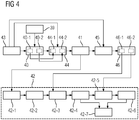
- FIG. 8 shows a flowchart of a second embodiment of a method according to the invention for magnetic resonance imaging in an examination region of an examination subject 15 by means of a magnetic resonance device 11.
- the at least one first shim channel 36 is not set during the acquisition of the magnetic resonance image data in further method step 42 on the basis of the multiple first shim parameter sets determined in further method step 40.
- a third BO field map is calculated using the first BO field map and the second set of shim parameters. It can thereby be taken into account that the modified shim currents in the at least one second shim channel 37 influence the B0 field in the subregions of the examination region.
- this contribution is initially not taken into account.
- the new third BO field map ⁇ B 0 ′′ reproduces at least approximately the field profile after setting the at least one second shim channel 37 (apart from the location-independent term (2 ⁇ / ⁇ ) ⁇ f 0).
- a further method step 46 several adapted first shim parameter sets are determined for the at least one first shim channel 36 using the third BO field map.
- a first sub-step 46-1 of the further method step 46 an adapted first shim parameter set for the first sub-area and in a second sub-step 46-2 of the further method step 46 an adapted second shim parameter set for the second sub-area are determined.
- the result is a new set of shim settings ⁇ f 0 ' (1) , ⁇ G x' (1) , ⁇ G y ' (1) , ⁇ G z ' (1) for the first sub-range or ⁇ f 0 ' (2) , ⁇ G x ' (2) , ⁇ G y ' (2) , ⁇ G z ' (2) for the second sub-area.
- the at least one first shim channel 36 is set on the basis of the plurality of adapted first shim parameter sets.
- the at least one first shim channel 36 is set on the basis of the adapted first shim parameter set for the first sub-range.
- the at least one first shim channel 37 is then set using the adapted second shim parameter set for the second sub-range set.
- adapted first shim parameter sets and adapted second shim parameter sets can also take place iteratively.
- the method steps 45, 46, 44, 41 are carried out in the specified order in an i-th iteration step.
- a B0 ′′ (i) field map is calculated using the first BO field map and the second shim parameter set from the previous iteration step Field map B0 "(i).
- a further BO field map B0 '(i) is calculated for the individual subregions using the B0 ′′ (i) field map calculated in the respective iteration step (step 45) and the adapted first shim parameter sets determined in method step 46
- an adapted second shim parameter set is calculated on the basis of the B0 field map B0 '(i) calculated in method step 41 of the i-th iteration step
- Subrange compared to the adapted first shim parameter set of the (i-1) -th iteration step for the corresponding subrange is smaller than a first set of threshold values specified for the first shim channels and the change in the second shim parameter set calculated in the i-th iteration step compared to that in (i-1) -th step calculated second shim parameter a tz is smaller than a second set of threshold values specified for the second shim channels or when a specified maximum number of iteration steps is exceeded.
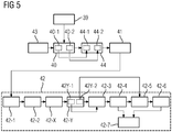
- FIG. 8 shows a flowchart of a third embodiment of a method according to the invention for magnetic resonance imaging in an examination region of an examination subject 15 by means of a magnetic resonance device 11.
- the at least one first shim channel 36 is not set for the sub-area on the basis of the first shim parameter set determined in further method step 40 before the acquisition of the magnetic resonance image data from a sub-area in further method step 42.
- this embodiment also takes into account the influence of the at least one second shim channel 37.
- the field profile is not calculated, but actually measured.
- a fourth BO field map is detected after the setting of the at least one second shim channel 37 in the first sub-step 42-1 of the further method step 42.
- the fourth BO field map is in particular detected at the earliest when the second settling time in the further sub-step 42-2 of the further method step 42 has passed.
- a further sub-step 42-Y of the further method step 42 several changed first shim parameter sets are determined for the at least one first shim channel 36 using the fourth B0 field map.
- a first substep 42Y-1 of substep 42-Y an adapted first shim parameter set for the first sub-area and in a second substep 42Y-2 of substep 42-Y an adapted second shim parameter set for the second sub-area are determined.
- Result is again a center frequency ⁇ f 0 " (1) , and a set of first shim parameter sets ⁇ G x “ (i) , ⁇ G y “ (i) , ⁇ G z “ (i) for the at least one first shim channel 36 for each sub-range.
- the at least one first shim channel 36 is set on the basis of the plurality of adapted first shim parameter sets.
- the at least one first shim channel 36 is set on the basis of the adapted first shim parameter set for the first sub-range.
- the at least one first shim channel 37 is then set on the basis of the adapted second shim parameter set for the second sub-range.
- the acquisition of the first BO field map and / or the fourth B0 field map can take place using raw data which consist of at least three echo signals, which are each acquired after the examination area has been stimulated.
- the computing unit includes the necessary software and / or computer programs that are stored in a storage unit of the computing unit.
- the software and / or computer programs include program means which are designed to execute the respective method when the computer program and / or the software is executed in the computing unit by means of a processor unit of the computing unit.
Landscapes
- Health & Medical Sciences (AREA)
- Physics & Mathematics (AREA)
- Life Sciences & Earth Sciences (AREA)
- Nuclear Medicine, Radiotherapy & Molecular Imaging (AREA)
- General Health & Medical Sciences (AREA)
- Radiology & Medical Imaging (AREA)
- Engineering & Computer Science (AREA)
- High Energy & Nuclear Physics (AREA)
- Condensed Matter Physics & Semiconductors (AREA)
- General Physics & Mathematics (AREA)
- Medical Informatics (AREA)
- Biophysics (AREA)
- Pathology (AREA)
- Biomedical Technology (AREA)
- Heart & Thoracic Surgery (AREA)
- Molecular Biology (AREA)
- Surgery (AREA)
- Animal Behavior & Ethology (AREA)
- Public Health (AREA)
- Veterinary Medicine (AREA)
- Signal Processing (AREA)
- Magnetic Resonance Imaging Apparatus (AREA)
Claims (11)
- Procédé d'imagerie par résonnance magnétique dans une région à examiner d'un objet (15) à examiner au moyen d'un appareil (11) à résonnance magnétique, lequel comporte une unité (35) shim, l'unité (35) shim comportant un premier ensemble de canal shim ayant au moins un premier canal (36) shim et un deuxième ensemble de canal shim ayant au moins un deuxième canal (37) shim, le procédé comportant les étapes suivantes :- on subdivise la région à examiner en plusieurs régions partielles,- on détermine une pluralité de premiers ensembles de paramètres shim pour le au moins un premier canal (36) shim, un premier ensemble de paramètres de canal shim parmi les plusieurs premiers ensembles de paramètres de canal shim étant déterminé pour chacune des plusieurs régions partielles, dans lequel avant la détermination des plusieurs premiers ensembles de paramètres shim, il est obtenu une première carte de champ B0, la détermination des plusieurs premiers ensembles de paramètres shim s'effectuant en utilisant la première carte de champ B0,- on détermine un deuxième ensemble de paramètres shim pour le au moins un deuxième canal (37) shim en prenant en compte les plusieurs premiers ensembles de paramètres shim déterminés,- on acquiert des données d'image par résonnance magnétique de la région à examiner de l'objet (15) à examiner, dans lequel, avant l'acquisition des données d'image par résonnance magnétique on règle le au moins un deuxième canal (37) shim à l'aide du deuxième ensemble de paramètres shim et on règle le au moins un premier canal (36) shim pour l'acquisition des données d'image par résonnance magnétique à partir d'une région partielle déterminée des plusieurs régions partielles à l'aide d'un premier ensemble de paramètres shim déterminé pour la région partielle déterminée, caractérisé en ce que on calcule une deuxième carte de champ B0 en utilisant la première carte de champ B0 et les plusieurs premiers ensembles de paramètres shim, et, lors de la détermination du deuxième ensemble de paramètres shim, ont prend en compte les plusieurs premiers ensembles de paramètres shim de manière à ce que le deuxième ensemble de paramètres shim soit déterminé en utilisant la deuxième carte de champ B0.
- Procédé suivant la revendication 1, dans lequel le premier ensemble de canal shim et le deuxième ensemble de canal shim sont disjoints.
- Procédé suivant l'une des revendications précédentes, dans lequel la deuxième carte de champ B0 est calculée en utilisant la première carte de champ B0 et les plusieurs premiers ensembles de paramètres shim de manière à ce que des valeurs de champ B0, qui sont obtenues à partir des plusieurs premiers ensembles de paramètres shim, soient calculées avec la première carte de champ B0.
- Procédé suivant la revendication 3, dans lequel une section spatiale de la première carte de champ B0 est calculée avec les valeurs de champ B0 qui sont obtenues à partir d'un premier ensemble de paramètres shim appropriés des plusieurs premiers ensembles de paramètres shim, le premier ensemble de paramètres shim appropriés étant déterminé de manière spécifique pour la région partielle des plusieurs régions partielles, qui correspond à la section spatiale.
- Procédé suivant l'une des revendications précédentes, dans lequel une troisièmes carte de champ B0 est calculée en utilisant la première carte de champ B0 et le deuxième ensemble de paramètres shim, une détermination de plusieurs premiers ensembles de paramètres shim adaptés pour le au moins un premier canal (36) shim s'effectuant en utilisant la troisième carte de champ B0, pour l'acquisition des données d'image par résonnance magnétique, le au moins un premier canal (36) shim étant réglé à l'aide des plusieurs premiers ensembles de paramètres shim adaptés.
- Procédé suivant l'une des revendications précédentes, dans lequel pour l'acquisition des données d'image par résonnance magnétique- il est d'abord réglé le au moins un deuxième canal (37) shim à l'aide du deuxième ensemble de paramètres shim,- ensuite le au moins un premier canal (36) shim est réglé à l'aide d'un premier ensemble de paramètres shim, qui est déterminé pour une première région partielle des plusieurs régions partielles,- ensuite des données d'image par résonnance magnétique sont acquises à partir de la première région partielle,- ensuite le au moins un premier canal (36) shim est réglé à l'aide d'un premier ensemble de paramètres shim, qui est déterminé pour une deuxième région partielle des plusieurs régions partielles,- ensuite des données d'image par résonnance magnétique sont acquises à partir de la deuxième région partielle.
- Procédé suivant la revendication 6, dans lequel une deuxième durée transitoire s'écoule entre le réglage du au moins un deuxième canal (37) shim et l'acquisition des données d'image par résonnance magnétique à partir de la première région partielle et une première durée transitoire s'écoule entre le réglage du au moins un premier canal (36) shim à l'aide du premier ensemble de paramètres shim et l'acquisition des données d'image par résonnance magnétique à partir de la première région partielle, la première durée transitoire étant plus courte que la deuxième durée transitoire.
- Procédé suivant l'une des revendications 6 à 7, dans lequel après le réglage du au moins un deuxième canal (37) shim, il est acquis une quatrième carte de champ B0, une détermination de plusieurs premiers ensembles de paramètres shim modifiés s'effectuant pour le au moins un premier canal (36) shim en utilisant la quatrième de champ B0, dans lequel, pendant l'acquisition des données d'image par résonnance magnétique, le au moins un premier canal (36) shim est réglé à l'aide des plusieurs premiers ensembles de paramètres shim modifiés.
- Procédé suivant l'une des revendications précédentes, dans lequel l'acquisition de la première carte de champ B0 s'effectue par utilisation de données brutes, qui sont constituées d'au moins trois signaux d'écho, qui sont respectivement acquis à la suite d'une excitation de la région à examiner.
- Appareil (11) de résonnance magnétique, comportant une unité (35) shim, laquelle comporte un premier ensemble de canal shim comportant au moins un premier canal (36) shim et un deuxième ensemble de canal shim comportant au moins un deuxième canal (37) shim, une unité (32) d'acquisition de données d'image et une unité (24) de calcul comportant une unité (38) de subdivision, une première unité (33) de détermination et une deuxième unité (34) de détermination, l'appareil (11) à résonnance magnétique étant agencé de manière à mettre en œuvre un procédé suivant l'une des revendications précédentes.
- Produit de programme d'ordinateur, qui peut être chargé directement dans une mémoire d'une unité (24) informatique pouvant être programmée d'un appareil (11) à résonnance magnétique, comportant des moyens de codes de programme, afin de mettre en œuvre un procédé suivant l'une des revendications 1 à 9, lorsque le produit de programme d'ordinateur est mis en œuvre dans l'unité (24) informatique de l'appareil (11) à résonnance magnétique suivant la revendication 10.
Applications Claiming Priority (1)
| Application Number | Priority Date | Filing Date | Title |
|---|---|---|---|
| DE102015204953.1A DE102015204953B3 (de) | 2015-03-19 | 2015-03-19 | Verfahren zur Magnetresonanz-Bildgebung |
Publications (3)
| Publication Number | Publication Date |
|---|---|
| EP3078978A2 EP3078978A2 (fr) | 2016-10-12 |
| EP3078978A3 EP3078978A3 (fr) | 2017-01-25 |
| EP3078978B1 true EP3078978B1 (fr) | 2021-10-20 |
Family
ID=55436027
Family Applications (1)
| Application Number | Title | Priority Date | Filing Date |
|---|---|---|---|
| EP16157046.0A Active EP3078978B1 (fr) | 2015-03-19 | 2016-02-24 | Procede d'imagerie par resonance magnetique |
Country Status (5)
| Country | Link |
|---|---|
| US (1) | US9841476B2 (fr) |
| EP (1) | EP3078978B1 (fr) |
| KR (1) | KR101722354B1 (fr) |
| CN (1) | CN105988097B (fr) |
| DE (1) | DE102015204953B3 (fr) |
Families Citing this family (14)
| Publication number | Priority date | Publication date | Assignee | Title |
|---|---|---|---|---|
| US8970217B1 (en) | 2010-04-14 | 2015-03-03 | Hypres, Inc. | System and method for noise reduction in magnetic resonance imaging |
| DE102013216529B4 (de) * | 2013-08-21 | 2019-05-23 | Siemens Healthcare Gmbh | Verfahren insbesondere zur patientenadaptiven B0-Homogenisierung von MR-Systemen unter Verwendung unterschiedlicher Typen von Shim-Spulen |
| DE102014211354A1 (de) * | 2014-06-13 | 2015-12-17 | Siemens Aktiengesellschaft | Verfahren zur Magnetresonanz-Bildgebung |
| DE102015204955B4 (de) * | 2015-03-19 | 2019-05-16 | Siemens Healthcare Gmbh | Verfahren zur Magnetresonanz-Bildgebung |
| DE102015223897A1 (de) * | 2015-12-01 | 2017-06-01 | Siemens Healthcare Gmbh | Verfahren zur Magnetresonanz-Bildgebung |
| DE102015225080A1 (de) * | 2015-12-14 | 2017-06-14 | Siemens Healthcare Gmbh | Verfahren zum Betrieb eines bildgebenden medizinischen Untersuchungsgeräts mit einer Mehrzahl an Teilsystemen |
| EP3460500A1 (fr) * | 2017-09-26 | 2019-03-27 | Siemens Healthcare GmbH | Appareil d'imagerie médicale destiné à l'imagerie et à l'irradiation par résonance magnétique combinées et procédé de détermination de montage des unités de compensation |
| CN108387857B (zh) * | 2017-12-25 | 2020-11-10 | 深圳先进技术研究院 | 一种用于磁共振成像的局部匀场系统及匀场方法 |
| WO2019126934A1 (fr) * | 2017-12-25 | 2019-07-04 | 深圳先进技术研究院 | Système de correction locale et procédé de correction pour l'imagerie par résonance magnétique |
| CN110320485B (zh) * | 2018-03-29 | 2021-09-17 | 西门子(深圳)磁共振有限公司 | 测量梯度延时和一阶场不均匀度的装置、方法及存储介质 |
| EP3640661A1 (fr) * | 2018-10-16 | 2020-04-22 | Siemens Healthcare GmbH | Procédé et appareil de commande pour la compensation active des champs magnétiques induits par courants de foucault dans l'imagerie par résonance magnétique |
| JP7253433B2 (ja) * | 2019-04-19 | 2023-04-06 | 富士フイルムヘルスケア株式会社 | 磁気共鳴イメージング装置及び誤差磁場の補償方法 |
| CN113219389B (zh) * | 2021-05-07 | 2023-04-14 | 上海联影医疗科技股份有限公司 | 磁共振射频模式确定方法、设备及可读存储介质 |
| DE102021210601B3 (de) * | 2021-09-23 | 2022-11-17 | Siemens Healthcare Gmbh | Ermittlung einer Außenkontur bei MR-Bildgebung |
Family Cites Families (15)
| Publication number | Priority date | Publication date | Assignee | Title |
|---|---|---|---|---|
| DE10160075B4 (de) | 2001-12-07 | 2005-11-17 | Siemens Ag | Verfahren zum Betrieb eines bildgebenden medizinischen Diagnosegeräts |
| DE102004026616B4 (de) | 2004-06-01 | 2007-09-20 | Siemens Ag | Verfahren zum Messen eines Untersuchungsbereichs mit einem Magnetresonanzgerät |
| US7999543B2 (en) | 2005-03-23 | 2011-08-16 | Koninklijke Philips Electronics N.V. | MR method for spatially-resolved determination of relaxation parameters |
| US7315168B2 (en) * | 2005-12-08 | 2008-01-01 | Uri Rapoport | Shimming with MRI gradient |
| US7592812B2 (en) * | 2006-04-13 | 2009-09-22 | Kabushiki Kaisha Toshiba | Magnetic resonance imaging apparatus and static magnetic field correction method |
| JP4188387B2 (ja) * | 2006-06-05 | 2008-11-26 | ジーイー・メディカル・システムズ・グローバル・テクノロジー・カンパニー・エルエルシー | 磁気共鳴イメージング装置及びシム値設定方法 |
| DE102006048423A1 (de) * | 2006-10-12 | 2008-04-17 | Siemens Ag | Verfahren zur Ermittlung und Bewertung eines Shimparametersatzes zum Ansteuern einer Shimeinrichtung in einer Magnetresonanzeinrichtung |
| DE102009004896B4 (de) * | 2009-01-16 | 2010-10-28 | Siemens Aktiengesellschaft | Magnetresonanzgerät und Verfahren zur Messung von Feldinhomogenitäten und Einstellung von Shim-Parametern |
| EP2230530A1 (fr) | 2009-03-20 | 2010-09-22 | Koninklijke Philips Electronics N.V. | Bobine de correction tesserale pour un système à résonance magnétique |
| GB2468852A (en) * | 2009-03-23 | 2010-09-29 | Siemens Magnet Technology Ltd | Arrangements and Method for Shimming a Magnetic Field |
| JP5594632B2 (ja) * | 2009-07-03 | 2014-09-24 | 独立行政法人物質・材料研究機構 | 超伝導磁石用シミング装置 |
| CN102109587A (zh) * | 2009-12-29 | 2011-06-29 | 西门子迈迪特(深圳)磁共振有限公司 | 校正磁场均匀性的方法和装置 |
| DE102011005726B4 (de) * | 2011-03-17 | 2012-12-27 | Siemens Aktiengesellschaft | Einstellung von mindestens einem Shimstrom und einer zugehörigen RF-Mittenfrequenz in einem Magnetresonanzgerät während einer verschachtelten Mehrschicht-MR-Messung eines bewegten Untersuchungsobjekts |
| EP2506026A1 (fr) * | 2011-03-29 | 2012-10-03 | Universitätsklinikum Freiburg | Procédé de compensation dynamique de l'hétérogénéité du champ magnétique dans l'imagerie par résonance magnétique |
| JP5943159B2 (ja) * | 2016-01-04 | 2016-06-29 | 株式会社日立製作所 | 磁気共鳴イメージング装置 |
-
2015
- 2015-03-19 DE DE102015204953.1A patent/DE102015204953B3/de active Active
-
2016
- 2016-02-24 EP EP16157046.0A patent/EP3078978B1/fr active Active
- 2016-03-16 CN CN201610150892.2A patent/CN105988097B/zh active Active
- 2016-03-17 KR KR1020160032153A patent/KR101722354B1/ko active IP Right Grant
- 2016-03-18 US US15/074,250 patent/US9841476B2/en active Active
Also Published As
| Publication number | Publication date |
|---|---|
| US20160274202A1 (en) | 2016-09-22 |
| KR20160113025A (ko) | 2016-09-28 |
| CN105988097B (zh) | 2018-06-12 |
| CN105988097A (zh) | 2016-10-05 |
| US9841476B2 (en) | 2017-12-12 |
| KR101722354B1 (ko) | 2017-03-31 |
| DE102015204953B3 (de) | 2016-08-11 |
| EP3078978A2 (fr) | 2016-10-12 |
| EP3078978A3 (fr) | 2017-01-25 |
Similar Documents
| Publication | Publication Date | Title |
|---|---|---|
| EP3078978B1 (fr) | Procede d'imagerie par resonance magnetique | |
| EP2100158B1 (fr) | Procédé d'obtention des courbes d'amplitude et de phase d'impulsions hf en vue d'une excitation spatiale sélective | |
| DE102015204955B4 (de) | Verfahren zur Magnetresonanz-Bildgebung | |
| DE102013205785B4 (de) | Ermittlung einer Magnetresonanzsystem-Ansteuersequenz auf Basis einer reduzierten Anzahl an Feldverteilungskarten | |
| DE102016218955B4 (de) | Optimiertes Magnetresonanz-Schichtmultiplexing-Verfahren | |
| DE102015222833B4 (de) | Verfahren und Vorrichtung zur Ansteuerung eines Magnetresonanzbildgebungssystems zur simultanen Aufnahme von mehreren Teilvolumina | |
| DE102010041212B4 (de) | Kompensation von Echozeit-unabhängigen Phasen- oder Magnitudenanteilen in aufgenommenen MR-Bilddaten | |
| DE102011083406B4 (de) | Verfahren zur Auswahl eines Unterabtastungsschemas für eine MR-Bildgebung, Verfahren zur Magnetresonanz-Bildgebung und Magnetresonanzanlage | |
| DE102014210778A1 (de) | Erzeugung einer Parameterkarte in der Magnetresonanztechnik | |
| DE102015221888B4 (de) | Gleichzeitige MRT-Mehrschichtmessung | |
| DE102013213591B4 (de) | Ermittlung einer B0-Feldkarte mittels Anregungen mit unterschiedlichen Anregungsfeldern | |
| DE102018218471B3 (de) | Verfahren zur Magnetresonanzbildgebung mit Zusatzgradientenpulsen, Magnetresonanzeinrichtung, Computerprogramm und elektronisch lesbarer Datenträger | |
| DE102014219786A1 (de) | Betrieb eines bildgebenden medizinischen Untersuchungsgeräts | |
| DE102014219779A1 (de) | Betrieb eines bildgebenden medizinischen Untersuchungsgeräts mit einer Mehrzahl an Teilsystemen | |
| DE102013218636B3 (de) | Verfahren zur Ermittlung einer B0-Feldkarte mit einer Magnetresonanzeinrichtung und Recheneinrichtung | |
| DE102011078868A1 (de) | Frequenzkalibrierung einer Magnetresonanzanlage unter Verwendung der Spektralinformationen mehrerer Echosignale | |
| DE102017207128B4 (de) | Verfahren zur Aufnahme eines Magnetresonanzdatensatzes, Datenträger sowie Magnetresonanzanlage | |
| DE102016202884B4 (de) | Dynamisches Justierungsverfahren mit mehreren Justierungsparametern | |
| EP3333584B1 (fr) | Optimisation de la détection simultanée de données rm dans des plusieurs éléments de volume ou des tranches | |
| DE102016200629A1 (de) | Verfahren zur Magnetresonanz-Bildgebung | |
| DE102010041659B4 (de) | Erzeugung eines optimierten MR-Bildes eines Untersuchungsobjekts durch Einstrahlen einer mindestens zwei HF-Pulse umfassenden Pulsfolge | |
| DE102014220776B4 (de) | Verfahren zur Magnetresonanz-Bildgebung | |
| DE102014219780B4 (de) | Bestimmung von Zeitfenstern in einer Messsequenz | |
| DE102014204995B4 (de) | Verfahren und Magnetresonanzanlage zur Fettsättigung | |
| DE102015225080A1 (de) | Verfahren zum Betrieb eines bildgebenden medizinischen Untersuchungsgeräts mit einer Mehrzahl an Teilsystemen |
Legal Events
| Date | Code | Title | Description |
|---|---|---|---|
| PUAI | Public reference made under article 153(3) epc to a published international application that has entered the european phase |
Free format text: ORIGINAL CODE: 0009012 |
|
| AK | Designated contracting states |
Kind code of ref document: A2 Designated state(s): AL AT BE BG CH CY CZ DE DK EE ES FI FR GB GR HR HU IE IS IT LI LT LU LV MC MK MT NL NO PL PT RO RS SE SI SK SM TR |
|
| AX | Request for extension of the european patent |
Extension state: BA ME |
|
| PUAL | Search report despatched |
Free format text: ORIGINAL CODE: 0009013 |
|
| RAP1 | Party data changed (applicant data changed or rights of an application transferred) |
Owner name: SIEMENS HEALTHCARE GMBH |
|
| AK | Designated contracting states |
Kind code of ref document: A3 Designated state(s): AL AT BE BG CH CY CZ DE DK EE ES FI FR GB GR HR HU IE IS IT LI LT LU LV MC MK MT NL NO PL PT RO RS SE SI SK SM TR |
|
| AX | Request for extension of the european patent |
Extension state: BA ME |
|
| RIC1 | Information provided on ipc code assigned before grant |
Ipc: G01R 33/54 20060101ALN20161222BHEP Ipc: G01R 33/3875 20060101AFI20161222BHEP |
|
| RIN1 | Information on inventor provided before grant (corrected) |
Inventor name: STEMMER, ALTO |
|
| STAA | Information on the status of an ep patent application or granted ep patent |
Free format text: STATUS: REQUEST FOR EXAMINATION WAS MADE |
|
| 17P | Request for examination filed |
Effective date: 20170619 |
|
| RBV | Designated contracting states (corrected) |
Designated state(s): AL AT BE BG CH CY CZ DE DK EE ES FI FR GB GR HR HU IE IS IT LI LT LU LV MC MK MT NL NO PL PT RO RS SE SI SK SM TR |
|
| GRAP | Despatch of communication of intention to grant a patent |
Free format text: ORIGINAL CODE: EPIDOSNIGR1 |
|
| STAA | Information on the status of an ep patent application or granted ep patent |
Free format text: STATUS: GRANT OF PATENT IS INTENDED |
|
| RIC1 | Information provided on ipc code assigned before grant |
Ipc: G01R 33/54 20060101ALN20210414BHEP Ipc: G01R 33/3875 20060101AFI20210414BHEP |
|
| RIC1 | Information provided on ipc code assigned before grant |
Ipc: G01R 33/54 20060101ALN20210427BHEP Ipc: G01R 33/3875 20060101AFI20210427BHEP |
|
| INTG | Intention to grant announced |
Effective date: 20210517 |
|
| GRAS | Grant fee paid |
Free format text: ORIGINAL CODE: EPIDOSNIGR3 |
|
| GRAA | (expected) grant |
Free format text: ORIGINAL CODE: 0009210 |
|
| STAA | Information on the status of an ep patent application or granted ep patent |
Free format text: STATUS: THE PATENT HAS BEEN GRANTED |
|
| AK | Designated contracting states |
Kind code of ref document: B1 Designated state(s): AL AT BE BG CH CY CZ DE DK EE ES FI FR GB GR HR HU IE IS IT LI LT LU LV MC MK MT NL NO PL PT RO RS SE SI SK SM TR |
|
| REG | Reference to a national code |
Ref country code: GB Ref legal event code: FG4D Free format text: NOT ENGLISH |
|
| REG | Reference to a national code |
Ref country code: CH Ref legal event code: EP |
|
| REG | Reference to a national code |
Ref country code: DE Ref legal event code: R096 Ref document number: 502016014004 Country of ref document: DE |
|
| REG | Reference to a national code |
Ref country code: IE Ref legal event code: FG4D Free format text: LANGUAGE OF EP DOCUMENT: GERMAN |
|
| REG | Reference to a national code |
Ref country code: AT Ref legal event code: REF Ref document number: 1440384 Country of ref document: AT Kind code of ref document: T Effective date: 20211115 |
|
| REG | Reference to a national code |
Ref country code: LT Ref legal event code: MG9D |
|
| REG | Reference to a national code |
Ref country code: NL Ref legal event code: MP Effective date: 20211020 |
|
| PG25 | Lapsed in a contracting state [announced via postgrant information from national office to epo] |
Ref country code: RS Free format text: LAPSE BECAUSE OF FAILURE TO SUBMIT A TRANSLATION OF THE DESCRIPTION OR TO PAY THE FEE WITHIN THE PRESCRIBED TIME-LIMIT Effective date: 20211020 Ref country code: LT Free format text: LAPSE BECAUSE OF FAILURE TO SUBMIT A TRANSLATION OF THE DESCRIPTION OR TO PAY THE FEE WITHIN THE PRESCRIBED TIME-LIMIT Effective date: 20211020 Ref country code: FI Free format text: LAPSE BECAUSE OF FAILURE TO SUBMIT A TRANSLATION OF THE DESCRIPTION OR TO PAY THE FEE WITHIN THE PRESCRIBED TIME-LIMIT Effective date: 20211020 Ref country code: BG Free format text: LAPSE BECAUSE OF FAILURE TO SUBMIT A TRANSLATION OF THE DESCRIPTION OR TO PAY THE FEE WITHIN THE PRESCRIBED TIME-LIMIT Effective date: 20220120 |
|
| PG25 | Lapsed in a contracting state [announced via postgrant information from national office to epo] |
Ref country code: IS Free format text: LAPSE BECAUSE OF FAILURE TO SUBMIT A TRANSLATION OF THE DESCRIPTION OR TO PAY THE FEE WITHIN THE PRESCRIBED TIME-LIMIT Effective date: 20220220 Ref country code: SE Free format text: LAPSE BECAUSE OF FAILURE TO SUBMIT A TRANSLATION OF THE DESCRIPTION OR TO PAY THE FEE WITHIN THE PRESCRIBED TIME-LIMIT Effective date: 20211020 Ref country code: PT Free format text: LAPSE BECAUSE OF FAILURE TO SUBMIT A TRANSLATION OF THE DESCRIPTION OR TO PAY THE FEE WITHIN THE PRESCRIBED TIME-LIMIT Effective date: 20220221 Ref country code: PL Free format text: LAPSE BECAUSE OF FAILURE TO SUBMIT A TRANSLATION OF THE DESCRIPTION OR TO PAY THE FEE WITHIN THE PRESCRIBED TIME-LIMIT Effective date: 20211020 Ref country code: NO Free format text: LAPSE BECAUSE OF FAILURE TO SUBMIT A TRANSLATION OF THE DESCRIPTION OR TO PAY THE FEE WITHIN THE PRESCRIBED TIME-LIMIT Effective date: 20220120 Ref country code: NL Free format text: LAPSE BECAUSE OF FAILURE TO SUBMIT A TRANSLATION OF THE DESCRIPTION OR TO PAY THE FEE WITHIN THE PRESCRIBED TIME-LIMIT Effective date: 20211020 Ref country code: LV Free format text: LAPSE BECAUSE OF FAILURE TO SUBMIT A TRANSLATION OF THE DESCRIPTION OR TO PAY THE FEE WITHIN THE PRESCRIBED TIME-LIMIT Effective date: 20211020 Ref country code: HR Free format text: LAPSE BECAUSE OF FAILURE TO SUBMIT A TRANSLATION OF THE DESCRIPTION OR TO PAY THE FEE WITHIN THE PRESCRIBED TIME-LIMIT Effective date: 20211020 Ref country code: GR Free format text: LAPSE BECAUSE OF FAILURE TO SUBMIT A TRANSLATION OF THE DESCRIPTION OR TO PAY THE FEE WITHIN THE PRESCRIBED TIME-LIMIT Effective date: 20220121 Ref country code: ES Free format text: LAPSE BECAUSE OF FAILURE TO SUBMIT A TRANSLATION OF THE DESCRIPTION OR TO PAY THE FEE WITHIN THE PRESCRIBED TIME-LIMIT Effective date: 20211020 |
|
| REG | Reference to a national code |
Ref country code: DE Ref legal event code: R097 Ref document number: 502016014004 Country of ref document: DE |
|
| PG25 | Lapsed in a contracting state [announced via postgrant information from national office to epo] |
Ref country code: SM Free format text: LAPSE BECAUSE OF FAILURE TO SUBMIT A TRANSLATION OF THE DESCRIPTION OR TO PAY THE FEE WITHIN THE PRESCRIBED TIME-LIMIT Effective date: 20211020 Ref country code: SK Free format text: LAPSE BECAUSE OF FAILURE TO SUBMIT A TRANSLATION OF THE DESCRIPTION OR TO PAY THE FEE WITHIN THE PRESCRIBED TIME-LIMIT Effective date: 20211020 Ref country code: RO Free format text: LAPSE BECAUSE OF FAILURE TO SUBMIT A TRANSLATION OF THE DESCRIPTION OR TO PAY THE FEE WITHIN THE PRESCRIBED TIME-LIMIT Effective date: 20211020 Ref country code: EE Free format text: LAPSE BECAUSE OF FAILURE TO SUBMIT A TRANSLATION OF THE DESCRIPTION OR TO PAY THE FEE WITHIN THE PRESCRIBED TIME-LIMIT Effective date: 20211020 Ref country code: DK Free format text: LAPSE BECAUSE OF FAILURE TO SUBMIT A TRANSLATION OF THE DESCRIPTION OR TO PAY THE FEE WITHIN THE PRESCRIBED TIME-LIMIT Effective date: 20211020 Ref country code: CZ Free format text: LAPSE BECAUSE OF FAILURE TO SUBMIT A TRANSLATION OF THE DESCRIPTION OR TO PAY THE FEE WITHIN THE PRESCRIBED TIME-LIMIT Effective date: 20211020 |
|
| PLBE | No opposition filed within time limit |
Free format text: ORIGINAL CODE: 0009261 |
|
| STAA | Information on the status of an ep patent application or granted ep patent |
Free format text: STATUS: NO OPPOSITION FILED WITHIN TIME LIMIT |
|
| 26N | No opposition filed |
Effective date: 20220721 |
|
| PG25 | Lapsed in a contracting state [announced via postgrant information from national office to epo] |
Ref country code: MC Free format text: LAPSE BECAUSE OF FAILURE TO SUBMIT A TRANSLATION OF THE DESCRIPTION OR TO PAY THE FEE WITHIN THE PRESCRIBED TIME-LIMIT Effective date: 20211020 |
|
| REG | Reference to a national code |
Ref country code: CH Ref legal event code: PL |
|
| REG | Reference to a national code |
Ref country code: BE Ref legal event code: MM Effective date: 20220228 |
|
| PG25 | Lapsed in a contracting state [announced via postgrant information from national office to epo] |
Ref country code: LU Free format text: LAPSE BECAUSE OF NON-PAYMENT OF DUE FEES Effective date: 20220224 Ref country code: AL Free format text: LAPSE BECAUSE OF FAILURE TO SUBMIT A TRANSLATION OF THE DESCRIPTION OR TO PAY THE FEE WITHIN THE PRESCRIBED TIME-LIMIT Effective date: 20211020 |
|
| PG25 | Lapsed in a contracting state [announced via postgrant information from national office to epo] |
Ref country code: SI Free format text: LAPSE BECAUSE OF FAILURE TO SUBMIT A TRANSLATION OF THE DESCRIPTION OR TO PAY THE FEE WITHIN THE PRESCRIBED TIME-LIMIT Effective date: 20211020 |
|
| PG25 | Lapsed in a contracting state [announced via postgrant information from national office to epo] |
Ref country code: LI Free format text: LAPSE BECAUSE OF NON-PAYMENT OF DUE FEES Effective date: 20220228 Ref country code: IE Free format text: LAPSE BECAUSE OF NON-PAYMENT OF DUE FEES Effective date: 20220224 Ref country code: CH Free format text: LAPSE BECAUSE OF NON-PAYMENT OF DUE FEES Effective date: 20220228 |
|
| PG25 | Lapsed in a contracting state [announced via postgrant information from national office to epo] |
Ref country code: BE Free format text: LAPSE BECAUSE OF NON-PAYMENT OF DUE FEES Effective date: 20220228 |
|
| REG | Reference to a national code |
Ref country code: AT Ref legal event code: MM01 Ref document number: 1440384 Country of ref document: AT Kind code of ref document: T Effective date: 20220224 |
|
| PG25 | Lapsed in a contracting state [announced via postgrant information from national office to epo] |
Ref country code: AT Free format text: LAPSE BECAUSE OF NON-PAYMENT OF DUE FEES Effective date: 20220224 |
|
| PGFP | Annual fee paid to national office [announced via postgrant information from national office to epo] |
Ref country code: FR Payment date: 20230221 Year of fee payment: 8 |
|
| PG25 | Lapsed in a contracting state [announced via postgrant information from national office to epo] |
Ref country code: IT Free format text: LAPSE BECAUSE OF FAILURE TO SUBMIT A TRANSLATION OF THE DESCRIPTION OR TO PAY THE FEE WITHIN THE PRESCRIBED TIME-LIMIT Effective date: 20211020 |
|
| PGFP | Annual fee paid to national office [announced via postgrant information from national office to epo] |
Ref country code: DE Payment date: 20220620 Year of fee payment: 8 |
|
| REG | Reference to a national code |
Ref country code: DE Ref legal event code: R081 Ref document number: 502016014004 Country of ref document: DE Owner name: SIEMENS HEALTHINEERS AG, DE Free format text: FORMER OWNER: SIEMENS HEALTHCARE GMBH, MUENCHEN, DE |
|
| PG25 | Lapsed in a contracting state [announced via postgrant information from national office to epo] |
Ref country code: HU Free format text: LAPSE BECAUSE OF FAILURE TO SUBMIT A TRANSLATION OF THE DESCRIPTION OR TO PAY THE FEE WITHIN THE PRESCRIBED TIME-LIMIT; INVALID AB INITIO Effective date: 20160224 |
|
| PG25 | Lapsed in a contracting state [announced via postgrant information from national office to epo] |
Ref country code: MK Free format text: LAPSE BECAUSE OF FAILURE TO SUBMIT A TRANSLATION OF THE DESCRIPTION OR TO PAY THE FEE WITHIN THE PRESCRIBED TIME-LIMIT Effective date: 20211020 Ref country code: CY Free format text: LAPSE BECAUSE OF FAILURE TO SUBMIT A TRANSLATION OF THE DESCRIPTION OR TO PAY THE FEE WITHIN THE PRESCRIBED TIME-LIMIT Effective date: 20211020 |
|
| PGFP | Annual fee paid to national office [announced via postgrant information from national office to epo] |
Ref country code: GB Payment date: 20240304 Year of fee payment: 9 |