EP3078635B1 - Reduzierung von expansionskräften , die durch ammoniakspeichermaterialien erzeugt werden - Google Patents
Reduzierung von expansionskräften , die durch ammoniakspeichermaterialien erzeugt werden Download PDFInfo
- Publication number
- EP3078635B1 EP3078635B1 EP15001018.9A EP15001018A EP3078635B1 EP 3078635 B1 EP3078635 B1 EP 3078635B1 EP 15001018 A EP15001018 A EP 15001018A EP 3078635 B1 EP3078635 B1 EP 3078635B1
- Authority
- EP
- European Patent Office
- Prior art keywords
- mat
- sat
- limit
- ammonia
- saturation
- Prior art date
- Legal status (The legal status is an assumption and is not a legal conclusion. Google has not performed a legal analysis and makes no representation as to the accuracy of the status listed.)
- Not-in-force
Links
Images


Classifications
-
- C—CHEMISTRY; METALLURGY
- C01—INORGANIC CHEMISTRY
- C01C—AMMONIA; CYANOGEN; COMPOUNDS THEREOF
- C01C1/00—Ammonia; Compounds thereof
- C01C1/003—Storage or handling of ammonia
- C01C1/006—Storage or handling of ammonia making use of solid ammonia storage materials, e.g. complex ammine salts
-
- B—PERFORMING OPERATIONS; TRANSPORTING
- B01—PHYSICAL OR CHEMICAL PROCESSES OR APPARATUS IN GENERAL
- B01D—SEPARATION
- B01D53/00—Separation of gases or vapours; Recovering vapours of volatile solvents from gases; Chemical or biological purification of waste gases, e.g. engine exhaust gases, smoke, fumes, flue gases, aerosols
- B01D53/02—Separation of gases or vapours; Recovering vapours of volatile solvents from gases; Chemical or biological purification of waste gases, e.g. engine exhaust gases, smoke, fumes, flue gases, aerosols by adsorption, e.g. preparative gas chromatography
- B01D53/04—Separation of gases or vapours; Recovering vapours of volatile solvents from gases; Chemical or biological purification of waste gases, e.g. engine exhaust gases, smoke, fumes, flue gases, aerosols by adsorption, e.g. preparative gas chromatography with stationary adsorbents
-
- B—PERFORMING OPERATIONS; TRANSPORTING
- B01—PHYSICAL OR CHEMICAL PROCESSES OR APPARATUS IN GENERAL
- B01J—CHEMICAL OR PHYSICAL PROCESSES, e.g. CATALYSIS OR COLLOID CHEMISTRY; THEIR RELEVANT APPARATUS
- B01J20/00—Solid sorbent compositions or filter aid compositions; Sorbents for chromatography; Processes for preparing, regenerating or reactivating thereof
- B01J20/02—Solid sorbent compositions or filter aid compositions; Sorbents for chromatography; Processes for preparing, regenerating or reactivating thereof comprising inorganic material
- B01J20/04—Solid sorbent compositions or filter aid compositions; Sorbents for chromatography; Processes for preparing, regenerating or reactivating thereof comprising inorganic material comprising compounds of alkali metals, alkaline earth metals or magnesium
- B01J20/046—Solid sorbent compositions or filter aid compositions; Sorbents for chromatography; Processes for preparing, regenerating or reactivating thereof comprising inorganic material comprising compounds of alkali metals, alkaline earth metals or magnesium containing halogens, e.g. halides
-
- B—PERFORMING OPERATIONS; TRANSPORTING
- B01—PHYSICAL OR CHEMICAL PROCESSES OR APPARATUS IN GENERAL
- B01J—CHEMICAL OR PHYSICAL PROCESSES, e.g. CATALYSIS OR COLLOID CHEMISTRY; THEIR RELEVANT APPARATUS
- B01J20/00—Solid sorbent compositions or filter aid compositions; Sorbents for chromatography; Processes for preparing, regenerating or reactivating thereof
- B01J20/30—Processes for preparing, regenerating, or reactivating
- B01J20/34—Regenerating or reactivating
- B01J20/3433—Regenerating or reactivating of sorbents or filter aids other than those covered by B01J20/3408 - B01J20/3425
-
- B—PERFORMING OPERATIONS; TRANSPORTING
- B01—PHYSICAL OR CHEMICAL PROCESSES OR APPARATUS IN GENERAL
- B01J—CHEMICAL OR PHYSICAL PROCESSES, e.g. CATALYSIS OR COLLOID CHEMISTRY; THEIR RELEVANT APPARATUS
- B01J20/00—Solid sorbent compositions or filter aid compositions; Sorbents for chromatography; Processes for preparing, regenerating or reactivating thereof
- B01J20/30—Processes for preparing, regenerating, or reactivating
- B01J20/34—Regenerating or reactivating
- B01J20/3491—Regenerating or reactivating by pressure treatment
-
- C—CHEMISTRY; METALLURGY
- C01—INORGANIC CHEMISTRY
- C01C—AMMONIA; CYANOGEN; COMPOUNDS THEREOF
- C01C1/00—Ammonia; Compounds thereof
-
- F—MECHANICAL ENGINEERING; LIGHTING; HEATING; WEAPONS; BLASTING
- F17—STORING OR DISTRIBUTING GASES OR LIQUIDS
- F17C—VESSELS FOR CONTAINING OR STORING COMPRESSED, LIQUEFIED OR SOLIDIFIED GASES; FIXED-CAPACITY GAS-HOLDERS; FILLING VESSELS WITH, OR DISCHARGING FROM VESSELS, COMPRESSED, LIQUEFIED, OR SOLIDIFIED GASES
- F17C11/00—Use of gas-solvents or gas-sorbents in vessels
-
- G—PHYSICS
- G01—MEASURING; TESTING
- G01N—INVESTIGATING OR ANALYSING MATERIALS BY DETERMINING THEIR CHEMICAL OR PHYSICAL PROPERTIES
- G01N3/00—Investigating strength properties of solid materials by application of mechanical stress
Definitions
- the present invention relates to ammonia storage in a solid ammonia storage material and specifically to a method for controlling the magnitude of mechanical forces exerted by a solid ammonia storage material on walls of a container holding the storage material.
- Anhydrous ammonia is a widely used chemical with many applications.
- One example is the use as reductant for selective catalytic reduction (SCR) of NOx in exhaust gas from combustion processes.
- Metal ammine salts are materials capable of reversible ammonia absorption/desorption, which can be used as solid storage medium for ammonia (see e.g. WO 2006/012903 A2 ).
- the material is delivered in metal containers (or so-called cartridges) to be integrated in a specific and well-defined packaging or installation volume on a vehicle and then the ammonia is gradually released for NOx reduction ( EP 2181963 A1 ).
- Metal ammine complexes have been studied in the past years and it has turned out to be a challenging class of material. It requires in some cases additives or internal metal foil structure to get the proper heat transfer and it is a known fact that the salt crystal lattice can expand by e.g. a factor of four when absorbing ammonia.
- WO 2014/023841 A1 describes a unit for storing gas by absorption or adsorption with a storage element having a compressible element in contact with the storage element designed to deform under the action of loads applied by the storage element during phases of storing and releasing gas from storage
- US 2011/0284121 A1 describes a method for saturating or re-saturating ammonia storage capable of reversibly absorbing and desorbing ammonia in one or more storage containers, wherein said material is partly or fully depleted of ammonia.
- US 2013/0209316 A1 describes a method for estimating the degree of saturation of a reversible solid ammonia storage material in a storage unit.
- the method comprises:
- a method (not claimed) of designing a container for accommodating solid ammonia storage material where a process temperature for ammonia saturation/resaturation T SAT and a target density of the storage material, D MAT are fixed, and the outcome of the design method is a container design capable of withstanding a resulting exerted pressure from the material, P MAT , or force F MAT , upon ammonia saturation/resaturation.
- a known relation between D MAT , T SAT , and P MAT , or F MAT is used to establish a value of P MAT , or F MAT , and this value is used for the design of the container such that its mechanical strength measured in terms of a hydraulic-limit parameter P LIMIT , or F LIMIT , under which walls of the container do not undergo plastic deformation, or do not undergo deformation of more than 110%, 120%, 150%, or 200% of a deformation at a yield point of the container walls, is equal to or exceeds the value of P MAT , or F MAT .
- a container filled with a solid ammonia storage material with a storage density, D MAT , capable of desorbing and absorbing/reabsorbing ammonia, has a mechanical strength corresponding to a limit-pressure parameter, P LIMIT , or limit-force parameter F LIMIT , at which pressure, or force, inside the container the container does not undergo plastic deformation, or do not undergo deformation of more than 110%, 120%, 150%, or 200% of a deformation at a yield point of the container walls.
- the storage material in the container is filled with ammonia by a saturation/re-saturation process in which the saturation/resaturation of the storage material is performed with the storage material inside the container at a process temperature, T SAT , fulfilling the condition T SAT ⁇ T SATMIN .
- T SATMIN is a minimum temperature of the saturation/resaturation process where P MAT , or F MAT , exerted by the storage material is kept below the limit for the mechanical strength in terms of P LIMIT , or F LIMIT , of the container.
- a correlation between a temperature for ammonia saturation/resaturation process, T SAT , of an ammonia storage material and the hydraulic pressure, P MAT , or equivalent mechanical force, F MAT , generated by the storage material during saturation/resaturation at said temperature T SAT , is used to influence the level of force or pressure exerted by the storage material by carrying out the saturation/resaturation at a temperature where the resulting pressure, P MAT , or force, F MAT , exerted by the storage material is kept below a limit under which the container does not undergo plastic deformation, or does not undergo deformation of more than 110%, 120%, 150%, or 200% of a deformation at a yield point of the container walls.
- pressure and force are linked in the normal mechanical way; i.e. pressure is force exerted per unit area.
- this aspect is utilized in an innovative and constructive manner to achieve the target of the invention: a method for obtaining a robust, durable product having attractive properties and cost for the customer.
- this aspect is applied to achieve a combination of a durable ammonia storage cartridge with attractive properties and a cost-effective refill process.
- the method comprises reducing expansion forces of solid ammonia storage metal ammine complexes capable of reversibly absorbing and desorbing ammonia when confined in one or more metal containers, wherein said material, when undergoing saturation or resaturation with ammonia, is kept at process conditions that reduces the magnitude of the expansion forces to a level that eliminates or reduces deformation of the metal container itself that encapsulates the material.
- the determination of T SATMIN uses the correlation between T SAT and P MAT , or F MAT , and also includes a correlation with the density of the ammonia storage material D MAT where D MAT is calculated based on the ammonia storage material being fully saturated with ammonia.
- a liquid cooling media is used during saturation/restauration, and there is an upper limit on T SAT , for practical reasons, defined by the boiling point of the cooling media (T CMBP , cooling media boiling point) such that T CMBP ⁇ T SAT ⁇ T SATMIN .
- T CMBP is about 100° C.
- the ammonia storage material is cooled during the saturation/resaturation process by a gaseous cooling media.
- the saturation/resaturation process at the temperature T SAT fulfills the condition T CMBP ⁇ T SAT ⁇ T SATMIN , where T CMBP is an upper limit on the temperature at which the saturation/resaturation process is performed cooled by the gaseous cooling media. For example, also in that case T CMBP may be about 100° C.
- the method is based on a mechanical strength (P LIMIT , F LIMIT ) being derived from official legislation targets, such as the target included in the United Nations standardization document ST/SG/AC.10/C.3/88, 12 December 2013, "Report of the Sub-Committee of Experts on the Transport of Dangerous Goods on its forty-fourth session", Chapter 3.3 , according to which each receptacle containing adsorbed or absorbed ammonia shall be able to withstand the pressure generated at 85° C with a volumetric expansion no greater than 0.1 %, wherein the pressure at a temperature of 85° C is less than 12 bar.
- the ammonia storage container has a mechanical strength which enables the container to withstand the pressure generated by desorbed ammonia at 85° C with a volumetric expansion no greater than 0.1 volume-%.
- P LIMIT or F LIMIT , and subsequently T SATMIN , are determined from:
- the procedure of determining T SATMIN includes an experimental mapping procedure in which experimental data points are obtained to establish an empirical relationship or correlation between the dependent variable P MAT , and the independent variable T SAT .
- the mapping procedure comprises:
- the procedure of determining T SATMIN includes an experimental mapping procedure in which experimental data points are obtained to establish an empirical relationship or correlation between the dependent variable P MAT , or F MAT , and the independent variables T SAT and D MAT .
- the mapping procedure comprises:
- the procedure of determining T SATMIN is done by creating the relationship between P MAT , or F MAT , and T SAT , and optionally D MAT via computer simulations using parameters describing the ammonia storage material, ammonia itself and the material in saturated form. Said parameters describe the state of the material in saturated and unsaturated form, the influence of these parameters as a function of temperature and with input of density of the material the model can estimate or predict the level of the dependant variable, P MAT , (or F MAT ) based on the input variables like density, material parameters and saturation temperature.
- P MAT or F MAT
- Such a computer model can be structured in different ways and an example is to use traditional finite element method (FEM) simulation.
- FEM finite element method
- the ammonia gas pressure, P SAT needs to be at least high enough to give a gradient corresponding to at least 10° C difference relative to the equilibrium temperature of the storage material when exposed to the pressure P SAT .
- the process condition, T SAT , and target density of the storage material, D MAT may initially be fixed, e.g. by existing hardware requirements; the outcome is a container design capable of withstanding the resulting exerted pressure, or force, from the material, P MAT , or F MAT , upon ammonia saturation/resaturation:
- the container for storing a solid ammonia storage material with a storage density, D MAT , capable of desorbing and (re)absorbing ammonia may have a mechanical strength corresponding to a limit-pressure parameter, P LIMIT , or limit-force parameter F LIMIT , at which pressure, or force, inside the container the container does not undergo plastic deformation, or does not undergo deformation of more than 110%, 120%, 150%, or 200% of the deformation at the yield point of the container walls.
- the storage material in the container has been filled with ammonia by a saturation/re-saturation process in which the saturation/resaturation of the storage material has been performed with the storage material inside the container at a process temperature, T SAT , fulfilling the condition T SAT ⁇ T SATMIN , where T SATMIN is the minimum temperature of a saturation/resaturation process where P MAT , or F MAT , exerted by the storage material is kept below the limit for the mechanical strength in terms of P LIMIT , or F LIMIT , of the container.
- the correlation or relation between a temperature for ammonia saturation/resaturation process, T SAT , and - optionally - also the storage density, D MAT , of an ammonia storage material, and the hydraulic pressure, P MAT , or equivalent mechanical force, F MAT , generated by the storage material during saturation/resaturation at said temperature T SAT , is used for the design or manufacture of containers storing a material capable of ammonia absorption, more specifically , to influence the level of force or pressure exerted by the storage material by carrying out the saturation/resaturation at a temperature where the resulting pressure, P MAT , or force, F MAT , exerted by the storage material is kept below a limit under which the container does not undergo plastic deformation, or does not undergo deformation of more than 110%, 120%, 150%, or 200% of the deformation at the yield point of the container walls;.
- the methods described herein are also advantageous for preparing the initial product, i.e. a container/cartridge which is charged with ammonia by in-situ saturation of storage material.
- the present invention enables simplified production of an in-situ saturated cartridge where not-yet-saturated storage material is placed inside the cartridge prior to a first saturation and is saturated for the first time inside the (metal) cartridge shell.
- T SAT The temperature level, is determined by the temperature of the cooling media since the cartridges generate heat when ammonia is absorbing. Choosing different cooling media is possible while still fulfilling the T SATMIN .
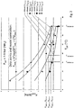
- Fig. 1 shows the material expansion pressure, P MAT , during ammonia saturation plotted against the cooling medium temperature, T SAT , during saturation of a material sample kept in a container capable of monitoring the expansion pressure.
- the mechanical pressure exerted by the material depends strongly on temperature, T SAT .
- the measurements are done for same sample but varying ammonia gas saturation pressures P SAT . This shows that the effect of P MAT is strongly an effect of temperature and not the ammonia gas pressure.
- Fig. 1 shows data points and an empirical correlation (based on the data points) between the temperature T SAT for the ammonia saturation/resaturation process of the storage material, and the hydraulic pressure P MAT (the equivalent mechanical force F MAT could be used in an equivalent manner) generated by the storage material during saturation/resaturation at said temperature T SAT .
- the temperature T SAT at which the saturation/resaturation is performed may be predetermined and fixed.
- the correlation of the type shown in Fig. 1 and described above is used for the design of a cartridge for the solid ammonia storage material capable of withstanding a resulting exerted pressure from the material, P MAT , or force F MAT .
- the relation between T SAT , and P MAT , or F MAT is used to find the value of P MAT , or F MAT , that corresponds to the given value of T SAT .
- P MAT , or F MAT is then used for the design of the cartridge such that the cartridge's mechanical strength measured in terms of a hydraulic-limit parameter P LIMIT , or F LIMIT , under which walls of the cartridge do not undergo plastic deformation, or do not undergo deformation of more than 110%, 120%, 150%, or 200% of the deformation at the yield point of the container walls, is equal to or exceeds the value of P MAT , or F MAT .
- Fig 2 shows data points and a resulting empirical model correlation between P MAT and T SAT similar to Fig. 1 , however for different ammonia-storage-material densities D MAT , with D MAT being a parameter in the representation of P MAT as a function of T SAT of Fig. 2 for four different levels of D MAT , labeled as "A" to "D" (A ⁇ 1.0 g/cm 3 , B ⁇ 1.13 g/cm 3 , C ⁇ 1.25 g/cm 3 and D ⁇ 1.3 g/cm 3 ).
- the ammonia storage material in degassed form is SrCl2, and Sr(NH 3 ) 8 Cl 2 in fully saturated form.
- the density is calculated when the material is in its saturated form. For each density level there is a strong correlation with T SAT .
- Three illustrations, labelled as P LIMIT-1 , P LIMIT-2 , and P LIMIT-3 are made, where a certain P LIMIT-3 is linked to another density D MAT than that of P LIMIT-1 and P LIMIT-2 , and as a result the required saturation temperature, T SATMIN , is located on the X-axis.
- T SAT has to be equal to - or larger - than T SATMIN , i.e. T SAT ⁇ T SATMIN .
- the temperature T SAT at which method is performed may be predetermined and fixed. If one of various available target densities D MAT of ammonia-storage material in the cartridge is also given, the correlation of the type shown in Fig. 2 and described above is used for the design of a cartridge for the solid ammonia storage material capable of withstanding a resulting exerted pressure from the material, P MAT , or force F MAT .
- the relation between T SAT , D MAT , and P MAT , or F MAT is used to find the value of P MAT , or F MAT , that corresponds to the given values of T SAT and D MAT .
- the determined value of P MAT , or F MAT is then used for the design of the cartridge such that the cartridge's mechanical strength measured in terms of a hydraulic-limit parameter P LIMIT , or F LIMIT , under which walls of the cartridge do not undergo plastic deformation, or do not undergo deformation of more than 110%, 120%, 150%, or 200% of the deformation at the yield point of the container walls, is equal to or exceeds the value of P MAT , or F MAT .
- Fig. 3 shows proof of the features of the present invention. Data are shown for cartridges undergoing consecutive cycles of NH 3 -degassing and NH3-resaturation.
- the tested cartridges are cylindrical and made of aluminum.
- the ammonia-storage-material density is approx. 1.13 g/cm 3 in this example, which is supposed to correspond to D MAT-A in Fig. 2 .
- T SATMIN at approx. 38°C.
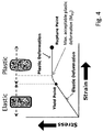
- Figure 4 shows an exemplary illustration of the relationship between strain (deformation) and stress on a metal member, e.g. a container.
- Plastic deformation also referred to as "inelastic deformation”
- the material deforms (strains) because of the stress (created by F MAT , or P MAT ).
- T SAT > T SATMIN the stress created by the material is reduced and the container remains in the area of elastic deformation.
- the relation between stress and strain is nearly linear while in the plastic-deformation regime the strain-stress relation becomes nearly flat (meaning that the material continues to deform even if the stress is not increased).
- the transition between the linear and the flat relation typically has a continuously changing slope; i.e. the change is slope is not abrupt but extends over a finite strain range.
- the "yield point" is defined to be the stress at which a material begins to deform plastically; more specifically, the yield point is typically just before the transition from the linear to the flat part of the relation (when looking into the direction of increasing strain).
- the limit for the mechanical strength of the container in terms of the pressure, P LIMIT , or the force, F LIMIT is defined to be the pressure, or the force, in the container's interior volume under which the walls of container do not undergo plastic deformation; i.e. there is no deformation beyond the yield point.
- a small degree of plastic deformation is acceptable; i.e. a strain beyond the yield point in the transition to the flat plastic-deformation regime before it becomes completely flat.
- the mechanical strength of the container in terms of the pressure, P LIMIT , or the force, F LIMIT is defined to be the pressure, or force, that causes no deformation beyond a point in the transition region of the stress-strain diagram which is referred to as "maximum acceptable plastic deformation", or "M PD ".
- the point M PD is defined as the maximum degree of plastic deformation that is acceptable for a certain container after which is does no longer fit into the physical application for which it is intended.
- M PD in this case at a strain of 200% of the strain at the yield point would be at maximum 1 mm, and the resulting maximum diameter would be 101 mm.
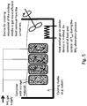
- FIG. 5 shows an example of resaturation of a plurality of containers filled inside with storage ammonia material of the sort described above.
- the storage containers are immersed in a trough filled with cooling media (e.g. cold water), and are thus cooled by the cooling media.
- the temperature of the cooling media is controlled with a suitable device for control of the temperature of the media to reach a targeted saturation temperature T SAT , e.g. a sensor for measuring the cooling-media temperature and a feed-back controller comparing the measured temperature with a target temperature and adjusting the temperature, or the flow, of the cooling media to counteract any difference between the measured and the target temperature.
- T SAT targeted saturation temperature
- Common methods for creating movement of the cooling media to increase heat transfer from the container undergoing saturation can be applied, such as actively creating circulation of the cooling media in the trough by means of a pump or propeller.
- Ammonia is supplied as pressurized gas to the inside of the storage containers.
- Figure 6 shows a diagram of a simulation method to estimate or predict the relationship between T SAT , D MAT and the resulting pressure P MAT (or F MAT ).
- Relevant parameters describing ammonia and the ammonia storage material (with/without ammonia absorbed), referred to as "Thermodynamic input", and independent variables as well as the density, D MAT of the ammonia storage material are fed to a computer model such as a Finite Element Method (FEM) simulation.
- FEM Finite Element Method
- T SATMIN a minimum temperature T SATMIN to be identified of the saturation/resaturation process where P MAT (or F MAT ) exerted by the storage material is kept below the limit for the mechanical strength in terms of P LIMIT , or F LIMIT , of the container.
- EXAMPLE 1 Procedure for determining forces from saturation at various temperatures, and finding a minimum saturation temperature T SATMIN for a given cartridge
- the closed-off reactor was evacuated to remove ambient air and then subjected to a pressure of ammonia gas.
- the uptake of ammonia was followed by weighing the reactor and it was in this way ensured that the SrCl 2 was completely saturated by ammonia.
- the force of the saturating SrCl 2 acting one end of the reactor was measured using a load cell.
- the temperature of the reactor walls were actively controlled using Peltier-elements.
- the reactor was heated and the pressure at the outlet fixed to just above ambient pressure to degas ammonia from the reactor.
- the material was degassed for a fixed time before a pressure of ammonia was applied again to resaturate the material. In this way a sample could be recycled several times and the force measurement could be conducted for several temperature points.
- Suitable ammonia storage materials are CaCl2, BaCl2 or any other metal ammine complex in pure form or as a mixture of salts.
- the typical formula for metal ammine complexes is: M(NH 3 ) X H Y where M is a metal ion, X is the coordination number for ammonia (from 0 up to 8 or even 12 in some salts), H is a halide (e.g. chloride ion) and Y is the number of halide ions in the complex.
- M is a metal ion
- X is the coordination number for ammonia (from 0 up to 8 or even 12 in some salts)
- H is a halide (e.g. chloride ion)
- Y is the number of halide ions in the complex.
- SrCl2 and CaCl2 salts absorb 8 ammonia molecules (Sr(NH 3 ) 8 Cl 2 or Ca(NH 3 ) 8 Cl 2 .
- EXAMPLE 2 Finding a metal wall thickness based on a fixed saturation, temperature, and storage-material density.
- a refill process has been established to refill cartridges at a temperature of 20° C.
- the cartridge is cylindrical, with an outer diameter of 178 mm due to requirements of available space on certain vehicles on the market. It is decided to make the cartridge from a deep-drawn aluminum-alloy casing. After deep-drawing, the aluminum alloy has a yield strength of 170 MPa; the "yield strength", or “yield point” is defined to be the stress at which a material begins to deform plastically. Prior to the yield point the material will deform elastically and will return to its original shape when the applied stress is removed. Once the yield point is passed, some fraction of the deformation will be permanent and non-reversible.
- allowable pressure can be calculated using the ASME code and design by rule method. Given a design temperature, allowable stress (from vessel material), vessel radius (from volume) and wall thickness, the following formulas provide the maximum allowable pressure.
- the allowable pressure based on given vessel material and geometry is calculated for a thin walled deep drawn cylindrical aluminum shell.
- E 1
Landscapes
- Chemical & Material Sciences (AREA)
- Organic Chemistry (AREA)
- Analytical Chemistry (AREA)
- Chemical Kinetics & Catalysis (AREA)
- Inorganic Chemistry (AREA)
- Engineering & Computer Science (AREA)
- General Engineering & Computer Science (AREA)
- Mechanical Engineering (AREA)
- Biochemistry (AREA)
- Pathology (AREA)
- Immunology (AREA)
- General Physics & Mathematics (AREA)
- General Health & Medical Sciences (AREA)
- Physics & Mathematics (AREA)
- General Chemical & Material Sciences (AREA)
- Oil, Petroleum & Natural Gas (AREA)
- Life Sciences & Earth Sciences (AREA)
- Health & Medical Sciences (AREA)
- Filling Or Discharging Of Gas Storage Vessels (AREA)
- Exhaust Gas After Treatment (AREA)
Claims (13)
- Verfahren zum Steuern der Stärke von mechanischen Kräften, die von einem Feststoff-Ammoniak-Speichermaterial auf Wände eines Behälters, der das Speichermaterial innerhalb seines inneren Volumens aufnimmt, ausgeübt werden, wenn das Speichermaterial innerhalb des Speicherbehälters eine Sättigung/erneute Sättigung mit Ammoniak durchläuft, wobei das Verfahren Folgendes umfasst:a. Feststellen eines Grenzwerts für die mechanische Festigkeit des Behälters, ausgedrückt durch einen hydraulischen Druck, im Folgenden PLIMIT, oder eine hydraulische Kraft, im Folgenden FLIMIT, in seinem inneren Volumen, bei dem oder der die Wände des Behälters keine plastische Verformung erfahren oder keine Verformung von mehr als 200% einer Verformung bei einer Fließgrenze der Behälterwände erfahren;b. Verwenden einer Beziehung zwischen:I. einer Temperatur für einen Prozess zur Sättigung/erneuten Sättigung mit Ammoniak des Speichermaterials, im Folgenden TSAT, undII. dem hydraulischen Druck PMAT, oder der entsprechenden mechanischen Kraft FMAT, der oder die vom Speichermaterial während der Sättigung/erneuten Sättigung bei der Temperatur TSAT erzeugt wird,zum Bestimmen einer minimalen Temperatur, im Folgenden TSATMIN, für den Prozess zur Sättigung/erneuten Sättigung, bei der PMAT oder FMAT, der oder die vom Speichermaterial ausgeübt wird, unterhalb des Grenzwerts für die mechanische Festigkeit, ausgedrückt durch PLIMIT oder FLIMIT, des Behälters gehalten wird, indem der Prozess zur Sättigung/erneuten Sättigung bei einer Temperatur TSAT ausgeführt wird, die die Bedingung TSAT ≥ TSATMIN erfüllt, wobei die Beziehung durch einen experimentellen Zuordnungsvorgang ermittelt wird, bei dem experimentelle Datenpunkte erhalten werden, oder durch Computersimulationen.
- Verfahren nach Anspruch 1, wobei das Speichermaterial eine Dichte, im Folgenden DMAT, hat, und wobei bei der Feststellung von TSATMIN, neben der Verwendung der Beziehung zwischen TSAT und PMAT, oder FMAT, auch eine Beziehung zur Dichte DMAT des Speichermaterials berücksichtigt wird, da eine höhere Dichte DMAT im Allgemeinen zu größeren mechanischen Kräften führt, die durch das Feststoff-Ammoniak-Speichermaterial auf die Wände des Behälters ausgeübt werden, wobei DMAT sich auf die Dichte des Ammoniak-Speichermaterials, das vollständig mit Ammoniak gesättigt ist, bezieht.
- Verfahren nach Anspruch 1 oder 2, wobei das Ammoniak-Speichermaterial während des Prozesses zur Sättigung/erneuten Sättigung durch ein flüssiges Kühlungsmedium gekühlt wird, das einen Siedepunkt hat, und wobei der Prozess zur Sättigung/erneuten Sättigung bei der Temperatur TSAT die Bedingung TCMBP ≥ TSAT ≥ TSATMIN erfüllt, wobei TCMBP der Siedepunkt des Kühlungsmediums ist.
- Verfahren nach Anspruch 1 oder 2, wobei das Ammoniak-Speichermaterial während des Prozesses zur Sättigung/erneuten Sättigung durch ein gasförmiges Kühlungsmedium gekühlt wird und wobei der Prozess zur Sättigung/erneuten Sättigung bei der Temperatur TSAT die Bedingung TCMBP ≥ TSAT ≥ TSATMIN erfüllt, wobei TCMBP ein oberer Grenzwert für die Temperatur ist, bei der der Prozess zur Sättigung/erneuten Sättigung gekühlt durch das gasförmige Kühlungsmedium ausgeführt wird.
- Verfahren nach Anspruch 3 oder 4, wobei TCMBP 100°C beträgt.
- Verfahren nach einem der Ansprüche 1 bis 5, wobei der Behälter eine mechanische Festigkeit hat, die es dem Behälter ermöglicht dem Druck standzuhalten, der durch das desorbierte Ammoniak bei 85°C mit einer volumetrischen Ausdehnung von nicht mehr als 0,1 Volumen-% erzeugt wird.
- Verfahren nach Anspruch 6, wobei der durch desorbiertes Ammoniak vom Speichermaterial bei 85°C erzeugte Druck 12 bar beträgt.
- Verfahren nach einem der Ansprüche 2 bis 7, wobei PLIMIT, oder FLIMIT, und anschließend TSATMIN durch Folgendes bestimmt werden:a. ein bestehendes Behälterdesign ist verfügbar,b. aus dem bestehenden Design ist der Wert für PLIMIT, oder FLIMIT, bekannt oder es wird Folgendes verwendet: (i) übliche Verfahren aus dem Maschinenbau, (ii) Messungen des hydraulischen Drucks oder (iii) mechanische Simulationen zum Feststellen der Werte für PLIMIT, oder FLIMIT, undc. Verwenden des bekannten oder festgestellten PLIMIT, oder FLIMIT, zum Feststellen der Ladedichte DMAT und der Bedingung zur Sättigung/erneuten Sättigung TSAT ≥ TSATMIN oder TCMBP ≥ TSAT ≥ TSATMIN, um zu verhindern, dass PMAT, oder FMAT, PLIMIT, oder FLIMIT, übersteigt.
- Verfahren nach einem der Ansprüche 1 bis 8, wobei der Vorgang zum Bestimmen von TSATMIN den experimentellen Zuordnungsvorgang umfasst, bei dem experimentelle Datenpunkte erhalten werden, um empirisch die Beziehung zwischen der abhängigen Variable PMAT und der unabhängigen Variable TSAT herzustellen, wobei der Vorgang Folgendes umfasst:a. Vorbereiten wenigstens einer Probe von Ammoniak-Speichermaterial;b. Ausführen von Experimenten zur Ammoniak-Desorption und erneuten Sättigung in einem Probenbehälter, der dafür eingerichtet ist, PMAT zu messen, der vom Material auf die Wände des Probenbehälters ausgeübt wird, wenn das Material eine Sättigung/erneute Sättigung durchläuft, wobei der Vorgang bei verschiedenen Temperaturwerten TSAT ausgeführt wird;c. Verwenden der experimentellen Datenpunkte, um eine Funktion oder Interpolationsformel PMAT = f(TSAT), oder FMAT = f(TSAT), zu erzeugen.
- Verfahren nach einem der Ansprüche 2 bis 8, wobei der Vorgang zum Bestimmen von TSATMIN den experimentellen Zuordnungsvorgang umfasst, bei dem experimentelle Datenpunkte erhalten werden, um empirisch die Beziehung zwischen der abhängigen Variable PMAT, oder FMAT, und den unabhängigen Variablen TSAT und DMAT herzustellen, wobei der Vorgang Folgendes umfasst:d. Vorbereiten wenigstens einer Probe von Ammoniak-Speichermaterial mit bekannter Dichte DMAT;e. Ausführen von Experimenten zur Ammoniak-Desorption und erneuten Sättigung in einem Probenbehälter, der dafür eingerichtet ist, PMAT zu messen, der vom Material auf die Wände des Probenbehälters ausgeübt wird, wenn das Material eine Sättigung/erneute Sättigung durchläuft, wobei der Vorgang bei verschiedenen Temperaturwerten TSAT ausgeführt wird;f. Verwenden der experimentellen Datenpunkte, um eine Funktion oder Interpolationsformel PMAT = f(TSAT, DMAT), oder FMAT = f(TSAT, DMAT), zu erzeugen, falls Proben mit verschiedenen Dichten DMAT gemessen werden.
- Verfahren nach einem der Ansprüche 1 bis 10, wobei der Vorgang zum Bestimmen von TSATMIN durch das Erzeugen der Beziehung zwischen PMAT, oder FMAT, und TSAT durch Computersimulationen ausgeführt wird, die Parameter verwenden, die das Ammoniak-Speichermaterial, das Ammoniak selber und das Speichermaterial in gesättigter Form beschreiben.
- Verfahren nach einem der Ansprüche 2 bis 10, wobei der Vorgang zum Bestimmen von TSATMIN durch das Erzeugen der Beziehung zwischen PMAT, oder FMAT, und TSAT und DMAT durch Computersimulationen ausgeführt wird, die Parameter verwenden, die das Ammoniak-Speichermaterial, das Ammoniak selber und das Speichermaterial in gesättigter Form beschreiben.
- Verfahren nach einem der Ansprüche 1 bis 12, wobei der Grenzwert für die mechanische Festigkeit des Behälters, ausgedrückt durch den hydraulischen Druck PLIMIT oder die hydraulische Kraft FLIMIT in seinem inneren Volumen, der Grenzwert ist, bei dem die Wände des Behälters keine Verformung von mehr als 110%, 120% oder 150% der Verformung bei der Fließgrenze der Behälterwände erfahren.
Priority Applications (10)
| Application Number | Priority Date | Filing Date | Title |
|---|---|---|---|
| EP15001018.9A EP3078635B1 (de) | 2015-04-09 | 2015-04-09 | Reduzierung von expansionskräften , die durch ammoniakspeichermaterialien erzeugt werden |
| ES15001018T ES2705079T3 (es) | 2015-04-09 | 2015-04-09 | Reducción de las fuerzas de expansión creadas por materiales de almacenamiento de amoníaco |
| CN201510334108.9A CN106195626B (zh) | 2015-04-09 | 2015-06-16 | 氨储存材料作用力控制方法、容器设计制造方法及用途 |
| PCT/EP2016/000573 WO2016162123A1 (en) | 2015-04-09 | 2016-04-07 | Reducing expansion forces created by ammonia storage materials |
| KR1020177032384A KR20170136589A (ko) | 2015-04-09 | 2016-04-07 | 암모니아 저장 물질에 의해 생성된 팽창력의 감소 |
| JP2017552866A JP6703005B2 (ja) | 2015-04-09 | 2016-04-07 | アンモニア貯蔵物質が生じさせる膨張力の減少 |
| BR112017020890-3A BR112017020890A2 (pt) | 2015-04-09 | 2016-04-07 | redução das forças de expansão criadas por materiais de armazenamento de amônia |
| US15/564,530 US20180079652A1 (en) | 2015-04-09 | 2016-04-07 | Method for reducing forces (hot fill/re-fill) |
| RU2017136255A RU2721007C2 (ru) | 2015-04-09 | 2016-04-07 | Снижение сил расширения, создаваемых материалами для хранения аммиака |
| EP16717098.4A EP3280680A1 (de) | 2015-04-09 | 2016-04-07 | Reduzierung von expansionskräften, die durch ammoniakspeichermaterialien erzeugt werden |
Applications Claiming Priority (1)
| Application Number | Priority Date | Filing Date | Title |
|---|---|---|---|
| EP15001018.9A EP3078635B1 (de) | 2015-04-09 | 2015-04-09 | Reduzierung von expansionskräften , die durch ammoniakspeichermaterialien erzeugt werden |
Publications (2)
| Publication Number | Publication Date |
|---|---|
| EP3078635A1 EP3078635A1 (de) | 2016-10-12 |
| EP3078635B1 true EP3078635B1 (de) | 2018-10-31 |
Family
ID=52997799
Family Applications (2)
| Application Number | Title | Priority Date | Filing Date |
|---|---|---|---|
| EP15001018.9A Not-in-force EP3078635B1 (de) | 2015-04-09 | 2015-04-09 | Reduzierung von expansionskräften , die durch ammoniakspeichermaterialien erzeugt werden |
| EP16717098.4A Withdrawn EP3280680A1 (de) | 2015-04-09 | 2016-04-07 | Reduzierung von expansionskräften, die durch ammoniakspeichermaterialien erzeugt werden |
Family Applications After (1)
| Application Number | Title | Priority Date | Filing Date |
|---|---|---|---|
| EP16717098.4A Withdrawn EP3280680A1 (de) | 2015-04-09 | 2016-04-07 | Reduzierung von expansionskräften, die durch ammoniakspeichermaterialien erzeugt werden |
Country Status (9)
| Country | Link |
|---|---|
| US (1) | US20180079652A1 (de) |
| EP (2) | EP3078635B1 (de) |
| JP (1) | JP6703005B2 (de) |
| KR (1) | KR20170136589A (de) |
| CN (1) | CN106195626B (de) |
| BR (1) | BR112017020890A2 (de) |
| ES (1) | ES2705079T3 (de) |
| RU (1) | RU2721007C2 (de) |
| WO (1) | WO2016162123A1 (de) |
Families Citing this family (1)
| Publication number | Priority date | Publication date | Assignee | Title |
|---|---|---|---|---|
| US9914645B2 (en) | 2013-11-07 | 2018-03-13 | Regents Of The University Of Minnesota | Process for making ammonia |
Family Cites Families (13)
| Publication number | Priority date | Publication date | Assignee | Title |
|---|---|---|---|---|
| US7213395B2 (en) * | 2004-07-14 | 2007-05-08 | Eaton Corporation | Hybrid catalyst system for exhaust emissions reduction |
| CN101076495B (zh) * | 2004-08-03 | 2010-06-16 | 氨合物公司 | 存储和输送氨的固体材料 |
| WO2006012903A2 (en) | 2004-08-03 | 2006-02-09 | Amminex A/S | A solid ammonia storage and delivery material |
| JP5305661B2 (ja) * | 2005-02-03 | 2013-10-02 | アムミネクス・エミッションズ・テクノロジー・アー/エス | アンモニアの高密度貯蔵 |
| EP2342001A1 (de) | 2008-09-08 | 2011-07-13 | Amminex A/S | Sättigung von ammoniakspeichermaterialien in behältern |
| EP2181963B1 (de) | 2008-10-06 | 2018-12-12 | Amminex Emissions Technology A/S | Freisetzung von gespeichertem Ammoniak beim Start |
| MX2012003766A (es) * | 2009-09-30 | 2012-06-12 | Amminex As | Estructuras conductoras de calor conectadas en sistemas de almacenamiento de amoniaco solido. |
| EP2361883A1 (de) * | 2010-02-25 | 2011-08-31 | Amminex A/S | Verfahren zur Bestimmung des Sättigungsgrads von Materialien zur Aufbewahrung von festem Ammoniak in Behältern |
| CN101832167B (zh) * | 2010-05-07 | 2012-07-11 | 东风汽车有限公司 | 一种scr催化器中的氨气吸附控制方法 |
| EP2388058A1 (de) * | 2010-05-19 | 2011-11-23 | Amminex A/S | Verfahren und Vorrichtung zur erneuten Sättigung von Ammoniakspeichermaterial in Behältern |
| JP5625627B2 (ja) * | 2010-08-30 | 2014-11-19 | 株式会社豊田中央研究所 | アンモニア吸蔵装置および選択的触媒還元システム |
| EP2522823B1 (de) * | 2011-05-13 | 2014-04-23 | Aaqius & Aaqius S.A. | Vorrichtung zur Messung der Menge eines in einem Behälter enthaltenen Reduktionsmittels, vorzugsweise NH3 |
| WO2014023841A1 (fr) * | 2012-08-09 | 2014-02-13 | Aaqius & Aaqius Sa | Unite de stockage d'ammoniac et structure et systeme associes |
-
2015
- 2015-04-09 EP EP15001018.9A patent/EP3078635B1/de not_active Not-in-force
- 2015-04-09 ES ES15001018T patent/ES2705079T3/es active Active
- 2015-06-16 CN CN201510334108.9A patent/CN106195626B/zh not_active Expired - Fee Related
-
2016
- 2016-04-07 JP JP2017552866A patent/JP6703005B2/ja not_active Expired - Fee Related
- 2016-04-07 EP EP16717098.4A patent/EP3280680A1/de not_active Withdrawn
- 2016-04-07 BR BR112017020890-3A patent/BR112017020890A2/pt not_active Application Discontinuation
- 2016-04-07 RU RU2017136255A patent/RU2721007C2/ru not_active IP Right Cessation
- 2016-04-07 US US15/564,530 patent/US20180079652A1/en not_active Abandoned
- 2016-04-07 WO PCT/EP2016/000573 patent/WO2016162123A1/en not_active Ceased
- 2016-04-07 KR KR1020177032384A patent/KR20170136589A/ko not_active Withdrawn
Non-Patent Citations (1)
| Title |
|---|
| None * |
Also Published As
| Publication number | Publication date |
|---|---|
| JP6703005B2 (ja) | 2020-06-03 |
| RU2017136255A3 (de) | 2019-09-06 |
| WO2016162123A1 (en) | 2016-10-13 |
| RU2017136255A (ru) | 2019-05-13 |
| ES2705079T3 (es) | 2019-03-21 |
| EP3280680A1 (de) | 2018-02-14 |
| KR20170136589A (ko) | 2017-12-11 |
| BR112017020890A2 (pt) | 2018-07-10 |
| CN106195626A (zh) | 2016-12-07 |
| CN106195626B (zh) | 2020-06-26 |
| RU2721007C2 (ru) | 2020-05-15 |
| JP2018518435A (ja) | 2018-07-12 |
| US20180079652A1 (en) | 2018-03-22 |
| EP3078635A1 (de) | 2016-10-12 |
Similar Documents
| Publication | Publication Date | Title |
|---|---|---|
| Nam et al. | Three-dimensional modeling and simulation of hydrogen absorption in metal hydride hydrogen storage vessels | |
| EP2571598B1 (de) | Verfahren zur erneuten sättigung von ammoniakspeichermaterial in behältern | |
| US8834603B2 (en) | Method for determining the degree of saturation of solid ammonia storage materials in containers | |
| Kyoung et al. | Three-dimensional modeling and simulation of hydrogen desorption in metal hydride hydrogen storage vessels | |
| US8551219B2 (en) | Method for storing and delivering ammonia from solid storage materials using a vacuum pump | |
| Visaria et al. | Experimental investigation and theoretical modeling of dehydriding process in high-pressure metal hydride hydrogen storage systems | |
| Marty et al. | Numerical simulation of heat and mass transfer during the absorption of hydrogen in a magnesium hydride | |
| Boukhari et al. | Numerical heat and mass transfer investigation of hydrogen absorption in an annulus-disc reactor | |
| Blinov et al. | Experimental investigations and a simple balance model of a metal hydride reactor | |
| Shkolin et al. | Experimental study and numerical modeling: Methane adsorption in microporous carbon adsorbent over the subcritical and supercritical temperature regions | |
| US8473226B2 (en) | Method of determining the filling level of a solid ammonia storage medium in an ammonia storage container | |
| US20160201854A1 (en) | Device and method for indicating a fill level of a sorption store | |
| Belusko et al. | Effectiveness of direct contact PCM thermal storage with a gas as the heat transfer fluid | |
| Mat et al. | Investigation of three‐dimensional heat and mass transfer in a metal hydride reactor | |
| EP3078635B1 (de) | Reduzierung von expansionskräften , die durch ammoniakspeichermaterialien erzeugt werden | |
| Karabanova et al. | Intrinsic kinetics in local modelling of thermochemical heat storage systems | |
| US20180320574A1 (en) | Method for activating/deactivating a biological catalyst used in a conversion system on board a vehicle | |
| Pourpoint et al. | Performance of thermal enhancement materials in high pressure metal hydride storage systems | |
| Gezerman | Industrial-scale purging of ammonia by using nitrogen before environmental discharge | |
| Silin et al. | A case study of a hydride container performance applying non dimensional parameters | |
| Mathew | Application of multiphase heat transfer for efficient hydrogen | |
| Lahmer et al. | Impact of kinetic reaction models on hydrogen absorption in metal hydride tank modeling | |
| Baetcke et al. | Temperature distribution in a new composite material for hydrogen storage: design study of different cooling concepts | |
| Castrillo et al. | Design of a metal hydride | |
| LESMANA et al. | 4-2-1 Development of Innovative Metal Hydride Container for Hydrogen Storage Based on Triply Periodic Minimal Surface Structure |
Legal Events
| Date | Code | Title | Description |
|---|---|---|---|
| PUAI | Public reference made under article 153(3) epc to a published international application that has entered the european phase |
Free format text: ORIGINAL CODE: 0009012 |
|
| AK | Designated contracting states |
Kind code of ref document: A1 Designated state(s): AL AT BE BG CH CY CZ DE DK EE ES FI FR GB GR HR HU IE IS IT LI LT LU LV MC MK MT NL NO PL PT RO RS SE SI SK SM TR |
|
| AX | Request for extension of the european patent |
Extension state: BA ME |
|
| STAA | Information on the status of an ep patent application or granted ep patent |
Free format text: STATUS: REQUEST FOR EXAMINATION WAS MADE |
|
| 17P | Request for examination filed |
Effective date: 20170412 |
|
| RBV | Designated contracting states (corrected) |
Designated state(s): AL AT BE BG CH CY CZ DE DK EE ES FI FR GB GR HR HU IE IS IT LI LT LU LV MC MK MT NL NO PL PT RO RS SE SI SK SM TR |
|
| GRAP | Despatch of communication of intention to grant a patent |
Free format text: ORIGINAL CODE: EPIDOSNIGR1 |
|
| STAA | Information on the status of an ep patent application or granted ep patent |
Free format text: STATUS: GRANT OF PATENT IS INTENDED |
|
| INTG | Intention to grant announced |
Effective date: 20180426 |
|
| GRAS | Grant fee paid |
Free format text: ORIGINAL CODE: EPIDOSNIGR3 |
|
| GRAJ | Information related to disapproval of communication of intention to grant by the applicant or resumption of examination proceedings by the epo deleted |
Free format text: ORIGINAL CODE: EPIDOSDIGR1 |
|
| GRAL | Information related to payment of fee for publishing/printing deleted |
Free format text: ORIGINAL CODE: EPIDOSDIGR3 |
|
| STAA | Information on the status of an ep patent application or granted ep patent |
Free format text: STATUS: REQUEST FOR EXAMINATION WAS MADE |
|
| GRAR | Information related to intention to grant a patent recorded |
Free format text: ORIGINAL CODE: EPIDOSNIGR71 |
|
| STAA | Information on the status of an ep patent application or granted ep patent |
Free format text: STATUS: GRANT OF PATENT IS INTENDED |
|
| GRAA | (expected) grant |
Free format text: ORIGINAL CODE: 0009210 |
|
| STAA | Information on the status of an ep patent application or granted ep patent |
Free format text: STATUS: THE PATENT HAS BEEN GRANTED |
|
| INTC | Intention to grant announced (deleted) | ||
| AK | Designated contracting states |
Kind code of ref document: B1 Designated state(s): AL AT BE BG CH CY CZ DE DK EE ES FI FR GB GR HR HU IE IS IT LI LT LU LV MC MK MT NL NO PL PT RO RS SE SI SK SM TR |
|
| INTG | Intention to grant announced |
Effective date: 20180924 |
|
| REG | Reference to a national code |
Ref country code: CH Ref legal event code: EP Ref country code: GB Ref legal event code: FG4D |
|
| REG | Reference to a national code |
Ref country code: AT Ref legal event code: REF Ref document number: 1059156 Country of ref document: AT Kind code of ref document: T Effective date: 20181115 |
|
| REG | Reference to a national code |
Ref country code: DE Ref legal event code: R096 Ref document number: 602015018925 Country of ref document: DE |
|
| REG | Reference to a national code |
Ref country code: IE Ref legal event code: FG4D |
|
| REG | Reference to a national code |
Ref country code: NL Ref legal event code: MP Effective date: 20181031 |
|
| REG | Reference to a national code |
Ref country code: LT Ref legal event code: MG4D |
|
| REG | Reference to a national code |
Ref country code: ES Ref legal event code: FG2A Ref document number: 2705079 Country of ref document: ES Kind code of ref document: T3 Effective date: 20190321 |
|
| REG | Reference to a national code |
Ref country code: AT Ref legal event code: MK05 Ref document number: 1059156 Country of ref document: AT Kind code of ref document: T Effective date: 20181031 |
|
| PG25 | Lapsed in a contracting state [announced via postgrant information from national office to epo] |
Ref country code: BG Free format text: LAPSE BECAUSE OF FAILURE TO SUBMIT A TRANSLATION OF THE DESCRIPTION OR TO PAY THE FEE WITHIN THE PRESCRIBED TIME-LIMIT Effective date: 20190131 Ref country code: FI Free format text: LAPSE BECAUSE OF FAILURE TO SUBMIT A TRANSLATION OF THE DESCRIPTION OR TO PAY THE FEE WITHIN THE PRESCRIBED TIME-LIMIT Effective date: 20181031 Ref country code: PL Free format text: LAPSE BECAUSE OF FAILURE TO SUBMIT A TRANSLATION OF THE DESCRIPTION OR TO PAY THE FEE WITHIN THE PRESCRIBED TIME-LIMIT Effective date: 20181031 Ref country code: HR Free format text: LAPSE BECAUSE OF FAILURE TO SUBMIT A TRANSLATION OF THE DESCRIPTION OR TO PAY THE FEE WITHIN THE PRESCRIBED TIME-LIMIT Effective date: 20181031 Ref country code: LV Free format text: LAPSE BECAUSE OF FAILURE TO SUBMIT A TRANSLATION OF THE DESCRIPTION OR TO PAY THE FEE WITHIN THE PRESCRIBED TIME-LIMIT Effective date: 20181031 Ref country code: IS Free format text: LAPSE BECAUSE OF FAILURE TO SUBMIT A TRANSLATION OF THE DESCRIPTION OR TO PAY THE FEE WITHIN THE PRESCRIBED TIME-LIMIT Effective date: 20190228 Ref country code: LT Free format text: LAPSE BECAUSE OF FAILURE TO SUBMIT A TRANSLATION OF THE DESCRIPTION OR TO PAY THE FEE WITHIN THE PRESCRIBED TIME-LIMIT Effective date: 20181031 Ref country code: NO Free format text: LAPSE BECAUSE OF FAILURE TO SUBMIT A TRANSLATION OF THE DESCRIPTION OR TO PAY THE FEE WITHIN THE PRESCRIBED TIME-LIMIT Effective date: 20190131 Ref country code: AT Free format text: LAPSE BECAUSE OF FAILURE TO SUBMIT A TRANSLATION OF THE DESCRIPTION OR TO PAY THE FEE WITHIN THE PRESCRIBED TIME-LIMIT Effective date: 20181031 |
|
| PG25 | Lapsed in a contracting state [announced via postgrant information from national office to epo] |
Ref country code: PT Free format text: LAPSE BECAUSE OF FAILURE TO SUBMIT A TRANSLATION OF THE DESCRIPTION OR TO PAY THE FEE WITHIN THE PRESCRIBED TIME-LIMIT Effective date: 20190301 Ref country code: RS Free format text: LAPSE BECAUSE OF FAILURE TO SUBMIT A TRANSLATION OF THE DESCRIPTION OR TO PAY THE FEE WITHIN THE PRESCRIBED TIME-LIMIT Effective date: 20181031 Ref country code: GR Free format text: LAPSE BECAUSE OF FAILURE TO SUBMIT A TRANSLATION OF THE DESCRIPTION OR TO PAY THE FEE WITHIN THE PRESCRIBED TIME-LIMIT Effective date: 20190201 Ref country code: NL Free format text: LAPSE BECAUSE OF FAILURE TO SUBMIT A TRANSLATION OF THE DESCRIPTION OR TO PAY THE FEE WITHIN THE PRESCRIBED TIME-LIMIT Effective date: 20181031 Ref country code: AL Free format text: LAPSE BECAUSE OF FAILURE TO SUBMIT A TRANSLATION OF THE DESCRIPTION OR TO PAY THE FEE WITHIN THE PRESCRIBED TIME-LIMIT Effective date: 20181031 Ref country code: SE Free format text: LAPSE BECAUSE OF FAILURE TO SUBMIT A TRANSLATION OF THE DESCRIPTION OR TO PAY THE FEE WITHIN THE PRESCRIBED TIME-LIMIT Effective date: 20181031 |
|
| PG25 | Lapsed in a contracting state [announced via postgrant information from national office to epo] |
Ref country code: CZ Free format text: LAPSE BECAUSE OF FAILURE TO SUBMIT A TRANSLATION OF THE DESCRIPTION OR TO PAY THE FEE WITHIN THE PRESCRIBED TIME-LIMIT Effective date: 20181031 Ref country code: DK Free format text: LAPSE BECAUSE OF FAILURE TO SUBMIT A TRANSLATION OF THE DESCRIPTION OR TO PAY THE FEE WITHIN THE PRESCRIBED TIME-LIMIT Effective date: 20181031 |
|
| REG | Reference to a national code |
Ref country code: DE Ref legal event code: R097 Ref document number: 602015018925 Country of ref document: DE |
|
| PG25 | Lapsed in a contracting state [announced via postgrant information from national office to epo] |
Ref country code: SK Free format text: LAPSE BECAUSE OF FAILURE TO SUBMIT A TRANSLATION OF THE DESCRIPTION OR TO PAY THE FEE WITHIN THE PRESCRIBED TIME-LIMIT Effective date: 20181031 Ref country code: RO Free format text: LAPSE BECAUSE OF FAILURE TO SUBMIT A TRANSLATION OF THE DESCRIPTION OR TO PAY THE FEE WITHIN THE PRESCRIBED TIME-LIMIT Effective date: 20181031 Ref country code: SM Free format text: LAPSE BECAUSE OF FAILURE TO SUBMIT A TRANSLATION OF THE DESCRIPTION OR TO PAY THE FEE WITHIN THE PRESCRIBED TIME-LIMIT Effective date: 20181031 Ref country code: EE Free format text: LAPSE BECAUSE OF FAILURE TO SUBMIT A TRANSLATION OF THE DESCRIPTION OR TO PAY THE FEE WITHIN THE PRESCRIBED TIME-LIMIT Effective date: 20181031 |
|
| PLBE | No opposition filed within time limit |
Free format text: ORIGINAL CODE: 0009261 |
|
| STAA | Information on the status of an ep patent application or granted ep patent |
Free format text: STATUS: NO OPPOSITION FILED WITHIN TIME LIMIT |
|
| 26N | No opposition filed |
Effective date: 20190801 |
|
| PG25 | Lapsed in a contracting state [announced via postgrant information from national office to epo] |
Ref country code: SI Free format text: LAPSE BECAUSE OF FAILURE TO SUBMIT A TRANSLATION OF THE DESCRIPTION OR TO PAY THE FEE WITHIN THE PRESCRIBED TIME-LIMIT Effective date: 20181031 |
|
| REG | Reference to a national code |
Ref country code: CH Ref legal event code: PL |
|
| REG | Reference to a national code |
Ref country code: BE Ref legal event code: MM Effective date: 20190430 |
|
| PG25 | Lapsed in a contracting state [announced via postgrant information from national office to epo] |
Ref country code: LU Free format text: LAPSE BECAUSE OF NON-PAYMENT OF DUE FEES Effective date: 20190409 Ref country code: MC Free format text: LAPSE BECAUSE OF FAILURE TO SUBMIT A TRANSLATION OF THE DESCRIPTION OR TO PAY THE FEE WITHIN THE PRESCRIBED TIME-LIMIT Effective date: 20181031 |
|
| PG25 | Lapsed in a contracting state [announced via postgrant information from national office to epo] |
Ref country code: LI Free format text: LAPSE BECAUSE OF NON-PAYMENT OF DUE FEES Effective date: 20190430 Ref country code: CH Free format text: LAPSE BECAUSE OF NON-PAYMENT OF DUE FEES Effective date: 20190430 |
|
| PG25 | Lapsed in a contracting state [announced via postgrant information from national office to epo] |
Ref country code: BE Free format text: LAPSE BECAUSE OF NON-PAYMENT OF DUE FEES Effective date: 20190430 |
|
| PG25 | Lapsed in a contracting state [announced via postgrant information from national office to epo] |
Ref country code: TR Free format text: LAPSE BECAUSE OF FAILURE TO SUBMIT A TRANSLATION OF THE DESCRIPTION OR TO PAY THE FEE WITHIN THE PRESCRIBED TIME-LIMIT Effective date: 20181031 |
|
| PG25 | Lapsed in a contracting state [announced via postgrant information from national office to epo] |
Ref country code: IE Free format text: LAPSE BECAUSE OF NON-PAYMENT OF DUE FEES Effective date: 20190409 |
|
| PGFP | Annual fee paid to national office [announced via postgrant information from national office to epo] |
Ref country code: DE Payment date: 20200429 Year of fee payment: 6 Ref country code: FR Payment date: 20200427 Year of fee payment: 6 Ref country code: ES Payment date: 20200504 Year of fee payment: 6 |
|
| PGFP | Annual fee paid to national office [announced via postgrant information from national office to epo] |
Ref country code: GB Payment date: 20200427 Year of fee payment: 6 Ref country code: IT Payment date: 20200423 Year of fee payment: 6 |
|
| PG25 | Lapsed in a contracting state [announced via postgrant information from national office to epo] |
Ref country code: CY Free format text: LAPSE BECAUSE OF FAILURE TO SUBMIT A TRANSLATION OF THE DESCRIPTION OR TO PAY THE FEE WITHIN THE PRESCRIBED TIME-LIMIT Effective date: 20181031 |
|
| PG25 | Lapsed in a contracting state [announced via postgrant information from national office to epo] |
Ref country code: HU Free format text: LAPSE BECAUSE OF FAILURE TO SUBMIT A TRANSLATION OF THE DESCRIPTION OR TO PAY THE FEE WITHIN THE PRESCRIBED TIME-LIMIT; INVALID AB INITIO Effective date: 20150409 Ref country code: MT Free format text: LAPSE BECAUSE OF FAILURE TO SUBMIT A TRANSLATION OF THE DESCRIPTION OR TO PAY THE FEE WITHIN THE PRESCRIBED TIME-LIMIT Effective date: 20181031 |
|
| REG | Reference to a national code |
Ref country code: DE Ref legal event code: R119 Ref document number: 602015018925 Country of ref document: DE |
|
| GBPC | Gb: european patent ceased through non-payment of renewal fee |
Effective date: 20210409 |
|
| PG25 | Lapsed in a contracting state [announced via postgrant information from national office to epo] |
Ref country code: DE Free format text: LAPSE BECAUSE OF NON-PAYMENT OF DUE FEES Effective date: 20211103 Ref country code: FR Free format text: LAPSE BECAUSE OF NON-PAYMENT OF DUE FEES Effective date: 20210430 Ref country code: GB Free format text: LAPSE BECAUSE OF NON-PAYMENT OF DUE FEES Effective date: 20210409 |
|
| PG25 | Lapsed in a contracting state [announced via postgrant information from national office to epo] |
Ref country code: MK Free format text: LAPSE BECAUSE OF FAILURE TO SUBMIT A TRANSLATION OF THE DESCRIPTION OR TO PAY THE FEE WITHIN THE PRESCRIBED TIME-LIMIT Effective date: 20181031 |
|
| REG | Reference to a national code |
Ref country code: ES Ref legal event code: FD2A Effective date: 20220701 |
|
| PG25 | Lapsed in a contracting state [announced via postgrant information from national office to epo] |
Ref country code: ES Free format text: LAPSE BECAUSE OF NON-PAYMENT OF DUE FEES Effective date: 20210410 |
|
| PG25 | Lapsed in a contracting state [announced via postgrant information from national office to epo] |
Ref country code: IT Free format text: LAPSE BECAUSE OF NON-PAYMENT OF DUE FEES Effective date: 20200409 |
|
| PG25 | Lapsed in a contracting state [announced via postgrant information from national office to epo] |
Ref country code: IT Free format text: LAPSE BECAUSE OF NON-PAYMENT OF DUE FEES Effective date: 20210409 |