US8834603B2 - Method for determining the degree of saturation of solid ammonia storage materials in containers - Google Patents
Method for determining the degree of saturation of solid ammonia storage materials in containers Download PDFInfo
- Publication number
- US8834603B2 US8834603B2 US13/579,375 US201113579375A US8834603B2 US 8834603 B2 US8834603 B2 US 8834603B2 US 201113579375 A US201113579375 A US 201113579375A US 8834603 B2 US8834603 B2 US 8834603B2
- Authority
- US
- United States
- Prior art keywords
- pressure
- storage unit
- ammonia
- target
- saturation
- Prior art date
- Legal status (The legal status is an assumption and is not a legal conclusion. Google has not performed a legal analysis and makes no representation as to the accuracy of the status listed.)
- Expired - Fee Related, expires
Links
Images


Classifications
-
- B—PERFORMING OPERATIONS; TRANSPORTING
- B01—PHYSICAL OR CHEMICAL PROCESSES OR APPARATUS IN GENERAL
- B01D—SEPARATION
- B01D53/00—Separation of gases or vapours; Recovering vapours of volatile solvents from gases; Chemical or biological purification of waste gases, e.g. engine exhaust gases, smoke, fumes, flue gases, aerosols
- B01D53/34—Chemical or biological purification of waste gases
- B01D53/92—Chemical or biological purification of waste gases of engine exhaust gases
- B01D53/94—Chemical or biological purification of waste gases of engine exhaust gases by catalytic processes
- B01D53/9495—Controlling the catalytic process
-
- C—CHEMISTRY; METALLURGY
- C01—INORGANIC CHEMISTRY
- C01C—AMMONIA; CYANOGEN; COMPOUNDS THEREOF
- C01C1/00—Ammonia; Compounds thereof
- C01C1/003—Storage or handling of ammonia
- C01C1/006—Storage or handling of ammonia making use of solid ammonia storage materials, e.g. complex ammine salts
-
- F—MECHANICAL ENGINEERING; LIGHTING; HEATING; WEAPONS; BLASTING
- F01—MACHINES OR ENGINES IN GENERAL; ENGINE PLANTS IN GENERAL; STEAM ENGINES
- F01N—GAS-FLOW SILENCERS OR EXHAUST APPARATUS FOR MACHINES OR ENGINES IN GENERAL; GAS-FLOW SILENCERS OR EXHAUST APPARATUS FOR INTERNAL-COMBUSTION ENGINES
- F01N3/00—Exhaust or silencing apparatus having means for purifying, rendering innocuous, or otherwise treating exhaust
- F01N3/08—Exhaust or silencing apparatus having means for purifying, rendering innocuous, or otherwise treating exhaust for rendering innocuous
- F01N3/10—Exhaust or silencing apparatus having means for purifying, rendering innocuous, or otherwise treating exhaust for rendering innocuous by thermal or catalytic conversion of noxious components of exhaust
- F01N3/18—Exhaust or silencing apparatus having means for purifying, rendering innocuous, or otherwise treating exhaust for rendering innocuous by thermal or catalytic conversion of noxious components of exhaust characterised by methods of operation; Control
- F01N3/20—Exhaust or silencing apparatus having means for purifying, rendering innocuous, or otherwise treating exhaust for rendering innocuous by thermal or catalytic conversion of noxious components of exhaust characterised by methods of operation; Control specially adapted for catalytic conversion
- F01N3/206—Adding periodically or continuously substances to exhaust gases for promoting purification, e.g. catalytic material in liquid form, NOx reducing agents
- F01N3/208—Control of selective catalytic reduction [SCR], e.g. by adjusting the dosing of reducing agent
-
- G—PHYSICS
- G01—MEASURING; TESTING
- G01N—INVESTIGATING OR ANALYSING MATERIALS BY DETERMINING THEIR CHEMICAL OR PHYSICAL PROPERTIES
- G01N7/00—Analysing materials by measuring the pressure or volume of a gas or vapour
- G01N7/14—Analysing materials by measuring the pressure or volume of a gas or vapour by allowing the material to emit a gas or vapour, e.g. water vapour, and measuring a pressure or volume difference
- G01N7/16—Analysing materials by measuring the pressure or volume of a gas or vapour by allowing the material to emit a gas or vapour, e.g. water vapour, and measuring a pressure or volume difference by heating the material
-
- F—MECHANICAL ENGINEERING; LIGHTING; HEATING; WEAPONS; BLASTING
- F01—MACHINES OR ENGINES IN GENERAL; ENGINE PLANTS IN GENERAL; STEAM ENGINES
- F01N—GAS-FLOW SILENCERS OR EXHAUST APPARATUS FOR MACHINES OR ENGINES IN GENERAL; GAS-FLOW SILENCERS OR EXHAUST APPARATUS FOR INTERNAL-COMBUSTION ENGINES
- F01N2610/00—Adding substances to exhaust gases
- F01N2610/02—Adding substances to exhaust gases the substance being ammonia or urea
-
- F—MECHANICAL ENGINEERING; LIGHTING; HEATING; WEAPONS; BLASTING
- F01—MACHINES OR ENGINES IN GENERAL; ENGINE PLANTS IN GENERAL; STEAM ENGINES
- F01N—GAS-FLOW SILENCERS OR EXHAUST APPARATUS FOR MACHINES OR ENGINES IN GENERAL; GAS-FLOW SILENCERS OR EXHAUST APPARATUS FOR INTERNAL-COMBUSTION ENGINES
- F01N2610/00—Adding substances to exhaust gases
- F01N2610/06—Adding substances to exhaust gases the substance being in the gaseous form
-
- F—MECHANICAL ENGINEERING; LIGHTING; HEATING; WEAPONS; BLASTING
- F01—MACHINES OR ENGINES IN GENERAL; ENGINE PLANTS IN GENERAL; STEAM ENGINES
- F01N—GAS-FLOW SILENCERS OR EXHAUST APPARATUS FOR MACHINES OR ENGINES IN GENERAL; GAS-FLOW SILENCERS OR EXHAUST APPARATUS FOR INTERNAL-COMBUSTION ENGINES
- F01N2610/00—Adding substances to exhaust gases
- F01N2610/10—Adding substances to exhaust gases the substance being heated, e.g. by heating tank or supply line of the added substance
-
- F—MECHANICAL ENGINEERING; LIGHTING; HEATING; WEAPONS; BLASTING
- F01—MACHINES OR ENGINES IN GENERAL; ENGINE PLANTS IN GENERAL; STEAM ENGINES
- F01N—GAS-FLOW SILENCERS OR EXHAUST APPARATUS FOR MACHINES OR ENGINES IN GENERAL; GAS-FLOW SILENCERS OR EXHAUST APPARATUS FOR INTERNAL-COMBUSTION ENGINES
- F01N2610/00—Adding substances to exhaust gases
- F01N2610/14—Arrangements for the supply of substances, e.g. conduits
- F01N2610/1406—Storage means for substances, e.g. tanks or reservoirs
-
- F—MECHANICAL ENGINEERING; LIGHTING; HEATING; WEAPONS; BLASTING
- F01—MACHINES OR ENGINES IN GENERAL; ENGINE PLANTS IN GENERAL; STEAM ENGINES
- F01N—GAS-FLOW SILENCERS OR EXHAUST APPARATUS FOR MACHINES OR ENGINES IN GENERAL; GAS-FLOW SILENCERS OR EXHAUST APPARATUS FOR INTERNAL-COMBUSTION ENGINES
- F01N2900/00—Details of electrical control or of the monitoring of the exhaust gas treating apparatus
- F01N2900/04—Methods of control or diagnosing
- F01N2900/0408—Methods of control or diagnosing using a feed-back loop
-
- F—MECHANICAL ENGINEERING; LIGHTING; HEATING; WEAPONS; BLASTING
- F01—MACHINES OR ENGINES IN GENERAL; ENGINE PLANTS IN GENERAL; STEAM ENGINES
- F01N—GAS-FLOW SILENCERS OR EXHAUST APPARATUS FOR MACHINES OR ENGINES IN GENERAL; GAS-FLOW SILENCERS OR EXHAUST APPARATUS FOR INTERNAL-COMBUSTION ENGINES
- F01N2900/00—Details of electrical control or of the monitoring of the exhaust gas treating apparatus
- F01N2900/06—Parameters used for exhaust control or diagnosing
- F01N2900/18—Parameters used for exhaust control or diagnosing said parameters being related to the system for adding a substance into the exhaust
- F01N2900/1806—Properties of reducing agent or dosing system
- F01N2900/1808—Pressure
-
- F—MECHANICAL ENGINEERING; LIGHTING; HEATING; WEAPONS; BLASTING
- F01—MACHINES OR ENGINES IN GENERAL; ENGINE PLANTS IN GENERAL; STEAM ENGINES
- F01N—GAS-FLOW SILENCERS OR EXHAUST APPARATUS FOR MACHINES OR ENGINES IN GENERAL; GAS-FLOW SILENCERS OR EXHAUST APPARATUS FOR INTERNAL-COMBUSTION ENGINES
- F01N2900/00—Details of electrical control or of the monitoring of the exhaust gas treating apparatus
- F01N2900/06—Parameters used for exhaust control or diagnosing
- F01N2900/18—Parameters used for exhaust control or diagnosing said parameters being related to the system for adding a substance into the exhaust
- F01N2900/1806—Properties of reducing agent or dosing system
- F01N2900/1811—Temperature
-
- Y—GENERAL TAGGING OF NEW TECHNOLOGICAL DEVELOPMENTS; GENERAL TAGGING OF CROSS-SECTIONAL TECHNOLOGIES SPANNING OVER SEVERAL SECTIONS OF THE IPC; TECHNICAL SUBJECTS COVERED BY FORMER USPC CROSS-REFERENCE ART COLLECTIONS [XRACs] AND DIGESTS
- Y02—TECHNOLOGIES OR APPLICATIONS FOR MITIGATION OR ADAPTATION AGAINST CLIMATE CHANGE
- Y02A—TECHNOLOGIES FOR ADAPTATION TO CLIMATE CHANGE
- Y02A50/00—TECHNOLOGIES FOR ADAPTATION TO CLIMATE CHANGE in human health protection, e.g. against extreme weather
- Y02A50/20—Air quality improvement or preservation, e.g. vehicle emission control or emission reduction by using catalytic converters
-
- Y—GENERAL TAGGING OF NEW TECHNOLOGICAL DEVELOPMENTS; GENERAL TAGGING OF CROSS-SECTIONAL TECHNOLOGIES SPANNING OVER SEVERAL SECTIONS OF THE IPC; TECHNICAL SUBJECTS COVERED BY FORMER USPC CROSS-REFERENCE ART COLLECTIONS [XRACs] AND DIGESTS
- Y02—TECHNOLOGIES OR APPLICATIONS FOR MITIGATION OR ADAPTATION AGAINST CLIMATE CHANGE
- Y02T—CLIMATE CHANGE MITIGATION TECHNOLOGIES RELATED TO TRANSPORTATION
- Y02T10/00—Road transport of goods or passengers
- Y02T10/10—Internal combustion engine [ICE] based vehicles
- Y02T10/12—Improving ICE efficiencies
Definitions
- This invention relates to the application of solid ammonia storage materials as sources for ammonia in an ammonia consuming process.
- Ammonia is made available from a rechargeable solid storage material by controlled thermal desorption from the solid by means of heating.
- the invention relates to a method whereby an approximate saturation level of the storage material is determined by a procedure during start-up. This enables functionality similar to the filling level of a liquid tank.
- Ammonia is a widely used chemical with many applications.
- One specific application is as reductant for selective catalytic reduction (SCR) of NO x in exhaust gas from combustion processes.
- a storage method involving ad- or absorption of molecular ammonia in a solid can circumvent the safety hazard of anhydrous liquid ammonia and eliminate the problem with decomposition of a liquid reductant.
- Metal ammine salts are ammonia absorbing and desorbing materials, which can be used as solid storage media for ammonia (see, e.g. WO 2006/012903 A2), which in turn, as mentioned above, may be used as the reductant in selective catalytic reduction to reduce NO x emissions.
- ASDS Ammonia Storage and Delivery Systems
- WO 2008/077652 A2 discloses a method and device that allows for rapid availability of ammonia from a solid storage material by having a system with two main functionalities: A small, operational unit heated by e.g. electricity and a larger ammonia storage unit that is used as a source to carry out on-board resaturation of the small unit.
- the method and device can have at least two types of configurations:
- WO 2009/156204 A1 discloses a system similar to WO 2008/077652 A2 but with an added feature that the small storage unit is determined as empty by using pressure measurement and the temperature of the storage unit. However, it is not clear whether such a method works really satisfactory
- the invention relates to a method for determining the saturation level in a solid ammonia storage unit that is used as an ammonia source for an ammonia consuming process, e.g. selective reduction of NO x in a vehicle with an internal combustion process.
- the ammonia is made available from the storage material via thermal desorption by heating the storage unit.
- the method of determining S involves:
- t TARGET and T INIT may be based on a model or an algorithm describing the storage unit, e.g. in the form of expected or experimental mapping data or a look-up table.
- a set of experimental mapping data or look-up table may be generated for a prototype of the storage unit, or even specifically for the individual unit in question.
- Some embodiments have a specific configuration of a storage unit where the heating element is placed inside (or embedded by) the storage material whereby the storage material becomes an insulator towards the surroundings. This also provides improved opportunities reducing the power consumption during operation and to improve the resaturation afterwards because re-absorption in the unit releases heat that has to be dissipated away from the unit. The resaturation is much slower if the heating was done from the outside because insulation outside of the heating would be required but that at the same time would have a negative effect on resaturation.
- a special feature of internal heating is that it has been found that the link between t TARGET and S is more well-defined if the heater is inside the unit because all the energy input is dissipated to the storage material before heat is lost to the surroundings. Thus, the estimation of S can be done with greater accuracy.
- an algorithm may additionally consist of:
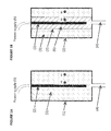
- FIG. 1 shows an example of an embodiment of the invention.
- Parts A and B refer to two different states of saturation: Full saturation (A) and partly saturated (B).
- the legends A 1 , A 2 , B 1 and B 2 refer to certain locations in the storage material.
- FIG. 2 shows an example of an algorithm according to the invention
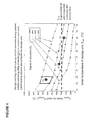
- FIG. 3 shows example of experimental data verifying the capabilities of the invention with Sr(NH 3 ) 8 Cl 2 as the ammonia storage material in the container.
- FIG. 4 shows example of experimental data verifying the capabilities of the invention with Mn(NH 3 ) 6 Cl 2 as the ammonia storage material in the container.
- FIG. 5 shows example of specific start-up profile measurements made and analyzed according to the invention.
- FIG. 6 schematically shows an embodiment of an entire ammonia-providing device or system, according to the invention
- FIG. 1A shows an example of a device where the present inventions is can be applied.
- a storage container 1 which can be made of e.g. steel or aluminum, contains a heating element 2 inside the storage material 3 and the container has an exit tube 4 that allows ammonia to flow out during desorption by heating and it also allows for providing a pressure of ammonia from a different source, e.g. a larger storage container 10 ( FIG. 6 ) to resaturate the storage material.
- the heater can be an electrical heater that has a power supply 5 .
- the pressure measurement is done with a pressure sensor 8 (shown on FIG. 6 ) that is connected to the tube 4 .
- FIG. 1B shows the same unit but here the storage material is partly degassed after some of the ammonia has been desorbed by heating of the unit.
- the degassed part 6 is typically present closest to the heating source and the saturated material 3 is further away from the heating source.
- the line 7 illustrates a front where the material is fully saturated on one side 3 and partly or fully degassed on the other side 6 . In reality, such a sharp front is not present but the overall degree of saturation can be computed as a weighted average over the entire container.
- the storage container 1 makes ammonia available for NOx conversion in a selective catalytic reduction (SCR) catalyst 16 (included in FIG. 6 ) in the exhaust 15 (shown in FIG. 6 ) of a vehicle, e.g. driven by a Diesel engine 14 (shown in FIG. 6 ).
- SCR selective catalytic reduction
- FIG. 1 Two locations in the solid are illustrated: A 1 and B 1 being close to the heater and A 2 and B 2 are far from the heating source. It can be seen that having a temperature sensor either inside the heater, on the wall of the container or as example in points A 1 /B 1 or A 2 /B 2 would not give a well-defined opportunity to link thermodynamics (temperature and pressure relationship of an absorption material) to a degree of saturation. There would always be gradients present in the container during heating and a certain temperature level could not be linked to a well-defined homogeneous temperature of the material providing ammonia pressure by desorption.
- the hypothesis of the invention is that the gradual degassing of the ammonia from a storage unit will increase the heat-transfer distance from a heater to the material that is partly or fully saturated and that this will introduce a well-define time-delay from the time of initiating the heating to the point in time where the moving temperature front reaches the saturated material
- Another hypothesis of the invention is that this time-delay will have a unique relationship also with the initial temperature of the storage unit before the heating starts. Both hypotheses have to be fulfilled in order to make the invention work under all relevant conditions of e.g. a vehicle where the storage unit is used to make ammonia available for NOx conversion by SCR shortly after a cold-start of the vehicle.
- the link to a possible method for estimating the degree of saturation can then be made if the storage unit under almost all combinations of initial temperature, T INIT and degree of saturation, S, has a unique value (or well-defined interval) of the heating time required, t TARGET for reaching a certain desired pressure level, P TARGET .
- This pressure level can be measured by a standard pressure sensor 8 ( FIG. 6 ) and such a sensor would have to be present for such an application of the solid material because of the control of the heating of the unit after the initial warm-up period is over.
- FIG. 2 shows an example of an algorithm structure that can be applied during a start-up procedure.
- S can be estimated based on a model or algorithm that uses the knowledge of the design of the storage unit (e.g. heater power, size, storage material) and/or a calculation relying on (e.g. experimental) mapping data or a look-up table.
- a model or algorithm that uses the knowledge of the design of the storage unit (e.g. heater power, size, storage material) and/or a calculation relying on (e.g. experimental) mapping data or a look-up table.
- the algorithm may additionally use the knowledge of the derived S-value to evaluate if the storage unit requires resaturation from another ammonia source—typically a larger storage unit 10 that is capable of generating ammonia pressure from a storage material 3 by thermal desorption.
- another ammonia source typically a larger storage unit 10 that is capable of generating ammonia pressure from a storage material 3 by thermal desorption.
- FIG. 3 shows one example of experimental data verifying the two-stage hypothesis of the invention.
- a storage unit similar to FIG. 1 has been prepared. It is a stainless steel container 1 of approx. 300 ml in size that contains a electrical heating element 2 inside powered e.g. by a 230 W power supply 5 ( FIG. 6 ) and it contains SrCl 2 6 as the ammonia absorption material directly embedded around the heater 2 and in its fully saturated state it is of the form Sr(NH 3 ) 8 Cl 2 3.
- the unit contains approx. 300 g material in its saturated form 3 .
- the data shows t TARGET to reach P TARGET (3 bar absolute pressure) as a function of T INIT for four different levels of S. T INIT is measured by a standard temperature sensor 9 ( FIG.
- a dosing valve 12 may be provided to dose ammonia e.g. in the exhaust line of a vehicle. During measurement of the raise in pressure, ammonia is preferably not dosed through the dosing valve 12 to ensure that the change in pressure is only a result of heating and not a result of a raise in pressure working against a reduction is pressure caused by dosing.
- FIG. 4 shows another example of experimental data verifying the two-stage hypothesis of the invention—but with a different material: Mn(NH 3 ) 6 Cl 2 . Very well-defined parameter links and narrow standard deviations are found.
- FIGS. 3 and 4 represent experimental data verifying the functionality of the invention, they also represent examples of raw mapping data that can be used in a look-up table. Both FIGS. 3 and 4 give mapping values of S in a two-dimensional space of the input parameters T INIT and t TARGET . Examples of further using the mapping data are:
- the experimental data may be replaced or supplemented by a mathematical model that describes the transient warm-up dynamics of the storage unit by using parameters such as size of unit, heat capacity and heat conductivity of the storage material, the power of the heater and initial temperature to simulate a t TARGET value for different combinations of S and T INIT .
- FIG. 5 shows some examples of the start-up phase under (varying T INIT and S). It can be seen that t TARGET is a function of both S and T INIT —like reported in the extensive mappings of FIGS. 3 and 4 . FIGS. 3 and 4 consist of a vast amount of the t TARGET data based on these types of curves seen on FIG. 5 .
- T INIT can be used with the knowledge of the P-T relationship (e.g. van't Hoff type) for the storage material.
- the controller or algorithm may include a logical structure that chooses to discard an estimation of S when that is made under improper conditions for the applied model/mapping/look-up-table.
- FIG. 2 shows an example of an algorithm structure that can be applied during a start-up procedure.
- knowledge of the initial temperature of the unit, T INIT is established.
- the heating of the unit and start recording the duration of the active heating time t or the accumulated energy Q is initiated.
- the desorption pressure created by the solid storage material undergoing a raise in temperature is—discretely or continuously—measured as a function of time during the heat-up period.
- the time, t TARGET (or alternatively Q TARGET ), is recorded when a given pressure target, P TARGET is reached by the unit.
- the values of t TARGET and T INIT are used to compute an approximate degree of saturation, S.
- the computation may be carried out using a model or an algorithm describing the storage unit, and/or by (experimental or theoretical) mapping data or a look-up table, generated for this type of unit, or specifically for the individual unit considered.
- the sixth block shows an optional activity: If S is below a critical requirement level, the resaturation of the (partly) depleted storage unit in initiated by heating of one or more additional units to obtain a proper driving force for resaturation of the (partly) depleted unit with a too low S-value. Preferably, this method is performed in an heating-up time interval before dosing of ammonia, e.g. into the exhaust line of a vehicle, starts.
- FIG. 3 shows two points, S 1 and S 2 .
- FIG. 4 also shows two points, marked as S 1 and S 2 .
- S can be interpolated to be approx. 70% (using interpolation limits the demand for extensive mapping data or size look-up table).
- S CRIT a critical value of saturation
- S CRIT is not zero but it is a certain lower saturation level (e.g. chosen in the interval 5-95%) that still gives the proper dosing range functionality and start-up performance in a cold start when heating is initiated.
- S CRIT may also be defined as a values that gives a certain desired operating distance (or operating time) of the storage unit.
- FIGS. 3 and 4 show that even a small start-up unit cannot perform according to the required time-to-dose when it is empty—or even close to being empty. It is an advantage of the system to operate in a certain range of saturation degree from 100% saturated and down to e.g. 60% for some units and from 100% and down to e.g. 20% for other units. But when the unit is degassed (S being equal to or very close to 0%), the unit will have an unacceptable start-up time.
- the algorithm or model calculates the amount of ammonia used during operation after the start-up period and then subtracts it from the S-value obtained during the start-up period.
- the algorithm or controller computes that the unit has degassed ammonia corresponding to a decrease in S-value from 100% (S 1 ) to 40% (S 3 )
- the mapping data and/or look-up table and/or mathematical model describing the storage unit takes into account the added heat loss to the surroundings caused by forced convention of heat from the exterior of the storage unit.
- a correction term may include (but not limited to) estimation of heat transfer coefficient and using surface area of the container to estimate a heat loss that may increase the T TARGET value beyond the value obtained if the unit was placed in still air.
- the heat transfer properties and heat capacities are a result of the nature of the solid material, in degassed and saturated form, and not e.g. dominated by gas-phase properties in a highly porous solid or granulated material.
- the average density of the storage material in its saturated in the container form should be at least 50% of its highest theoretical maximum.
- P TARGET may in principle have any value but it is preferred that it is higher than the absolute pressure level where the ammonia has to be dosed and higher than the equilibrium pressure of the storage material at a certain temperature level of the surroundings (e.g. measured at 40° C.).
- P TARGET could be chosen in the range from 1.1 bar to 5 bar and even more suitable a value in the range from 1.5 bar to 3.5 bar.
- P TARGET may also have different values in different intervals.
- T INIT less than 0° C. P TARGET may be different from the requirements of a functional dosing pressure and therefore even be less than 1 bar (the equilibrium pressure may be significantly below 1 bar at the start of heating, e.g. 0.02 bar).
- a higher P TARGET would be required in the look-up table or mapping data because the equilibrium pressure for some storage materials, e.g. SrCl 2 , may already be above 1 bar before start-up heating.
- P TARGET may also be defined as a difference in pressure whereby t TARGET relates to the time of raising the pressure from one level in the transient to another level, e.g. from 0.8 bar to 1.8 bar. That allows accounting for the situation where a storage unit is not completely thermally equilibrated in-between use and therefore has a slightly different response to heating that a unit that has not been operated for several hours.
- the storage material is a metal ammine complex compacted to at least 50% of the theoretical single crystal density of the material.
- SrCl 2 , CaCl 2 , MnCl 2 and MgCl 2 or mixtures thereof are examples of desirable ammonia storage materials in their non-saturated state.
- Other materials such as zeolites or active carbon can be applied.
- FIG. 6 shows an exemplary embodiment of a solid ammonia storage system.
- the invention implemented as a method or device—is particularly advantageous for such a solid ammonia storage system used for reduction of NOx by an SCR catalyst 16 in the exhaust 15 of vehicles powered by combustion engine 14 where the storage system has one or more of the following features:
- flow line(s) 4 temperature sensor 9 , at least one pressure sensor 8 to monitor the pressure during warm-up for determining S in the smaller unit and a dosing valve 12 to control the flow of ammonia once the warm-up period is ended and functional pressure is reached.
Landscapes
- Chemical & Material Sciences (AREA)
- Engineering & Computer Science (AREA)
- Chemical Kinetics & Catalysis (AREA)
- Health & Medical Sciences (AREA)
- Organic Chemistry (AREA)
- Combustion & Propulsion (AREA)
- Analytical Chemistry (AREA)
- Inorganic Chemistry (AREA)
- Mechanical Engineering (AREA)
- General Engineering & Computer Science (AREA)
- Toxicology (AREA)
- Physics & Mathematics (AREA)
- General Health & Medical Sciences (AREA)
- General Chemical & Material Sciences (AREA)
- Oil, Petroleum & Natural Gas (AREA)
- Biomedical Technology (AREA)
- Life Sciences & Earth Sciences (AREA)
- Biochemistry (AREA)
- Environmental & Geological Engineering (AREA)
- General Physics & Mathematics (AREA)
- Immunology (AREA)
- Pathology (AREA)
- Exhaust Gas After Treatment (AREA)
- Investigating Or Analyzing Materials Using Thermal Means (AREA)
- Filling Or Discharging Of Gas Storage Vessels (AREA)
Abstract
Description
-
- if the material in the smaller unit has a higher binding strength for ammonia absorption than the material in the large unit, then the smaller unit can passively absorb ammonia from the big tank after operation—even if the larger unit is not heated.
- If the materials in the two tanks are the same, then the larger tank is equipped with means for heating that provides the opportunity to reach suitable desorption pressure from the main tank to resaturate the smaller unit.
-
- Establish knowledge of the initial temperature of the unit, TINIT. This temperature may simply be the temperature of the surroundings measured elsewhere on the application (vehicle) using the storage unit if the unit has been in non-operating mode for a certain period of time, e.g. 30 minutes or more.
- Initiate the heating of the unit and start recording the duration of the active heating time (e.g. measured in seconds of heating). Alternatively, the active heating time may be accounted for by accumulated energy (e.g. joules or Watt-hours of energy input, Q) if the heater does not have a constant power output at constant voltage supply, such as a PTC heating element.
-
- Record the time, tTARGET (or alternatively QTARGET), when a given pressure target, PTARGET, is reached.
- Use the values of tTARGET and TINIT to compute an approximate degree of saturation, S.
-
- If S is below a critical level, i.e. where it is anticipated that proper start-up time within legislative requirements cannot be achieved on next cold start, the resaturation of the (partly) depleted storage unit is initiated by heating of one or more additional storage units to obtain a proper driving force for resaturation of the (partly) depleted unit with a too low S-value.
- The knowledge of S can be used for on-board diagnostics (OBD) for e.g. automotive industry where there are certain requirements for knowing the operational state of functional hardware related to the emissions control system of a vehicle powered by an internal combustion engine.
-
- During the driving after the start-up period (where tTARGET or QTARGET was measured and S was estimated), the amount of dosed ammonia is computed and subtracted from the estimated S-value to have a real-time parameter for the decreasing degree of saturation. The value of S at the end of the driving period may be compared with the value obtained in the next start-up phase, i.e. that the actual value of S is stored in the model/algorithm/controller.
- During extended driving period, the S-parameter is reduced because of the dosing of ammonia. The controller can determine if a critical level of S is reached during the operation and the additional storage unit requires activation by heating. This prevents the situation that the smaller unit is degassed below a level where suitable start-up times can be obtained on the next cold start.
-
- Creating function that describes S as a continuous surface spline function of TINIT and tTARGET and calculate S for any given combination of TINIT and tTARGET
- Creating interpolation functions that computes S based on the S-values of the nearest measured points of TINIT and tTARGET. As an example, the point S1 on
FIG. 4 gives an approximate S_value of 70% by interpolating between the two nearest measured points with TINIT=40° C. Another example is the point S3 onFIG. 4 where the four nearest points in the box around the point TINIT=−25° C. and tTARGET=650 seconds are used in an interpolation to obtain an approximate level of S=50% - Creating polynomial approximation functions that can compute S based on any combination of the parameters TINIT and tTARGET
-
- a smaller storage unit 1 (e.g. 50 ml to 3 liter in size containing 25 g to 1.5 kg NH3 stored in storage material 3), heated by
electricity 2 through apower supply 5, or other means. - one or more larger
solid storage units 10 with means for heating 2 a through a power supply 5 (e.g. 500 ml to 20 liters containing 400 g to 20 kg NH3 stored instorage material 3 a) capable of storing enough ammonia for a desired service operating interval (e.g. 25000 km).
- a smaller storage unit 1 (e.g. 50 ml to 3 liter in size containing 25 g to 1.5 kg NH3 stored in storage material 3), heated by
-
- a
controller 13 with mapping data, look-up table, models and/or algorithms according to the invention which allows for the estimation of S and the related diagnostics features relying on the knowledge of the value of S and/or using the value of S and SCRIT to determine when the storage unit has to be resaturated by from a different source, e.g. byheating 2 one or more of thelarger storage units 10. - a
valve 11 between the one or morelarger storage units 10 and thesmall unit 1 to avoid backflow of ammonia from apressurized unit 1 to thelarger unit 10 when thelarger unit 10 is not heated and therefore has a lower pressure. Thevalve 11 may be an active valve that is opened by the controller but it may also be a passive valve (check valve or one-way valve). - an engine (e.g. a diesel engine) 14 with an
exhaust line 15 having a selective-catalytic-reduction chamber 16, wherein thedosing valve 12 is in fluid-communicates with theexhaust line 15 so that ammonia can be dosed into theexhaust line 15 downstream of theengine 14 and upstream of theSCR chamber 16 so that it flows in theSCR chamber 16.
- a
-
- does not require any new hardware compared to what is already implemented in the system (storage container, storage material, heater and ammonia gas connection). A temperature sensor is already—in all normal applications—placed somewhere on the system using the storage container. This temperature sensor does not have to be integrated in the storage unit, which lowers the cost of the storage unit.
- works under all required environmental conditions of e.g. vehicles, typically down to as low as −40° C.
- is orientation independent (e.g. unlike liquid level sensing systems) and may include means for taking the convection of air around the vehicle into account.
- establishes the knowledge about when it is necessary to heat an additional, larger storage unit to resaturate the smaller container. Such heating may be done by electricity from the generator of a vehicle and it has a positive influence on the fuel economy if the longest possible interval between such heating instances is obtained while still knowing that the smaller unit can perform according to demands.
Claims (16)
Priority Applications (1)
| Application Number | Priority Date | Filing Date | Title |
|---|---|---|---|
| US13/579,375 US8834603B2 (en) | 2010-02-25 | 2011-02-14 | Method for determining the degree of saturation of solid ammonia storage materials in containers |
Applications Claiming Priority (6)
| Application Number | Priority Date | Filing Date | Title |
|---|---|---|---|
| US30801810P | 2010-02-25 | 2010-02-25 | |
| EP10001955A EP2361883A1 (en) | 2010-02-25 | 2010-02-25 | Method for determining the degree of saturation of solid ammonia storage materials in containers |
| EP10001955 | 2010-02-25 | ||
| EP10001955.3 | 2010-02-25 | ||
| US13/579,375 US8834603B2 (en) | 2010-02-25 | 2011-02-14 | Method for determining the degree of saturation of solid ammonia storage materials in containers |
| PCT/EP2011/000674 WO2011103968A2 (en) | 2010-02-25 | 2011-02-14 | Method for determining the degree of saturation of solid ammonia storage materials in containers |
Publications (2)
| Publication Number | Publication Date |
|---|---|
| US20130209316A1 US20130209316A1 (en) | 2013-08-15 |
| US8834603B2 true US8834603B2 (en) | 2014-09-16 |
Family
ID=42154332
Family Applications (1)
| Application Number | Title | Priority Date | Filing Date |
|---|---|---|---|
| US13/579,375 Expired - Fee Related US8834603B2 (en) | 2010-02-25 | 2011-02-14 | Method for determining the degree of saturation of solid ammonia storage materials in containers |
Country Status (6)
| Country | Link |
|---|---|
| US (1) | US8834603B2 (en) |
| EP (2) | EP2361883A1 (en) |
| JP (1) | JP2013520386A (en) |
| CN (1) | CN102781835A (en) |
| BR (1) | BR112012021076A2 (en) |
| WO (1) | WO2011103968A2 (en) |
Cited By (5)
| Publication number | Priority date | Publication date | Assignee | Title |
|---|---|---|---|---|
| US20130153652A1 (en) * | 2011-03-30 | 2013-06-20 | International Engine Intellectual Property Company , Llc | Status indicator for amonia cartridge |
| US20130263927A1 (en) * | 2007-05-23 | 2013-10-10 | Amminex A/S | Method and device for ammonia storage and delivery using in-situ re-saturation of a delivery unit |
| US20150176460A1 (en) * | 2012-08-09 | 2015-06-25 | Aaqius & Aaqius Sa | System for storing and delivering gaseous ammonia |
| US20150231568A1 (en) * | 2012-08-09 | 2015-08-20 | Aaqius & Aaqius Sa | Gauging the autonomy of a system for storing and delivering gaseous ammonia |
| US20160185611A1 (en) * | 2013-04-12 | 2016-06-30 | Aaqius & Aaqius Sa | Ammonia storage structure and associated systems |
Families Citing this family (21)
| Publication number | Priority date | Publication date | Assignee | Title |
|---|---|---|---|---|
| JP5630411B2 (en) * | 2011-09-26 | 2014-11-26 | 株式会社豊田中央研究所 | Heat recovery type heating device |
| US8820058B2 (en) | 2012-02-02 | 2014-09-02 | Cummins Inc. | System, method, and apparatus for determining solid storage media quality for a NOx reductant |
| FR2987073B1 (en) * | 2012-02-21 | 2014-04-11 | Peugeot Citroen Automobiles Sa | METHOD FOR MANAGING A DEVICE FOR REDUCING NITROGEN OXIDES |
| FR2987075B1 (en) * | 2012-02-22 | 2014-04-11 | Peugeot Citroen Automobiles Sa | METHOD FOR DETERMINING A QUANTITY OF REDUCING AGENT TRANSFERRED TO A STORAGE CARTRIDGE OF A CATALYTIC REDUCTION SYSTEM |
| EP2662128A1 (en) | 2012-05-09 | 2013-11-13 | Inergy Automotive Systems Research (Société Anonyme) | Method and system for purifying the exhaust gases of a combustion engine |
| FR2990994B1 (en) * | 2012-05-22 | 2015-12-04 | Peugeot Citroen Automobiles Sa | METHOD FOR ESTIMATING MASS FLOW RATE OF AN AMMONIA FLOW FOR A CATALYST FOR PROCESSING NITROGEN OXIDES |
| FR2991379B1 (en) * | 2012-06-05 | 2014-07-11 | Peugeot Citroen Automobiles Sa | METHOD FOR ESTIMATING THE LOAD LEVEL OF A RESERVOIR AS A REDUCING AGENT |
| FR2992726B1 (en) * | 2012-06-29 | 2015-05-29 | Inergy Automotive Systems Res | METHOD OF DIAGNOSING A SYSTEM FOR STORING STORED GAS BY SORPTION ON A COMPOUND |
| FR2993603A1 (en) * | 2012-07-20 | 2014-01-24 | Peugeot Citroen Automobiles Sa | Device for determining degree of saturation of reversible storage material in ammonia that is injected into exhaust line of diesel engine in car, has module estimator for estimating value of remaining amount of reducing agent in material |
| FR2993924B1 (en) * | 2012-07-24 | 2014-08-08 | Peugeot Citroen Automobiles Sa | DEVICE FOR GAUGING A REDUCER QUANTITY IN A POLLUTANT REDUCTION SYSTEM |
| WO2014070246A1 (en) * | 2012-11-02 | 2014-05-08 | International Engine Intellectual Property Company, Llc | Ammonia estimation method |
| WO2014070247A1 (en) * | 2012-11-02 | 2014-05-08 | International Engine Intellectual Property Company, Llc | Ammonia estimation method |
| JP6021719B2 (en) * | 2013-04-03 | 2016-11-09 | 株式会社豊田中央研究所 | Ammonia release device |
| FR3004436B1 (en) * | 2013-04-12 | 2016-10-21 | Aaqius & Aaqius Sa | AMMONIA STORAGE STRUCTURE AND ASSOCIATED SYSTEMS |
| CN103410593B (en) * | 2013-07-30 | 2017-03-15 | 中国第一汽车股份有限公司 | The laser detecting method of remaining ammonia amount of solid ammonia storage system |
| US9914645B2 (en) | 2013-11-07 | 2018-03-13 | Regents Of The University Of Minnesota | Process for making ammonia |
| EP3078635B1 (en) * | 2015-04-09 | 2018-10-31 | Amminex Emissions Technology A/S | Reducing expansion forces created by ammonia storage materials |
| CN105675499B (en) * | 2016-02-23 | 2023-05-02 | 吉林大学 | Device for determining reverse reaction crystallization of SCR solid reducing agent |
| CN106640294B (en) * | 2017-01-23 | 2023-02-03 | 中国第一汽车股份有限公司 | Dual-pressure-sensor type gas-drive urea injection system and control method |
| CN113156059B (en) * | 2021-04-20 | 2023-06-09 | 中国电子科技集团公司第四十九研究所 | Preparation method of tubular-structure nano manganese oxide material |
| CN113420186B (en) * | 2021-06-18 | 2022-10-04 | 自然资源部第三地形测量队 | Data storage method, data storage device, computer readable storage medium and data reading method |
Citations (10)
| Publication number | Priority date | Publication date | Assignee | Title |
|---|---|---|---|---|
| US20010053342A1 (en) * | 1997-07-03 | 2001-12-20 | Armin Marko | Method and device for selective catalytic nox reduction |
| WO2006012903A2 (en) | 2004-08-03 | 2006-02-09 | Amminex A/S | A solid ammonia storage and delivery material |
| DE102006061370A1 (en) | 2006-12-22 | 2008-06-26 | Amminex A/S | Storing and supplying ammonia comprises using two storage materials, where one has a higher vapor pressure than the other and serves as an ammonia source for the other when it becomes depleted |
| EP1992397A1 (en) | 2007-05-16 | 2008-11-19 | Amminex A/S | Method and device for safe storage and use of volatile ammonia storage materials |
| WO2009156204A1 (en) | 2008-06-24 | 2009-12-30 | Robert Bosch Gmbh | Exhaust gas after-treatment device for an internal combustion engine |
| US20100021780A1 (en) * | 2007-03-30 | 2010-01-28 | Amminex A/S | System for Storing Ammonia In and Releasing Ammonia from a Stroage Material and Method for Storing and Releasing Ammonia |
| US8088201B2 (en) * | 2006-12-22 | 2012-01-03 | Amminex A/S | Method and device for safe storage and use of volatile ammonia storage materials |
| US8449857B2 (en) * | 2010-05-19 | 2013-05-28 | Amminex A/S | Method for saturating and re-saturating ammonia storage material in containers |
| US8473226B2 (en) * | 2010-09-17 | 2013-06-25 | Amminex A/S | Method of determining the filling level of a solid ammonia storage medium in an ammonia storage container |
| US8551219B2 (en) * | 2009-03-18 | 2013-10-08 | Amminex Emissions Technology A/S | Method for storing and delivering ammonia from solid storage materials using a vacuum pump |
-
2010
- 2010-02-25 EP EP10001955A patent/EP2361883A1/en not_active Withdrawn
-
2011
- 2011-02-14 WO PCT/EP2011/000674 patent/WO2011103968A2/en not_active Ceased
- 2011-02-14 US US13/579,375 patent/US8834603B2/en not_active Expired - Fee Related
- 2011-02-14 CN CN2011800112020A patent/CN102781835A/en active Pending
- 2011-02-14 EP EP11705811.5A patent/EP2539277B1/en not_active Not-in-force
- 2011-02-14 BR BR112012021076A patent/BR112012021076A2/en not_active Application Discontinuation
- 2011-02-14 JP JP2012554242A patent/JP2013520386A/en not_active Withdrawn
Patent Citations (15)
| Publication number | Priority date | Publication date | Assignee | Title |
|---|---|---|---|---|
| US20010053342A1 (en) * | 1997-07-03 | 2001-12-20 | Armin Marko | Method and device for selective catalytic nox reduction |
| WO2006012903A2 (en) | 2004-08-03 | 2006-02-09 | Amminex A/S | A solid ammonia storage and delivery material |
| US8088201B2 (en) * | 2006-12-22 | 2012-01-03 | Amminex A/S | Method and device for safe storage and use of volatile ammonia storage materials |
| DE102006061370A1 (en) | 2006-12-22 | 2008-06-26 | Amminex A/S | Storing and supplying ammonia comprises using two storage materials, where one has a higher vapor pressure than the other and serves as an ammonia source for the other when it becomes depleted |
| WO2008077652A2 (en) | 2006-12-22 | 2008-07-03 | Amminex A/S | Method and device for ammonia storage and delivery using in-situ re-saturation of a delivery unit |
| US20100062296A1 (en) | 2006-12-22 | 2010-03-11 | Amminex A/S | Method and device for ammonia storage and delivery using in situ re-saturation of a delivery unit |
| US20120288774A1 (en) * | 2007-03-30 | 2012-11-15 | Amminex A/S | System for storing ammonia in and releasing ammonia from a storage material and method for storing and releasing ammonia |
| US20100021780A1 (en) * | 2007-03-30 | 2010-01-28 | Amminex A/S | System for Storing Ammonia In and Releasing Ammonia from a Stroage Material and Method for Storing and Releasing Ammonia |
| EP1992397A1 (en) | 2007-05-16 | 2008-11-19 | Amminex A/S | Method and device for safe storage and use of volatile ammonia storage materials |
| DE102008002612A1 (en) | 2008-06-24 | 2009-12-31 | Robert Bosch Gmbh | Exhaust after-treatment device for an internal combustion engine |
| US20110283677A1 (en) | 2008-06-24 | 2011-11-24 | Sebastian Kaefer | Exhaust gas posttreatment device for an internal combustion engine |
| WO2009156204A1 (en) | 2008-06-24 | 2009-12-30 | Robert Bosch Gmbh | Exhaust gas after-treatment device for an internal combustion engine |
| US8551219B2 (en) * | 2009-03-18 | 2013-10-08 | Amminex Emissions Technology A/S | Method for storing and delivering ammonia from solid storage materials using a vacuum pump |
| US8449857B2 (en) * | 2010-05-19 | 2013-05-28 | Amminex A/S | Method for saturating and re-saturating ammonia storage material in containers |
| US8473226B2 (en) * | 2010-09-17 | 2013-06-25 | Amminex A/S | Method of determining the filling level of a solid ammonia storage medium in an ammonia storage container |
Non-Patent Citations (1)
| Title |
|---|
| Johannessen, T., et al., "Ammonia Storage and Delivery Systems for Automotive NOx Aftertreatment", SAE Technical Paper Aeries, Societe of Automotive Engineers, vol. SP-2154, No. 2008-01-1027, Apr. 14, 2008. |
Cited By (9)
| Publication number | Priority date | Publication date | Assignee | Title |
|---|---|---|---|---|
| US20130263927A1 (en) * | 2007-05-23 | 2013-10-10 | Amminex A/S | Method and device for ammonia storage and delivery using in-situ re-saturation of a delivery unit |
| US9400064B2 (en) * | 2007-05-23 | 2016-07-26 | Amminex A/S | Method and device for ammonia storage and delivery using in-situ re-saturation of a delivery unit |
| US20130153652A1 (en) * | 2011-03-30 | 2013-06-20 | International Engine Intellectual Property Company , Llc | Status indicator for amonia cartridge |
| US9322695B2 (en) * | 2011-03-30 | 2016-04-26 | International Engine Intellectual Property Company, Llc. | Status indicator for amonia cartridge |
| US20150176460A1 (en) * | 2012-08-09 | 2015-06-25 | Aaqius & Aaqius Sa | System for storing and delivering gaseous ammonia |
| US20150231568A1 (en) * | 2012-08-09 | 2015-08-20 | Aaqius & Aaqius Sa | Gauging the autonomy of a system for storing and delivering gaseous ammonia |
| US9631536B2 (en) * | 2012-08-09 | 2017-04-25 | Aaqius & Aaqius Sa | System for storing and delivering gaseous ammonia |
| US10315161B2 (en) * | 2012-08-09 | 2019-06-11 | Aaqius & Aaqius Sa | Gauging the autonomy of a system for storing and delivering gaseous ammonia |
| US20160185611A1 (en) * | 2013-04-12 | 2016-06-30 | Aaqius & Aaqius Sa | Ammonia storage structure and associated systems |
Also Published As
| Publication number | Publication date |
|---|---|
| BR112012021076A2 (en) | 2016-05-17 |
| WO2011103968A3 (en) | 2011-11-24 |
| EP2539277A2 (en) | 2013-01-02 |
| JP2013520386A (en) | 2013-06-06 |
| CN102781835A (en) | 2012-11-14 |
| EP2361883A1 (en) | 2011-08-31 |
| US20130209316A1 (en) | 2013-08-15 |
| WO2011103968A2 (en) | 2011-09-01 |
| EP2539277B1 (en) | 2016-12-21 |
Similar Documents
| Publication | Publication Date | Title |
|---|---|---|
| US8834603B2 (en) | Method for determining the degree of saturation of solid ammonia storage materials in containers | |
| EP2366448B1 (en) | Method and device for controlled dosing of a gas with fluctuating supply pressure | |
| US9010091B2 (en) | System for storing ammonia in and releasing ammonia from a storage material and method for storing and releasing ammonia | |
| US8303174B2 (en) | Temperature sensor plausibility diagnosis unit and plausibility diagnosis method and internal combustion engine exhaust purification apparatus | |
| US9032712B2 (en) | Method for heating a delivery system and motor vehicle having a delivery system | |
| CN102016250B (en) | Apparatus, system, and method for reducing NOx emissions on an SCR catalyst | |
| JP4119895B2 (en) | Method for post-processing exhaust gas and apparatus for post-processing exhaust gas | |
| JP5723453B2 (en) | A method for detecting urea deposits in an exhaust line of a vehicle such as an automobile, a method for desorbing urea deposits, and a vehicle such as an automobile adapted to such a method | |
| US8495868B2 (en) | Control strategy for heated fluid lines | |
| CN104583126B (en) | Systems for storage and delivery of gaseous ammonia | |
| US20150160078A1 (en) | Method for diagnosing a system for storing a gas stored by sorption on a compound | |
| CN103732877B (en) | Be used for the method for the amount of the reducing agent of determining storage tank | |
| US10315161B2 (en) | Gauging the autonomy of a system for storing and delivering gaseous ammonia | |
| JP6703005B2 (en) | Reduced expansive force produced by ammonia storage materials | |
| US11668220B2 (en) | Flash boiling injection control | |
| JP2015524534A5 (en) | ||
| WO2014070246A1 (en) | Ammonia estimation method |
Legal Events
| Date | Code | Title | Description |
|---|---|---|---|
| AS | Assignment |
Owner name: AMMINEX A/S, DENMARK Free format text: ASSIGNMENT OF ASSIGNORS INTEREST;ASSIGNORS:JOHANNESSEN, TUE;JOHANSEN, JOHNNY;ZEUTHEN, JACOB HJERRILD;AND OTHERS;REEL/FRAME:029174/0710 Effective date: 20121022 |
|
| AS | Assignment |
Owner name: JYSKE BANK A/S, DENMARK Free format text: SUPPLEMENTAL PATENT SECURITY AGREEMENT;ASSIGNOR:AMMINEX EMISSIONS TECHNOLOGY A/S;REEL/FRAME:029726/0673 Effective date: 20130117 Owner name: AMMINEX EMISSIONS TECHNOLOGY A/S, DENMARK Free format text: ASSIGNMENT OF ASSIGNORS INTEREST;ASSIGNOR:AMMINEX A/S;REEL/FRAME:029726/0653 Effective date: 20130117 |
|
| STCF | Information on status: patent grant |
Free format text: PATENTED CASE |
|
| FEPP | Fee payment procedure |
Free format text: SURCHARGE FOR LATE PAYMENT, LARGE ENTITY (ORIGINAL EVENT CODE: M1554) |
|
| MAFP | Maintenance fee payment |
Free format text: PAYMENT OF MAINTENANCE FEE, 4TH YEAR, LARGE ENTITY (ORIGINAL EVENT CODE: M1551) Year of fee payment: 4 |
|
| FEPP | Fee payment procedure |
Free format text: MAINTENANCE FEE REMINDER MAILED (ORIGINAL EVENT CODE: REM.); ENTITY STATUS OF PATENT OWNER: LARGE ENTITY |
|
| LAPS | Lapse for failure to pay maintenance fees |
Free format text: PATENT EXPIRED FOR FAILURE TO PAY MAINTENANCE FEES (ORIGINAL EVENT CODE: EXP.); ENTITY STATUS OF PATENT OWNER: LARGE ENTITY |
|
| STCH | Information on status: patent discontinuation |
Free format text: PATENT EXPIRED DUE TO NONPAYMENT OF MAINTENANCE FEES UNDER 37 CFR 1.362 |
|
| FP | Lapsed due to failure to pay maintenance fee |
Effective date: 20220916 |