EP3078562A1 - System for detecting when a railway vehicle body structure enters a curve - Google Patents
System for detecting when a railway vehicle body structure enters a curve Download PDFInfo
- Publication number
- EP3078562A1 EP3078562A1 EP16163131.2A EP16163131A EP3078562A1 EP 3078562 A1 EP3078562 A1 EP 3078562A1 EP 16163131 A EP16163131 A EP 16163131A EP 3078562 A1 EP3078562 A1 EP 3078562A1
- Authority
- EP
- European Patent Office
- Prior art keywords
- sensor
- body structure
- axle box
- sensors
- axle
- Prior art date
- Legal status (The legal status is an assumption and is not a legal conclusion. Google has not performed a legal analysis and makes no representation as to the accuracy of the status listed.)
- Withdrawn
Links
Images

Classifications
-
- B—PERFORMING OPERATIONS; TRANSPORTING
- B61—RAILWAYS
- B61F—RAIL VEHICLE SUSPENSIONS, e.g. UNDERFRAMES, BOGIES OR ARRANGEMENTS OF WHEEL AXLES; RAIL VEHICLES FOR USE ON TRACKS OF DIFFERENT WIDTH; PREVENTING DERAILING OF RAIL VEHICLES; WHEEL GUARDS, OBSTRUCTION REMOVERS OR THE LIKE FOR RAIL VEHICLES
- B61F5/00—Constructional details of bogies; Connections between bogies and vehicle underframes; Arrangements or devices for adjusting or allowing self-adjustment of wheel axles or bogies when rounding curves
- B61F5/26—Mounting or securing axle-boxes in vehicle or bogie underframes
- B61F5/30—Axle-boxes mounted for movement under spring control in vehicle or bogie underframes
- B61F5/301—Axle-boxes mounted for movement under spring control in vehicle or bogie underframes incorporating metal springs
- B61F5/302—Leaf springs
-
- B—PERFORMING OPERATIONS; TRANSPORTING
- B61—RAILWAYS
- B61K—AUXILIARY EQUIPMENT SPECIALLY ADAPTED FOR RAILWAYS, NOT OTHERWISE PROVIDED FOR
- B61K3/00—Wetting or lubricating rails or wheel flanges
- B61K3/02—Apparatus therefor combined with vehicles
Definitions
- the invention relates to a railway vehicle body structure equipped with at least one system for detecting the entry curve of said body structure.
- the pivoting of the axle, and therefore the associated curve taking is an information that is very important when, for example, it is desired to control an ancillary system only in the curves. This could be for example a wheel flange lubrication system. It is thus a question of detecting the taking of curve to feed an annexed system.
- the only existing mechanical system for detecting the entry curve of a railway material consists of a system of return rods in which a first rod is mounted on the axis of a bogie, and causes in pivoting a second bead itself driving a sheet in turn, the ends of which are capable of passing from a first inactive position in which one end is in magnetic contact with a magnet secured to the body structure, to a second active position in the end in question is no longer in contact with the magnet, which results in the bogie pivoted relative to the body structure and the rail vehicle is curved.
- the present invention aims at a rail vehicle body structure equipped with at least one system for detecting the entry into curve of said body structure, said detection system being at the same time simple, not bulky and adaptable to a body structure not equipped with bogies.
- the curved entry detection system of a railway vehicle body structure of the invention uses the relative movement between the body structure of a railway vehicle and the axle boxes.
- the detection system provides at least one mechanical sensor integral with the body structure, which adopts an idle free position with respect to the axle box when the body structure travels in a straight line, and an active contact position on the axle box when the body structure enters and circulates.
- the transition from the inactive position to the active position of the sensor is effected by a longitudinal stroke of the axle box relative to the body structure when the latter is in curve, bearing on the sensor.
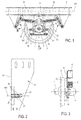
- axles 9 which are, as illustrated on the figure 6 , consisting of an axis 1 at the end of which are two opposite wheels 2,2a each having a non-visible bearing which is housed in an associated axle box 3,4 allowing rotation of the axis relative to a fulcrum.
- the axle box 4 is connected to a leaf spring group 5 which is connected to the body structure 6 by two articulated double-ring systems 7, 8 giving the axle box 4 freedom in rotation relative to to the axis 1 of the axle 9 and a longitudinal freedom along the axis XX 'of advancement of the body structure 6 of 22.5 millimeters or even up to 26.5 millimeters after wear.
- the axle box 4 moves in particular longitudinally relative to the body structure 6 over a maximum distance of 26.5 millimeters from its reference position when the structure of the body cashier 6 is in a straight line.
- the detection system comprises at least one mechanical roller or push sensor 10, or digital sensor, extending along a main contact axis BB ', secured to the body structure 6 and located close and without contact in its position.
- the axle box 4 moves longitudinally along the axes XX 'and BB' until coming into contact with the contactor of the sensor 10. moving it to its active open position.
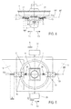
- the detection system comprises two sensors 10,11 located on either side of the axle box 4 in opposite direction and in main contact axis alignment BB 'which is parallel to or coincident with the longitudinal axis XX 'of displacement of the body structure 6.
- Each sensor 10, 11 is attached to a support 18 ( figure 2 ) mounted on a guard plate 12, 13 extending substantially parallel to the wheel 2 located nearby ( figure 3 ), whose upper end 14,15 is secured to the body structure 6 and the lower end 16,17 extends substantially below the axle box 4.
- the position of the sensors 10,11 on the plate of associated guard 12,13 is such that the sensors 10,11 are arranged opposite the axle box 4.
- each sensor 10, 11 is mounted on the support 18 which is flush with the edge 19 of the guard plate 13 located on the side of the axle box 4.
- the support 18 is mounted to move in translation along the main contact axis BB 10 of the sensor 10 not visible in this figure, by means of oblong slots 20 formed on the guard plate 13 and in which can be slid head retaining screws of the support 18 to the guard plate 13.
- a stop 21 is by elsewhere welded to the guard plate 13 near the end of the support 18 which is opposite the edge 19, the distance between this end of the support 18 and the stop 21 being greater than the length of the oblong slots 20, so that the support 18 does not come against the stop 21 before having finished its race in said oblong slots 20.
- each sensor 10, 11 is mounted on a double return spring 22, 23 which is integral with the corresponding stop 21, 21 a. It should also be noted that each sensor 10, 11 is of the spring-return sensor type and thus also intrinsically comprises a return spring 122, 123 ( figure 5 ). Due to the presence of the double external return springs 22, 23, the return springs 122, 123 are mounted inside said sensors 10, 11 or could be alternately mounted outside the sensors 10, 11 but on the side of the associated contactor 25,26.
- the flexibility of the external return springs 22, 23 is less than the flexibility of the internal return springs 122, 123 so that the support 18 slides in the oblong slots 20 towards and to the stop 21 only when the springs of internal booster 122,123 are in maximum compression.
- the sensor 10 is positioned on its associated guard plate 12 so as to respect a certain distance a between the box axle 4 and the head of the contactor 25 of the sensor 10.
- This distance a must be at least equal to the longitudinal stroke of the axle box 4 can operate in a straight line to prevent the sensor 10 does not is activated in the open position as long as the material is not curved.
- This longitudinal race in a straight line is, according to the wheelbase of the material, between 3.5 and 6 millimeters.
- the contactor 25 of the sensor 10 is located at a distance of 6 millimeters from the axle box 4.
- the return spring 122 of the sensor 10 is in the detent position, so that the sensor 10 remains in position. inactive closed.
- the longitudinal stroke of the axle box 4 becomes greater than 6 millimeters and the axle box 4 presses the contactor 25 of the sensor considered 10, which results in the compression of the spring of 122 and the drive in the active position of said sensor 10.
- the maximum stroke b of the sensor 10 which is generally 10 millimeters, the internal return spring 122 is compressed, while the double outer return spring 22 remains in the detent position due to its lower flexibility than the internal return spring 122 of the sensors 10.
- the double return spring 22 is compressed along its stroke c ( figure 4 ), the associated sensor 10,11 always being in the open active position. This configuration persists up to the maximum stroke of the axle box of 22.5 millimeters, or even 26.5 millimeters as mentioned before.
- the contact between the contactor 25 of the sensor 10 and the axle box 4 takes place from a longitudinal stroke of the axle box 4 of 6 millimeters. and up to a maximum longitudinal stroke of 22.5 millimeters or 26.5 millimeters.
- the stroke of the contactor 25 is thus split in two: part of its stroke is generated by the compression of the internal return spring 122 while the double return spring 22 is in expansion, and the other part by the compression of the double spring 22 while the internal return spring 122 is held in compression.
- This system thus makes it possible to increase the length of the intrinsic stroke of the sensor 10.
- the sensor 10 switches to the closed position when the longitudinal stroke of the axle box 4 becomes less than 6 millimeters.
- each sensor 10, 11 is connected to a pneumatic energy source 27 which may be either already available on the axle or produced by the axle, and to an additional system 28 which may be, as for the first mode of realization, a simple information system relaying the fact that the body structure 6 is curved, or a system using this information to drive a device that triggers when the body structure 6 is curved.
- this device may be a wheel flange lubrication system for lubricating the wheel-rail interface only when the body structure is curved.
- the pneumatic energy source 27 does not supply the auxiliary system 28.
- the axle box 4 moves longitudinally along the arrow F3 to come into contact support on the contactor 26 of the sensor 11 by moving the sensor 11 in the direction of the arrow F3, which results in the compression of the internal return spring 123 and the passage of the sensor 11 in the active open position, and which generates concomitantly the supply of the annex system 28 by the pneumatic energy source 27 via this sensor 11.
- the detection system can also take the form of a second variant in which it comprises two sensors 10a, 11a located on the same side of the two axle boxes 4,3 of the axle 9.
- the positioning of the sensors 10a, 11a on the brackets and associated guard plates is identical to that described with reference to the first variant.
- each sensor 10a, 11a is connected to a pneumatic energy source 27a and to an additional system 28a.
- the pneumatic energy source 27a does not supply the auxiliary system 28a.
- the contactor 25a is released from the contact support with the axle box 4, the internal return spring 122a returns to its position. by triggering the sensor 10a in the closed inactive position prohibiting the supply of the annex system 28a by the pneumatic energy source 27a.
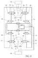
- the detection system of the second embodiment may also take the form of a third variant in which it comprises two first sensors 10b, 11b located on either side of a first axle box 4 of the first axle 9 of the body structure 6, and two second sensors 11c, 10c located on either side of a second axle box 4a of the second axle 9a located on the same side of the body structure 6 as the first box of axle 4.
- a first couple of sensors 10b, 10c which are more external with respect to the body structure 6 and a second pair of sensors 11b, 11c which are the most internal relative to the body structure 6.
- each sensor 10b, 10c, 11b, 11c is connected to a pneumatic power source 27b and to a control distributor 30a, 30b, 31a, 31b which is itself connected on the one hand to the control distributor 30b , 30a, 31b, 31a of the associated torque sensor 10c, 10b, 11c, 11b, and secondly connected to an OR function 32a, 32b.
- a first OR function 32a is common to the two control distributors 30a, 31a of the two sensors 10b, 11b located on the same first axle 9, and the second OR function 32b is common to the two control distributors 30b, 31b two sensors 10c, 11c located on the same second axle 9a.
- the first OR function 32a is connected to a first nonreturn valve 33a and the second OR function 32b is connected to a second nonreturn valve 33b, the two nonreturn valves 33a, 33b being connected to an annex system 28b.
- the first axle box 4 moves longitudinally along the arrow F7 to come into contacting contact on the contactor 36a of the sensor 11b by moving the switch 36a in the direction of the arrow F7, which results in compression the internal return spring 34a and the passage of the sensor 11b in the active open position, which concomitantly generates the passage of the pneumatic energy in the associated control valve 31a.
- This control distributor 31a then actuates closing the control valve 31b of the sensor 11c, preventing air from escaping through this sensor 11c and supplies the first OR function 32a which opens the first non-return valve 33a , closes the second check valve 33b and supplies the annex system 28b.
- the second sensor 11c With a delay time relative to the opening of the first sensor 11b, the second sensor 11c also opens by moving the second axle box 4a according to the arrow F7 until coming into contact support on the contactor 36b of the sensor 11c by moving this contactor 36b in the direction of the arrow F7,
- the control distributor 31b is kept in the closed position by the pneumatic energy sent by the control distributor 31a which was fed first .
- the second axle box 4a moves longitudinally along the arrow F7 to come into contact support on the contactor 36b of the sensor 11c by moving this sensor 11c in the direction of the arrow F7, which results in the compression of the internal return spring 34b and the passage of the sensor 11c in the active open position, which generates concomitantly the passage of the pneumatic energy in the associated control valve 31 b.
- This control distributor 31 b then actuates closing the control valve 31a of the sensor 11b by preventing air from escaping through this sensor 11b and supplies the second OR function 32b which opens the second non-return valve 33b, closes the first check valve 33a and feeds the annex system 28b.
- the second sensor 11b With a delay time relative to the opening of the first sensor 11c, the second sensor 11b also opens by moving the first axle box 4 according to the arrow F7 to come into contact support on the contactor 36a of the sensor 11b by moving the sensor 11b in the direction of the arrow F7.
- the control valve 31a is held in the closed position by the pneumatic energy sent by the control distributor 31b which has been fed first.
- the second axle box 4a moves longitudinally along the arrow F8 to come into contact support on the contactor 37b of the sensor 10c by moving the sensor 10c in the direction of the arrow F8, which results in the setting spring tension 35b and the passage of the sensor 10c in the active open position, which concomitantly generates the passage of the pneumatic energy in the associated control valve 30b.
- This control distributor 30b then actuates closing the control distributor 30a of the sensor 10b by preventing air from escaping by this sensor 10b and supplies the second OR function 32b which opens the second nonreturn valve 33b, closes the first check valve 33a and feeds the annex system 28b.
- the second sensor 10b With a time delay relative to the opening of the first sensor 10c, the second sensor 10b also opens by moving the first axle box 4 according to the arrow F8 to come into contact support on the contactor 37a of the sensor 10b by moving this sensor 10b in the direction of the arrow F8.
- the control distributor 30a is held in the closed position by the pneumatic energy sent by the control distributor 30b which has been fed first.
- the first axle box 4 moves longitudinally along the arrow F8 to come into contact support on the contactor 37a of the sensor 10b by moving the sensor 10b in the direction of the arrow F8, which results in the setting the tension of the spring 35a and the passage of the sensor 10b in the active open position, which concomitantly generates the passage of the pneumatic energy in the associated control distributor 30a.
- This control distributor 30a then actuates closing the control distributor 30b of the sensor 10c by preventing air from escaping by this sensor 10c and supplies the first OR function 32a which opens the first non-return valve 33a, closes the second non-return valve 33b and feeds the annex system 28b.
- the second sensor 10c With a delay time relative to the opening of the first sensor 10b, the second sensor 10c also opens by moving the second axle box 4a along the arrow F8 to come into contact support on the contactor 37b of the sensor 10c by moving this sensor 10c in the direction of the arrow F8.
- the control distributor 30b is held in the closed position by the pneumatic energy sent by the control distributor 30a which has been fed first.
Abstract
L'invention porte principalement sur une structure de caisse de véhicule ferroviaire équipée d'au moins un système de détection de l'entrée en courbe de ladite structure de caisse non équipé de bogie, et qui est essentiellement caractérisée en ce qu'elle comporte au moins un capteur mécanique (10, 11) relié à une source d'énergie pneumatique (27) et à un système annexe (28) en le rendant apte à mettre en communication la dite source d'énergie au dit système annexe, en ce que le dit capteur est solidarisé à la structure de caisse (6) en étant disposé à proximité de la boîte d'essieu (3, 4) à une distance au moins égale à la course pouvant s'opérer selon l'axe principal de contact du capteur entre la boite d'essieu et la structure de caisse lorsque cette dernière est en ligne droite, et en ce que le capteur : - adopte une première position inactive libre par rapport à la boîte d'essieu correspondant à une circulation de la structure de caisse en ligne droite et dans laquelle le dit capteur interdit l'alimentation en énergie pneumatique du système annexe, et - adopte une second position active en appui de contact contre la boite d'essieu correspondant à une circulation de la structure de caisse dans une courbe et dans laquelle le capteur autorise l'alimentation en énergie pneumatique du système annexe.The invention relates mainly to a rail vehicle body structure equipped with at least one curve entry detection system of said body structure without bogie, and which is essentially characterized in that it comprises at least one at least one mechanical sensor (10, 11) connected to a pneumatic energy source (27) and to an auxiliary system (28) making it suitable for putting said energy source into communication with said ancillary system, in that said sensor is secured to the body structure (6) by being placed close to the axle box (3, 4) at a distance at least equal to the stroke that can take place along the main axis of contact of the sensor between the axle box and the body structure when the latter is in a straight line, and in that the sensor: adopts a first free inactive position relative to the axle box corresponding to a circulation of the body structure in a straight line and in which said sensor prohibits the pneumatic energy supply of the ancillary system, and - Adopts a second active position in contact support against the axle box corresponding to a circulation of the body structure in a curve and in which the sensor allows the pneumatic power supply of the ancillary system.
Description
L'invention concerne une structure de caisse de véhicule ferroviaire équipée d'au moins un système de détection de l'entrée en courbe de ladite structure de caisse.The invention relates to a railway vehicle body structure equipped with at least one system for detecting the entry curve of said body structure.
La circulation d'un véhicule ferroviaire dans une courbe engendre un effort latéral important au niveau du contact entre la roue et le rail de l'essieu avant d'une structure de caisse, qui oblige l'essieu à suivre la courbe en pivotant relativement à la structure de caisse.The movement of a railway vehicle in a curve generates a significant lateral force at the contact between the wheel and the rail of the front axle of a body structure, which forces the axle to follow the curve by pivoting relatively to the cash structure.
Le pivotement de l'essieu, et donc la prise de courbe associée, est une information qui prend toute son importance lorsque l'on souhaite par exemple piloter un système annexe uniquement dans les courbes. Il pourra s'agir par exemple d'un système de lubrification de boudin de roue. Il s'agit donc de détecter la prise de courbe pour alimenter un système annexe.The pivoting of the axle, and therefore the associated curve taking, is an information that is very important when, for example, it is desired to control an ancillary system only in the curves. This could be for example a wheel flange lubrication system. It is thus a question of detecting the taking of curve to feed an annexed system.
A la connaissance de la demanderesse, le seul système mécanique existant pour détecter l'entrée en courbe d'un matériel ferroviaire consiste en un système de renvoi par tringles dans lequel une première tringle est montée sur l'axe d'un bogie, et entraîne en pivotement une second tringle entraînant elle-même en pivotement une tôle dont les extrémités sont aptes à passer d'une première position inactive dans laquelle une extrémité est en contact magnétique avec un aimant solidaire de la structure de caisse, à une seconde position active dans laquelle l'extrémité en question n'est plus en contact avec cet aimant, ce dont il résulte que le bogie a pivoté par rapport à la structure de caisse et que le véhicule ferroviaire est en courbe.To the knowledge of the applicant, the only existing mechanical system for detecting the entry curve of a railway material consists of a system of return rods in which a first rod is mounted on the axis of a bogie, and causes in pivoting a second bead itself driving a sheet in turn, the ends of which are capable of passing from a first inactive position in which one end is in magnetic contact with a magnet secured to the body structure, to a second active position in the end in question is no longer in contact with the magnet, which results in the bogie pivoted relative to the body structure and the rail vehicle is curved.
Néanmoins, ce système est complexe, volumineux, difficile à étalonner et nécessairement associé à un véhicule ferroviaire muni de bogies.Nevertheless, this system is complex, bulky, difficult to calibrate and necessarily associated with a railway vehicle equipped with bogies.
Dans ce contexte, la présente invention vise une structure de caisse de véhicule ferroviaire équipée d'au moins un système de détection de l'entrée en courbe de ladite structure de caisse, le dit système de détection étant à la fois simple, peu volumineux et adaptable sur une structure de caisse non équipée de bogies.In this context, the present invention aims at a rail vehicle body structure equipped with at least one system for detecting the entry into curve of said body structure, said detection system being at the same time simple, not bulky and adaptable to a body structure not equipped with bogies.
À cet effet, la structure de caisse de véhicule ferroviaire de l'invention équipée d'au moins un système de détection de l'entrée en courbe de ladite structure de caisse est essentiellement caractérisée en ce qu'elle comporte au moins un capteur mécanique s'étendant selon un axe principal de contact et relié à une source d'énergie pneumatique et à un système annexe en le rendant apte à mettre en communication la dite source d'énergie au dit système annexe, en ce que le dit capteur est solidarisé à la structure de caisse en étant disposé à proximité de la boîte d'essieu à une distance au moins égale à la course pouvant s'opérer selon l'axe principal de contact du capteur entre la boite d'essieu (3,4,4a) et la structure de caisse lorsque cette dernière est en ligne droite, et en ce que le capteur :
- adopte une première position inactive libre par rapport à la boîte d'essieu correspondant à une circulation de la structure de caisse en ligne droite et dans laquelle le dit capteur interdit l'alimentation en énergie pneumatique du système annexe, et
- adopte une second position active en appui de contact contre la boite d'essieu correspondant à une circulation de la structure de caisse dans une courbe et dans laquelle le capteur autorise l'alimentation en énergie pneumatique du système annexe.
- adopts a first free idle position relative to the axle box corresponding to a circulation of the body structure in a straight line and wherein said sensor prohibits the pneumatic power supply of the ancillary system, and
- adopts a second active position in contact support against the axle box corresponding to a circulation of the body structure in a curve and in which the sensor allows the pneumatic energy supply of the ancillary system.
Le système de détection peut également comporter les caractéristiques optionnelles suivantes considérées isolément ou selon toutes les combinaisons techniques possibles :
- le capteur est muni d'un contacteur monté sur un ressort de rappel en compression lorsque le dit capteur est dans sa position active en appui de contact contre la boite d'essieu en faisant opérer une course de déplacement au contacteur selon l'axe principal de contact, et en ce que le capteur est monté mobile en translation selon son axe principal de contact sur une plaque de garde solidaire de la structure de caisse, la translation du capteur sur la plaque de garde faisant opérer une course de déplacement au dit capteur.
- le capteur est monté sur au moins un ressort de renvoi solidaire de la plaque de garde et dont la flexibilité est inférieure à celle du ressort de rappel du capteur.
- la structure de caisse comporte deux capteurs situés du même côté des boites d'essieu opposées d'un même essieu.
- la structure de caisse comporte au moins deux capteurs situés de part et d'autre d'une même boîte d'essieu en opposition de sens et en alignement d'axe principal de contact.
- la structure de caisse comporte deux capteurs situés de part et d'autre d'une même boîte d'essieu elle-même disposée sur un côté d'un premier essieu de la structure de caisse, et deux capteurs situés de part et d'autre d'une même boîte d'essieu disposée du même côté d'un second essieu de la même structure de caisse en formant :
- un premier couple de capteurs constitué des deux capteurs les plus externes relativement à la structure de caisse et aptes à être amenés dans leur seconde position active lors d'un premier type de prise de courbe,
- un second couple de capteurs constitué des deux capteurs les plus internes relativement à la structure de caisse et apte à être amenés dans leur seconde position active lors d'un second type de prise de courbe opposée à au premier.
- chaque capteur est relié une alimentation en air et à un distributeur de commande lui-même relié au système annexe, et le passage du capteur considéré dans sa seconde position active entraîne l'ouverture du dit capteur et de son distributeur de commande associé qui alimente alors le système annexe.
- les distributeurs de commande associés à un même couple de capteurs sont reliés entre eux de façon que lors d'une prise de courbe, l'ouverture du premier distributeur de commande entraîne la fermeture du second distributeur de commande.
- the sensor is provided with a contactor mounted on a compression spring when the said sensor is in its active position in contact support against the axle box by operating a displacement stroke to the contactor along the main axis of contact, and in that the sensor is movably mounted in translation along its main contact axis on a guard plate secured to the body structure, the translation of the sensor on the guard plate causing a displacement stroke to said sensor.
- the sensor is mounted on at least one return spring secured to the guard plate and whose flexibility is less than that of the sensor return spring.
- the body structure comprises two sensors located on the same side of the opposite axle boxes of the same axle.
- the body structure comprises at least two sensors located on either side of the same axle box in opposite directions and in alignment with the main contact axis.
- the body structure comprises two sensors located on either side of the same axle box itself disposed on one side of a first axle of the body structure, and two sensors located on either side of the same axle box arranged on the same side of a second axle of the same body structure, forming:
- a first pair of sensors consisting of the two most external sensors relative to the body structure and able to be brought into their second active position during a first type of curve taking,
- a second pair of sensors consisting of the two most internal sensors relative to the body structure and adapted to be brought into their second active position in a second type of curving opposite to the first.
- each sensor is connected to an air supply and to a control distributor itself connected to the ancillary system, and the passage of the sensor considered in its second active position causes the opening of said sensor and its associated control distributor which then feeds the annex system.
- the control distributors associated with the same pair of sensors are interconnected so that when taking a curve, the opening of the first control valve causes the closing of the second control valve.
D'autres caractéristiques et avantages de l'invention ressortiront clairement de la description qui en est donnée ci-dessous, à titre indicatif et nullement limitatif, en référence aux figures annexées parmi lesquelles :
- la
figure 1 est une représentation schématique du système de détection de l'entrée en courbe équipant la structure de caisse de l'invention et selon une première variante dans laquelle deux capteurs sont disposés de part et d'autre d'une boîte d'essieu, - la
figure 2 est une représentation de face de la plaque de garde sur laquelle est monté le système de détection, - la
figure 3 est une représentation de côté du système de détection selon la flèche III de lafigure 1 , - la
figure 4 est une représentation de dessous du système de détection selon la flèche IV de lafigure 1 , - la
figure 5 est une représentation schématique du système de détection selon sa première variante, ainsi que de son circuit de détection de l'entrée et de la sortie en courbe associé, - la
figure 6 est une représentation schématique du système de détection selon une deuxième variante dans laquelle deux capteurs sont situés du même côté de deux boites d'essieu opposées, ainsi que de son circuit de détection de l'entrée et de la sortie en courbe associé, - la
figure 7 est une représentation schématique en transparence et de dessus d'une structure de caisse de véhicule ferroviaire circulant dans le même sens que celui défini par la courbe et équipée du système de détection selon une troisième variante dans laquelle deux capteurs sont situés de part et d'autre de la boîte d'essieu avant et deux capteurs sont situés de part et d'autre de la boîte d'essieu arrière, - la
figure 8 est une représentation schématique en transparence et de dessus d'une structure de caisse de véhicule ferroviaire circulant en ligne droite et équipée du système de détection selon la troisième variante, - la
figure 9 est une représentation schématique en transparence et de dessus d'une structure de caisse de véhicule ferroviaire circulant dans le sens opposé de celui défini par la courbe et équipée du système de détection selon la troisième variante, et - la
figure 10 est une représentation schématique du système de détection selon la troisième variante, ainsi que de son circuit de détection de l'entrée et de la sortie en courbe associé.
- the
figure 1 is a schematic representation of the curve entry detection system equipping the body structure of the invention and according to a first variant in which two sensors are arranged on either side of an axle box, - the
figure 2 is a front view of the guard plate on which the detection system is mounted, - the
figure 3 is a side representation of the detection system according to arrow III of thefigure 1 , - the
figure 4 is a bottom representation of the detection system according to arrow IV of thefigure 1 , - the
figure 5 is a schematic representation of the detection system according to its first variant, as well as its detection circuit of the input and the associated curve output, - the
figure 6 is a schematic representation of the detection system according to a second variant in which two sensors are located on the same side of two opposite axle boxes, as well as its detection circuit of the input and the associated curve output, - the
figure 7 is a schematic representation in transparency and from above of a rail vehicle body structure flowing in the same direction as that defined by the curve and equipped with the detection system according to a third variant in which two sensors are located on the side and another of the front axle box and two sensors are located on both sides of the rear axle box, - the
figure 8 is a schematic representation in transparency and from above of a rail vehicle body structure traveling in a straight line and equipped with the detection system according to the third variant, - the
figure 9 is a schematic representation in transparency and from above of a rail vehicle body structure traveling in the opposite direction to that defined by the curve and equipped with the detection system according to the third variant, and - the
figure 10 is a schematic representation of the detection system according to the third variant, as well as its detection circuit of the input and the associated curve output.
Le système de détection de l'entrée en courbe d'une structure de caisse de véhicule ferroviaire de l'invention utilise le mouvement relatif entre la structure de caisse d'un véhicule ferroviaire et les boîtes d'essieu. Le système de détection prévoit au moins un capteur mécanique solidaire de la structure de caisse, qui adopte une position inactive libre par rapport à la boîte d'essieu lorsque la structure de caisse circule en ligne droite, et une position active de contact sur la boîte d'essieu lorsque la structure de caisse entre et circule en courbe. Le passage de la position inactive à la position active du capteur s'opère par une course longitudinale de la boîte d'essieu relativement à la structure de caisse lorsque cette dernière est en courbe, en venant en appui sur le capteur.The curved entry detection system of a railway vehicle body structure of the invention uses the relative movement between the body structure of a railway vehicle and the axle boxes. The detection system provides at least one mechanical sensor integral with the body structure, which adopts an idle free position with respect to the axle box when the body structure travels in a straight line, and an active contact position on the axle box when the body structure enters and circulates. The transition from the inactive position to the active position of the sensor is effected by a longitudinal stroke of the axle box relative to the body structure when the latter is in curve, bearing on the sensor.
La structure de caisse repose sur des essieux 9 qui sont, comme illustré sur la
En référence à la
Le système de détection comporte au moins un capteur mécanique à galet ou à poussoir 10, ou capteur TOR, s'étendant selon un axe principal de contact BB', solidarisé à la structure de caisse 6 et situé à proximité et sans contact dans sa position inactive fermée de la boîte d'essieu 4. Lorsque la structure de caisse 6 entre en courbe, la boite d'essieu 4 se déplace longitudinalement selon les axes XX' et BB' jusqu'à venir en contact avec le contacteur du capteur 10 en le faisant passer dans sa position active ouverte.The detection system comprises at least one mechanical roller or
Plus précisément, et selon une première variante représentée sur les
Chaque capteur 10,11 est fixé à un support 18 (
Plus précisément et en référence à la
Comme illustré sur les
En référence à la
Pour une course longitudinale maximum de la boite d'essieu 4 de 22,5 millimètres, voire de 26,5 millimètres après usure, le capteur 10 est positionné sur sa plaque de garde associée 12 de façon à respecter une certaine distance a entre la boite d'essieu 4 et la tête du contacteur 25 de ce capteur 10. Cette distance a doit être au moins égale à la course longitudinale de la boite d'essieu 4 pouvant s'opérer en ligne droite afin d'éviter que le capteur 10 ne soit activé en position ouverte tant que le matériel n'est pas en courbe. Cette course longitudinale en ligne droite est, selon l'empattement du matériel, comprise entre 3,5 et 6 millimètres. Selon ce mode de réalisation, le contacteur 25 du capteur 10 est situé à une distance a de 6 millimètres de la boîte d'essieu 4.For a maximum longitudinal stroke of the
Ainsi, tant que la course longitudinale de la boîte d'essieu 4 relativement à la structure de caisse 6 est inférieure à 6 millimètres, le ressort de rappel 122 du capteur 10 est en position de détente, de sorte que ce capteur 10 reste en position inactive fermée.Thus, as long as the longitudinal stroke of the
Lorsque le matériel entre en courbe, la course longitudinale de la boîte d'essieu 4 devient supérieure à 6 millimètres et la boite d'essieu 4 appuie sur le contacteur 25 du capteur considéré 10, ce dont il résulte la mise en compression du ressort de rappel 122 et l'entraînement en position active du dit capteur 10. Jusqu'à la course maximale b du capteur 10 qui est généralement de 10 millimètres, le ressort de rappel interne 122 est comprimé, tandis que le double ressort de renvoi externe 22 reste en position de détente en raison de sa flexibilité inférieure à celle du ressort de rappel interne 122 des capteurs 10.When the material enters in curve, the longitudinal stroke of the
Une fois que le contacteur 25 est en butée dans le capteur 10, ce qui correspond à une course de la boîte d'essieu 4 au moins égale à 16 millimètres, le double ressort de renvoi 22 se comprime le long de sa course c (
Ainsi, le contact entre le contacteur 25 du capteur 10 et la boîte d'essieu 4 s'opère à partir d'une course longitudinale de la boîte d'essieu 4 de 6 millimètres et jusqu'à une course maximum longitudinale de 22,5 millimètres ou de 26,5 millimètres.Thus, the contact between the
La course du contacteur 25 est ainsi scindée en deux : une partie de sa course est engendrée par la compression du ressort de rappel interne 122 tandis que le double ressort de renvoi 22 est en détente, et l'autre partie par la compression du double ressort de renvoi 22 tandis que le ressort de rappel interne 122 est maintenu en compression. Ce système permet ainsi d'augmenter la longueur de la course intrinsèque du capteur 10.The stroke of the
A l'inverse, depuis sa position active ouverte, le capteur 10 bascule en position fermée lorsque la course longitudinale de la boîte d'essieu 4 devient inférieure à 6 millimètres.Conversely, from its active open position, the
Toujours en référence à la
Lorsque les capteurs 10,11 sont en position inactive fermée comme représenté sur cette figure, la source d'énergie pneumatique 27 n'alimente pas le système annexe 28.When the
Lorsque la structure de caisse 6, non visible sur cette figure et qui circule selon le sens de la flèche S, entre dans une courbe à droite, la boite d'essieu 4 se déplace longitudinalement selon la flèche F4 jusqu'à venir en appui de contact sur le contacteur 25 du capteur 10 en déplaçant le capteur 10 dans la direction de la flèche F4, ce dont il résulte la compression du ressort de rappel interne 122 et le passage du capteur 10 en position ouverte active, ce qui engendre de façon concomitante l'alimentation du système annexe 28 par la source d'énergie pneumatique 27 via ce capteur 10.When the
A l'inverse, lorsque la structure de caisse 6 circule de nouveau en ligne droite ou sort de courbe, le contacteur 25 est libéré de l'appui de contact avec la boîte d'essieu 4, le ressort de rappel interne 122 revient en position de détente en entraînant le capteur 10 en position inactive fermée interdisant l'alimentation du système annexe 28 par la source d'énergie pneumatique 27.Conversely, when the
De la même façon, lorsque la structure de caisse 6 circule toujours selon le sens de la flèche S, mais entre dans une courbe à gauche, la boite d'essieu 4 se déplace longitudinalement selon la flèche F3 jusqu'à venir en appui de contact sur le contacteur 26 du capteur 11 en déplaçant ce capteur 11 dans la direction de la flèche F3, ce dont il résulte la compression du ressort de rappel interne 123 et le passage du capteur 11 en position ouverte active, et ce qui engendre de façon concomitante l'alimentation du système annexe 28 par la source d'énergie pneumatique 27 via ce capteur 11.In the same way, when the
A l'inverse, lorsque la structure de caisse 6 circule de nouveau en ligne droite ou sort de courbe, le contacteur 26 est libéré de l'appui de contact avec la boîte d'essieu 4, le ressort de rappel interne 123 revient en position de détente en entraînant le capteur 11 en position inactive fermée interdisant l'alimentation du système annexe 28 par la source d'énergie pneumatique 27.Conversely, when the
En référence à la
Comme pour la première variante, chaque capteur 10a,11a est relié à une source d'énergie pneumatique 27a et à un système annexe 28a.As for the first variant, each
Lorsque les capteurs 10a,11a sont en position inactive fermée comme représenté sur cette figure, la source d'énergie pneumatique 27a n'alimente pas le système annexe 28a.When the
Lorsque la structure de caisse 6, non visible sur cette figure et qui circule selon le sens de la flèche S1, entre dans une courbe à gauche, la boite d'essieu 4 se déplace longitudinalement selon la flèche F5 (tandis que la boîte d'essieu opposée 3 se déplace dans la direction inverse selon la flèche F6), jusqu'à venir en appui de contact sur le contacteur 25a du capteur 10a en déplaçant le capteur 10a dans la direction de la flèche F5 sous l'effet de la mise sous compression du ressort de rappel interne 122a, ce qui provoque le passage du capteur 10a en position ouverte active, et ce qui engendre de façon concomitante l'alimentation du système annexe 28a par la source d'énergie pneumatique 27a via ce capteur 10a.When the
A l'inverse, lorsque la structure de caisse 6 circule de nouveau en ligne droite ou sort de courbe, le contacteur 25a est libéré de l'appui de contact avec la boîte d'essieu 4, le ressort de rappel interne 122a revient en position de détente en entraînant le capteur 10a en position inactive fermée interdisant l'alimentation du système annexe 28a par la source d'énergie pneumatique 27a.On the other hand, when the
De la même façon lorsque la structure de caisse 6 circule toujours selon le sens de la flèche S1, mais entre dans une courbe à droite, la boite d'essieu 3 se déplace longitudinalement selon la flèche F5 (tandis que la boîte d'essieu opposée 4 se déplace dans la direction inverse selon la flèche F6) jusqu'à venir en appui de contact sur la contacteur 26a du capteur 11a dans la direction de la flèche F5, ce dont il résulte la compression du ressort de rappel interne 123a et le passage du capteur 11a en position ouverte active, ce qui engendre de façon concomitante l'alimentation du système annexe 28a par la source d'énergie pneumatique 27a via ce capteur 11a.In the same way when the
A l'inverse, lorsque la structure de caisse 6 circule de nouveau en ligne droite ou sort de courbe, le contacteur 26a est libéré de l'appui de contact avec la boîte d'essieu 3, le ressort de rappel interne 123a revient en position de détente en entraînant le capteur 11a en position inactive fermée interdisant l'alimentation du système annexe 28a par la source d'énergie pneumatique 27a.Conversely, when the
En référence aux
On distingue deux couples de capteurs dont la fonctionnalité associée est expliquée en référence à la
En référence à la
Lorsque la structure de caisse 6 prend une courbe à gauche en circulant vers la gauche selon la flèche S2 de la
Lorsque la structure de caisse 6 prend une courbe à droite en circulant vers la droite selon la flèche S3 de la
Lorsque la structure de caisse 6 prend une courbe à gauche en circulant vers la droite selon la flèche S5 de la
Lorsque la structure de caisse 6 prend une courbe à droite en circulant vers la gauche selon la flèche S4 de la
Claims (8)
Applications Claiming Priority (1)
| Application Number | Priority Date | Filing Date | Title |
|---|---|---|---|
| FR1500651A FR3034391B1 (en) | 2015-04-01 | 2015-04-01 | SYSTEM FOR DETECTING THE CURVED INPUT OF A RAIL VEHICLE BODY STRUCTURE |
Publications (1)
| Publication Number | Publication Date |
|---|---|
| EP3078562A1 true EP3078562A1 (en) | 2016-10-12 |
Family
ID=53514241
Family Applications (1)
| Application Number | Title | Priority Date | Filing Date |
|---|---|---|---|
| EP16163131.2A Withdrawn EP3078562A1 (en) | 2015-04-01 | 2016-03-31 | System for detecting when a railway vehicle body structure enters a curve |
Country Status (2)
| Country | Link |
|---|---|
| EP (1) | EP3078562A1 (en) |
| FR (1) | FR3034391B1 (en) |
Citations (5)
| Publication number | Priority date | Publication date | Assignee | Title |
|---|---|---|---|---|
| FR2474423A1 (en) * | 1980-01-30 | 1981-07-31 | Schweizerische Lokomotiv | DEVICE FOR CONTROLLING THE ROTATION MOVEMENT OF A RAILWAY MOUNTED AXLE OF A VEHICLE ON PASSING IN A CURVE |
| FR2594936A1 (en) * | 1985-10-08 | 1987-08-28 | Madison Kipp Corp | AUTOMATIC LUBRICATION APPARATUS |
| CA2014168C (en) * | 1989-04-10 | 1994-07-19 | Michel Rimbaud | Primary suspension and variable orientation axle |
| JP2010111329A (en) * | 2008-11-07 | 2010-05-20 | Kinki Sharyo Co Ltd | Method and device for applying on-vehicle lubricant of railroad rolling stock |
| US20140311378A1 (en) * | 2011-12-19 | 2014-10-23 | Nippon Steel & Sumitomo Metal Corporation | Railway vehicle steering truck |
-
2015
- 2015-04-01 FR FR1500651A patent/FR3034391B1/en active Active
-
2016
- 2016-03-31 EP EP16163131.2A patent/EP3078562A1/en not_active Withdrawn
Patent Citations (5)
| Publication number | Priority date | Publication date | Assignee | Title |
|---|---|---|---|---|
| FR2474423A1 (en) * | 1980-01-30 | 1981-07-31 | Schweizerische Lokomotiv | DEVICE FOR CONTROLLING THE ROTATION MOVEMENT OF A RAILWAY MOUNTED AXLE OF A VEHICLE ON PASSING IN A CURVE |
| FR2594936A1 (en) * | 1985-10-08 | 1987-08-28 | Madison Kipp Corp | AUTOMATIC LUBRICATION APPARATUS |
| CA2014168C (en) * | 1989-04-10 | 1994-07-19 | Michel Rimbaud | Primary suspension and variable orientation axle |
| JP2010111329A (en) * | 2008-11-07 | 2010-05-20 | Kinki Sharyo Co Ltd | Method and device for applying on-vehicle lubricant of railroad rolling stock |
| US20140311378A1 (en) * | 2011-12-19 | 2014-10-23 | Nippon Steel & Sumitomo Metal Corporation | Railway vehicle steering truck |
Also Published As
| Publication number | Publication date |
|---|---|
| FR3034391B1 (en) | 2017-03-17 |
| FR3034391A1 (en) | 2016-10-07 |
Similar Documents
| Publication | Publication Date | Title |
|---|---|---|
| EP0724279B1 (en) | Window winder for vehicles with oscillating arm and toothed sector | |
| EP1703022A1 (en) | Improved gate | |
| FR2957068A1 (en) | DOCKING DEVICE OF A GOODS TRANSPORT VEHICLE AND INSTALLATION COMPRISING SAME | |
| FR2714651A1 (en) | Energy absorbing device for a motor vehicle steering column. | |
| EP2193063B1 (en) | Rail bogie having wheels which can be oriented according to the curvature of the track | |
| EP3473513B1 (en) | Step for a railway vehicle, associated door system, railway vehicle and method | |
| EP3078562A1 (en) | System for detecting when a railway vehicle body structure enters a curve | |
| FR2885158A1 (en) | VEHICLE WITH A TAILGATE | |
| EP1597101B1 (en) | Retractable roof for a vehicle | |
| WO2006131608A1 (en) | Device for moving vehicles | |
| BE494574A (en) | REDUCIBLE BICYCLE WITH A MICROMOTOR | |
| EP2734389B1 (en) | Amphibious vehicle | |
| EP3075624B1 (en) | Detecting device of a bend for a railway vehicle equipped with boggies | |
| EP2152562B1 (en) | Bidirectional guidance system with lateral oscillation limiting, for road axle guided by a rail on the ground. | |
| FR3045529A1 (en) | RETRACTABLE FOOTBOARD FOR MOTOR VEHICLE. | |
| FR2886369A1 (en) | DUAL-CONTROLLED DEVICE FOR OPENING CLOSURE OF A VALVE, IN PARTICULAR A TANK DRAIN AND WAGON COMPRISING A TANK EQUIPPED WITH A DOUBLE-CONTROL DEVICE SUCH AS PRECIOUS | |
| EP2529996B1 (en) | Locking device for a steering system of a motor vehicle | |
| FR2897773A1 (en) | TRANSPORT VEHICLE PROVIDED WITH ACCESS MEANS FOR PEOPLE WITH REDUCED MOBILITY | |
| WO2024018048A1 (en) | System for manually immobilizing a vehicle in front of a loading dock | |
| FR2800786A1 (en) | Motorized roller for door leaf has motorized roller housing slidably mounted in bracket and sprung downward to increase traction | |
| EP1445153B1 (en) | Vehicle with a retractable underrun protection bar | |
| FR3053012A1 (en) | AUTOMOTIVE VEHICLE LUGGAGE COMPARTMENT REPAIR SYSTEM | |
| FR3124994A1 (en) | Packing element comprising a movable part that can be moved automatically or manually | |
| BE470273A (en) | ||
| FR2906502A1 (en) | Passenger compartment's covering element displacing device for e.g. car, has rails in each side of front, intermediate and rear panels, and respectively including end portions following rectilinear portions that extend parallel to panels |
Legal Events
| Date | Code | Title | Description |
|---|---|---|---|
| PUAI | Public reference made under article 153(3) epc to a published international application that has entered the european phase |
Free format text: ORIGINAL CODE: 0009012 |
|
| AK | Designated contracting states |
Kind code of ref document: A1 Designated state(s): AL AT BE BG CH CY CZ DE DK EE ES FI FR GB GR HR HU IE IS IT LI LT LU LV MC MK MT NL NO PL PT RO RS SE SI SK SM TR |
|
| AX | Request for extension of the european patent |
Extension state: BA ME |
|
| STAA | Information on the status of an ep patent application or granted ep patent |
Free format text: STATUS: THE APPLICATION HAS BEEN PUBLISHED |
|
| STAA | Information on the status of an ep patent application or granted ep patent |
Free format text: STATUS: THE APPLICATION IS DEEMED TO BE WITHDRAWN |
|
| 18D | Application deemed to be withdrawn |
Effective date: 20170413 |