EP3078287A1 - Shoe, in particular a sports shoe, and method for the manufacture thereof - Google Patents
Shoe, in particular a sports shoe, and method for the manufacture thereof Download PDFInfo
- Publication number
- EP3078287A1 EP3078287A1 EP16153027.4A EP16153027A EP3078287A1 EP 3078287 A1 EP3078287 A1 EP 3078287A1 EP 16153027 A EP16153027 A EP 16153027A EP 3078287 A1 EP3078287 A1 EP 3078287A1
- Authority
- EP
- European Patent Office
- Prior art keywords
- shoe
- region
- foot
- gap
- sole unit
- Prior art date
- Legal status (The legal status is an assumption and is not a legal conclusion. Google has not performed a legal analysis and makes no representation as to the accuracy of the status listed.)
- Granted
Links
- 238000000034 method Methods 0.000 title claims abstract description 23
- 238000004519 manufacturing process Methods 0.000 title claims abstract description 20
- 210000000452 mid-foot Anatomy 0.000 claims abstract description 74
- 210000002683 foot Anatomy 0.000 claims description 92
- 239000000463 material Substances 0.000 claims description 81
- 230000003014 reinforcing effect Effects 0.000 claims description 66
- 210000004744 fore-foot Anatomy 0.000 claims description 27
- 239000002245 particle Substances 0.000 description 36
- 230000003044 adaptive effect Effects 0.000 description 22
- 210000002346 musculoskeletal system Anatomy 0.000 description 14
- 239000004433 Thermoplastic polyurethane Substances 0.000 description 13
- 229920002803 thermoplastic polyurethane Polymers 0.000 description 13
- 229920005983 Infinergy® Polymers 0.000 description 11
- 239000004952 Polyamide Substances 0.000 description 11
- 229920002647 polyamide Polymers 0.000 description 11
- 229920002994 synthetic fiber Polymers 0.000 description 9
- 230000005855 radiation Effects 0.000 description 8
- 229920002334 Spandex Polymers 0.000 description 7
- 238000013461 design Methods 0.000 description 7
- 239000006260 foam Substances 0.000 description 7
- 230000005021 gait Effects 0.000 description 7
- 230000001965 increasing effect Effects 0.000 description 7
- -1 polyethylene Polymers 0.000 description 7
- 229920002614 Polyether block amide Polymers 0.000 description 6
- 239000010985 leather Substances 0.000 description 6
- 239000004698 Polyethylene Substances 0.000 description 5
- 239000004743 Polypropylene Substances 0.000 description 5
- 230000008901 benefit Effects 0.000 description 5
- 230000001419 dependent effect Effects 0.000 description 5
- 239000004744 fabric Substances 0.000 description 5
- 229920000573 polyethylene Polymers 0.000 description 5
- 229920001155 polypropylene Polymers 0.000 description 5
- 239000004753 textile Substances 0.000 description 5
- 239000011324 bead Substances 0.000 description 4
- 238000009940 knitting Methods 0.000 description 4
- 229920000742 Cotton Polymers 0.000 description 3
- 239000011230 binding agent Substances 0.000 description 3
- 230000006378 damage Effects 0.000 description 3
- 230000000694 effects Effects 0.000 description 3
- 239000002649 leather substitute Substances 0.000 description 3
- 238000000465 moulding Methods 0.000 description 3
- 239000005445 natural material Substances 0.000 description 3
- 239000004814 polyurethane Substances 0.000 description 3
- 230000008569 process Effects 0.000 description 3
- 239000004759 spandex Substances 0.000 description 3
- 230000006641 stabilisation Effects 0.000 description 3
- 239000004575 stone Substances 0.000 description 3
- 210000002435 tendon Anatomy 0.000 description 3
- 238000012360 testing method Methods 0.000 description 3
- 230000006978 adaptation Effects 0.000 description 2
- 230000000386 athletic effect Effects 0.000 description 2
- 238000005452 bending Methods 0.000 description 2
- 238000006243 chemical reaction Methods 0.000 description 2
- 230000005674 electromagnetic induction Effects 0.000 description 2
- 230000005670 electromagnetic radiation Effects 0.000 description 2
- 239000005038 ethylene vinyl acetate Substances 0.000 description 2
- 239000011888 foil Substances 0.000 description 2
- 238000009533 lab test Methods 0.000 description 2
- 238000007639 printing Methods 0.000 description 2
- 230000002787 reinforcement Effects 0.000 description 2
- 230000000717 retained effect Effects 0.000 description 2
- 238000009958 sewing Methods 0.000 description 2
- 230000003019 stabilising effect Effects 0.000 description 2
- 238000011105 stabilization Methods 0.000 description 2
- 210000003371 toe Anatomy 0.000 description 2
- 238000003466 welding Methods 0.000 description 2
- 229920006309 Invista Polymers 0.000 description 1
- 210000003484 anatomy Anatomy 0.000 description 1
- 210000003423 ankle Anatomy 0.000 description 1
- 238000013459 approach Methods 0.000 description 1
- 230000004888 barrier function Effects 0.000 description 1
- 230000037396 body weight Effects 0.000 description 1
- DQXBYHZEEUGOBF-UHFFFAOYSA-N but-3-enoic acid;ethene Chemical compound C=C.OC(=O)CC=C DQXBYHZEEUGOBF-UHFFFAOYSA-N 0.000 description 1
- 230000008859 change Effects 0.000 description 1
- 230000002708 enhancing effect Effects 0.000 description 1
- 238000003780 insertion Methods 0.000 description 1
- 230000037431 insertion Effects 0.000 description 1
- 230000007794 irritation Effects 0.000 description 1
- 238000005259 measurement Methods 0.000 description 1
- 239000008188 pellet Substances 0.000 description 1
- 229920001200 poly(ethylene-vinyl acetate) Polymers 0.000 description 1
- 229920002635 polyurethane Polymers 0.000 description 1
- 230000001144 postural effect Effects 0.000 description 1
- 239000012779 reinforcing material Substances 0.000 description 1
- 230000035807 sensation Effects 0.000 description 1
- 238000007493 shaping process Methods 0.000 description 1
- 230000004936 stimulating effect Effects 0.000 description 1
- 238000004154 testing of material Methods 0.000 description 1
- 229920002725 thermoplastic elastomer Polymers 0.000 description 1
- 238000009423 ventilation Methods 0.000 description 1
- 230000000007 visual effect Effects 0.000 description 1
- XLYOFNOQVPJJNP-UHFFFAOYSA-N water Substances O XLYOFNOQVPJJNP-UHFFFAOYSA-N 0.000 description 1
Images


Classifications
-
- A—HUMAN NECESSITIES
- A43—FOOTWEAR
- A43B—CHARACTERISTIC FEATURES OF FOOTWEAR; PARTS OF FOOTWEAR
- A43B23/00—Uppers; Boot legs; Stiffeners; Other single parts of footwear
- A43B23/02—Uppers; Boot legs
- A43B23/0245—Uppers; Boot legs characterised by the constructive form
-
- A—HUMAN NECESSITIES
- A43—FOOTWEAR
- A43B—CHARACTERISTIC FEATURES OF FOOTWEAR; PARTS OF FOOTWEAR
- A43B7/00—Footwear with health or hygienic arrangements
- A43B7/14—Footwear with health or hygienic arrangements with foot-supporting parts
- A43B7/28—Adapting the inner sole or the side of the upper of the shoe to the sole of the foot
-
- A—HUMAN NECESSITIES
- A43—FOOTWEAR
- A43B—CHARACTERISTIC FEATURES OF FOOTWEAR; PARTS OF FOOTWEAR
- A43B5/00—Footwear for sporting purposes
-
- A—HUMAN NECESSITIES
- A43—FOOTWEAR
- A43B—CHARACTERISTIC FEATURES OF FOOTWEAR; PARTS OF FOOTWEAR
- A43B1/00—Footwear characterised by the material
- A43B1/02—Footwear characterised by the material made of fibres or fabrics made therefrom
- A43B1/04—Footwear characterised by the material made of fibres or fabrics made therefrom braided, knotted, knitted or crocheted
-
- A—HUMAN NECESSITIES
- A43—FOOTWEAR
- A43B—CHARACTERISTIC FEATURES OF FOOTWEAR; PARTS OF FOOTWEAR
- A43B13/00—Soles; Sole-and-heel integral units
- A43B13/14—Soles; Sole-and-heel integral units characterised by the constructive form
-
- A—HUMAN NECESSITIES
- A43—FOOTWEAR
- A43B—CHARACTERISTIC FEATURES OF FOOTWEAR; PARTS OF FOOTWEAR
- A43B13/00—Soles; Sole-and-heel integral units
- A43B13/14—Soles; Sole-and-heel integral units characterised by the constructive form
- A43B13/141—Soles; Sole-and-heel integral units characterised by the constructive form with a part of the sole being flexible, e.g. permitting articulation or torsion
-
- A—HUMAN NECESSITIES
- A43—FOOTWEAR
- A43B—CHARACTERISTIC FEATURES OF FOOTWEAR; PARTS OF FOOTWEAR
- A43B13/00—Soles; Sole-and-heel integral units
- A43B13/14—Soles; Sole-and-heel integral units characterised by the constructive form
- A43B13/18—Resilient soles
- A43B13/181—Resiliency achieved by the structure of the sole
- A43B13/186—Differential cushioning region, e.g. cushioning located under the ball of the foot
-
- A—HUMAN NECESSITIES
- A43—FOOTWEAR
- A43B—CHARACTERISTIC FEATURES OF FOOTWEAR; PARTS OF FOOTWEAR
- A43B13/00—Soles; Sole-and-heel integral units
- A43B13/28—Soles; Sole-and-heel integral units characterised by their attachment, also attachment of combined soles and heels
-
- A—HUMAN NECESSITIES
- A43—FOOTWEAR
- A43B—CHARACTERISTIC FEATURES OF FOOTWEAR; PARTS OF FOOTWEAR
- A43B23/00—Uppers; Boot legs; Stiffeners; Other single parts of footwear
- A43B23/02—Uppers; Boot legs
- A43B23/0205—Uppers; Boot legs characterised by the material
-
- A—HUMAN NECESSITIES
- A43—FOOTWEAR
- A43B—CHARACTERISTIC FEATURES OF FOOTWEAR; PARTS OF FOOTWEAR
- A43B23/00—Uppers; Boot legs; Stiffeners; Other single parts of footwear
- A43B23/02—Uppers; Boot legs
- A43B23/0245—Uppers; Boot legs characterised by the constructive form
- A43B23/0295—Pieced uppers
-
- A—HUMAN NECESSITIES
- A43—FOOTWEAR
- A43B—CHARACTERISTIC FEATURES OF FOOTWEAR; PARTS OF FOOTWEAR
- A43B5/00—Footwear for sporting purposes
- A43B5/06—Running shoes; Track shoes
-
- A—HUMAN NECESSITIES
- A43—FOOTWEAR
- A43B—CHARACTERISTIC FEATURES OF FOOTWEAR; PARTS OF FOOTWEAR
- A43B9/00—Footwear characterised by the assembling of the individual parts
-
- A—HUMAN NECESSITIES
- A43—FOOTWEAR
- A43C—FASTENINGS OR ATTACHMENTS OF FOOTWEAR; LACES IN GENERAL
- A43C1/00—Shoe lacing fastenings
-
- A—HUMAN NECESSITIES
- A43—FOOTWEAR
- A43D—MACHINES, TOOLS, EQUIPMENT OR METHODS FOR MANUFACTURING OR REPAIRING FOOTWEAR
- A43D113/00—Machines for making shoes with out-turned flanges of the uppers or for making moccasins
Definitions
- the present invention relates to a shoe, in particular a sports shoe, and a method for the manufacture thereof.
- Shoes in particular sports shoes, usually comprise a shoe sole and a shoe upper.
- Shoe soles and shoe uppers typically serve multiple purposes in the overall design of a shoe, for example, one such purpose of the sole of the shoe is to protect the foot of the wearer from ingress of sharp objects into the plantar surface of the wearer's foot that otherwise may injure the wearer. Another such purpose of the sole and/or shoe upper is to control ground reaction forces acting on and through the musculoskeletal system of the wearer. In addition, the shoe upper in particular, must also provide a comfortable and safe environment for the foot of the wearer for the duration of time the wearer is using the shoe.
- the shoe must adapt to varying conditions over the duration of wear and also to the individual characteristics of the wearers and their musculoskeletal system during movement, for example, during a gait cycle. It is often a disadvantage of commonly available shoes that this adaptation of the shoe is not sufficient for all wearers.
- US 4,546,559 A1 discloses an athletic shoe, especially a running shoe, formed in such a way that a flexible running sole is provided only in the area of its running surface and, thus, largely does not exist in the area of the longitudinal arch of the foot. Additionally, the running sole has a supporting wall in this area that is fitted to the arch of the foot.
- US 3,586,003 A1 and US 6,925,734 B1 relate to elements which can be placed in shoes for arch support.
- US 5,319,866 A1 as well as its UK counterpart GB 2 258 801 A1 and its French counterpart FR 2 683 432 A1 disclose an athletic shoe having a midsole which is substantially devoid of cushioning material in the arch region.
- an arch member is located in the arch region to provide support to the foot of a wearer.
- the present invention seeks to provide an improved shoe, in particular and improved sports shoe, for example, a running shoe.
- the shoe comprises an upper and a sole unit, wherein the upper is attached to the sole unit such that in a midfoot region there is a gap between a lower side of the upper and a top side of the sole unit. This region is also termed the "adaptive region”.
- Fig. 1a illustrates the different regions of a shoe, including a heel region, the adaptive region in which the gap is located, and a forefoot region.
- the upper may be attached to the sole unit in the heel region and the forefoot region.
- the upper can better adapt to the individual characteristics of the musculoskeletal system of the wearer and/or to the movements and forces the musculoskeletal system is subject to during movement of the wearer, for example, during a gait cycle.
- the independent movement of the upper may allow the upper to remain in close proximity to the foot of the wearer whilst the wearer is moving.
- This close proximity of the upper to the foot of the wearer may support or stimulate the musculoskeletal system so that the system is better equipped to handle the forces acting, for example, through stimulating the arch of the foot to engage the onward postural chain to avoid possible negative effects, for example, arch collapse, thus, increasing the stability of the foot and musculoskeletal system of the wearer.
- the gap can prevent or limit rubbing and chafing of the foot.
- the gap can also increase ventilation to the sole of the foot, consequently enabling a more comfortable environment for the foot of the wearer.
- connection between the upper and the sole unit in the adaptive region, namely in the region of the gap, the connection being provided in such a manner that the independence of movement of the shoe upper in the adaptive region is not significantly impeded.
- the adaptive region may be covered on the sides of the shoe by a shoe panel, for example, comprised of mesh or foil. This can help to prevent the ingress of foreign matter, for example, stones or dirt into the gap. The ingress of foreign matter can be undesirable for a number of reasons, for example, a stone could protrude into the lower surface of the upper and press into the plantar region of the foot causing discomfort to the wearer. Alternatively the ingress of matter may ruin the visual appearance of the shoe in this region.
- the gap in the adaptive region may extend from a lateral side of the shoe to a medial side of the shoe.
- the medial-lateral direction is shown in Fig. 2 and is to be taken to be the direction in the arch area of the shoe to support and adapt to a foot shape.
- the adaptive region consists of a region approximately over the midfoot of the wearer.
- the upper may be attached to the sole unit in the heel region and the forefoot region.
- the heel region may be a minimum of 15% of the longitudinal shoe length from the rear of the shoe.
- the heel region may also be a minimum of 25% of the longitudinal shoe length from the rear of the shoe.
- the forefoot region may be a minimum of 20% of the longitudinal shoe length from the front of the shoe.
- the forefoot region may also be a minimum of 40% of the longitudinal shoe length from the front of the shoe.
- the gap may have a longitudinal extension of at least 2 cm, at least 5 cm, at least 10 cm, at least 15 cm, at least 20 cm of a UK size 8.5 sample size shoe.
- the gap may be in the range of 2 cm to 10 cm.
- the desired gap extension will vary dependent upon the shoe size chosen for the wearer, for example, a UK size 12 is approximately 32 cm in total length whereas a UK size 6 is approximately 23 cm in length. Clearly the skilled person will realise that the desired gap extension chosen will need to be scaled up or down dependent upon the size of the shoe.
- a gap with such a longitudinal extension provides a good compromise between independence of the movement of the upper on the one hand, and ensuring sufficient stability of the shoe upper on the sole unit on the other hand.
- the gap may extend essentially over the length of the arch of a foot of a wearer.
- the plantar region of the foot, and in particular the arch of a foot, is subject to significant movement and forces during wearer movement, for example, during a gait cycle.
- a gap extending essentially along the length of the wearer's arch can promote stability of the musculoskeletal system and/or enhance the ability of the musculoskeletal system to react to the forces incurred.
- the arch of a foot is also a sensitive part of the foot, thus, the upper to extend essentially over the length of the arch of the foot is advantageous for the comfort of the shoe for the wearer.
- the lower side of the upper has a shape configured to adapt to a lower side of the arch of the foot of the wearer.
- the fit of the upper can be improved, thus, further increasing the aforementioned stabilization and engagement effect.
- the arch can be particularly well ventilated, thus enhancing the comfort of the wearer in this region of the foot.
- the upper may be configured to allow a minimum strain of 5% in both the medial-lateral direction and the forefoot-to-rearfoot direction (longitudinally along the shoe).
- the medial-lateral direction is illustrated in Fig. 2 and is to be taken to be the direction in the arch area of the shoe to support and adapt to a foot shape.
- the upper may be configured to allow a maximum strain of 150% in both the medial-lateral direction and the forefoot-to-rearfoot direction (longitudinally along the shoe).
- the forefoot-to-rearfoot direction can also be called the anterior-to-posterior direction.
- the strain may in part be comprised of a strain imparted to the upper during manufacture of the upper.
- the strain may in part be imparted when the user inserts their foot into the upper.
- the strain may be imparted during use of the shoe by the wearer.
- Sufficient flexibility of the upper can allow the upper to closely abut the foot of a wearer and hence adapt to the movement and contours of the foot.
- the material of the upper may comprise an elastic content.
- the material of the upper may comprise or be comprised of any material that can perform the stated performance criteria, examples of such materials are: any knitted material, a natural material, a synthetic material, synthetic fibres, synthetic leather, thermoplastic polyurethane (TPU), leather, cotton.
- the material of the upper may comprise elastane fibres, for example, Lycra which is manufactured under trademark by Invista under licence from Koch, formerly part of DuPont.
- the upper provided can be flexible but also tear-resistant.
- the upper may comprise a different material in the midfoot region than in the heel region and/or in the forefoot region, wherein the different material may preferably be restricted to the lower side of the upper above the gap.
- the material in the midfoot region may be specifically manufactured to provide certain stretch and/or support characteristics for the adaptive region.
- Using a different material can also allow for tailoring of the remaining regions of the upper to other desired characteristics of these regions.
- the upper may be a knitted upper.
- the knitted upper may be a circular knitted upper.
- the knitted upper may be a flat knit upper.
- the knitted upper may be a warp knit.
- the upper may be an engineered mesh.
- the upper may also be only partially comprised of one or more of these kinds of materials.
- the lower side of the upper in particular, in the midfoot region, may be seamless.
- the entire upper may be seamless.
- the seamless upper may, for example, be provided by circular knitting.
- a circular knit upper can allow a three-dimensionally preshaped upper to be provided without an upper blank having to be sewn up at a designated place(s).
- unwanted seams in the upper can be avoided and the three-dimensionally preshaped upper can have a particularly good fit and the additional aforementioned benefits of a seamless midfoot region.
- the upper may encompass the arch of the foot of the wearer. Furthermore, particularly in the region of the gap, the upper may abut the foot of the wearer on all sides of the foot. This may be achieved by using a lacing system.
- a lacing system can be used to tie in or secure the foot of a wearer within the shoe upper.
- the lacing system can, for example, comprise a shoe lace, or it can comprise a shoe lace and a cord lock, or it can comprise a hook and loose fastener or any other means known in the art for tying in the foot of a wearer.
- the upper can have at least one reinforcing element extending from a medial side of the instep around the lower side of the upper to the lateral side of the foot.
- the reinforcing element can, for example, be arranged on the outside of the upper, or on the inside of the upper, or be integrated within the upper.
- the reinforcing element can serve the purpose of increasing the stabilisation and engagement of the foot in the upper, assisting in stabilising the musculoskeletal system of the wearer.
- the reinforcing element may be additional to the stability and reinforcement of the upper in the adaptive region.
- the reinforcing element may be used in conjunction with the upper to provide the desired performance in the adaptive region.
- the reinforcing element can connect to or be integrated with a lacing system of the shoe on the medial and the lateral side of the instep.
- the reinforcing element may also be separate from the lacing system.
- the reinforcing element may comprise a flexible yet highly tear resistant material.
- the material may be a textile material.
- the material may be a synthetic material.
- the material may be a synthetic hybrid material. Examples of potential materials are: polyurethane (PU), thermoplastic polyurethane (TPU), compact materials for example, polyamide (PA), polyethylene (PE), polypropylene (PP).
- the reinforcing element may comprise a webbing.
- the reinforcing element may comprise a stretchable webbing.
- the reinforcing element may comprise a non-stretch webbing.
- the reinforcing element may comprise a mesh. It will be apparent to the skilled person that other similar materials may be used that can perform the basic functionality described herein.
- the reinforcing element may entirely or only partially be comprised of one or more of these kinds of materials.
- a flexible and tear resistant material is particularly suitable for such a reinforcing element, as it will enable a balance between free movement of the upper to allow the aforementioned benefits but also control the stretchability and upper movement which can allow improvements in the aforementioned comfort and stability benefits and / or a tailoring of the resultant properties of the adaptive region for different designs / uses of a shoe incorporating it.
- the reinforcing element can be attached to the fabric of the upper, for example, by printing, welding or sewing.
- Attaching the reinforcing element to the outer side of the fabric By attaching the reinforcing element to the outer side of the fabric, seams or other unwanted connecting regions that could rub on the foot of the wearer and thus make the shoe less comfortable to wear can be avoided. Also, a potential tearing of the reinforcing element and the upper in such connecting regions under high load can be avoided. Attaching the reinforcing element to the upper also enables manufacturing processes to be more efficient. For example, it would be possible to streamline a process to use the same uppers but apply different reinforcing materials to create shoes with varying degrees of reinforcement.
- the reinforcing element may be incorporated into the material of the upper in the midfoot region by increasing the strength and density of the upper material in this region.
- the reinforcing element may have greater reinforcing properties on the medial side compared with the lateral side.
- the upper prefferably comprises a lacing element extending from a heel region to the lateral side and/or medial side of the instep and connecting to the lacing system of the shoe.
- the lacing element may not be connected to the sole unit in the midfoot region.
- the heel region of a foot of a wearer can be firmly secured to the upper and the strength and stability of the upper in the heel region can be increased, which can be desirable to prevent injuries caused by twisting one's ankle.
- the lacing element can be formed from a tear-resistant material, for example leather, and it can cooperate with the lacing system to allow for tight lacing of the upper. Not connecting the lacing element to the sole unit can be advantageous as there is no restricting connection between the upper and the sole in the region of the midfoot, thus, this will not interfere with the independent movement of the upper.
- the lacing element may be integrally provided as one piece and extend from the medial side of the instep around the heel to the lateral side of the instep.
- the upper in the heel region, is three-dimensionally shaped to abut the back of the wearer's foot in the region of the Achilles' tendon.
- an upper provided in this manner may beneficially be used to better lock in the foot while still maintaining sufficient adaptivity of the upper.
- the fit of the upper in the heel region can be generally improved. In particular rubbing of the upper at the Achilles' tendon can be prevented. Such rubbing can lead to extremely unpleasant irritations, particularly during dynamic movements such as occur when walking or running.
- the shoe can comprise an insole, which is not connected to the upper in the midfoot region.
- the shoe With such an insole, which is not connected to the upper in the midfoot region, the shoe can again be made more comfortable to wear. It may allow the insole to abut the bottom of the foot of a wearer during the entire gait cycle, thus providing for a consistently pleasant wearing sensation.
- the insole may be connected to the upper in the heel region and the forefoot region of the shoe but free in the midfoot region of the shoe.
- the insole may comprise a "bone-like" shape akin to the surface impression a footprint leaves on the ground.
- Such an insole can provide a design that is adjusted to the anatomy of the foot. Consequently, the stress on the foot can be reduced to prevent injuries and to facilitate endurance.
- the sole unit can comprise particle(s) of expanded material, in particular, expanded thermoplastic polyurethane (eTPU), and/or expanded polyetherblockamide (ePEBA), and/or expanded polyamide (ePA).
- the particles may be randomly arranged.
- the particles may also be connected to each other, for example, at their surfaces.
- the particles may be connected to each other by providing heat energy provided by pressurized steam, for example, during steam chest molding, or electromagnetic radiation, or radio frequency radiation, or microwave radiation, or infrared radiation, or ultraviolet radiation, or electromagnetic induction.
- the particles may be connected to each other by providing heat energy provided by a combination of the methods of providing heat energy.
- the particles may be connected to each other by steam molding.
- the particles may be connected to each other by use of a binding agent.
- the particles may be connected to each other by using a combination of the aforementioned methods.
- expanded particles are to be interpreted in the context of the field of particle foams, namely, that the particle has already been expanded or "foamed” prior to being placed within the mold. Therefore, the resulting particle foam component is comprised of a plurality of individual particle foam beads, each bead having already been foamed (to a level that establishes the properties of the foam) prior to be formed into the final component.
- expanded TPU beads are placed in the mold and then a chemical reaction occurs to form the resulting particle foam components.
- a sole unit comprising expanded particles i.e. particle foam
- sole units with such particles can return a large share of the energy exerted to deform the sole during impact back to the foot when the sole expands again later in the gait cycle. This can facilitate efficiency in walking or running and thus increase the endurance of the wearer.
- the particles can be randomly arranged which might facilitate ease of manufacture.
- a conventional ethylene-vinylacetate (EVA) or any other shoe sole could be used, and also sole units with combinations of particles from expanded materials and other materials, for example, EVA, eTPU, ePEBA and/or ePA are possible.
- the stress on the foot can be further relieved. This can further help in stabilising the foot and musculoskeletal system of the wearer and aid in preventing injuries or fatigue.
- the support element can also serve to adjust the bending stiffness and/or torsional stiffness of the sole unit in the midfoot region.
- the support element can, for example, be embedded in the material of the sole unit.
- a further aspect of the invention is given by a method for the manufacture of a shoe, in particular a sports shoe like a running shoe, comprising the following steps: Mounting an upper on a last and connecting the upper to a sole unit only in a forefoot region and a heel region, such that in a midfoot region there is a gap between a lower side of the upper and a top side of the sole unit.
- the last may comprise a concave shape in the midfoot region, wherein, during the step of connecting, the upper abuts the last in the midfoot region.
- the concave shape may be in correspondence with the arch of a foot of a wearer.
- the upper can be mounted on the last "under tension" so that it abuts the last in a form-fit manner.
- the last may comprise a smaller cross-sectional area than the foot of a wearer with respect to a sectional plane arranged in the midfoot region where the gap is located and with the longitudinal direction of the shoe being essentially perpendicular to the sectional plane.
- the cross-sectional area of the last may for example be less than 80% of the corresponding cross-sectional area of the average foot (for example measured when the foot is inserted into the finished shoe), or less than 70% or less than 60%, or less than 50%.
- Figs. 3a -f show an embodiment of a shoe 100 according to the invention.
- Fig. 3a shows the shoe 100 in a top view.
- Fig. 3b shows a lateral side view and
- Fig. 3c shows a medial side view of the shoe 100.
- Fig. 3d shows the shoe 100 from the back and
- Fig. 3e shows a bottom view of the shoe 100.
- Fig. 3f shows an enlarged picture of the inside of the upper 110 of the shoe 100 with the insole removed.
- the gap 130 extends from a lateral side 102 of the shoe 100 to a medial side 105 of the shoe 100. This means that the gap 130 extends over the entire width of the shoe 100.
- Fig. 3b showing the lateral side 102 of the shoe 100
- Fig. 3c showing the medial side 105 of the shoe 100.
- the gap 130 between the lower side 115 of the upper 110 and the top side 125 of the sole unit 120 in the midfoot region extends from the lateral side 102 to the medial side 105 of the sole unit 120.
- the gap 130 comprises a longitudinal extension, i.e. an extension in the direction from the heel to the tips of the toes of the foot.
- Fig. 1a shows an embodiment of an inventive shoe 10.
- the longitudinal extension of the gap in the shoe 10 shown in Fig. 1a and other embodiments is dependent on the desired degree of decoupling of the upper from the sole unit.
- the desired degree of decoupling of the upper from the sole unit may be based upon at least one of a range of factors, for example: the desired tension in the midfoot region, the desired extension of the gap in relation to the upper, or the average size of a wearer's foot or a wearer's arch length or any combination thereof.
- the longitudinal extension of the gap will also be dependent on the selected shoe size.
- sample #1 has an overall length of 265 mm.
- the length of the adaptive region 30 is 75 mm (on the medial side) which is 28% of the overall length of sample #1.
- the heel region 40 is 75 mm (on the medial side) which is 28% of the overall length of sample #1.
- the forefoot region 20 is 115 mm (on the medial side) which is 43% of the overall length of sample #1.
- the desired gap adaptive region 30 and therefore gap length will have to be scaled up or down for different size shoes, for example, scaled up for a UK size 16 and scaled down for a UK size 4.
- the minimum length of the forefoot region 20 is 15% of the overall length of the shoe 10.
- the minimum length of the heel region 40 is 20% of the overall length of the shoe 10.
- the gap may have a longitudinal extension of up to 20 cm, for example a longitudinal extension in the range from 2 cm - 10 cm.
- the gap may for example extend essentially over the length of the arch of a foot of a wearer having the respective shoe size.
- Figs. 1a -b may also apply to other embodiments of an inventive shoe, like the embodiments of inventive shoes 100, 300 and 500.
- the upper 110 encompasses the arch of the foot of the wearer.
- the upper extends from the lateral side 102 of the shoe along the gap 130 to the medial side 105 of the shoe 100.
- the lower side 115 of the upper 110 has a shape configured to adapt to the lower side of the arch of the foot of a wearer.
- the upper need not fully encompass the arch of a foot.
- the upper 110 comprises a degree of elasticity and is decoupled from the sole unit 120 in the midfoot region, the upper 110 adapts, in terms of its shape, to the individual characteristics of the musculoskeletal system of the wearer and/or to the movements and forces the musculoskeletal system is subject to and/or the movements a foot of a wearer undergoes during movement of the wearer, for example, during a gait cycle.
- the upper 110 may be configured to allow a minimum strain of 5% in both the medial-lateral direction and forefoot-to-rearfoot direction (also called the anterior-to-posterior direction). The allowed minimum strain may also be 10% or 15% or 20% or 30% or 50%. In the midfoot region where the gap is located, i.e. in the adaptive region, the upper 110 may be configured to allow a maximum strain of 150% in both the medial-lateral direction and forefoot-to-rearfoot direction. The allowed maximum strain may also be 125% or 110% or 100% or 80%.
- the medial-lateral direction is illustrated in Fig. 2 for the sample shoe 10 which is also shown in Fig. 1a .
- the strain may in part be comprised of a strain imparted to the upper 110 during manufacture of the upper 110 .
- the strain may in part be imparted when the user inserts their foot into the upper 110.
- the strain may be imparted during use of the shoe 100 by the wearer.
- the strain may in part be imparted to the adaptive region by a combination of strain imparted in manufacture and during insertion of the foot of a wearer and during use.
- uppers comprising a material that can be stretched in all four directions (front or anterior, rear or posterior, medial, lateral) were tested and allowed a minimum strain of 60% under a load of 100N/cm in a warp direction of the mesh, and a minimum strain of 130% in a weft direction of the mesh.
- the weft direction of the mesh is aligned to allow the stretch in the medial and lateral directions.
- the above mentioned load of 100 N/cm refers to laboratory test method for material testing where a strip of mesh approximately 2.54 cm wide is tested.
- the strain values stated above are based on an internal laboratory test method which is why the strain values are much higher than the values stated with regard to the upper, as the forces acting during running are lower than the recited test values in the laboratory.
- the material of the upper 110 may comprise an elastic content.
- the material may comprise or be comprised of any material that can perform the stated performance criteria, examples of such materials are: any knitted material, a natural material, a synthetic material, synthetic fibres, synthetic leather, thermoplastic polyurethane (TPU), leather, cotton.
- the material of the upper 110 may comprise elastane fibres, for example, Lycra which is manufactured under trademark by DuPont.
- the upper 110 may be a knitted upper.
- the knitted upper may be a circular knitted upper.
- the knitted upper may be a flat knit upper.
- the knitted upper may be a warp knit.
- the upper 110 may be an engineered mesh.
- the upper 110 may also be only partially comprised of one or more of these kinds of materials.
- the upper 110 is manufactured by means of a blank by being trimmed and then sewn up (or otherwise connected) in certain places.
- An example of such a blank is the blank 200 shown in Fig. 4 .
- the upper 110 is provided with a three-dimensional shape.
- the desired three-dimensional shape of the upper 110 in particular in the region of the arch of the foot, can be achieved.
- the manufacture of the upper 110 has resulted in the lower side 115 of the upper 110 comprising a seam 118 which extends in the longitudinal direction over the lower side 115 and in particular over the region of the arch of the foot.
- the lower side of the upper 110 can be without a seam in the midfoot region.
- the upper 110 can for example be provided in the midfoot region by circular knitting- or even the entire upper 110 can be provided by circular knitting.
- Circular knitting can allow providing a three-dimensionally shaped textile component without a seam.
- Further alternatives to circular knitting could be: 3D formed uppers (e.g. 3D printed uppers), overinjected textiles, molded materials, injected materials or vacuum formed materials.
- the upper 110 of the shoe 100 can comprise a reinforcing element 140. Any number (e.g. one, two, three, four, five, etc.) of reinforcing elements and / or reinforcing elements with different widths than shown here are also possible.
- the reinforcing element 140 extends from the medial side 105 of the instep around the lower side 115 of the upper 110 and beneath the arch of the foot to the lateral side 102 of the instep.
- the reinforcing element 140 can, for example, comprise thermoplastic polyurethane, which may be welded to the fabric of the upper 110 on the outside of the upper 110 as shown in Figs. 3b -c.
- the reinforcing element can also be arranged on the inside of the upper 110 or be integrated within the upper 110 .
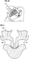
- Fig. 3h shows an embodiment of the shoe 100 having an upper 110 with a reinforcing element 140 arranged on the inside of the upper 110 .
- the reinforcing element 140 is provided as a webbing or mesh.
- the embodiment shown in Fig. 3h may be the same or similar to the embodiment shown in Figs. 3a -f.
- the shoe 100 can also be without a reinforcing element.
- the reinforcing element 140 can connect to or be integrated with a lacing system of the shoe 100 on the medial side 105 and the lateral side 102 of the instep.
- the reinforcing element 140 may also be separate from the lacing system. With the help of the lacing system, the foot of a wearer can be secured within the upper 110 of the shoe 100.
- the reinforcing element 140 may comprise a flexible yet highly tear resistant material.
- the material may be a textile material.
- the material may be a synthetic material.
- the material may be a synthetic hybrid material. Examples of potential materials are: polyurethane (PU), thermoplastic polyurethane (TPU), compact materials for example, polyamide (PA), polyethylene (PE), polypropylene (PP).
- the reinforcing element 140 may comprise a webbing.
- the reinforcing element 140 may comprise a stretchable webbing.
- the reinforcing element 140 may comprise a non-stretch webbing.
- the reinforcing element 140 may comprise a mesh. It will be apparent to the skilled person that other similar materials may be used that can perform the basic functionality described herein.
- the reinforcing element 140 may entirely or only partially be comprised of one or more of these kinds of materials.
- the reinforcing element 140 can be attached to the fabric of the upper 110 , for example, by printing, welding or sewing, and on the inside of the upper 110 as well as on the outside..
- the lateral and medial parts of the reinforcing element 140 are sewn together with the seam 118 in the region of the arch of the foot.
- the reason for this is that for the manufacture of the shoe 100 an initially flat-shaped blank similar to the blank 200 shown in Fig. 4 was trimmed and sewn up, as already mentioned. In this way, the upper 110 was given its three-dimensional shape.
- the blank 200 contains a reinforcing element 240, which, in the unconnected state of the blank 200 shown in Fig. 4 , comprise a separate lateral and medial partial region. Only once the blank 200 has been connected to produce its three-dimensional shape, for example by a seam along the arch of the foot, a connected reinforcing element corresponding to the reinforcing element 140 is created which extends from the medial side of the instep around the lower side of the upper and beneath the arch of the foot to the lateral side of the instep.
- the upper 110 of the shoe 100 further comprises a lacing element 150.
- the lacing element 150 can be made of leather so that it has a high degree of stability and tear-resistance.
- the lacing element extends from the heel region of the upper 110 to the lateral side 102 and to the medial side 105 of the instep and it connects to a lacing system of the shoe 100, which, in the case shown here, is provided as a shoe lace 190.
- the shoe lace 190 is threaded through the openings in the lacing element 150.
- the lacing element 150 is not connected to the sole unit 120 in the midfoot region of the shoe 100 in the embodiment shown here, such that the decoupling of the movements of the upper 110 from the sole unit 120 in the midfoot region is not impeded by the lacing element 150.
- the lacing element 150 is integrally provided as one piece and extends from the medial side 105 of the instep around the heel to the lateral side 102 of the instep. In these regions, the lacing element 150 is sewn up to the reinforcing element 140 to increase the stability of the upper 110 .
- other attachment means for attaching the lacing element 150 may be utilised.
- a heel counter 155 for a improved securing of the heel in the upper 110 is also integrated into the lacing element 150.
- the heel counter can help in preventing the foot from sliding and blisters from forming.
- the upper 110 is also three-dimensionally shaped to abut the back of the wearer's foot in the region of the Achilles' tendon.
- the upper 110 comprises a heel groove 158 in this region, which abuts the back of the wearer's foot.
- the shoe 100 further comprises an optional insole 160.
- the insole 160 is not connected to the upper 110 in the midfoot region. Instead, the insole 160 is connected to the upper 110 merely in the heel region and in a forefoot region of the foot. Consequently, the insole 160 can by and large move independently of the upper 110 , such that the insole 160 can be in contact with the bottom side of the foot during much of a gait cycle and the shoe 100 is particularly comfortable to wear.
- the sole unit 120 shown in Figs. 3e comprises a support element 170 in the midfoot region, which is a three-dimensionally shaped support element 170. It comprises two partial regions extending from the midfoot region to the heel region and the forefoot region of the midsole 122 and being at least partially embedded in the material of the midsole 122. The two partial regions are connected to each other in a connection region, so that they can be rotated against each other at least up to a certain locking angle. The connection region is arranged in a window 175 in the midsole so as not to impede this rotation.
- the support element 170 allows the bending stiffness of the sole unit 120 to be influenced and controlled independently of its torsional or twisting stiffness.
- the support element 170 can also enhance the ability of the sole unit 120 to limit overpronation and/or underpronation, to support the arch of the foot or to otherwise compensate for malposition or disadvantageous characteristic motion patterns of a wearer.
- the sole unit 120 of the shoe 100 comprises a midsole 122, which comprises particles of an expanded material.
- the particles can be randomly arranged and they can be connected to each other, for example at their surfaces.
- randomly arranged particles from expanded thermoplastic polyurethane (eTPU) were used, which were welded to each other by providing heat to their surfaces.
- the heat may, for example, be provided in the form of pressurized steam, for example, during steam chest molding, or electromagnetic radiation, or radio frequency radiation, or microwave radiation, or infrared radiation, or ultraviolet radiation, or electromagnetic induction.
- the particles may be connected to each other by providing heat energy provided by a combination of the methods of providing heat energy..
- the use of a binding agent is also conceivable.
- particles from expanded polyetherblockamide (ePEBA) and/or from expanded polyamide (ePA) may also be used.
- the sole unit 120 also comprises an outsole 180.
- the outsole 180 is provided in a net- or lattice-form to reduce the weight and still allow good traction of the shoe 100.
- material of the outsole 180 for example, thermoplastic polyurethane and / or rubber are possible.
- Fig. 3g shows an embodiment of the shoe 100 with a different sole unit 120 having a midsole 122 and an outsole 180, which does not comprise a support element.
- the embodiment shown in Fig. 3g may be the same or similar to the embodiment shown in Figs. 3a -f .
- Figs. 5a -c show a further embodiment of an inventive shoe 300.
- the statements made with regard to the shoe 100 analogously apply to the embodiment of a shoe 300. Therefore, those features of the shoe 300 which differ from the shoe 100 are predominantly discussed below.
- the shoe 300 comprises an upper 310 and a sole unit 320 , wherein the upper 310 is attached to the sole unit 320 such that in a midfoot region of the shoe 300 there is a gap 330 between a lower side of the upper 310 and a top side of the sole unit 320 .
- the shoe 300 comprises a reinforcing element 340 extending from a medial side of the instep around the lower side of the upper 310 and beneath the arch of the foot to a lateral side of the instep.
- the reinforcing element 340 connect to a lacing system of the shoe 300 , here the shoe lace 390 , on the medial and the lateral side of the instep.
- this connection is provided by the ends of the reinforcing element 340 comprising eyelets (loops or something similar are also conceivable) both on the lateral and the medial side of the instep through which a shoe lace 390 can be threaded.
- the reinforcing element 340 can be tightened around the midfoot region of the foot by tying up the shoe lace 390.
- the reinforcing element 340 is, at least partially, not fixedly connected to the upper 310 . Instead, the reinforcing element 340 can in parts move independently of the upper 310. In the embodiment show in Figs. 5a -c, the reinforcing element 340 is not fixedly connected to the upper 310 in the region of the lateral and medial instep. This can clearly be seen in Fig. 5b , in which the top of the reinforcing element 340 is pulled away from the upper 310 by hand.
- the reinforcing element 340 is made from leather and comprises a high stretch resistance. Further possible materials have already been named in the context of the discussion of the reinforcing element 140 and these materials may also be used for the reinforcing element 340.
- Figs. 6a -b show two further embodiments of an inventive shoe 500.
- the statements made with regard to the shoes 100 and 300 apply analogously to the shoe 500.
- the shoe 500 comprises an upper 510 and a sole unit 520 .
- the upper 510 is attached to the sole unit 520 such that in a midfoot region of the shoe 500 there is a gap between a lower side of the upper 510 and a top side of the sole unit 520.
- the shoe 500 does not comprise a reinforcing element in the adaptive region.
- the gap between the upper 510 and the sole unit 520 of an inventive shoe 500 can be covered on the medial and / or lateral side of the shoe 500 by a respective panel 512 of the upper 510.
- the panels 512 may prevent the ingress of stones, water or dirt into the gap.
- the gap still provides a degree of independence of movement between the upper 510 and the sole unit 520 despite the entrance to the gap being covered in this way.
- another implementation of forming a barrier to the ingress of matter could be employed, for example, a net or a foil could be used instead of the panels 512.
- the embodiment used should permit a degree of independence of movement between the sole and the lower part of the upper.
- Figs. 7a -c show an embodiment of a method 400 according to the invention for the manufacture of a shoe, for example the shoe 100 , 300 or 500.
- the method 400 comprises the following steps: First, an upper 410 , e.g. one of the uppers 110, 310 or 510 , is mounted on a last 401 . For example, the upper 410 is slid onto the last 401 .
- the upper 410 is then connected to a sole unit 420 , for example one of the sole units 120 , 320 or 520 , only in a forefoot region and a heel region, as indicated by the arrows 402 and 403 in Fig. 7a .
- the connection is effected in such a manner that in a midfoot region there is a gap 430 between a lower side of the upper 410 and a top side of the sole unit 420 , as shown in Fig. 7b .
- the last 401 comprises a concave shape 405 in the midfoot region.
- the shape 405 may be in correspondence with the arch of a foot of a wearer.
- the upper 410 can abut the last 401 in the midfoot region.
- the desired degree of predetermined tension can be imparted to the upper 410 in the manufactured shoe in order to achieve the desired fit.
- the amount of pre-tension imparted to the upper 410 in the manufacture of the shoe can also be adjusted and influenced by varying the ratio of the cross-sectional area of the last 401 in the region of the gap and the cross-sectional area of the foot of a wearer in the corresponding region.
- This concept is illustrated in Fig. 7c : With regard to a sectional plane A-A arranged in the midfoot region where the gap is located, and with the longitudinal direction (i.e. the direction from the heel to the toes) of the shoe being essentially perpendicular to the plane A-A, the last 401 comprises a smaller cross-sectional area than the foot, as shown in the left half of Fig. 7c .
- the cross-sectional area of the last 401 may for example be 0.8 times the cross-sectional area of an average foot, or 0.7 times the cross-sectional area of an average foot, or 0.6 times the cross-sectional area of an average foot, or 0.5 times the cross sectional area of an average foot.
- the sole unit 420 can comprise particles of expanded thermoplastic polyurethane (eTPU), and/or of expanded polyetherblockamide (ePEBA), and/or of expanded polyamide (ePA).
- the particles can be connected to each other, for example at their surfaces, and they can be randomly arranged.
- the connection of particles can be achieved during the method 400, for example by adding a binding agent.
- the particles are welded to each other during the method 400 by providing heat energy to them, for example in the form of steam.
- FIG. 8 shows a lateral side view 102 of another embodiment of a shoe 500 being similar to shoe 100 as described above.
- the shoe 500 comprises an upper 110 and a sole unit 120, wherein the upper 110 is attached to the sole unit 120 such that in a midfoot region of the shoe 500 there is a gap 130 between a lower side 115 of the upper 110 and a top side of the sole unit 120.
- the sole unit 120 may have a midsole 122 and an outsole 180.
- shoe 500 may comprise a lacing element 150.
- the midfoot region can be manufactured to be a piece providing a higher rigidity for an increased support of the arch of the wearer of the shoe.
- the other regions of the upper in the forefoot and/or the heel region may for example be more flexible and elastic to improve the wearing comfort.
- such regions may have a higher tensile strength to provide increased support for lateral sports such as tennis or hockey with many lateral movements of the foot.
Abstract
Description
- The present invention relates to a shoe, in particular a sports shoe, and a method for the manufacture thereof.
- Shoes, in particular sports shoes, usually comprise a shoe sole and a shoe upper.
- Shoe soles and shoe uppers typically serve multiple purposes in the overall design of a shoe, for example, one such purpose of the sole of the shoe is to protect the foot of the wearer from ingress of sharp objects into the plantar surface of the wearer's foot that otherwise may injure the wearer. Another such purpose of the sole and/or shoe upper is to control ground reaction forces acting on and through the musculoskeletal system of the wearer. In addition, the shoe upper in particular, must also provide a comfortable and safe environment for the foot of the wearer for the duration of time the wearer is using the shoe.
- However, the shoe must adapt to varying conditions over the duration of wear and also to the individual characteristics of the wearers and their musculoskeletal system during movement, for example, during a gait cycle. It is often a disadvantage of commonly available shoes that this adaptation of the shoe is not sufficient for all wearers.
- In this context
US 4,546,559 A1 discloses an athletic shoe, especially a running shoe, formed in such a way that a flexible running sole is provided only in the area of its running surface and, thus, largely does not exist in the area of the longitudinal arch of the foot. Additionally, the running sole has a supporting wall in this area that is fitted to the arch of the foot.US 3,586,003 A1 andUS 6,925,734 B1 relate to elements which can be placed in shoes for arch support.US 5,319,866 A1 as well as its UKcounterpart GB 2 258 801 A1 French counterpart FR 2 683 432 A1 - Therefore, a problem exists to provide a shoe with improved adaptation to both the musculoskeletal system of the wearer and the conditions encountered during use.
- The present invention seeks to provide an improved shoe, in particular and improved sports shoe, for example, a running shoe.
- The problem outlined above is at least partially solved by a shoe, according to
claim 1. In an embodiment, the shoe comprises an upper and a sole unit, wherein the upper is attached to the sole unit such that in a midfoot region there is a gap between a lower side of the upper and a top side of the sole unit. This region is also termed the "adaptive region". -
Fig. 1a illustrates the different regions of a shoe, including a heel region, the adaptive region in which the gap is located, and a forefoot region. The upper may be attached to the sole unit in the heel region and the forefoot region. - As a result of the gap between the lower side of the upper and the top side of the sole unit in the midfoot region, it is possible for the upper to move, essentially independently, of the sole unit in the midfoot region. Consequently, the upper can better adapt to the individual characteristics of the musculoskeletal system of the wearer and/or to the movements and forces the musculoskeletal system is subject to during movement of the wearer, for example, during a gait cycle. The independent movement of the upper may allow the upper to remain in close proximity to the foot of the wearer whilst the wearer is moving. This close proximity of the upper to the foot of the wearer may support or stimulate the musculoskeletal system so that the system is better equipped to handle the forces acting, for example, through stimulating the arch of the foot to engage the onward postural chain to avoid possible negative effects, for example, arch collapse, thus, increasing the stability of the foot and musculoskeletal system of the wearer. Furthermore, the gap can prevent or limit rubbing and chafing of the foot. The gap can also increase ventilation to the sole of the foot, consequently enabling a more comfortable environment for the foot of the wearer.
- There may be a connection between the upper and the sole unit in the adaptive region, namely in the region of the gap, the connection being provided in such a manner that the independence of movement of the shoe upper in the adaptive region is not significantly impeded. For example, the adaptive region may be covered on the sides of the shoe by a shoe panel, for example, comprised of mesh or foil. This can help to prevent the ingress of foreign matter, for example, stones or dirt into the gap. The ingress of foreign matter can be undesirable for a number of reasons, for example, a stone could protrude into the lower surface of the upper and press into the plantar region of the foot causing discomfort to the wearer. Alternatively the ingress of matter may ruin the visual appearance of the shoe in this region.
- The gap in the adaptive region may extend from a lateral side of the shoe to a medial side of the shoe.
- This can help to decouple the movements of the upper over the entire width of the shoe.
- The medial-lateral direction is shown in
Fig. 2 and is to be taken to be the direction in the arch area of the shoe to support and adapt to a foot shape. - The adaptive region consists of a region approximately over the midfoot of the wearer. As already mentioned, the upper may be attached to the sole unit in the heel region and the forefoot region. The heel region may be a minimum of 15% of the longitudinal shoe length from the rear of the shoe. The heel region may also be a minimum of 25% of the longitudinal shoe length from the rear of the shoe. The forefoot region may be a minimum of 20% of the longitudinal shoe length from the front of the shoe. The forefoot region may also be a minimum of 40% of the longitudinal shoe length from the front of the shoe.
- The gap may have a longitudinal extension of at least 2 cm, at least 5 cm, at least 10 cm, at least 15 cm, at least 20 cm of a UK size 8.5 sample size shoe. For a UK size 8.5 sample size shoe, the gap may be in the range of 2 cm to 10 cm.
- It will be apparent to the skilled person that the desired gap extension will vary dependent upon the shoe size chosen for the wearer, for example, a UK
size 12 is approximately 32 cm in total length whereas a UK size 6 is approximately 23 cm in length. Clearly the skilled person will realise that the desired gap extension chosen will need to be scaled up or down dependent upon the size of the shoe. - A gap with such a longitudinal extension provides a good compromise between independence of the movement of the upper on the one hand, and ensuring sufficient stability of the shoe upper on the sole unit on the other hand.
- The gap may extend essentially over the length of the arch of a foot of a wearer.
- The plantar region of the foot, and in particular the arch of a foot, is subject to significant movement and forces during wearer movement, for example, during a gait cycle. A gap extending essentially along the length of the wearer's arch can promote stability of the musculoskeletal system and/or enhance the ability of the musculoskeletal system to react to the forces incurred. The arch of a foot is also a sensitive part of the foot, thus, the upper to extend essentially over the length of the arch of the foot is advantageous for the comfort of the shoe for the wearer.
- It is possible that in the midfoot region the lower side of the upper has a shape configured to adapt to a lower side of the arch of the foot of the wearer.
- As a result, the fit of the upper can be improved, thus, further increasing the aforementioned stabilization and engagement effect. Through three-dimensionally pre-shaping the upper such that the shape of the upper is configured to adapt to the lower side of the arch of the foot, the arch can be particularly well ventilated, thus enhancing the comfort of the wearer in this region of the foot.
- In the midfoot region where the gap is located, i.e. in the adaptive region, the upper may be configured to allow a minimum strain of 5% in both the medial-lateral direction and the forefoot-to-rearfoot direction (longitudinally along the shoe). As already stated above, the medial-lateral direction is illustrated in
Fig. 2 and is to be taken to be the direction in the arch area of the shoe to support and adapt to a foot shape. In the midfoot region where the gap is located, i.e. in the adaptive region, the upper may be configured to allow a maximum strain of 150% in both the medial-lateral direction and the forefoot-to-rearfoot direction (longitudinally along the shoe). The forefoot-to-rearfoot direction can also be called the anterior-to-posterior direction. The strain may in part be comprised of a strain imparted to the upper during manufacture of the upper. The strain may in part be imparted when the user inserts their foot into the upper. The strain may be imparted during use of the shoe by the wearer. Sufficient flexibility of the upper can allow the upper to closely abut the foot of a wearer and hence adapt to the movement and contours of the foot. - The material of the upper may comprise an elastic content. The material of the upper may comprise or be comprised of any material that can perform the stated performance criteria, examples of such materials are: any knitted material, a natural material, a synthetic material, synthetic fibres, synthetic leather, thermoplastic polyurethane (TPU), leather, cotton. Further, the material of the upper may comprise elastane fibres, for example, Lycra which is manufactured under trademark by Invista under licence from Koch, formerly part of DuPont.
- By using elastane fibres, in particular Lycra fibres, the upper provided can be flexible but also tear-resistant.
- The upper may comprise a different material in the midfoot region than in the heel region and/or in the forefoot region, wherein the different material may preferably be restricted to the lower side of the upper above the gap.
- As a result, the material in the midfoot region may be specifically manufactured to provide certain stretch and/or support characteristics for the adaptive region. Using a different material can also allow for tailoring of the remaining regions of the upper to other desired characteristics of these regions.
- The upper may be a knitted upper. The knitted upper may be a circular knitted upper. The knitted upper may be a flat knit upper. The knitted upper may be a warp knit. The upper may be an engineered mesh. The upper may also be only partially comprised of one or more of these kinds of materials.
- The lower side of the upper, in particular, in the midfoot region, may be seamless.
- This can facilitate comfort for the wearer of the shoe since the region of the arch of the foot is free from areas that may promote rubbing, chafing or pressure points in these sensitive regions of the foot. Furthermore, the lack of any seam in these regions can increase the stability, tear-resistance and fit of the upper.
- It is also possible for the entire upper to be seamless. The seamless upper may, for example, be provided by circular knitting.
- A circular knit upper can allow a three-dimensionally preshaped upper to be provided without an upper blank having to be sewn up at a designated place(s). Thus, unwanted seams in the upper can be avoided and the three-dimensionally preshaped upper can have a particularly good fit and the additional aforementioned benefits of a seamless midfoot region.
- The upper may encompass the arch of the foot of the wearer. Furthermore, particularly in the region of the gap, the upper may abut the foot of the wearer on all sides of the foot. This may be achieved by using a lacing system.
- A lacing system can be used to tie in or secure the foot of a wearer within the shoe upper. The lacing system can, for example, comprise a shoe lace, or it can comprise a shoe lace and a cord lock, or it can comprise a hook and loose fastener or any other means known in the art for tying in the foot of a wearer.
- As a result of the arch of the foot being encompassed by the upper, the advantageous effects indicated above can be further improved. In particular, a particularly comfortable feel and good stabilization and engagement of the foot and onward musculoskeletal system can be achieved.
- The upper can have at least one reinforcing element extending from a medial side of the instep around the lower side of the upper to the lateral side of the foot. The reinforcing element can, for example, be arranged on the outside of the upper, or on the inside of the upper, or be integrated within the upper.
- The reinforcing element can serve the purpose of increasing the stabilisation and engagement of the foot in the upper, assisting in stabilising the musculoskeletal system of the wearer. The reinforcing element may be additional to the stability and reinforcement of the upper in the adaptive region. The reinforcing element may be used in conjunction with the upper to provide the desired performance in the adaptive region.
- The reinforcing element can connect to or be integrated with a lacing system of the shoe on the medial and the lateral side of the instep. The reinforcing element may also be separate from the lacing system.
- The reinforcing element may comprise a flexible yet highly tear resistant material. The material may be a textile material. The material may be a synthetic material. The material may be a synthetic hybrid material. Examples of potential materials are: polyurethane (PU), thermoplastic polyurethane (TPU), compact materials for example, polyamide (PA), polyethylene (PE), polypropylene (PP). The reinforcing element may comprise a webbing. The reinforcing element may comprise a stretchable webbing. The reinforcing element may comprise a non-stretch webbing. The reinforcing element may comprise a mesh. It will be apparent to the skilled person that other similar materials may be used that can perform the basic functionality described herein. The reinforcing element may entirely or only partially be comprised of one or more of these kinds of materials.
- A flexible and tear resistant material is particularly suitable for such a reinforcing element, as it will enable a balance between free movement of the upper to allow the aforementioned benefits but also control the stretchability and upper movement which can allow improvements in the aforementioned comfort and stability benefits and / or a tailoring of the resultant properties of the adaptive region for different designs / uses of a shoe incorporating it.
- The reinforcing element can be attached to the fabric of the upper, for example, by printing, welding or sewing.
- By attaching the reinforcing element to the outer side of the fabric, seams or other unwanted connecting regions that could rub on the foot of the wearer and thus make the shoe less comfortable to wear can be avoided. Also, a potential tearing of the reinforcing element and the upper in such connecting regions under high load can be avoided. Attaching the reinforcing element to the upper also enables manufacturing processes to be more efficient. For example, it would be possible to streamline a process to use the same uppers but apply different reinforcing materials to create shoes with varying degrees of reinforcement.
- The reinforcing element may be incorporated into the material of the upper in the midfoot region by increasing the strength and density of the upper material in this region. The reinforcing element may have greater reinforcing properties on the medial side compared with the lateral side.
- The benefits of incorporating the reinforcing element are as those stated earlier and additionally that the process of manufacture is simplified, thus, reducing complexity and cost.
- It is possible for the upper to comprise a lacing element extending from a heel region to the lateral side and/or medial side of the instep and connecting to the lacing system of the shoe. The lacing element may not be connected to the sole unit in the midfoot region.
- With such a lacing element, the heel region of a foot of a wearer can be firmly secured to the upper and the strength and stability of the upper in the heel region can be increased, which can be desirable to prevent injuries caused by twisting one's ankle. The lacing element can be formed from a tear-resistant material, for example leather, and it can cooperate with the lacing system to allow for tight lacing of the upper. Not connecting the lacing element to the sole unit can be advantageous as there is no restricting connection between the upper and the sole in the region of the midfoot, thus, this will not interfere with the independent movement of the upper.
- The lacing element may be integrally provided as one piece and extend from the medial side of the instep around the heel to the lateral side of the instep.
- With a lacing element that is integrally provided as one piece, the overall stability of the upper can be further improved and it can also simplify the manufacture of the shoe since less individual parts need to be processed.
- It is also possible that, in the heel region, the upper is three-dimensionally shaped to abut the back of the wearer's foot in the region of the Achilles' tendon. In combination with the gap in the midfoot region, an upper provided in this manner may beneficially be used to better lock in the foot while still maintaining sufficient adaptivity of the upper. Also, the fit of the upper in the heel region can be generally improved. In particular rubbing of the upper at the Achilles' tendon can be prevented. Such rubbing can lead to extremely unpleasant irritations, particularly during dynamic movements such as occur when walking or running.
- The shoe can comprise an insole, which is not connected to the upper in the midfoot region.
- With such an insole, which is not connected to the upper in the midfoot region, the shoe can again be made more comfortable to wear. It may allow the insole to abut the bottom of the foot of a wearer during the entire gait cycle, thus providing for a consistently pleasant wearing sensation.
- The insole may be connected to the upper in the heel region and the forefoot region of the shoe but free in the midfoot region of the shoe. The insole may comprise a "bone-like" shape akin to the surface impression a footprint leaves on the ground.
- Such an insole can provide a design that is adjusted to the anatomy of the foot. Consequently, the stress on the foot can be reduced to prevent injuries and to facilitate endurance.
- The sole unit can comprise particle(s) of expanded material, in particular, expanded thermoplastic polyurethane (eTPU), and/or expanded polyetherblockamide (ePEBA), and/or expanded polyamide (ePA). The particles may be randomly arranged. The particles may also be connected to each other, for example, at their surfaces. The particles may be connected to each other by providing heat energy provided by pressurized steam, for example, during steam chest molding, or electromagnetic radiation, or radio frequency radiation, or microwave radiation, or infrared radiation, or ultraviolet radiation, or electromagnetic induction. The particles may be connected to each other by providing heat energy provided by a combination of the methods of providing heat energy. The particles may be connected to each other by steam molding. The particles may be connected to each other by use of a binding agent. Alternatively or additionally, the particles may be connected to each other by using a combination of the aforementioned methods. It is to be understood that expanded particles are to be interpreted in the context of the field of particle foams, namely, that the particle has already been expanded or "foamed" prior to being placed within the mold. Therefore, the resulting particle foam component is comprised of a plurality of individual particle foam beads, each bead having already been foamed (to a level that establishes the properties of the foam) prior to be formed into the final component. For example, expanded TPU beads are placed in the mold and then a chemical reaction occurs to form the resulting particle foam components. It should be noted that there are a number of synonymous terms used within the art that describe the same concept, for example, "foamed bead(s)", "foamed pellet(s)", "particle foams" to name just some.
- A sole unit comprising expanded particles, i.e. particle foam, can provide good cushioning properties over a wide temperature range. At the same time, sole units with such particles can return a large share of the energy exerted to deform the sole during impact back to the foot when the sole expands again later in the gait cycle. This can facilitate efficiency in walking or running and thus increase the endurance of the wearer. The particles can be randomly arranged which might facilitate ease of manufacture. Alternatively, a conventional ethylene-vinylacetate (EVA) or any other shoe sole could be used, and also sole units with combinations of particles from expanded materials and other materials, for example, EVA, eTPU, ePEBA and/or ePA are possible.
- The sole unit may comprise a support element, in particular to enhance the ability to limit overpronation and/or underpronation. The support element can be arranged in the midfoot region.
- With such an additional support element, the stress on the foot can be further relieved. This can further help in stabilising the foot and musculoskeletal system of the wearer and aid in preventing injuries or fatigue.
- The support element can also serve to adjust the bending stiffness and/or torsional stiffness of the sole unit in the midfoot region. The support element can, for example, be embedded in the material of the sole unit.
- A further aspect of the invention is given by a method for the manufacture of a shoe, in particular a sports shoe like a running shoe, comprising the following steps: Mounting an upper on a last and connecting the upper to a sole unit only in a forefoot region and a heel region, such that in a midfoot region there is a gap between a lower side of the upper and a top side of the sole unit.
- In embodiments of such an inventive method, it is possible to combine the optional design possibilities for an inventive shoe discussed above in various combinations and thus adjust the properties of the manufactured shoe to the respective requirements during manufacture.
- The last may comprise a concave shape in the midfoot region, wherein, during the step of connecting, the upper abuts the last in the midfoot region. The concave shape may be in correspondence with the arch of a foot of a wearer.
- As a result of the upper being mounted during the method on a last, whose shape may be in correspondence with the arch of the foot, undesired distortions or deformations of the upper can be prevented. The upper can be mounted on the last "under tension" so that it abuts the last in a form-fit manner.
- The shape, dimensions and configuration of the concave region of the last may be adjusted to control and influence the degree of tension imparted to the resultant upper in the midfoot region.
- The last may comprise a smaller cross-sectional area than the foot of a wearer with respect to a sectional plane arranged in the midfoot region where the gap is located and with the longitudinal direction of the shoe being essentially perpendicular to the sectional plane. The cross-sectional area of the last may for example be less than 80% of the corresponding cross-sectional area of the average foot (for example measured when the foot is inserted into the finished shoe), or less than 70% or less than 60%, or less than 50%.
- It is further possible for the sole unit to comprise particles of an expanded material, in particular of expanded thermoplastic polyurethane (eTPU), and/or of expanded polyetherblockamide (ePEBA), and/or of expanded polyamide (ePA). The particles may be randomly arranged. The particles may also be connected to each other.
- The advantageous properties of these materials for use in a sole unit have already been described above.
- Possible embodiments of the present invention are described in the following detailed description, with reference to the following Figures:
- Figs. 1a-b:
- Illustration of the different regions of an inventive shoe and exemplary dimensions of these regions;
- Fig. 2:
- Illustration of the term "medial-lateral direction";
- Figs. 3a-h:
- An embodiment of a shoe according to the invention;
- Fig. 4:
- An embodiment of a blank for an upper for use in a shoe according to the invention;
- Figs. 5a-c:
- A further embodiment of a shoe according to the invention;
- Figs. 6a-b:
- Further embodiments of an inventive shoe;
- Figs. 7a-c:
- An embodiment of a manufacturing method according to the invention;
- Fig. 8:
- A further embodiment of a shoe according to the present invention.
- Possible embodiments of the present invention are described in the following detailed description mainly in relation to running shoes. However, emphasis is placed on the fact that the present invention is not limited to these embodiments. Instead, it can also be applied to other types of shoes, such as sports shoes in general, leisure shoes, etc.
- It is also to be noted that only individual embodiments of the invention are described in greater detail below. However, it is clear to the person skilled in the art that the design possibilities described in relation to these specific embodiments can also be further modified and combined in a different manner with one another within the scope of the present invention and that individual features can also be omitted where they appear to be unnecessary. In order to avoid repetition, reference is made to the explanations in the previous sections, which also remain applicable to the following detailed description.
-
Figs. 3a -f show an embodiment of ashoe 100 according to the invention.Fig. 3a shows theshoe 100 in a top view.Fig. 3b shows a lateral side view andFig. 3c shows a medial side view of theshoe 100.Fig. 3d shows theshoe 100 from the back andFig. 3e shows a bottom view of theshoe 100.Fig. 3f shows an enlarged picture of the inside of the upper 110 of theshoe 100 with the insole removed. - The
shoe 100, which may be used as a running shoe, comprises an upper 110 and asole unit 120. Here, the upper 110 is attached to thesole unit 120 such that in a midfoot region of theshoe 100 there is agap 130 between alower side 115 of the upper 110 and atop side 125 of thesole unit 120. - In the
shoe 100, thegap 130 extends from alateral side 102 of theshoe 100 to amedial side 105 of theshoe 100. This means that thegap 130 extends over the entire width of theshoe 100. This can be seen inFig. 3b showing thelateral side 102 of theshoe 100 andFig. 3c showing themedial side 105 of theshoe 100. Here it can be seen that thegap 130 between thelower side 115 of the upper 110 and thetop side 125 of thesole unit 120 in the midfoot region extends from thelateral side 102 to themedial side 105 of thesole unit 120. In theshoe 100, there is no connection between the upper 110 and thesole unit 120 in the region of thegap 130. - In the embodiment shown in
Figs. 3a -f, thegap 130 comprises a longitudinal extension, i.e. an extension in the direction from the heel to the tips of the toes of the foot. - By way of example,
Fig. 1a shows an embodiment of aninventive shoe 10. The longitudinal extension of the gap in theshoe 10 shown inFig. 1a and other embodiments is dependent on the desired degree of decoupling of the upper from the sole unit. The desired degree of decoupling of the upper from the sole unit may be based upon at least one of a range of factors, for example: the desired tension in the midfoot region, the desired extension of the gap in relation to the upper, or the average size of a wearer's foot or a wearer's arch length or any combination thereof. Furthermore, the longitudinal extension of the gap will also be dependent on the selected shoe size. -
Fig. 1a also illustrates the different regions of aninventive shoe 10, namely aforefoot region 20, the midfoot region where the gap between the upper and the sole unit is located and which is also called theadaptive region 30, and aheel region 40. The upper may be attached to the sole unit in theheel region 40 and in theforefoot region 20. The skilled person will realise that these regions can analogously be defined for other embodiments of an inventive shoe. - Exemplary dimensions for three samples of an
inventive shoe 10 of size UK 5.5 are listed in the table ofFig. 1b . For example,sample # 1 has an overall length of 265 mm. The length of theadaptive region 30 is 75 mm (on the medial side) which is 28% of the overall length ofsample # 1. Theheel region 40 is 75 mm (on the medial side) which is 28% of the overall length ofsample # 1. Theforefoot region 20 is 115 mm (on the medial side) which is 43% of the overall length ofsample # 1. - Clearly the skilled person will realise that the desired gap
adaptive region 30 and therefore gap length will have to be scaled up or down for different size shoes, for example, scaled up for a UK size 16 and scaled down for a UK size 4. The minimum length of theforefoot region 20 is 15% of the overall length of theshoe 10. The minimum length of theheel region 40 is 20% of the overall length of theshoe 10. Depending on the size of theshoe 10, the gap may have a longitudinal extension of up to 20 cm, for example a longitudinal extension in the range from 2 cm - 10 cm. The gap may for example extend essentially over the length of the arch of a foot of a wearer having the respective shoe size. The considerations put forth with regard toFigs. 1a -b may also apply to other embodiments of an inventive shoe, like the embodiments ofinventive shoes - Returning to the discussion of
Figs. 3a -f, these figures show that the upper 110 encompasses the arch of the foot of the wearer. In other words, the upper extends from thelateral side 102 of the shoe along thegap 130 to themedial side 105 of theshoe 100. In the midfoot region, thelower side 115 of the upper 110 has a shape configured to adapt to the lower side of the arch of the foot of a wearer. In other embodiments the upper need not fully encompass the arch of a foot. As the upper 110 comprises a degree of elasticity and is decoupled from thesole unit 120 in the midfoot region, the upper 110 adapts, in terms of its shape, to the individual characteristics of the musculoskeletal system of the wearer and/or to the movements and forces the musculoskeletal system is subject to and/or the movements a foot of a wearer undergoes during movement of the wearer, for example, during a gait cycle. - In the midfoot region where the
gap 130 is located, i.e. in the adaptive region, the upper 110 may be configured to allow a minimum strain of 5% in both the medial-lateral direction and forefoot-to-rearfoot direction (also called the anterior-to-posterior direction). The allowed minimum strain may also be 10% or 15% or 20% or 30% or 50%. In the midfoot region where the gap is located, i.e. in the adaptive region, the upper 110 may be configured to allow a maximum strain of 150% in both the medial-lateral direction and forefoot-to-rearfoot direction. The allowed maximum strain may also be 125% or 110% or 100% or 80%. The medial-lateral direction is illustrated inFig. 2 for thesample shoe 10 which is also shown inFig. 1a . The medial-lateral direction is to be taken to be the direction from themedial side 15 to thelateral side 12 in the arch area of theshoe 10 to support and adapt to a foot shape. Again, these considerations may also apply to other embodiments of an inventive shoe, like the embodiments ofinventive shoes - The strain may in part be comprised of a strain imparted to the upper 110 during manufacture of the upper 110. The strain may in part be imparted when the user inserts their foot into the upper 110. The strain may be imparted during use of the
shoe 100 by the wearer. The strain may in part be imparted to the adaptive region by a combination of strain imparted in manufacture and during insertion of the foot of a wearer and during use. - To illustrate with an example, uppers comprising a material that can be stretched in all four directions (front or anterior, rear or posterior, medial, lateral) were tested and allowed a minimum strain of 60% under a load of 100N/cm in a warp direction of the mesh, and a minimum strain of 130% in a weft direction of the mesh. The weft direction of the mesh is aligned to allow the stretch in the medial and lateral directions. The above mentioned load of 100 N/cm refers to laboratory test method for material testing where a strip of mesh approximately 2.54 cm wide is tested. The strain values stated above are based on an internal laboratory test method which is why the strain values are much higher than the values stated with regard to the upper, as the forces acting during running are lower than the recited test values in the laboratory.
- An FEA (Finite Element Analysis) virtual simulation study was conducted that showed that the strain when the material is pulled over the last was on average 50%-60% in the adaptive region with a maximum of 92% at the midfoot seam. Once the last was removed from the upper some of this strain imparted by the last is removed whilst some is retained in the final shoe upper. The amount of strain retained will be dependent on the material used for the upper.
- To evaluate the performance of the shoe during use, testing was performed using an Aramis system from GOM mbH. The system is a calibrated digital image correlation (DIC) device which allows for dynamic real time surface strain measurement. The results found that the materials selected for the upper strained 6-14% under the load of the bodyweight of the wearer. Further strain was seen when the wearer was running, an average material strain being 20% with a maximum strain of 48% in the medial midfoot region. It will be apparent to the skilled person that the values quoted are testing values for the specific examples. The values will change depending upon the type of movement being performed and also the individual user.
- The material of the upper 110 may comprise an elastic content. The material may comprise or be comprised of any material that can perform the stated performance criteria, examples of such materials are: any knitted material, a natural material, a synthetic material, synthetic fibres, synthetic leather, thermoplastic polyurethane (TPU), leather, cotton. Further, the material of the upper 110 may comprise elastane fibres, for example, Lycra which is manufactured under trademark by DuPont.
- The upper 110 may be a knitted upper. The knitted upper may be a circular knitted upper. The knitted upper may be a flat knit upper. The knitted upper may be a warp knit. The upper 110 may be an engineered mesh. The upper 110 may also be only partially comprised of one or more of these kinds of materials.
- In the embodiment of a
shoe 100 shown inFigs. 3a -f, the upper 110 is manufactured by means of a blank by being trimmed and then sewn up (or otherwise connected) in certain places. An example of such a blank is the blank 200 shown inFig. 4 . As a result of the connection process, the upper 110 is provided with a three-dimensional shape. By a suitable design of the blank, the desired three-dimensional shape of the upper 110, in particular in the region of the arch of the foot, can be achieved. - In the embodiment shown in
Fig. 3f , the manufacture of the upper 110 has resulted in thelower side 115 of the upper 110 comprising aseam 118 which extends in the longitudinal direction over thelower side 115 and in particular over the region of the arch of the foot. - However, in other embodiments, the lower side of the upper 110 can be without a seam in the midfoot region. As already mentioned, the upper 110 can for example be provided in the midfoot region by circular knitting- or even the entire upper 110 can be provided by circular knitting. Circular knitting can allow providing a three-dimensionally shaped textile component without a seam. Further alternatives to circular knitting could be: 3D formed uppers (e.g. 3D printed uppers), overinjected textiles, molded materials, injected materials or vacuum formed materials.
- In the midfoot region, the upper 110 of the
shoe 100 can comprise a reinforcingelement 140. Any number (e.g. one, two, three, four, five, etc.) of reinforcing elements and / or reinforcing elements with different widths than shown here are also possible. The reinforcingelement 140 extends from themedial side 105 of the instep around thelower side 115 of the upper 110 and beneath the arch of the foot to thelateral side 102 of the instep. - The reinforcing
element 140 can, for example, comprise thermoplastic polyurethane, which may be welded to the fabric of the upper 110 on the outside of the upper 110 as shown inFigs. 3b -c. - The reinforcing element can also be arranged on the inside of the upper 110 or be integrated within the upper 110.
- By way of example,
Fig. 3h shows an embodiment of theshoe 100 having an upper 110 with a reinforcingelement 140 arranged on the inside of the upper 110. Here, the reinforcingelement 140 is provided as a webbing or mesh. Apart from that, the embodiment shown inFig. 3h may be the same or similar to the embodiment shown inFigs. 3a -f. - Moreover, the
shoe 100 can also be without a reinforcing element. - The reinforcing
element 140 can connect to or be integrated with a lacing system of theshoe 100 on themedial side 105 and thelateral side 102 of the instep. The reinforcingelement 140 may also be separate from the lacing system. With the help of the lacing system, the foot of a wearer can be secured within the upper 110 of theshoe 100. - The reinforcing
element 140 may comprise a flexible yet highly tear resistant material. The material may be a textile material. The material may be a synthetic material. The material may be a synthetic hybrid material. Examples of potential materials are: polyurethane (PU), thermoplastic polyurethane (TPU), compact materials for example, polyamide (PA), polyethylene (PE), polypropylene (PP). The reinforcingelement 140 may comprise a webbing. The reinforcingelement 140 may comprise a stretchable webbing. The reinforcingelement 140 may comprise a non-stretch webbing. The reinforcingelement 140 may comprise a mesh. It will be apparent to the skilled person that other similar materials may be used that can perform the basic functionality described herein. The reinforcingelement 140 may entirely or only partially be comprised of one or more of these kinds of materials. - The reinforcing
element 140 can be attached to the fabric of the upper 110, for example, by printing, welding or sewing, and on the inside of the upper 110 as well as on the outside.. - In the case of the embodiment of the
shoe 100 shown inFigs. 3b -c, the lateral and medial parts of the reinforcingelement 140 are sewn together with theseam 118 in the region of the arch of the foot. The reason for this is that for the manufacture of theshoe 100 an initially flat-shaped blank similar to the blank 200 shown inFig. 4 was trimmed and sewn up, as already mentioned. In this way, the upper 110 was given its three-dimensional shape. - As can be seen in
Fig. 4 , the blank 200 contains a reinforcingelement 240, which, in the unconnected state of the blank 200 shown inFig. 4 , comprise a separate lateral and medial partial region. Only once the blank 200 has been connected to produce its three-dimensional shape, for example by a seam along the arch of the foot, a connected reinforcing element corresponding to the reinforcingelement 140 is created which extends from the medial side of the instep around the lower side of the upper and beneath the arch of the foot to the lateral side of the instep. - An advantage of this approach is that the reinforcing
element 240, which is not yet connected in the unconnected state of the blank 200, can be particularly well printed on, welded or otherwise applied to the blank 200. In the case of an already three-dimensionally preshaped blank, this could be more difficult or involve greater expense. - Returning to the discussion of the embodiment of a
shoe 100 shown inFigs. 3a -f, the upper 110 of theshoe 100 further comprises alacing element 150. Thelacing element 150 can be made of leather so that it has a high degree of stability and tear-resistance. The lacing element extends from the heel region of the upper 110 to thelateral side 102 and to themedial side 105 of the instep and it connects to a lacing system of theshoe 100, which, in the case shown here, is provided as ashoe lace 190. Theshoe lace 190 is threaded through the openings in thelacing element 150. It is to be noted that thelacing element 150 is not connected to thesole unit 120 in the midfoot region of theshoe 100 in the embodiment shown here, such that the decoupling of the movements of the upper 110 from thesole unit 120 in the midfoot region is not impeded by thelacing element 150. - For the
shoe 100, thelacing element 150 is integrally provided as one piece and extends from themedial side 105 of the instep around the heel to thelateral side 102 of the instep. In these regions, thelacing element 150 is sewn up to the reinforcingelement 140 to increase the stability of the upper 110. However, it will be clear to the skilled person that other attachment means for attaching thelacing element 150 may be utilised. - A
heel counter 155 for a improved securing of the heel in the upper 110 is also integrated into thelacing element 150. The heel counter can help in preventing the foot from sliding and blisters from forming. In the heel region, the upper 110 is also three-dimensionally shaped to abut the back of the wearer's foot in the region of the Achilles' tendon. To this end, the upper 110 comprises aheel groove 158 in this region, which abuts the back of the wearer's foot. - The
shoe 100 further comprises anoptional insole 160. Theinsole 160 is not connected to the upper 110 in the midfoot region. Instead, theinsole 160 is connected to the upper 110 merely in the heel region and in a forefoot region of the foot. Consequently, theinsole 160 can by and large move independently of the upper 110, such that theinsole 160 can be in contact with the bottom side of the foot during much of a gait cycle and theshoe 100 is particularly comfortable to wear. - The
sole unit 120 shown inFigs. 3e comprises asupport element 170 in the midfoot region, which is a three-dimensionally shapedsupport element 170. It comprises two partial regions extending from the midfoot region to the heel region and the forefoot region of themidsole 122 and being at least partially embedded in the material of themidsole 122. The two partial regions are connected to each other in a connection region, so that they can be rotated against each other at least up to a certain locking angle. The connection region is arranged in awindow 175 in the midsole so as not to impede this rotation. Thesupport element 170 allows the bending stiffness of thesole unit 120 to be influenced and controlled independently of its torsional or twisting stiffness. - The
support element 170 can also enhance the ability of thesole unit 120 to limit overpronation and/or underpronation, to support the arch of the foot or to otherwise compensate for malposition or disadvantageous characteristic motion patterns of a wearer. - The
sole unit 120 of theshoe 100 comprises amidsole 122, which comprises particles of an expanded material. The particles can be randomly arranged and they can be connected to each other, for example at their surfaces. For theshoe 100, randomly arranged particles from expanded thermoplastic polyurethane (eTPU) were used, which were welded to each other by providing heat to their surfaces. The heat may, for example, be provided in the form of pressurized steam, for example, during steam chest molding, or electromagnetic radiation, or radio frequency radiation, or microwave radiation, or infrared radiation, or ultraviolet radiation, or electromagnetic induction. The particles may be connected to each other by providing heat energy provided by a combination of the methods of providing heat energy.. The use of a binding agent is also conceivable. In addition, particles from expanded polyetherblockamide (ePEBA) and/or from expanded polyamide (ePA) may also be used. - The
sole unit 120 also comprises anoutsole 180. In the present case, theoutsole 180 is provided in a net- or lattice-form to reduce the weight and still allow good traction of theshoe 100. As material of theoutsole 180, for example, thermoplastic polyurethane and / or rubber are possible. - Finally, it is mentioned that the
sole unit 120 need not necessarily comprise a support element. By way of example,Fig. 3g shows an embodiment of theshoe 100 with a differentsole unit 120 having amidsole 122 and anoutsole 180, which does not comprise a support element. Apart from that, the embodiment shown inFig. 3g may be the same or similar to the embodiment shown inFigs. 3a -f. -
Figs. 5a -c show a further embodiment of aninventive shoe 300. The statements made with regard to theshoe 100 analogously apply to the embodiment of ashoe 300. Therefore, those features of theshoe 300 which differ from theshoe 100 are predominantly discussed below. - The
shoe 300 comprises an upper 310 and asole unit 320, wherein the upper 310 is attached to thesole unit 320 such that in a midfoot region of theshoe 300 there is agap 330 between a lower side of the upper 310 and a top side of thesole unit 320. - The
shoe 300 comprises a reinforcingelement 340 extending from a medial side of the instep around the lower side of the upper 310 and beneath the arch of the foot to a lateral side of the instep. The reinforcingelement 340 connect to a lacing system of theshoe 300, here theshoe lace 390, on the medial and the lateral side of the instep. In the embodiment shown inFigs. 5a -c, this connection is provided by the ends of the reinforcingelement 340 comprising eyelets (loops or something similar are also conceivable) both on the lateral and the medial side of the instep through which ashoe lace 390 can be threaded. Thus, the reinforcingelement 340 can be tightened around the midfoot region of the foot by tying up theshoe lace 390. - Unlike the reinforcing
element 140, the reinforcingelement 340 is, at least partially, not fixedly connected to the upper 310. Instead, the reinforcingelement 340 can in parts move independently of the upper 310. In the embodiment show inFigs. 5a -c, the reinforcingelement 340 is not fixedly connected to the upper 310 in the region of the lateral and medial instep. This can clearly be seen inFig. 5b , in which the top of the reinforcingelement 340 is pulled away from the upper 310 by hand. - In the embodiment shown in
Figs. 5a -c, the reinforcingelement 340 is made from leather and comprises a high stretch resistance. Further possible materials have already been named in the context of the discussion of the reinforcingelement 140 and these materials may also be used for the reinforcingelement 340. -
Figs. 6a -b show two further embodiments of aninventive shoe 500. The statements made with regard to theshoes shoe 500. - The
shoe 500 comprises an upper 510 and asole unit 520. The upper 510 is attached to thesole unit 520 such that in a midfoot region of theshoe 500 there is a gap between a lower side of the upper 510 and a top side of thesole unit 520. - In the embodiment shown in
Fig. 6a , theshoe 500 does not comprise a reinforcing element in the adaptive region. - As shown in
Fig. 6b , the gap between the upper 510 and thesole unit 520 of aninventive shoe 500 can be covered on the medial and / or lateral side of theshoe 500 by arespective panel 512 of the upper 510. Thepanels 512 may prevent the ingress of stones, water or dirt into the gap. However, it should be noted that the gap still provides a degree of independence of movement between the upper 510 and thesole unit 520 despite the entrance to the gap being covered in this way. Alternatively, another implementation of forming a barrier to the ingress of matter could be employed, for example, a net or a foil could be used instead of thepanels 512. Again it is stressed that the embodiment used should permit a degree of independence of movement between the sole and the lower part of the upper. -
Figs. 7a -c show an embodiment of amethod 400 according to the invention for the manufacture of a shoe, for example theshoe method 400 comprises the following steps: First, an upper 410, e.g. one of theuppers sole unit 420, for example one of thesole units arrows Fig. 7a . The connection is effected in such a manner that in a midfoot region there is agap 430 between a lower side of the upper 410 and a top side of thesole unit 420, as shown inFig. 7b . - In the embodiment shown in
Figs. 7a -c, the last 401 comprises aconcave shape 405 in the midfoot region. Theshape 405 may be in correspondence with the arch of a foot of a wearer. - During the connecting, the upper 410 can abut the last 401 in the midfoot region. With a suitable design of the
concave region 405 of the last 401, the desired degree of predetermined tension can be imparted to the upper 410 in the manufactured shoe in order to achieve the desired fit. - The amount of pre-tension imparted to the upper 410 in the manufacture of the shoe can also be adjusted and influenced by varying the ratio of the cross-sectional area of the last 401 in the region of the gap and the cross-sectional area of the foot of a wearer in the corresponding region. This concept is illustrated in
Fig. 7c : With regard to a sectional plane A-A arranged in the midfoot region where the gap is located, and with the longitudinal direction (i.e. the direction from the heel to the toes) of the shoe being essentially perpendicular to the plane A-A, the last 401 comprises a smaller cross-sectional area than the foot, as shown in the left half ofFig. 7c . The cross-sectional area of the last 401 may for example be 0.8 times the cross-sectional area of an average foot, or 0.7 times the cross-sectional area of an average foot, or 0.6 times the cross-sectional area of an average foot, or 0.5 times the cross sectional area of an average foot. - The
sole unit 420 can comprise particles of expanded thermoplastic polyurethane (eTPU), and/or of expanded polyetherblockamide (ePEBA), and/or of expanded polyamide (ePA). The particles can be connected to each other, for example at their surfaces, and they can be randomly arranged. The connection of particles can be achieved during themethod 400, for example by adding a binding agent. Or the particles are welded to each other during themethod 400 by providing heat energy to them, for example in the form of steam. - Finally,
Fig. 8 shows alateral side view 102 of another embodiment of ashoe 500 being similar toshoe 100 as described above. - The
shoe 500 comprises an upper 110 and asole unit 120, wherein the upper 110 is attached to thesole unit 120 such that in a midfoot region of theshoe 500 there is agap 130 between alower side 115 of the upper 110 and a top side of thesole unit 120. Thesole unit 120 may have amidsole 122 and anoutsole 180. In addition,shoe 500 may comprise alacing element 150. - In the
shoe 500, the material of the upper 110 may be different in the midfoot region compared to the heel region and/or the forefoot region of the upper, wherein the different material may preferably be restricted to thelower side 115 of the upper above thegap 130. This can be seen inFig. 8 showing a white material (indicated with a dashed shape) on thelower side 115 in the midfoot region and a light grey material in the heel and forefoot region. As a result, the different material can provide different characteristics which are optimized for the adaptive region in the midfoot region. There may be more than one different material used in the midfoot region. - Using different materials also allows for optimizing a part or all of the other regions of the upper 110 to other technical characteristics. For example, the midfoot region can be manufactured to be a piece providing a higher rigidity for an increased support of the arch of the wearer of the shoe. By contrast, the other regions of the upper in the forefoot and/or the heel region may for example be more flexible and elastic to improve the wearing comfort. Alternatively or additionally, such regions may have a higher tensile strength to provide increased support for lateral sports such as tennis or hockey with many lateral movements of the foot.
- In the following, further embodiments are described to facilitate the understanding of the invention:
- 1. Shoe, in particular a running shoe, comprising:
- a. an upper; and
- b. a sole unit, wherein
- c. the upper is attached to the sole unit such that in a midfoot region there is a gap between a lower side of the upper and a top side of the sole unit.
- 2. Shoe according to the
preceding embodiment 1, wherein the gap extends from a lateral side of the shoe to a medial side of the shoe. - 3. Shoe according to any one of the preceding
embodiments - 4. Shoe according to any one of the preceding embodiments 1-3, wherein the gap has a longitudinal extension up to 20 cm, in particular in the range of 2 cm -10 cm.
- 5. Shoe according to any one of the preceding embodiments 1-4, wherein the gap extends essentially over the length of the arch of a foot of a wearer.
- 6. Shoe according to the preceding embodiment 5, wherein in the midfoot region the lower side of the upper has a shape configured to adapt to a lower side of the arch of the foot of the wearer.
- 7. Shoe according to any one of the preceding embodiments 1-6, wherein in the midfoot region where the gap is located the upper is configured to allow a minimum strain of 5% in both the medial-lateral direction and the forefoot-to-rearfoot direction and / or wherein in the midfoot region where the gap is located the upper is configured to allow a maximum strain of 150% in both the medial-lateral direction and the forefoot-to-rearfoot direction.
- 8. Shoe according to the preceding embodiment 7, wherein the strain is in part comprised of a strain imparted to the upper during manufacture of the upper.
- 9. Shoe according to any one of the preceding embodiments 1-8, wherein a material of the upper comprises an elastic content, in particular at least one of: a natural material, a synthetic material, synthetic fibres, synthetic leather, thermoplastic polyurethane, leather, cotton, elastane fibres.
- 10. Shoe according to any one of the preceding embodiments 1-9, wherein the upper comprises a knitted material, in particular at least one of: a circular knitted material, a flat knit material, a warp knit material, and/or wherein the upper comprises an engineered mesh.
- 11. Shoe according to any one of the preceding embodiments 1 - 10, wherein in the midfoot region the lower side of the upper is seamless.
- 12. Shoe according to any one of the preceding embodiments 1 - 11, wherein the upper encompasses the arch of a foot of a wearer.
- 13. Shoe according to any one of the preceding embodiments 1 - 12, wherein the upper comprises at least one reinforcing element extending from a medial side of the instep around the lower side of the upper to a lateral side of the instep.
- 14. Shoe according to the preceding embodiment 13, wherein the reinforcing element connects to or is integrated with a lacing system of the shoe on the medial and the lateral side of the instep.
- 15. Shoe according to any one of the preceding embodiments 13 - 14, wherein the reinforcing element comprises a flexible and tear resistant material, in particular at least one of the following: a textile material, a synthetic material, a synthetic hybrid material, polyurethane, thermoplastic polyurethane, polyamide, polyethylene, polypropylene.
- 16. Shoe according to any one of the preceding embodiments 13 - 15, wherein the reinforcing element comprises at least one of: a webbing, a stretchable webbing, a non-stretch webbing, a mesh.
- 17. Shoe according to any one of the preceding embodiments 13 - 16, wherein the reinforcing element is printed or welded or stitched to a fabric of the upper.
- 18. Shoe according to any one of the preceding embodiments 1 - 17, wherein the upper further comprises a lacing element extending from a heel region to a lateral and / or a medial side of the instep and connecting to a lacing system of the shoe.
- 19. Shoe according to the preceding embodiment 18, wherein the lacing element is integrally provided as one piece and extends from the medial side of the instep around the heel to the lateral side of the instep.
- 20. Shoe according to any one of the preceding embodiments 1 - 19, wherein the shoe comprises an insole which is not connected to the upper in the midfoot region.
- 21. Shoe according to the preceding
embodiment 20, wherein the insole is connected to the upper in a heel region and in a forefoot region. - 22. Shoe according to any one of the preceding embodiments 1 - 21, wherein the sole unit comprises particles of an expanded material, in particular particles of at least one of: expanded thermoplastic polyurethane, expanded polyetherblockamide, expanded polyamide.
- 23. Shoe according to any one of the preceding embodiments 1 - 22, wherein the sole unit comprises a support element, in particular a support element to enhance the ability to limit overpronation and/or underpronation.
- 24. Method for the manufacture of a shoe, in particular a running shoe, comprising the following steps:
- a. mounting an upper on a last; and
- b. connecting the upper to a sole unit only in a forefoot region and a heel region, such that in a midfoot region there is a gap between a lower side of the upper and a top side of the sole unit.
- 25. Method according to the preceding embodiment 24, wherein in the midfoot region the last comprises a concave shape and wherein during step b. the upper abuts the last in the midfoot region.
- 26. Method according to any one of the preceding embodiments 24 - 25, wherein the last comprises a smaller cross-sectional area than the foot of a wearer with respect to a sectional plane (A-A) arranged in the midfoot region where the gap is located and with the longitudinal direction of the shoe being essentially perpendicular to the sectional plane.
- 27. Method according to one of the preceding embodiments 24 - 26, wherein the sole unit comprises particles of an expanded material, in particular particles of at least one of: expanded thermoplastic polyurethane, expanded polyetherblockamide, expanded polyamide.
Claims (15)
- Shoe (10; 100; 300; 500), in particular a running shoe (10; 100; 300; 500), comprising:a. an upper (110; 310; 410; 510); andb. a sole unit (120; 320; 420; 520), whereinc. the upper is attached to the sole unit such that in a midfoot region there is a gap (130; 330; 430) between a lower side (115) of the upper and a top side (125) of the sole unit.
- Shoe according to the preceding claim 1, wherein the gap extends from a lateral side (12; 102) of the shoe to a medial side (15; 105) of the shoe.
- Shoe according to any one of the preceding claims 1 or 2, wherein the upper is attached to the sole unit in a heel region (40) and a forefoot region (20) and wherein the heel region is a minimum of 15% of the longitudinal shoe length from the rear of the shoe and the forefoot region is a minimum of 20% of the longitudinal shoe length from the front of the shoe.
- Shoe according to any one of the preceding claims 1-3, wherein the upper (110) comprises a different material in the midfoot region (30) than in the heel region (40) and/or in the forefoot region (20), wherein the different material is preferably restricted to the lower side (115) of the upper above the gap (130).
- Shoe according to any one of the preceding claims 1-4, wherein in the midfoot region where the gap is located the upper is configured to allow a minimum strain of 5% in both the medial-lateral direction and the forefoot-to-rearfoot direction and / or wherein in the midfoot region where the gap is located the upper is configured to allow a maximum strain of 150% in both the medial-lateral direction and the forefoot-to-rearfoot direction.
- Shoe according to any one of the preceding claims 1-5, wherein in the midfoot region the lower side of the upper is seamless.
- Shoe according to any one of the preceding claims 1-6, wherein the upper encompasses the arch of a foot of a wearer.
- Shoe according to any one of the preceding claims 1-7, wherein the upper comprises at least one reinforcing element (140; 340) extending from a medial side of the instep around the lower side of the upper to a lateral side of the instep.
- Shoe according to the preceding claim 8, wherein the reinforcing element connects to or is integrated with a lacing system of the shoe on the medial and the lateral side of the instep.
- Shoe according to any one of the preceding claims 1-9, wherein the upper further comprises a lacing element (150) extending from a heel region to a lateral and / or a medial side of the instep and connecting to a lacing system of the shoe.
- Shoe according to the preceding claim 10, wherein the lacing element is integrally provided as one piece and extends from the medial side of the instep around the heel to the lateral side of the instep.
- Shoe according to any one of the preceding claims 1 - 11, wherein the shoe comprises an insole (160) which is not connected to the upper in the midfoot region.
- Shoe according to the preceding claim 12, wherein the insole is connected to the upper in a heel region and in a forefoot region.
- Shoe according to any one of the preceding claims 1 - 13, wherein the sole unit comprises a support element (170), in particular a support element to enhance the ability to limit overpronation and/or underpronation.
- Method (400) for the manufacture of a shoe (10; 100; 300; 500), in particular a running shoe (10; 100; 300; 500), comprising the following steps:a. mounting an upper (110; 310; 410; 510) on a last (401); andb. connecting the upper to a sole unit (120; 320; 420; 520) only in a forefoot region (20; 402) and a heel region (40; 403), such that in a midfoot region there is a gap (130; 330; 430) between a lower side (115) of the upper and a top side (125) of the sole unit.
Priority Applications (1)
| Application Number | Priority Date | Filing Date | Title |
|---|---|---|---|
| EP19198694.2A EP3603435B1 (en) | 2015-04-10 | 2016-01-27 | Shoe, in particular a sports shoe |
Applications Claiming Priority (1)
| Application Number | Priority Date | Filing Date | Title |
|---|---|---|---|
| DE102015206486.7A DE102015206486B4 (en) | 2015-04-10 | 2015-04-10 | Shoe, in particular sports shoe, and method for manufacturing the same |
Related Child Applications (1)
| Application Number | Title | Priority Date | Filing Date |
|---|---|---|---|
| EP19198694.2A Division EP3603435B1 (en) | 2015-04-10 | 2016-01-27 | Shoe, in particular a sports shoe |
Publications (2)
| Publication Number | Publication Date |
|---|---|
| EP3078287A1 true EP3078287A1 (en) | 2016-10-12 |
| EP3078287B1 EP3078287B1 (en) | 2019-10-23 |
Family
ID=55237588
Family Applications (2)
| Application Number | Title | Priority Date | Filing Date |
|---|---|---|---|
| EP16153027.4A Active EP3078287B1 (en) | 2015-04-10 | 2016-01-27 | Shoe, in particular a sports shoe, and method for the manufacture thereof |
| EP19198694.2A Active EP3603435B1 (en) | 2015-04-10 | 2016-01-27 | Shoe, in particular a sports shoe |
Family Applications After (1)
| Application Number | Title | Priority Date | Filing Date |
|---|---|---|---|
| EP19198694.2A Active EP3603435B1 (en) | 2015-04-10 | 2016-01-27 | Shoe, in particular a sports shoe |
Country Status (5)
| Country | Link |
|---|---|
| US (2) | US11291268B2 (en) |
| EP (2) | EP3078287B1 (en) |
| JP (1) | JP7075175B2 (en) |
| CN (1) | CN106037126B (en) |
| DE (1) | DE102015206486B4 (en) |
Cited By (15)
| Publication number | Priority date | Publication date | Assignee | Title |
|---|---|---|---|---|
| US10194714B2 (en) | 2017-03-07 | 2019-02-05 | Adidas Ag | Article of footwear with upper having stitched polymer thread pattern and methods of making the same |
| USD874107S1 (en) | 2017-09-14 | 2020-02-04 | Puma SE | Shoe |
| USD887113S1 (en) | 2017-01-17 | 2020-06-16 | Puma SE | Shoe |
| US10694817B2 (en) | 2017-03-07 | 2020-06-30 | Adidas Ag | Article of footwear with upper having stitched polymer thread pattern and methods of making the same |
| USD910290S1 (en) | 2017-09-14 | 2021-02-16 | Puma SE | Shoe |
| USD911683S1 (en) | 2017-09-14 | 2021-03-02 | Puma SE | Shoe |
| USD911682S1 (en) | 2017-09-14 | 2021-03-02 | Puma SE | Shoe |
| USD944504S1 (en) | 2020-04-27 | 2022-03-01 | Puma SE | Shoe |
| US11291273B2 (en) | 2017-08-11 | 2022-04-05 | Puma SE | Method for producing a shoe |
| CN114450149A (en) * | 2019-11-01 | 2022-05-06 | 三晃股份有限公司 | System and method for manufacturing microwave formed shoes |
| USD953709S1 (en) | 1985-08-29 | 2022-06-07 | Puma SE | Shoe |
| USD975417S1 (en) | 2017-09-14 | 2023-01-17 | Puma SE | Shoe |
| US11744322B2 (en) | 2018-05-08 | 2023-09-05 | Puma SE | Sole of a shoe, particularly an athletic shoe |
| US11832684B2 (en) | 2018-04-27 | 2023-12-05 | Puma SE | Shoe, in particular a sports shoe |
| US11926115B2 (en) | 2018-05-08 | 2024-03-12 | Puma SE | Method for producing a sole of a shoe, in particular of a sports shoe |
Families Citing this family (83)
| Publication number | Priority date | Publication date | Assignee | Title |
|---|---|---|---|---|
| DE102012206094B4 (en) | 2012-04-13 | 2019-12-05 | Adidas Ag | Soles for sports footwear, shoes and method of making a shoe sole |
| DE102013202306B4 (en) | 2013-02-13 | 2014-12-18 | Adidas Ag | Sole for a shoe |
| US9930928B2 (en) | 2013-02-13 | 2018-04-03 | Adidas Ag | Sole for a shoe |
| US9610746B2 (en) | 2013-02-13 | 2017-04-04 | Adidas Ag | Methods for manufacturing cushioning elements for sports apparel |
| DE102013202291B4 (en) | 2013-02-13 | 2020-06-18 | Adidas Ag | Damping element for sportswear and shoes with such a damping element |
| DE102013002519B4 (en) | 2013-02-13 | 2016-08-18 | Adidas Ag | Production method for damping elements for sportswear |
| USD776410S1 (en) | 2013-04-12 | 2017-01-17 | Adidas Ag | Shoe |
| DE102014216115B4 (en) | 2014-08-13 | 2022-03-31 | Adidas Ag | 3D elements cast together |
| DE102014216992A1 (en) | 2014-08-26 | 2016-03-03 | Adidas Ag | Expanded polymer pellets |
| DE102015202013B4 (en) | 2015-02-05 | 2019-05-09 | Adidas Ag | Process for producing a plastic molding, plastic molding and shoe |
| DE102015206900B4 (en) | 2015-04-16 | 2023-07-27 | Adidas Ag | sports shoe |
| USD885718S1 (en) | 2015-05-19 | 2020-06-02 | Nike, Inc. | Shoe |
| DE102015209795B4 (en) | 2015-05-28 | 2024-03-21 | Adidas Ag | Ball and process for its production |
| USD855296S1 (en) * | 2015-09-09 | 2019-08-06 | Cubism Inc. | Shoe sole |
| USD783264S1 (en) | 2015-09-15 | 2017-04-11 | Adidas Ag | Shoe |
| JP1581802S (en) | 2016-03-23 | 2017-07-24 | ||
| DE102016209046B4 (en) | 2016-05-24 | 2019-08-08 | Adidas Ag | METHOD FOR THE PRODUCTION OF A SHOE SOLE, SHOE SOLE, SHOE AND PREPARED TPU ITEMS |
| DE102016209045B4 (en) | 2016-05-24 | 2022-05-25 | Adidas Ag | METHOD AND DEVICE FOR AUTOMATICALLY MANUFACTURING SHOE SOLES, SOLES AND SHOES |
| DE102016209044B4 (en) | 2016-05-24 | 2019-08-29 | Adidas Ag | Sole form for making a sole and arranging a variety of sole forms |
| USD840136S1 (en) | 2016-08-03 | 2019-02-12 | Adidas Ag | Shoe midsole |
| USD840137S1 (en) | 2016-08-03 | 2019-02-12 | Adidas Ag | Shoe midsole |
| USD852475S1 (en) | 2016-08-17 | 2019-07-02 | Adidas Ag | Shoe |
| JP1582717S (en) | 2016-09-02 | 2017-07-31 | ||
| JP1584710S (en) | 2016-11-02 | 2017-08-28 | ||
| USD799183S1 (en) * | 2016-11-14 | 2017-10-10 | Skechers U.S.A., Inc. Ii | Shoe midsole periphery |
| DE102016223567A1 (en) | 2016-11-28 | 2018-05-30 | Adidas Ag | Process for the production of sporting goods and sporting goods |
| DE102016223980B4 (en) | 2016-12-01 | 2022-09-22 | Adidas Ag | Process for the production of a plastic molding |
| USD852476S1 (en) | 2016-12-16 | 2019-07-02 | Puma SE | Shoe sole element |
| EP3569086A4 (en) * | 2017-01-13 | 2021-03-10 | Pereira Lage, Ana Paula | Physiological footwear with a dynamic configuration of microparticles used in the insole and an irregular arrangement used in the sole. |
| USD851889S1 (en) | 2017-02-21 | 2019-06-25 | Adidas Ag | Shoe |
| USD855297S1 (en) | 2017-02-21 | 2019-08-06 | Adidas Ag | Shoe |
| USD845597S1 (en) | 2017-03-06 | 2019-04-16 | Adidas Ag | Shoe |
| DE102017205830B4 (en) | 2017-04-05 | 2020-09-24 | Adidas Ag | Process for the aftertreatment of a large number of individual expanded particles for the production of at least a part of a cast sports article, sports article and sports shoe |
| US10098409B1 (en) | 2017-05-25 | 2018-10-16 | Nike, Inc. | Pre-tensioned article and method of making |
| USD882928S1 (en) | 2017-09-20 | 2020-05-05 | Adidas Ag | Shoe upper |
| JP1617832S (en) | 2017-09-21 | 2018-11-12 | ||
| USD899061S1 (en) | 2017-10-05 | 2020-10-20 | Adidas Ag | Shoe |
| USD874099S1 (en) * | 2018-02-27 | 2020-02-04 | Puma SE | Shoe |
| USD873545S1 (en) * | 2018-02-23 | 2020-01-28 | Puma SE | Shoe |
| USD877465S1 (en) * | 2018-02-23 | 2020-03-10 | Puma SE | Shoe |
| USD874801S1 (en) * | 2018-02-23 | 2020-02-11 | Puma SE | Shoe |
| USD880822S1 (en) * | 2018-02-27 | 2020-04-14 | Puma SE | Shoe |
| USD869833S1 (en) * | 2018-03-09 | 2019-12-17 | Puma SE | Shoe sole |
| USD870433S1 (en) * | 2018-03-09 | 2019-12-24 | Puma SE | Shoe |
| USD878025S1 (en) * | 2018-03-07 | 2020-03-17 | Puma SE | Shoe |
| USD887112S1 (en) | 2018-04-04 | 2020-06-16 | Puma SE | Shoe |
| JP1638395S (en) | 2018-08-17 | 2019-08-05 | ||
| USD882222S1 (en) | 2018-08-23 | 2020-04-28 | Puma SE | Shoe |
| USD907903S1 (en) | 2018-08-23 | 2021-01-19 | Puma SE | Shoe |
| USD893855S1 (en) | 2018-08-24 | 2020-08-25 | Puma SE | Shoe |
| USD876791S1 (en) | 2018-08-24 | 2020-03-03 | Puma SE | Shoe |
| USD883620S1 (en) | 2018-08-24 | 2020-05-12 | Puma SE | Shoe |
| TWI705773B (en) * | 2018-08-31 | 2020-10-01 | 薩摩亞商盛隆材料科技有限公司 | Shoe structure and manufacturing method thereof |
| JP1660386S (en) | 2018-12-03 | 2020-06-01 | ||
| US20200181351A1 (en) * | 2018-12-06 | 2020-06-11 | Nike, Inc. | Methods of manufacturing articles utilizing foam particles |
| USD891054S1 (en) | 2019-01-25 | 2020-07-28 | Puma SE | Shoe |
| USD891053S1 (en) | 2019-01-25 | 2020-07-28 | Puma SE | Shoe |
| USD890496S1 (en) | 2019-02-14 | 2020-07-21 | Puma SE | Shoe |
| USD893838S1 (en) | 2019-02-14 | 2020-08-25 | Puma SE | Shoe |
| USD885722S1 (en) | 2019-02-14 | 2020-06-02 | Puma SE | Shoe |
| USD875360S1 (en) * | 2019-02-21 | 2020-02-18 | Puma SE | Shoe |
| USD890497S1 (en) | 2019-02-21 | 2020-07-21 | Puma SE | Shoe |
| USD875358S1 (en) * | 2019-02-21 | 2020-02-18 | Puma SE | Shoe |
| USD890488S1 (en) | 2019-02-22 | 2020-07-21 | Puma SE | Shoe |
| USD889798S1 (en) | 2019-02-22 | 2020-07-14 | Puma SE | Shoe |
| USD928479S1 (en) | 2019-03-19 | 2021-08-24 | Adidas Ag | Footwear midsole |
| JP1652801S (en) | 2019-05-14 | 2020-02-17 | ||
| USD938154S1 (en) | 2019-07-18 | 2021-12-14 | Adidas Ag | Footwear sole |
| USD1010282S1 (en) * | 2019-10-08 | 2024-01-09 | Columbia Sportswear North America, Inc. | Article of footwear |
| USD909030S1 (en) * | 2020-01-16 | 2021-02-02 | Nike, Inc. | Shoe |
| USD909031S1 (en) * | 2020-01-16 | 2021-02-02 | Nike, Inc. | Shoe |
| USD907905S1 (en) * | 2020-01-16 | 2021-01-19 | Nike, Inc. | Shoe |
| USD896493S1 (en) * | 2020-02-26 | 2020-09-22 | Nike, Inc. | Shoe |
| USD943984S1 (en) * | 2020-05-22 | 2022-02-22 | Nike, Inc. | Shoe |
| USD955725S1 (en) * | 2020-08-18 | 2022-06-28 | Nike, Inc. | Shoe |
| USD930964S1 (en) * | 2020-08-26 | 2021-09-21 | Nike, Inc. | Shoe |
| USD972830S1 (en) * | 2020-10-23 | 2022-12-20 | Nike, Inc. | Shoe |
| USD953725S1 (en) * | 2020-12-22 | 2022-06-07 | Nike, Inc. | Shoe |
| USD936348S1 (en) * | 2020-12-22 | 2021-11-23 | Nike, Inc. | Shoe |
| US20220400811A1 (en) * | 2021-06-22 | 2022-12-22 | Michael A. Garza, SR. | Reversed arch shoes |
| USD987251S1 (en) * | 2021-09-17 | 2023-05-30 | Nike, Inc. | Shoe |
| USD976536S1 (en) * | 2021-09-23 | 2023-01-31 | Fendi S.R.L. | Shoe |
| USD1000803S1 (en) | 2022-02-25 | 2023-10-10 | SR Holdings, LLC | Footwear sole |
Citations (5)
| Publication number | Priority date | Publication date | Assignee | Title |
|---|---|---|---|---|
| GB2258801A (en) | 1991-08-21 | 1993-02-24 | Reebok International Limited | Athletic shoe |
| US20080052965A1 (en) * | 2006-08-30 | 2008-03-06 | Mizuno Corporation | Midfoot structure of a sole assembly for a shoe |
| US20100154257A1 (en) * | 2008-12-22 | 2010-06-24 | Salomon S.A.S. | Footwear |
| US20100218397A1 (en) * | 2005-10-20 | 2010-09-02 | Tsuyoshi Nishiwaki | Shoe Sole with Reinforcement Structure |
| US20150089841A1 (en) * | 2013-09-27 | 2015-04-02 | Nike, Inc. | Uppers and sole structures for articles of footwear |
Family Cites Families (351)
| Publication number | Priority date | Publication date | Assignee | Title |
|---|---|---|---|---|
| US2131756A (en) | 1933-10-06 | 1938-10-04 | Fred T Roberts | Rubber ball |
| US2968106A (en) | 1958-10-01 | 1961-01-17 | Fred W Mears Heel Company Inc | Lightweight heels |
| US3186013A (en) | 1962-07-09 | 1965-06-01 | Genesco Inc | Method of making shoe soles |
| US3586003A (en) | 1969-04-28 | 1971-06-22 | Walter C Baker | Means for supporting a flat foot |
| IT1077768B (en) | 1977-04-08 | 1985-05-04 | Nordica Di Franco | SHOE STRUCTURE PARTICULARLY FOR SPORTS ACTIVITIES IN GENERAL AND FOR TRAINING |
| US4481727A (en) | 1980-05-06 | 1984-11-13 | Pensa, Inc. | Shoe sole construction |
| USRE33066E (en) | 1980-05-06 | 1989-09-26 | Avia Group International, Inc. | Shoe sole construction |
| US4364189A (en) | 1980-12-05 | 1982-12-21 | Bates Barry T | Running shoe with differential cushioning |
| DE3231971A1 (en) | 1982-08-27 | 1984-03-15 | Helmut 6780 Pirmasens Schaefer | INSOLE FOR SHOES AND METHOD FOR THE PRODUCTION THEREOF |
| DE3233792A1 (en) | 1982-09-11 | 1984-03-15 | Puma-Sportschuhfabriken Rudolf Dassler Kg, 8522 Herzogenaurach | SPORTSHOE FOR LIGHTWEIGHT |
| US4649939A (en) * | 1983-08-18 | 1987-03-17 | Curtis R Stephen | Mid-hind foot stabilizer |
| EP0367297A2 (en) | 1984-05-18 | 1990-05-09 | The Stride Rite Corporation | Slip-resistant sole |
| US4658515A (en) | 1985-02-05 | 1987-04-21 | Oatman Donald S | Heat insulating insert for footwear |
| US4642911A (en) | 1985-02-28 | 1987-02-17 | Talarico Ii Louis C | Dual-compression forefoot compensated footwear |
| US4667423A (en) | 1985-05-28 | 1987-05-26 | Autry Industries, Inc. | Resilient composite midsole and method of making |
| US4624062A (en) | 1985-06-17 | 1986-11-25 | Autry Industries, Inc. | Sole with cushioning and braking spiroidal contact surfaces |
| US4670998A (en) | 1986-01-28 | 1987-06-09 | Chesebrough-Pond's, Inc. | Navicular support tennis shoe |
| DE3605662C1 (en) | 1986-02-21 | 1987-06-25 | Dauscher H S3 Sport-Schuh-Service | Method for prodn. of damping and cushion body |
| FR2595552B1 (en) | 1986-03-14 | 1988-09-23 | Salomon Sa | SHOE INSOLE |
| FR2598293B1 (en) | 1986-05-09 | 1988-09-09 | Salomon Sa | GOLF SHOE |
| US5025573A (en) | 1986-06-04 | 1991-06-25 | Comfort Products, Inc. | Multi-density shoe sole |
| CN87208031U (en) * | 1987-05-12 | 1988-03-16 | 马俊英 | Hollow shoes |
| FR2617685A1 (en) | 1987-07-09 | 1989-01-13 | Lemenn Corine | ARTICLE OF FOOTWEAR COMPRISING TWO SEPARATE ELEMENTS |
| US5283963A (en) | 1987-10-08 | 1994-02-08 | Moisey Lerner | Sole for transferring stresses from ground to foot |
| USD296262S (en) | 1987-10-19 | 1988-06-21 | Reebok International Ltd. | Element of a shoe upper |
| USD302898S (en) | 1987-10-22 | 1989-08-22 | L.A. Gear, Inc. | Shoe upper |
| DE3802607A1 (en) | 1987-12-17 | 1989-06-29 | Adidas Sportschuhe | OUTSOLE FOR SPORTSHOES |
| DE3802035A1 (en) | 1988-01-25 | 1989-08-10 | Reichenecker Hans Storopack | DAMPING OR UPHOLSTERY BODY FOR USE IN SHOES |
| US4922631A (en) | 1988-02-08 | 1990-05-08 | Adidas Sportschuhfabriken Adi Dassier Stiftung & Co. Kg | Shoe bottom for sports shoes |
| JP2681093B2 (en) | 1988-04-27 | 1997-11-19 | 株式会社シーゲル | Sole sole repulsion mechanism |
| US4980445A (en) | 1989-01-17 | 1990-12-25 | The Dow Chemical Company | Thermoplastic polyurethanes |
| USD329731S (en) | 1990-08-29 | 1992-09-29 | Adcock Bob E | Sandal |
| USD333556S (en) | 1991-07-11 | 1993-03-02 | L. A. Gear, Inc. | Shoe outsole |
| US5353523A (en) * | 1991-08-02 | 1994-10-11 | Nike, Inc. | Shoe with an improved midsole |
| USD340797S (en) | 1992-03-19 | 1993-11-02 | The Keds Corporation | Shoe sole bottom |
| US5617650A (en) | 1992-10-23 | 1997-04-08 | Grim; Tracy E. | Vacuum formed conformable shoe |
| DE4236081A1 (en) | 1992-10-26 | 1994-04-28 | Ph Kurtz Eisenhammer Kg | Process for producing molded articles from foamed plastic and mold for carrying out this process |
| JP2533785Y2 (en) | 1992-12-01 | 1997-04-23 | みのる化成株式会社 | Insulated hollow article filled with foam beads |
| USD350222S (en) | 1992-12-03 | 1994-09-06 | Asics Corporation | Sports shoe |
| WO1994013164A1 (en) | 1992-12-10 | 1994-06-23 | Nike International Ltd. | Bonding of rubber to plastic in footwear |
| US5308420A (en) | 1993-02-22 | 1994-05-03 | Yang Kuo Nan | EVA insole manufacturing process |
| DE4307648A1 (en) | 1993-03-11 | 1994-09-15 | Basf Ag | Foams based on thermoplastic polyurethanes as well as expandable, particulate, thermoplastic polyurethanes, particularly suitable for the production of foam molded articles |
| US5421874A (en) | 1993-06-22 | 1995-06-06 | Genesis Composites, L.C. | Composite microsphere and lubricant mixture |
| USD356438S (en) | 1993-06-24 | 1995-03-21 | The Keds Corporation | Shoe sole |
| USD350016S (en) | 1993-09-01 | 1994-08-30 | Nike, Inc. | Element of a shoe sole |
| KR0150433B1 (en) | 1994-03-18 | 1998-10-15 | 발레 메이커즈, 인코포레이티드 | Shoe with split sole and midsection reinforcement |
| US6266897B1 (en) | 1994-10-21 | 2001-07-31 | Adidas International B.V. | Ground-contacting systems having 3D deformation elements for use in footwear |
| US5987783A (en) | 1995-06-05 | 1999-11-23 | Acushnet Company | Golf shoe having spike socket spine system |
| CA2178282A1 (en) | 1995-06-07 | 1996-12-08 | Robert M. Lyden | Footwear with differential cushioning regions |
| US5692319A (en) | 1995-06-07 | 1997-12-02 | Nike, Inc. | Article of footwear with 360° wrap fit closure system |
| US5651197A (en) | 1995-07-24 | 1997-07-29 | James; Laurence H. | Article of footwear |
| US5918383A (en) | 1995-10-16 | 1999-07-06 | Fila U.S.A., Inc. | Sports shoe having an elastic insert |
| USD375619S (en) | 1995-12-07 | 1996-11-19 | Nike, Inc. | Element of a shoe sole |
| US5729917A (en) | 1996-01-04 | 1998-03-24 | Hyde Athletic Industries, Inc. | Combination midsole stabilizer and enhancer |
| JP3310537B2 (en) * | 1996-03-13 | 2002-08-05 | 株式会社アシックス | Athletic shoes |
| US5996252A (en) | 1996-05-10 | 1999-12-07 | Cougar; Daniel D. | Safety shoe with high-traction replaceable sole |
| USD390349S (en) | 1996-10-11 | 1998-02-10 | Asics Corporation | Shoe sole |
| USD389991S (en) | 1996-10-18 | 1998-02-03 | Vans, Inc. | Shoe sole sidewall |
| USD395337S (en) | 1996-11-06 | 1998-06-23 | Nike, Inc. | Element of a shoe sole |
| JPH10137004A (en) * | 1996-11-07 | 1998-05-26 | Haruta Seika Kk | Stitch type shoe |
| JPH10152575A (en) | 1996-11-22 | 1998-06-09 | Achilles Corp | Foaming and molding of thermoplastic resin |
| DE19652690A1 (en) | 1996-12-18 | 1998-06-25 | Happich Gmbh Gebr | Moulding with foam cushion, e.g. arm rest |
| USD408971S (en) | 1997-02-26 | 1999-05-04 | Betula Schuh Gmbh | Shoe with clasp |
| USD393340S (en) | 1997-06-24 | 1998-04-14 | Nike, Inc. | Element of a shoe sole |
| DE29718491U1 (en) | 1997-10-17 | 1997-12-18 | Brenner Ferdinand | Shoe sole |
| USD408618S (en) | 1997-11-12 | 1999-04-27 | Bbc International Ltd. | Shoe element |
| US6108943A (en) | 1998-01-30 | 2000-08-29 | Nike, Inc. | Article of footwear having medial and lateral sides with differing characteristics |
| USD422400S (en) | 1998-08-05 | 2000-04-11 | Revatex, Inc. | Skateboard shoe |
| DE19953147B4 (en) | 1998-11-05 | 2017-02-09 | Asics Corp. | Shock absorber structure for shoe soles |
| JP2000166604A (en) | 1998-12-02 | 2000-06-20 | Shiotani Kogyo Kk | Sports shoes |
| US6014821A (en) | 1998-12-16 | 2000-01-18 | Union Looper Co., Ltd. | Seashore sandal |
| US7202284B1 (en) | 1999-01-26 | 2007-04-10 | Huntsman International Llc | Foamed thermoplastic polyurethanes |
| USD414920S (en) | 1999-02-05 | 1999-10-12 | Elan-Polo, Inc. | Shoe outsole |
| USD423199S (en) | 1999-02-05 | 2000-04-25 | Elan-Polo, Inc. | Shoe outsole |
| USD415876S (en) | 1999-02-05 | 1999-11-02 | Elan-Polo, Inc. | Shoe outsole |
| USD415610S (en) | 1999-02-05 | 1999-10-26 | Elan-Polo, Inc. | Shoe outsole |
| USD431346S (en) | 1999-04-06 | 2000-10-03 | Betulah Shuh GmbH | Sandal with clasp |
| JP2001001364A (en) | 1999-06-21 | 2001-01-09 | Canon Inc | Resin molded article |
| JP3319588B2 (en) | 1999-06-25 | 2002-09-03 | 征義 伊藤 | Flow damping device |
| JP3616285B2 (en) * | 1999-08-09 | 2005-02-02 | 株式会社アシックス | Fastening structure for athletic shoes |
| DE19950121C1 (en) | 1999-10-18 | 2000-11-30 | Adidas Int Bv | Sports shoe sole has lateral and medial damping elements attached to carrier plate via L-shaped spring elements |
| JP4766411B2 (en) * | 1999-11-11 | 2011-09-07 | 株式会社力王 | Footwear, manufacturing method thereof and insole used for the same |
| IT1315276B1 (en) | 1999-12-30 | 2003-02-03 | Freddy Spa | SHOE WITH SOLE PRESENTING A PART FOR THE FOREWORD DIVIDED AT LEAST TWO PARTS. |
| DE10010182B4 (en) | 2000-03-02 | 2010-01-14 | Adidas International Marketing B.V. | Use of viscous plastic compositions, in particular for the production of shoe sols |
| JP2001299404A (en) | 2000-04-25 | 2001-10-30 | Asahi Corp | Shoe sole |
| EP1174458A1 (en) | 2000-07-20 | 2002-01-23 | Huntsman International Llc | Foamed thermoplastic polyurethanes |
| EP1174459A1 (en) | 2000-07-20 | 2002-01-23 | Huntsman International Llc | Foamed thermoplastic polyurethanes |
| JP2003533388A (en) | 2000-10-13 | 2003-11-11 | ゴライツ,ファン レディン | Shoes manufacturing method and shoes manufactured by the method |
| EP1266928A4 (en) | 2000-10-18 | 2003-06-11 | Mitsui Chemicals Inc | Foam of thermoplastic urethane elastomer composition and process for producing the foam |
| US6860034B2 (en) * | 2001-04-09 | 2005-03-01 | Orthopedic Design | Energy return sole for footwear |
| JP2002306204A (en) * | 2001-04-11 | 2002-10-22 | Mizuno Corp | Shoes for track and field |
| USD460852S1 (en) | 2001-04-12 | 2002-07-30 | Candie's, Inc. | Bean bag shoe lower |
| US7028420B2 (en) * | 2002-12-04 | 2006-04-18 | U-Turn Sports Co. Llc (Mo. Corp) | Shoe or sandal having rotatable and reversible vamp, or loop strap |
| JP2002361749A (en) | 2001-06-07 | 2002-12-18 | Kouyaku:Kk | Air-permeable waterproof rubber molded product |
| JP3947658B2 (en) * | 2001-06-28 | 2007-07-25 | 美津濃株式会社 | Midsole structure for sports shoes |
| CN2511160Y (en) | 2001-08-23 | 2002-09-18 | 林光获 | Improved structure of sole |
| US6782640B2 (en) | 2001-09-12 | 2004-08-31 | Craig D. Westin | Custom conformable device |
| US6925734B1 (en) | 2001-09-18 | 2005-08-09 | Reebok International Ltd. | Shoe with an arch support |
| USD554848S1 (en) | 2001-09-27 | 2007-11-13 | Jezign, Llc | Illuminated shoe lower |
| US7143529B2 (en) | 2002-01-14 | 2006-12-05 | Acushnet Company | Torsion management outsoles and shoes including such outsoles |
| US6708426B2 (en) | 2002-01-14 | 2004-03-23 | Acushnet Company | Torsion management outsoles and shoes including such outsoles |
| US6874257B2 (en) | 2002-01-14 | 2005-04-05 | Acushnet Company | Shoes including heel cushion |
| TW592941B (en) | 2002-04-22 | 2004-06-21 | Jeng-Shian Ji | Method for producing an integral foam shoe body |
| US6796056B2 (en) | 2002-05-09 | 2004-09-28 | Nike, Inc. | Footwear sole component with a single sealed chamber |
| TWM249503U (en) | 2002-05-13 | 2004-11-11 | Guang-Sheng Pan | Casual shoes with embossed configuration and pattern |
| DE10244433B4 (en) | 2002-09-24 | 2005-12-15 | Adidas International Marketing B.V. | Sliding element and shoe sole |
| DE10244435B4 (en) | 2002-09-24 | 2006-02-16 | Adidas International Marketing B.V. | Sliding element and shoe sole |
| DE10255092B4 (en) | 2002-11-26 | 2010-11-11 | Molten Corp. | Method for producing parts of a ball |
| US20040138318A1 (en) | 2003-01-09 | 2004-07-15 | Mcclelland Alan Nigel Robert | Foamed thermoplastic polyurethanes |
| US6957504B2 (en) | 2003-01-17 | 2005-10-25 | Sculpted Footwear Llc | Footwear with surrounding ornamentation |
| US6775930B2 (en) | 2003-01-28 | 2004-08-17 | Rofu Design | Key hole midsole |
| US7188439B2 (en) * | 2003-03-10 | 2007-03-13 | Adidas International Marketing B.V. | Intelligent footwear systems |
| US6948263B2 (en) | 2003-03-18 | 2005-09-27 | Columbia Insurance Company | Shoe having a multilayered insole |
| US20040181972A1 (en) * | 2003-03-19 | 2004-09-23 | Julius Csorba | Mechanism of tying of shoes circumferentially embracing the foot within the shoe |
| USD490222S1 (en) | 2003-04-15 | 2004-05-25 | Global Brand Marketing Inc. | Footwear outsole |
| BR0301136A (en) | 2003-04-25 | 2003-12-23 | Calcados Azaleia S A | Sport shoes with shock absorber system |
| USD492099S1 (en) | 2003-05-14 | 2004-06-29 | Columbia Insurance Company | Outsole |
| DE10326138A1 (en) | 2003-06-06 | 2004-12-23 | Basf Ag | Process for the production of expandable thermoplastic elastomers |
| US7073277B2 (en) | 2003-06-26 | 2006-07-11 | Taylor Made Golf Company, Inc. | Shoe having an inner sole incorporating microspheres |
| USD490230S1 (en) | 2003-07-11 | 2004-05-25 | Nike, Inc. | Portion of a shoe |
| CA2531903A1 (en) | 2003-07-17 | 2005-02-03 | Red Wing Shoe Company, Inc. | Integral spine structure for footwear |
| DE10340539A1 (en) | 2003-09-01 | 2005-03-24 | Basf Ag | Process for the preparation of expanded thermoplastic elastomers |
| DE10342857A1 (en) | 2003-09-15 | 2005-04-21 | Basf Ag | Expandable thermoplastic polyurethane blends |
| USD498901S1 (en) | 2003-10-08 | 2004-11-30 | John Hawker | Shoe |
| JP2007516109A (en) | 2003-10-14 | 2007-06-21 | アムフィット・インコーポレイテッド | How to take a solid contour mold and maintain it |
| US7207125B2 (en) | 2003-11-26 | 2007-04-24 | Saucony, Inc. | Grid midsole insert |
| KR100482427B1 (en) | 2003-12-19 | 2005-04-14 | 박장원 | Crosslinked foam which has inner-cavity structure, and process of forming thereof |
| US20050138839A1 (en) | 2003-12-29 | 2005-06-30 | Paul Terlizzi | Dance shoe and last for making a dance shoe |
| USD511887S1 (en) | 2004-01-06 | 2005-11-29 | Conrad Jean-Poix | Portion of a shoe |
| DE102004001204A1 (en) | 2004-01-06 | 2005-09-08 | Basf Ag | Method of making shoes |
| US20050150132A1 (en) | 2004-01-14 | 2005-07-14 | Gail Iannacone | Footwear with expanded thermoplastic beads in the footbed |
| JP2005218543A (en) | 2004-02-04 | 2005-08-18 | Mizuno Corp | Sole structure for shoe |
| TWM255667U (en) | 2004-04-28 | 2005-01-21 | Taiwan Paiho Ltd | Inner sole assembly for slipper or sandal |
| US7484318B2 (en) | 2004-06-15 | 2009-02-03 | Kenneth Cole Productions (Lic), Inc. | Therapeutic shoe sole design, method for manufacturing the same, and products constructed therefrom |
| US20060026863A1 (en) | 2004-08-05 | 2006-02-09 | Dong-Long Liu | Shoe shole and method for making the same |
| WO2006015440A1 (en) | 2004-08-12 | 2006-02-16 | Pacific Strategies Consultants Pty Ltd | Method of forming a composite material |
| US8082684B2 (en) | 2004-08-18 | 2011-12-27 | Fox Head, Inc. | Footwear with bridged decoupling |
| WO2006027805A1 (en) | 2004-09-08 | 2006-03-16 | Elachem S.R.L. | Composition and process for the realization of low density expanded products |
| WO2006034807A1 (en) | 2004-09-27 | 2006-04-06 | Gazzoni Ecologia S.P.A. | Ecological shoe |
| USD538012S1 (en) | 2004-10-18 | 2007-03-13 | Tod's S.P.A. | Shoe |
| JPWO2006054531A1 (en) | 2004-11-16 | 2008-05-29 | Jsr株式会社 | Method for producing cross-linked foamed molded article |
| USD517302S1 (en) | 2004-11-16 | 2006-03-21 | Wolverine World Wide, Inc. | Footwear upper |
| US8192828B2 (en) | 2004-12-06 | 2012-06-05 | Nike, Inc. | Material formed of multiple links and method of forming same |
| CN1332623C (en) | 2004-12-13 | 2007-08-22 | 林忠信 | Manufacturing method of double-layer foamed shoe sole |
| US20060130363A1 (en) | 2004-12-17 | 2006-06-22 | Michael Hottinger | Shoe sole with a loose fill comfort support system |
| CN2796454Y (en) | 2004-12-17 | 2006-07-19 | 长宇机械实业有限公司 | Shoe pads |
| DE102004063803A1 (en) | 2004-12-30 | 2006-07-13 | Michael Dr. Polus | Damping material, method for making the material and device for damping mechanical movements |
| US7475497B2 (en) | 2005-01-18 | 2009-01-13 | Nike, Inc. | Article of footwear with a perforated midsole |
| AT501443B1 (en) * | 2005-02-04 | 2007-03-15 | Atomic Austria Gmbh | SPORTS SHOE FOR RUNNING OR SHIELDING |
| ITRN20050006A1 (en) | 2005-02-22 | 2006-08-23 | Goldenplast Spa | GRANULAR MIXTURE OF POLYURETHANE-BASED THERMOPLASTIC MATERIALS FOR THE FORMATION OF LIGHT, EXPANDED AND SPECIAL SHOES, FOOTWEAR |
| US7210250B2 (en) * | 2005-06-07 | 2007-05-01 | Gallegos Alvaro Z | Multipiece footwear insole |
| ITTV20050084A1 (en) | 2005-06-15 | 2006-12-16 | Asolo Spa | FOOTWEAR WITH BREATHABLE SOLE. |
| ITTO20050427A1 (en) | 2005-06-16 | 2006-12-17 | Diadora Invicta S P A | FOOTWEAR WITH ADJUSTABLE STABILIZATION SYSTEM, PARTICULARLY FOR THE CONTROL OF PRONATION AND / OR SUPINATION |
| USD586090S1 (en) | 2005-07-27 | 2009-02-10 | American Sporting Goods Corporation | Footwear sole |
| US8168026B1 (en) | 2005-08-04 | 2012-05-01 | Hasbro, Inc. | Elastomeric ball and method of manufacturing same |
| US20080244932A1 (en) | 2005-09-23 | 2008-10-09 | The Stride Rite Corporation | Article of Footwear |
| CN2888936Y (en) | 2005-10-13 | 2007-04-18 | 李锡宏 | A hollow ventilating shoe sole |
| DE102005050411A1 (en) | 2005-10-19 | 2007-04-26 | Basf Ag | Shoe soles based on foamed thermoplastic polyurethane (TPU) |
| JP2007185353A (en) * | 2006-01-13 | 2007-07-26 | Tosmax Kk | Shoes |
| CN105601980A (en) | 2006-01-18 | 2016-05-25 | 巴斯夫欧洲公司 | Foams based on thermoplastic polyurethane |
| US7474206B2 (en) | 2006-02-06 | 2009-01-06 | Global Trek Xploration Corp. | Footwear with embedded tracking device and method of manufacture |
| US7650707B2 (en) | 2006-02-24 | 2010-01-26 | Nike, Inc. | Flexible and/or laterally stable foot-support structures and products containing such support structures |
| USD528768S1 (en) | 2006-03-03 | 2006-09-26 | Nike, Inc. | Portion of a shoe upper |
| USD528772S1 (en) | 2006-03-09 | 2006-09-26 | Nike, Inc. | Portion of a shoe upper |
| US7758394B2 (en) * | 2006-03-17 | 2010-07-20 | Robert Neil Shaw | Sporting system |
| JP4886774B2 (en) | 2006-04-21 | 2012-02-29 | 株式会社アシックス | Sole with reinforced structure and sole with shock absorbing structure |
| US7673397B2 (en) | 2006-05-04 | 2010-03-09 | Nike, Inc. | Article of footwear with support assembly having plate and indentations formed therein |
| PL1854620T3 (en) | 2006-05-09 | 2011-07-29 | Basf Se | Method for filling cavities with foam particles |
| US7757410B2 (en) | 2006-06-05 | 2010-07-20 | Nike, Inc. | Impact-attenuation members with lateral and shear force stability and products containing such members |
| CN101472493B (en) | 2006-06-20 | 2012-06-27 | 健乐士股份公司 | Moisture permeable element for composing shoe soles, soles with the moisture permeable element and shoe with the soles |
| US20070295451A1 (en) | 2006-06-22 | 2007-12-27 | Wolverine World Wide,Inc. | Footwear sole construction |
| DE202006009950U1 (en) * | 2006-06-26 | 2007-11-08 | Puma Aktiengesellschaft Rudolf Dassler Sport | Shoe, in particular sports shoe |
| USD561433S1 (en) | 2006-06-29 | 2008-02-12 | Columbia Insurance Company | Outsole for a shoe |
| USD560883S1 (en) | 2006-06-29 | 2008-02-05 | Columbia Insurance Company | Outsole for a shoe |
| USD571085S1 (en) | 2006-06-30 | 2008-06-17 | Columbia Insurance Company | Outsole for a shoe |
| JP4900846B2 (en) | 2006-10-20 | 2012-03-21 | 株式会社アシックス | Sole structure |
| USD561986S1 (en) | 2006-11-09 | 2008-02-19 | Wolverine World Wide, Inc. | Footwear sole |
| USD561438S1 (en) | 2006-11-09 | 2008-02-12 | Wolverine World Wide, Inc. | Footwear sole |
| USD583132S1 (en) | 2006-11-20 | 2008-12-23 | Geox S.P.A. | Footwear |
| CN101190049A (en) | 2006-11-30 | 2008-06-04 | 刘辉 | Health care shoes |
| US8256141B2 (en) | 2006-12-13 | 2012-09-04 | Reebok International Limited | Article of footwear having an adjustable ride |
| ES2692872T3 (en) | 2007-01-16 | 2018-12-05 | Basf Se | Hybrid system of thermoplastic elastomers and polyurethanes in the form of foam |
| US7966748B2 (en) | 2007-04-16 | 2011-06-28 | Earl J. & Kimberly Votolato, Trustees Of The Votolato Living Trust | Elastic overshoe with sandwiched sole pads |
| US20090119023A1 (en) | 2007-05-02 | 2009-05-07 | Nike, Inc. | Product Ecological and/or Environmental Rating System and Method |
| US7941941B2 (en) | 2007-07-13 | 2011-05-17 | Nike, Inc. | Article of footwear incorporating foam-filled elements and methods for manufacturing the foam-filled elements |
| US20090025260A1 (en) | 2007-07-27 | 2009-01-29 | Wolverine World Wide, Inc. | Sole component for an article of footwear and method for making same |
| USD594187S1 (en) | 2007-09-07 | 2009-06-16 | Lacoste Alligator S.A. | Footwear |
| CN101903165A (en) | 2007-09-28 | 2010-12-01 | 布伦德斯通澳大利亚有限公司 | An article of footwear |
| US8001704B2 (en) * | 2007-10-09 | 2011-08-23 | Nike, Inc. | Footwear with a foot stabilizer |
| US8490297B2 (en) | 2007-10-11 | 2013-07-23 | Ginger Guerra | Integrated, cumulative-force-mitigating apparatus, system, and method for substantially-inclined shoes |
| USD589690S1 (en) | 2007-10-24 | 2009-04-07 | Ecco Sko A/S | Shoe upper |
| USD572462S1 (en) | 2007-11-09 | 2008-07-08 | Nike, Inc. | Portion of a shoe midsole |
| WO2009095935A1 (en) | 2008-01-28 | 2009-08-06 | Soles.Com S.R.L. | Method for manufacturing shoe soles with composite structure and such shoe soles |
| DK2247212T3 (en) | 2008-02-27 | 2017-12-04 | Ecco Sko As | Midsole for a running shoe |
| EP2110037A1 (en) | 2008-04-16 | 2009-10-21 | Cheng-Hsian Chi | Method and mold for making a shoe |
| DE202008017725U1 (en) | 2008-04-25 | 2010-05-12 | Vaude Gmbh & Co. Kg | Shoe or stiffening element for backpacks |
| USD596384S1 (en) | 2008-05-20 | 2009-07-21 | Wolverine World Wide, Inc. | Footwear sole |
| US8205357B2 (en) | 2008-05-29 | 2012-06-26 | K-Swiss, Inc. | Interchangeable midsole system |
| CN105768322A (en) | 2008-06-13 | 2016-07-20 | 耐克创新有限合伙公司 | Footwear Having Sensor System |
| CN201223028Y (en) | 2008-06-24 | 2009-04-22 | 上海师范大学附属第二外国语学校 | Shoe with changeable sole |
| FR2932963B1 (en) | 2008-06-25 | 2010-08-27 | Salomon Sa | IMPROVED SHOE SHOE |
| USD626312S1 (en) | 2008-07-21 | 2010-11-02 | Tod's S.P.A. | Shoe |
| WO2010010010A1 (en) | 2008-07-25 | 2010-01-28 | Basf Se | Thermoplastic polymer blends based on thermoplastic polyurethane and styrene polymer, foams produced therefrom and associated manufacturing methods |
| US9049901B2 (en) | 2008-09-26 | 2015-06-09 | Nike, Inc. | Systems and methods for utilizing phylon biscuits to produce a regionalized-firmness midsole |
| US20100098797A1 (en) | 2008-10-16 | 2010-04-22 | Davis Carrie L | Mold assembly for midsole and method of manufaturing same |
| EP2342986B1 (en) | 2008-10-27 | 2017-09-06 | ASICS Corporation | Shoe sole suitable for suppressing pronation |
| USD616183S1 (en) | 2008-10-30 | 2010-05-25 | Aetrex Worldwide, Inc. | Portion of a shoe upper |
| USD633286S1 (en) | 2008-10-30 | 2011-03-01 | Aetrex Worldwide, Inc. | Portion of a shoe |
| USD633287S1 (en) | 2008-10-30 | 2011-03-01 | Aetrex Worldwide, Inc. | Portion of a shoe |
| US8186081B2 (en) | 2008-11-17 | 2012-05-29 | Adidas International Marketing B.V. | Torsion control devices and related articles of footwear |
| DE202008017042U1 (en) | 2008-12-31 | 2009-03-19 | Erlenbach Gmbh | Shaping tool for the production of foamed moldings from plastic particles with partially covered surface |
| DE102009004386A1 (en) | 2009-01-12 | 2010-07-15 | Fagerdala Capital Ab | Method and device for producing molded parts from particle foams |
| USD601333S1 (en) | 2009-01-27 | 2009-10-06 | Columbia Insurance Company | Outsole for a shoe |
| ES1069973Y (en) | 2009-03-24 | 2009-10-02 | Alvarez Francisco Aguilar | PROTECTIVE SOCKS |
| US20100242309A1 (en) | 2009-03-26 | 2010-09-30 | Mccann Carol U | Shoe sole with embedded gemstones |
| USD607190S1 (en) | 2009-04-16 | 2010-01-05 | Columbia Insurance Company | Shoe |
| USD617540S1 (en) | 2009-04-16 | 2010-06-15 | Columbia Insurance Company | Shoe |
| USD606733S1 (en) | 2009-04-16 | 2009-12-29 | Columbia Insurance Company | Shoe |
| WO2010130706A2 (en) | 2009-05-11 | 2010-11-18 | Basf Se | Hybrid foam |
| ES2523243T3 (en) | 2009-05-13 | 2014-11-24 | Geox S.P.A. | Middle sole structure, in particular for shoes, including shoes with a steam permeable sole, designed for use in sports activities |
| US8545743B2 (en) | 2009-05-15 | 2013-10-01 | Nike, Inc. | Method of manufacturing an article of footwear with multiple hardnesses |
| WO2010136398A1 (en) | 2009-05-26 | 2010-12-02 | Basf Se | Water as a propellant for thermoplastics |
| USD644827S1 (en) | 2009-06-04 | 2011-09-13 | Columbia Sportswear North America, Inc. | Shoe outsole |
| DE202010015777U1 (en) | 2009-06-12 | 2011-01-27 | Pirelli & C. S.P.A. | shoe |
| US8246881B2 (en) | 2009-09-02 | 2012-08-21 | Nike, Inc. | Method of manufacturing sole assembly for article of footwear |
| US20110067272A1 (en) | 2009-09-23 | 2011-03-24 | Wen-Shan Lin | Ventilative pu midsole or sole pad |
| USD618891S1 (en) | 2009-10-08 | 2010-07-06 | Columbia Insurance Company | Shoe |
| USD631646S1 (en) | 2009-10-22 | 2011-02-01 | Joya Schuhe AG | Shoe sole |
| USD626739S1 (en) | 2009-10-30 | 2010-11-09 | Nike, Inc. | Portion of a shoe |
| KR101142527B1 (en) | 2009-11-05 | 2012-05-07 | 한국전기연구원 | self-generating shoes |
| USD634918S1 (en) | 2009-11-19 | 2011-03-29 | Ektio, LLC | Sneaker |
| US8479412B2 (en) | 2009-12-03 | 2013-07-09 | Nike, Inc. | Tethered fluid-filled chambers |
| US8356426B1 (en) * | 2009-12-10 | 2013-01-22 | F3M3 Companies, Inc. | Article of footwear |
| USD663516S1 (en) | 2009-12-24 | 2012-07-17 | Tod's S.P.A. | Footwear sole |
| WO2011086030A2 (en) | 2010-01-14 | 2011-07-21 | Basf Se | Method for producing expandable granulates containing polylactic acid |
| USD614390S1 (en) | 2010-01-25 | 2010-04-27 | Nike, Inc. | Shoe upper |
| US8850721B2 (en) | 2010-02-25 | 2014-10-07 | Nike, Inc. | Article of footwear with arch member |
| US20110252668A1 (en) | 2010-04-16 | 2011-10-20 | Wenbiao Chen | Soccer shoe |
| HUE028448T2 (en) | 2010-04-27 | 2016-12-28 | Basf Se | Expansible beads of polyamide |
| USD655488S1 (en) | 2010-05-13 | 2012-03-13 | Columbia Sportswear North America, Inc. | Footwear |
| EP2571389A2 (en) | 2010-05-18 | 2013-03-27 | Montrail Corporation | Multiple response property footwear |
| ES1073997Y (en) | 2010-06-07 | 2011-06-09 | Pirelli & C Spa | Shoe |
| US20110302805A1 (en) | 2010-06-11 | 2011-12-15 | Vito Robert A | Adjustable and interchangebale insole and arch support system |
| US20120005920A1 (en) | 2010-07-06 | 2012-01-12 | American Sporting Goods Corporation | Shoe sole structure and assembly |
| USD641142S1 (en) | 2010-07-14 | 2011-07-12 | ZuZu LLC | Sandal |
| US8595878B2 (en) * | 2010-08-02 | 2013-12-03 | Nike, Inc. | Method of lasting an article of footwear |
| US20120047770A1 (en) | 2010-08-31 | 2012-03-01 | Wolverine World Wide, Inc. | Adjustable footwear sole construction and related methods of use |
| EP2446768A2 (en) | 2010-10-05 | 2012-05-02 | Jione Frs Corporation | Midsole for a shoe |
| DE202010008893U1 (en) | 2010-10-25 | 2010-12-16 | Erlenbach Gmbh | Device for producing a particle foam molding |
| USD648105S1 (en) | 2010-10-28 | 2011-11-08 | Davmar, Inc. | Footwear |
| US9894957B2 (en) | 2010-11-16 | 2018-02-20 | Basf Se | Damping element in shoe soles |
| USD680726S1 (en) | 2010-11-16 | 2013-04-30 | Propet Global Limited | Shoe outsole |
| USD645649S1 (en) | 2010-11-23 | 2011-09-27 | Columbia Insurance Company | Shoe |
| DE102010052783B4 (en) | 2010-11-30 | 2013-04-04 | Puma SE | Method of making a shoe and shoe |
| JP5727210B2 (en) | 2010-12-15 | 2015-06-03 | 株式会社ジェイエスピー | Method for producing polyolefin resin expanded particle molded body, and polyolefin resin expanded resin molded body |
| USD636569S1 (en) | 2011-01-14 | 2011-04-26 | Nike, Inc. | Shoe |
| USD636571S1 (en) | 2011-02-02 | 2011-04-26 | Nike, Inc. | Shoe outsole |
| WO2012129182A1 (en) | 2011-03-18 | 2012-09-27 | Columbia Sportswear North America, Inc. | High-stability multi-density midsole |
| US9185947B2 (en) | 2011-03-18 | 2015-11-17 | Nike, Inc. | Forming portion of an article from fabrication scrap, and products thereof |
| US8945449B2 (en) | 2011-04-21 | 2015-02-03 | Nike, Inc. | Method for making a cleated plate |
| USD641968S1 (en) | 2011-05-03 | 2011-07-26 | Nike, Inc. | Shoe upper |
| USD695501S1 (en) | 2011-07-08 | 2013-12-17 | Ben Melech Yehudah | Shoe sole with animal paws |
| DE102011108744B4 (en) | 2011-07-28 | 2014-03-13 | Puma SE | Method for producing a sole or a sole part of a shoe |
| USD659364S1 (en) | 2011-07-28 | 2012-05-15 | C. & J. Clark International Limited | Shoe sole |
| USD650159S1 (en) | 2011-08-25 | 2011-12-13 | Nike, Inc. | Shoe outsole |
| CN202233324U (en) | 2011-09-02 | 2012-05-30 | 三六一度(中国)有限公司 | Sport sole with lizard-claw-like stable structure |
| DE202012005735U1 (en) | 2011-11-18 | 2012-07-05 | Scott Usa, Inc. | Bicycle shoe with exoskeleton |
| US20130255103A1 (en) | 2012-04-03 | 2013-10-03 | Nike, Inc. | Apparel And Other Products Incorporating A Thermoplastic Polymer Material |
| US20130269215A1 (en) | 2012-04-11 | 2013-10-17 | Marie Smirman | Skate boot with flexble midfoot section |
| DE102012206094B4 (en) | 2012-04-13 | 2019-12-05 | Adidas Ag | Soles for sports footwear, shoes and method of making a shoe sole |
| PL2836543T3 (en) | 2012-04-13 | 2020-08-10 | Basf Se | Method for producing expanded granules |
| WO2013168256A1 (en) | 2012-05-10 | 2013-11-14 | 株式会社アシックス | Sole provided with outer sole and midsole |
| CN202635746U (en) | 2012-05-30 | 2013-01-02 | 德尔惠(中国)有限公司 | Improved stable sports shoe |
| EP2671633A1 (en) | 2012-06-06 | 2013-12-11 | Basf Se | Method for transporting foamed thermoplastic polymer particles |
| JP5836212B2 (en) | 2012-06-30 | 2015-12-24 | 株式会社アサヒコーポレーション | Shoe sole |
| EP2682427A1 (en) | 2012-07-06 | 2014-01-08 | Basf Se | Polyurethane-based expandable polymer particle |
| US8961844B2 (en) | 2012-07-10 | 2015-02-24 | Nike, Inc. | Bead foam compression molding method for low density product |
| US10945485B2 (en) | 2012-08-03 | 2021-03-16 | Heeling Sports Limited | Heeling apparatus |
| EP2882788B1 (en) | 2012-08-09 | 2016-10-12 | Basf Se | Combination foam |
| CN202907958U (en) | 2012-08-28 | 2013-05-01 | 杭州舒奈尔天然纤维科技有限公司 | Shoe sole with high resilience and buffering performances |
| US9074061B2 (en) | 2012-09-06 | 2015-07-07 | Nike, Inc. | EVA recycling method |
| US20140075787A1 (en) | 2012-09-18 | 2014-03-20 | Juan Cartagena | Detachable sole for athletic shoe |
| US9456658B2 (en) | 2012-09-20 | 2016-10-04 | Nike, Inc. | Sole structures and articles of footwear having plate moderated fluid-filled bladders and/or foam type impact force attenuation members |
| EP2716153A1 (en) | 2012-10-02 | 2014-04-09 | Basf Se | Stall floor lining made from expanded thermoplastic polyurethane particle foam |
| US9861160B2 (en) | 2012-11-30 | 2018-01-09 | Nike, Inc. | Article of footwear incorporating a knitted component |
| USD683116S1 (en) | 2012-11-30 | 2013-05-28 | Nike, Inc. | Lace holder for an article of footwear |
| USD680725S1 (en) | 2012-11-30 | 2013-04-30 | Nike, Inc. | Shoe outsole |
| JP6294893B2 (en) * | 2012-12-17 | 2018-03-14 | グラクソ グループ リミテッドGlaxo Group Limited | Combination of levocabastine and fluticasone furan carboxylate to treat inflammatory and / or allergic conditions |
| US10279581B2 (en) | 2012-12-19 | 2019-05-07 | New Balance Athletics, Inc. | Footwear with traction elements |
| US9132430B2 (en) | 2013-01-17 | 2015-09-15 | Nike, Inc. | System and method for processing multiple polymer component articles for recycling |
| EP2949457A4 (en) * | 2013-01-24 | 2016-11-16 | Asics Corp | Shoes and method for manufacturing same |
| US9144956B2 (en) | 2013-02-12 | 2015-09-29 | Nike, Inc. | Bead foam compression molding method with in situ steam generation for low density product |
| DE102013202291B4 (en) | 2013-02-13 | 2020-06-18 | Adidas Ag | Damping element for sportswear and shoes with such a damping element |
| US9930928B2 (en) | 2013-02-13 | 2018-04-03 | Adidas Ag | Sole for a shoe |
| US9610746B2 (en) | 2013-02-13 | 2017-04-04 | Adidas Ag | Methods for manufacturing cushioning elements for sports apparel |
| DE102013202306B4 (en) | 2013-02-13 | 2014-12-18 | Adidas Ag | Sole for a shoe |
| USD698137S1 (en) | 2013-02-14 | 2014-01-28 | Innovative Comfort, LLC | Insole for footwear |
| EP2976389B1 (en) | 2013-03-20 | 2018-05-16 | Basf Se | Polyurethane-based polymer composition |
| WO2014155511A1 (en) * | 2013-03-26 | 2014-10-02 | 株式会社アシックス | Shoe for indoor sports |
| USD776410S1 (en) | 2013-04-12 | 2017-01-17 | Adidas Ag | Shoe |
| JP3184409U (en) | 2013-04-12 | 2013-06-27 | 住金物産株式会社 | slipper |
| USD758056S1 (en) | 2013-04-12 | 2016-06-07 | Adidas Ag | Shoe |
| DE102013207156A1 (en) | 2013-04-19 | 2014-10-23 | Adidas Ag | Shoe, in particular a sports shoe |
| USD693553S1 (en) | 2013-04-26 | 2013-11-19 | Columbia Insurance Company | Outsole for a shoe |
| DE102013208170B4 (en) | 2013-05-03 | 2019-10-24 | Adidas Ag | Sole for a shoe and shoe with such a sole |
| JP5348811B1 (en) * | 2013-05-17 | 2013-11-20 | スタ−コックス株式会社 | Shoes and shoe rest for care recipients |
| US20140345162A1 (en) * | 2013-05-22 | 2014-11-27 | Henry Mitchell | Footwear system |
| US9538803B2 (en) * | 2013-05-31 | 2017-01-10 | Nike, Inc. | Method of knitting a knitted component for an article of footwear |
| PL3008122T3 (en) | 2013-06-13 | 2018-01-31 | Basf Se | Method for the production of expanded granules |
| JP2015002850A (en) * | 2013-06-20 | 2015-01-08 | 美津濃株式会社 | Shoes |
| US20140373392A1 (en) | 2013-06-24 | 2014-12-25 | Joseph Robert Cullen | Noise reducing footwear |
| US10863794B2 (en) * | 2013-06-25 | 2020-12-15 | Nike, Inc. | Article of footwear having multiple braided structures |
| USD721478S1 (en) | 2013-08-14 | 2015-01-27 | Msd Consumer Care, Inc. | Insole |
| KR101844695B1 (en) * | 2013-09-13 | 2018-04-02 | 나이키 이노베이트 씨.브이. | Article of footwear incorporating a knitted component with integrally knit contoured portion |
| CN105814126B (en) | 2013-10-09 | 2019-05-07 | 巴斯夫欧洲公司 | The method for preparing intumescent polyester form bead |
| TWI656153B (en) | 2013-10-11 | 2019-04-11 | 巴斯夫歐洲公司 | Manufacture of expanded thermoplastic elastomer beads |
| WO2015052267A1 (en) | 2013-10-11 | 2015-04-16 | Basf Se | Injector for filling a molding tool, and method for producing molded parts from foamed polymer particles |
| TWI667285B (en) | 2013-10-18 | 2019-08-01 | 德商巴斯夫歐洲公司 | Production of expanded thermoplastic elastomer |
| CN105934472A (en) | 2013-11-20 | 2016-09-07 | 巴斯夫欧洲公司 | Self sealable thermoplastic polyurethane foamed articles and method for forming same |
| USD707934S1 (en) | 2013-11-30 | 2014-07-01 | Nike, Inc. | Shoe outsole |
| USD739131S1 (en) | 2014-01-10 | 2015-09-22 | Crocs, Inc. | Footwear sole |
| USD739129S1 (en) | 2014-01-10 | 2015-09-22 | Crocs, Inc. | Footbed |
| US8997529B1 (en) | 2014-02-03 | 2015-04-07 | Nike, Inc. | Article of footwear including a monofilament knit element with peripheral knit portions |
| AU2014100247A4 (en) * | 2014-03-16 | 2014-04-24 | Cowley, Benjamin Glenn MR | Slipper with attachable/detachable sole |
| US10028551B2 (en) * | 2014-04-24 | 2018-07-24 | Nike, Inc. | Interchangeable chassis for cleated footwear |
| KR101423025B1 (en) | 2014-04-29 | 2014-07-29 | 주식회사 동진레저 | Midsole reducing the load on the knee |
| CN203828180U (en) | 2014-04-30 | 2014-09-17 | 蔡志阳 | Breathable water-proof shoe sole |
| DE102014215897B4 (en) | 2014-08-11 | 2016-12-22 | Adidas Ag | adistar boost |
| DE102014216115B4 (en) | 2014-08-13 | 2022-03-31 | Adidas Ag | 3D elements cast together |
| DE102014216992A1 (en) | 2014-08-26 | 2016-03-03 | Adidas Ag | Expanded polymer pellets |
| DE102015202013B4 (en) | 2015-02-05 | 2019-05-09 | Adidas Ag | Process for producing a plastic molding, plastic molding and shoe |
| DE102015204151A1 (en) | 2015-03-09 | 2016-09-15 | Adidas Ag | Ball, in particular soccer ball, and method of making a ball |
| JP6679363B2 (en) | 2015-03-23 | 2020-04-15 | アディダス アーゲー | Soles and shoes |
| DE102015206900B4 (en) | 2015-04-16 | 2023-07-27 | Adidas Ag | sports shoe |
| DE102015209795B4 (en) | 2015-05-28 | 2024-03-21 | Adidas Ag | Ball and process for its production |
| USD783264S1 (en) | 2015-09-15 | 2017-04-11 | Adidas Ag | Shoe |
| USD779182S1 (en) | 2015-10-15 | 2017-02-21 | Reebok International Limited | Shoe |
| USD793699S1 (en) | 2016-01-26 | 2017-08-08 | Nike, Inc. | Shoe upper |
| DE102016208998B4 (en) | 2016-05-24 | 2019-08-22 | Adidas Ag | Method and system for the automatic production of shoes and shoe |
| DE102016209045B4 (en) | 2016-05-24 | 2022-05-25 | Adidas Ag | METHOD AND DEVICE FOR AUTOMATICALLY MANUFACTURING SHOE SOLES, SOLES AND SHOES |
| DE102016209046B4 (en) | 2016-05-24 | 2019-08-08 | Adidas Ag | METHOD FOR THE PRODUCTION OF A SHOE SOLE, SHOE SOLE, SHOE AND PREPARED TPU ITEMS |
| DE102016209044B4 (en) | 2016-05-24 | 2019-08-29 | Adidas Ag | Sole form for making a sole and arranging a variety of sole forms |
| USD814167S1 (en) | 2016-06-02 | 2018-04-03 | Nike, Inc. | Shoe upper |
| US10104936B2 (en) * | 2016-10-17 | 2018-10-23 | Mccauley Llc | Shoe with interchangeable sole |
| DE102016223980B4 (en) | 2016-12-01 | 2022-09-22 | Adidas Ag | Process for the production of a plastic molding |
| USD803541S1 (en) | 2017-02-09 | 2017-11-28 | Nike, Inc. | Shoe upper |
| JP3210336U (en) * | 2017-02-27 | 2017-05-18 | 達特富科技股▲ふん▼有限公司 | insole |
| DE102017205830B4 (en) | 2017-04-05 | 2020-09-24 | Adidas Ag | Process for the aftertreatment of a large number of individual expanded particles for the production of at least a part of a cast sports article, sports article and sports shoe |
| USD815421S1 (en) | 2017-08-14 | 2018-04-17 | Nike, Inc. | Shoe upper |
| DE102017008834B4 (en) | 2017-09-20 | 2022-06-30 | Adidas Ag | Shoe with adaptive heel element |
| USD887112S1 (en) | 2018-04-04 | 2020-06-16 | Puma SE | Shoe |
-
2015
- 2015-04-10 DE DE102015206486.7A patent/DE102015206486B4/en active Active
-
2016
- 2016-01-27 EP EP16153027.4A patent/EP3078287B1/en active Active
- 2016-01-27 EP EP19198694.2A patent/EP3603435B1/en active Active
- 2016-03-29 JP JP2016066429A patent/JP7075175B2/en active Active
- 2016-04-07 US US15/093,233 patent/US11291268B2/en active Active
- 2016-04-08 CN CN201610217186.5A patent/CN106037126B/en active Active
-
2022
- 2022-03-03 US US17/653,373 patent/US20220256967A1/en active Pending
Patent Citations (7)
| Publication number | Priority date | Publication date | Assignee | Title |
|---|---|---|---|---|
| GB2258801A (en) | 1991-08-21 | 1993-02-24 | Reebok International Limited | Athletic shoe |
| FR2683432A1 (en) | 1991-08-21 | 1993-05-14 | Reebok Int Ltd | LIGHT SPORT CHAIR. |
| US5319866A (en) | 1991-08-21 | 1994-06-14 | Reebok International Ltd. | Composite arch member |
| US20100218397A1 (en) * | 2005-10-20 | 2010-09-02 | Tsuyoshi Nishiwaki | Shoe Sole with Reinforcement Structure |
| US20080052965A1 (en) * | 2006-08-30 | 2008-03-06 | Mizuno Corporation | Midfoot structure of a sole assembly for a shoe |
| US20100154257A1 (en) * | 2008-12-22 | 2010-06-24 | Salomon S.A.S. | Footwear |
| US20150089841A1 (en) * | 2013-09-27 | 2015-04-02 | Nike, Inc. | Uppers and sole structures for articles of footwear |
Cited By (27)
| Publication number | Priority date | Publication date | Assignee | Title |
|---|---|---|---|---|
| USD953709S1 (en) | 1985-08-29 | 2022-06-07 | Puma SE | Shoe |
| USD887113S1 (en) | 2017-01-17 | 2020-06-16 | Puma SE | Shoe |
| USD960541S1 (en) | 2017-01-17 | 2022-08-16 | Puma SE | Shoe |
| US11326290B2 (en) | 2017-03-07 | 2022-05-10 | Adidas Ag | Article of footwear with upper having stitched polymer thread pattern and methods of making the same |
| US11753758B2 (en) | 2017-03-07 | 2023-09-12 | Adidas Ag | Article of footwear with upper having stitched polymer thread pattern and methods of making the same |
| US10370785B2 (en) | 2017-03-07 | 2019-08-06 | Adidas Ag | Article of footwear with upper having stitched polymer thread pattern and methods of making the same |
| US10694817B2 (en) | 2017-03-07 | 2020-06-30 | Adidas Ag | Article of footwear with upper having stitched polymer thread pattern and methods of making the same |
| US10194714B2 (en) | 2017-03-07 | 2019-02-05 | Adidas Ag | Article of footwear with upper having stitched polymer thread pattern and methods of making the same |
| US11291273B2 (en) | 2017-08-11 | 2022-04-05 | Puma SE | Method for producing a shoe |
| USD922042S1 (en) | 2017-09-14 | 2021-06-15 | Puma SE | Shoe |
| USD907344S1 (en) | 2017-09-14 | 2021-01-12 | Puma SE | Shoe |
| USD911683S1 (en) | 2017-09-14 | 2021-03-02 | Puma SE | Shoe |
| USD911682S1 (en) | 2017-09-14 | 2021-03-02 | Puma SE | Shoe |
| USD921342S1 (en) | 2017-09-14 | 2021-06-08 | Puma SE | Shoe |
| USD875361S1 (en) | 2017-09-14 | 2020-02-18 | Puma SE | Shoe |
| USD885724S1 (en) | 2017-09-14 | 2020-06-02 | Puma SE | Shoe |
| USD909723S1 (en) | 2017-09-14 | 2021-02-09 | Puma SE | Shoe |
| USD975417S1 (en) | 2017-09-14 | 2023-01-17 | Puma SE | Shoe |
| USD910290S1 (en) | 2017-09-14 | 2021-02-16 | Puma SE | Shoe |
| USD874107S1 (en) | 2017-09-14 | 2020-02-04 | Puma SE | Shoe |
| USD953710S1 (en) | 2017-09-14 | 2022-06-07 | Puma SE | Shoe |
| USD875362S1 (en) | 2017-09-14 | 2020-02-18 | Puma SE | Shoe |
| US11832684B2 (en) | 2018-04-27 | 2023-12-05 | Puma SE | Shoe, in particular a sports shoe |
| US11744322B2 (en) | 2018-05-08 | 2023-09-05 | Puma SE | Sole of a shoe, particularly an athletic shoe |
| US11926115B2 (en) | 2018-05-08 | 2024-03-12 | Puma SE | Method for producing a sole of a shoe, in particular of a sports shoe |
| CN114450149A (en) * | 2019-11-01 | 2022-05-06 | 三晃股份有限公司 | System and method for manufacturing microwave formed shoes |
| USD944504S1 (en) | 2020-04-27 | 2022-03-01 | Puma SE | Shoe |
Also Published As
| Publication number | Publication date |
|---|---|
| JP7075175B2 (en) | 2022-05-25 |
| JP2016209547A (en) | 2016-12-15 |
| EP3603435B1 (en) | 2021-07-14 |
| US20160295955A1 (en) | 2016-10-13 |
| US20220256967A1 (en) | 2022-08-18 |
| US11291268B2 (en) | 2022-04-05 |
| CN106037126A (en) | 2016-10-26 |
| EP3078287B1 (en) | 2019-10-23 |
| DE102015206486A1 (en) | 2016-10-13 |
| DE102015206486B4 (en) | 2023-06-01 |
| CN106037126B (en) | 2020-06-26 |
| EP3603435A1 (en) | 2020-02-05 |
Similar Documents
| Publication | Publication Date | Title |
|---|---|---|
| US20220256967A1 (en) | Sports shoe and method for the manufacture thereof | |
| TWI552690B (en) | Article of footwear having heel portion with knitted component | |
| EP3053472B1 (en) | Shoes | |
| EP3150077B1 (en) | Shoe upper | |
| KR101854053B1 (en) | Braided upper with overlays for article of footwear | |
| CN114080168B (en) | Footwear sole structure and upper with embedded plates | |
| US8732982B2 (en) | Footwear | |
| TWI613975B (en) | Article of footwear with knitted component having biased inter-toe member | |
| EP3284362B1 (en) | Upper for a shoe | |
| AU2014255524B2 (en) | Orthotic foot support | |
| CA2417160C (en) | Article of footwear including a tented upper | |
| CN105188445A (en) | Footwear sole structure with suspended elastomeric web or mesh support | |
| KR20170097093A (en) | Article of footwear having multiple braided structures | |
| EP3629812A1 (en) | Pre-tensioned article and method of making | |
| CN106659579B (en) | Functional ankle supporting element with improved motility and comfort | |
| US20200375315A1 (en) | Protective upper for article of footwear | |
| JP4047871B2 (en) | Shoes engaged with an instep belt | |
| EP4272597A1 (en) | Shoe with a combination of lightweight upper construction | |
| GB2597654A (en) | A foot protector for wearing inside of a shoe |
Legal Events
| Date | Code | Title | Description |
|---|---|---|---|
| PUAI | Public reference made under article 153(3) epc to a published international application that has entered the european phase |
Free format text: ORIGINAL CODE: 0009012 |
|
| AK | Designated contracting states |
Kind code of ref document: A1 Designated state(s): AL AT BE BG CH CY CZ DE DK EE ES FI FR GB GR HR HU IE IS IT LI LT LU LV MC MK MT NL NO PL PT RO RS SE SI SK SM TR |
|
| AX | Request for extension of the european patent |
Extension state: BA ME |
|
| STAA | Information on the status of an ep patent application or granted ep patent |
Free format text: STATUS: REQUEST FOR EXAMINATION WAS MADE |
|
| 17P | Request for examination filed |
Effective date: 20170410 |
|
| RBV | Designated contracting states (corrected) |
Designated state(s): AL AT BE BG CH CY CZ DE DK EE ES FI FR GB GR HR HU IE IS IT LI LT LU LV MC MK MT NL NO PL PT RO RS SE SI SK SM TR |
|
| STAA | Information on the status of an ep patent application or granted ep patent |
Free format text: STATUS: EXAMINATION IS IN PROGRESS |
|
| 17Q | First examination report despatched |
Effective date: 20180406 |
|
| REG | Reference to a national code |
Ref country code: DE Ref legal event code: R079 Ref document number: 602016022742 Country of ref document: DE Free format text: PREVIOUS MAIN CLASS: A43B0005060000 Ipc: A43B0007280000 |
|
| RIC1 | Information provided on ipc code assigned before grant |
Ipc: A43C 1/00 20060101ALI20181031BHEP Ipc: A43B 7/28 20060101AFI20181031BHEP Ipc: A43B 9/00 20060101ALI20181031BHEP Ipc: A43B 5/06 20060101ALI20181031BHEP Ipc: A43B 23/02 20060101ALI20181031BHEP Ipc: A43B 13/14 20060101ALI20181031BHEP |
|
| GRAP | Despatch of communication of intention to grant a patent |
Free format text: ORIGINAL CODE: EPIDOSNIGR1 |
|
| STAA | Information on the status of an ep patent application or granted ep patent |
Free format text: STATUS: GRANT OF PATENT IS INTENDED |
|
| INTG | Intention to grant announced |
Effective date: 20181212 |
|
| RIN1 | Information on inventor provided before grant (corrected) |
Inventor name: TARRIER, JAMES Inventor name: SCHLARB, HEIKO Inventor name: WARDLAW, ANGUS Inventor name: COONROD, ZACHARY CLINTON Inventor name: FREEMAN, WARREN Inventor name: SMITH, PAUL LEONARD MICHAEL |
|
| GRAJ | Information related to disapproval of communication of intention to grant by the applicant or resumption of examination proceedings by the epo deleted |
Free format text: ORIGINAL CODE: EPIDOSDIGR1 |
|
| STAA | Information on the status of an ep patent application or granted ep patent |
Free format text: STATUS: EXAMINATION IS IN PROGRESS |
|
| GRAP | Despatch of communication of intention to grant a patent |
Free format text: ORIGINAL CODE: EPIDOSNIGR1 |
|
| STAA | Information on the status of an ep patent application or granted ep patent |
Free format text: STATUS: GRANT OF PATENT IS INTENDED |
|
| INTG | Intention to grant announced |
Effective date: 20190430 |
|
| GRAS | Grant fee paid |
Free format text: ORIGINAL CODE: EPIDOSNIGR3 |
|
| GRAA | (expected) grant |
Free format text: ORIGINAL CODE: 0009210 |
|
| STAA | Information on the status of an ep patent application or granted ep patent |
Free format text: STATUS: THE PATENT HAS BEEN GRANTED |
|
| AK | Designated contracting states |
Kind code of ref document: B1 Designated state(s): AL AT BE BG CH CY CZ DE DK EE ES FI FR GB GR HR HU IE IS IT LI LT LU LV MC MK MT NL NO PL PT RO RS SE SI SK SM TR |
|
| REG | Reference to a national code |
Ref country code: GB Ref legal event code: FG4D |
|
| REG | Reference to a national code |
Ref country code: CH Ref legal event code: EP |
|
| REG | Reference to a national code |
Ref country code: IE Ref legal event code: FG4D |
|
| REG | Reference to a national code |
Ref country code: DE Ref legal event code: R096 Ref document number: 602016022742 Country of ref document: DE |
|
| REG | Reference to a national code |
Ref country code: AT Ref legal event code: REF Ref document number: 1192682 Country of ref document: AT Kind code of ref document: T Effective date: 20191115 |
|
| REG | Reference to a national code |
Ref country code: NL Ref legal event code: MP Effective date: 20191023 |
|
| REG | Reference to a national code |
Ref country code: LT Ref legal event code: MG4D |
|
| PG25 | Lapsed in a contracting state [announced via postgrant information from national office to epo] |
Ref country code: PT Free format text: LAPSE BECAUSE OF FAILURE TO SUBMIT A TRANSLATION OF THE DESCRIPTION OR TO PAY THE FEE WITHIN THE PRESCRIBED TIME-LIMIT Effective date: 20200224 Ref country code: FI Free format text: LAPSE BECAUSE OF FAILURE TO SUBMIT A TRANSLATION OF THE DESCRIPTION OR TO PAY THE FEE WITHIN THE PRESCRIBED TIME-LIMIT Effective date: 20191023 Ref country code: NO Free format text: LAPSE BECAUSE OF FAILURE TO SUBMIT A TRANSLATION OF THE DESCRIPTION OR TO PAY THE FEE WITHIN THE PRESCRIBED TIME-LIMIT Effective date: 20200123 Ref country code: GR Free format text: LAPSE BECAUSE OF FAILURE TO SUBMIT A TRANSLATION OF THE DESCRIPTION OR TO PAY THE FEE WITHIN THE PRESCRIBED TIME-LIMIT Effective date: 20200124 Ref country code: LT Free format text: LAPSE BECAUSE OF FAILURE TO SUBMIT A TRANSLATION OF THE DESCRIPTION OR TO PAY THE FEE WITHIN THE PRESCRIBED TIME-LIMIT Effective date: 20191023 Ref country code: PL Free format text: LAPSE BECAUSE OF FAILURE TO SUBMIT A TRANSLATION OF THE DESCRIPTION OR TO PAY THE FEE WITHIN THE PRESCRIBED TIME-LIMIT Effective date: 20191023 Ref country code: SE Free format text: LAPSE BECAUSE OF FAILURE TO SUBMIT A TRANSLATION OF THE DESCRIPTION OR TO PAY THE FEE WITHIN THE PRESCRIBED TIME-LIMIT Effective date: 20191023 Ref country code: LV Free format text: LAPSE BECAUSE OF FAILURE TO SUBMIT A TRANSLATION OF THE DESCRIPTION OR TO PAY THE FEE WITHIN THE PRESCRIBED TIME-LIMIT Effective date: 20191023 Ref country code: NL Free format text: LAPSE BECAUSE OF FAILURE TO SUBMIT A TRANSLATION OF THE DESCRIPTION OR TO PAY THE FEE WITHIN THE PRESCRIBED TIME-LIMIT Effective date: 20191023 Ref country code: BG Free format text: LAPSE BECAUSE OF FAILURE TO SUBMIT A TRANSLATION OF THE DESCRIPTION OR TO PAY THE FEE WITHIN THE PRESCRIBED TIME-LIMIT Effective date: 20200123 |
|
| PG25 | Lapsed in a contracting state [announced via postgrant information from national office to epo] |
Ref country code: IS Free format text: LAPSE BECAUSE OF FAILURE TO SUBMIT A TRANSLATION OF THE DESCRIPTION OR TO PAY THE FEE WITHIN THE PRESCRIBED TIME-LIMIT Effective date: 20200224 Ref country code: RS Free format text: LAPSE BECAUSE OF FAILURE TO SUBMIT A TRANSLATION OF THE DESCRIPTION OR TO PAY THE FEE WITHIN THE PRESCRIBED TIME-LIMIT Effective date: 20191023 Ref country code: HR Free format text: LAPSE BECAUSE OF FAILURE TO SUBMIT A TRANSLATION OF THE DESCRIPTION OR TO PAY THE FEE WITHIN THE PRESCRIBED TIME-LIMIT Effective date: 20191023 |
|
| PG25 | Lapsed in a contracting state [announced via postgrant information from national office to epo] |
Ref country code: AL Free format text: LAPSE BECAUSE OF FAILURE TO SUBMIT A TRANSLATION OF THE DESCRIPTION OR TO PAY THE FEE WITHIN THE PRESCRIBED TIME-LIMIT Effective date: 20191023 |
|
| REG | Reference to a national code |
Ref country code: DE Ref legal event code: R097 Ref document number: 602016022742 Country of ref document: DE |
|
| PG2D | Information on lapse in contracting state deleted |
Ref country code: IS |
|
| PG25 | Lapsed in a contracting state [announced via postgrant information from national office to epo] |
Ref country code: DK Free format text: LAPSE BECAUSE OF FAILURE TO SUBMIT A TRANSLATION OF THE DESCRIPTION OR TO PAY THE FEE WITHIN THE PRESCRIBED TIME-LIMIT Effective date: 20191023 Ref country code: EE Free format text: LAPSE BECAUSE OF FAILURE TO SUBMIT A TRANSLATION OF THE DESCRIPTION OR TO PAY THE FEE WITHIN THE PRESCRIBED TIME-LIMIT Effective date: 20191023 Ref country code: CZ Free format text: LAPSE BECAUSE OF FAILURE TO SUBMIT A TRANSLATION OF THE DESCRIPTION OR TO PAY THE FEE WITHIN THE PRESCRIBED TIME-LIMIT Effective date: 20191023 Ref country code: RO Free format text: LAPSE BECAUSE OF FAILURE TO SUBMIT A TRANSLATION OF THE DESCRIPTION OR TO PAY THE FEE WITHIN THE PRESCRIBED TIME-LIMIT Effective date: 20191023 Ref country code: ES Free format text: LAPSE BECAUSE OF FAILURE TO SUBMIT A TRANSLATION OF THE DESCRIPTION OR TO PAY THE FEE WITHIN THE PRESCRIBED TIME-LIMIT Effective date: 20191023 Ref country code: IS Free format text: LAPSE BECAUSE OF FAILURE TO SUBMIT A TRANSLATION OF THE DESCRIPTION OR TO PAY THE FEE WITHIN THE PRESCRIBED TIME-LIMIT Effective date: 20200223 |
|
| REG | Reference to a national code |
Ref country code: AT Ref legal event code: MK05 Ref document number: 1192682 Country of ref document: AT Kind code of ref document: T Effective date: 20191023 |
|
| PLBE | No opposition filed within time limit |
Free format text: ORIGINAL CODE: 0009261 |
|
| STAA | Information on the status of an ep patent application or granted ep patent |
Free format text: STATUS: NO OPPOSITION FILED WITHIN TIME LIMIT |
|
| PG25 | Lapsed in a contracting state [announced via postgrant information from national office to epo] |
Ref country code: MC Free format text: LAPSE BECAUSE OF FAILURE TO SUBMIT A TRANSLATION OF THE DESCRIPTION OR TO PAY THE FEE WITHIN THE PRESCRIBED TIME-LIMIT Effective date: 20191023 Ref country code: SM Free format text: LAPSE BECAUSE OF FAILURE TO SUBMIT A TRANSLATION OF THE DESCRIPTION OR TO PAY THE FEE WITHIN THE PRESCRIBED TIME-LIMIT Effective date: 20191023 Ref country code: SK Free format text: LAPSE BECAUSE OF FAILURE TO SUBMIT A TRANSLATION OF THE DESCRIPTION OR TO PAY THE FEE WITHIN THE PRESCRIBED TIME-LIMIT Effective date: 20191023 Ref country code: IT Free format text: LAPSE BECAUSE OF FAILURE TO SUBMIT A TRANSLATION OF THE DESCRIPTION OR TO PAY THE FEE WITHIN THE PRESCRIBED TIME-LIMIT Effective date: 20191023 |
|
| REG | Reference to a national code |
Ref country code: CH Ref legal event code: PL |
|
| 26N | No opposition filed |
Effective date: 20200724 |
|
| REG | Reference to a national code |
Ref country code: BE Ref legal event code: MM Effective date: 20200131 |
|
| PG25 | Lapsed in a contracting state [announced via postgrant information from national office to epo] |
Ref country code: LU Free format text: LAPSE BECAUSE OF NON-PAYMENT OF DUE FEES Effective date: 20200127 |
|
| PG25 | Lapsed in a contracting state [announced via postgrant information from national office to epo] |
Ref country code: BE Free format text: LAPSE BECAUSE OF NON-PAYMENT OF DUE FEES Effective date: 20200131 Ref country code: CH Free format text: LAPSE BECAUSE OF NON-PAYMENT OF DUE FEES Effective date: 20200131 Ref country code: SI Free format text: LAPSE BECAUSE OF FAILURE TO SUBMIT A TRANSLATION OF THE DESCRIPTION OR TO PAY THE FEE WITHIN THE PRESCRIBED TIME-LIMIT Effective date: 20191023 Ref country code: AT Free format text: LAPSE BECAUSE OF FAILURE TO SUBMIT A TRANSLATION OF THE DESCRIPTION OR TO PAY THE FEE WITHIN THE PRESCRIBED TIME-LIMIT Effective date: 20191023 Ref country code: LI Free format text: LAPSE BECAUSE OF NON-PAYMENT OF DUE FEES Effective date: 20200131 |
|
| PG25 | Lapsed in a contracting state [announced via postgrant information from national office to epo] |
Ref country code: IE Free format text: LAPSE BECAUSE OF NON-PAYMENT OF DUE FEES Effective date: 20200127 |
|
| PG25 | Lapsed in a contracting state [announced via postgrant information from national office to epo] |
Ref country code: TR Free format text: LAPSE BECAUSE OF FAILURE TO SUBMIT A TRANSLATION OF THE DESCRIPTION OR TO PAY THE FEE WITHIN THE PRESCRIBED TIME-LIMIT Effective date: 20191023 Ref country code: MT Free format text: LAPSE BECAUSE OF FAILURE TO SUBMIT A TRANSLATION OF THE DESCRIPTION OR TO PAY THE FEE WITHIN THE PRESCRIBED TIME-LIMIT Effective date: 20191023 Ref country code: CY Free format text: LAPSE BECAUSE OF FAILURE TO SUBMIT A TRANSLATION OF THE DESCRIPTION OR TO PAY THE FEE WITHIN THE PRESCRIBED TIME-LIMIT Effective date: 20191023 |
|
| PG25 | Lapsed in a contracting state [announced via postgrant information from national office to epo] |
Ref country code: MK Free format text: LAPSE BECAUSE OF FAILURE TO SUBMIT A TRANSLATION OF THE DESCRIPTION OR TO PAY THE FEE WITHIN THE PRESCRIBED TIME-LIMIT Effective date: 20191023 |
|
| PGFP | Annual fee paid to national office [announced via postgrant information from national office to epo] |
Ref country code: DE Payment date: 20221220 Year of fee payment: 8 |
|
| P01 | Opt-out of the competence of the unified patent court (upc) registered |
Effective date: 20230523 |
|
| PGFP | Annual fee paid to national office [announced via postgrant information from national office to epo] |
Ref country code: GB Payment date: 20231219 Year of fee payment: 9 |
|
| PGFP | Annual fee paid to national office [announced via postgrant information from national office to epo] |
Ref country code: FR Payment date: 20231219 Year of fee payment: 9 |