EP3077834B1 - Estimation de la resistance d'isolement entre une batterie de vehicule automobile et la masse - Google Patents
Estimation de la resistance d'isolement entre une batterie de vehicule automobile et la masse Download PDFInfo
- Publication number
- EP3077834B1 EP3077834B1 EP14821774.8A EP14821774A EP3077834B1 EP 3077834 B1 EP3077834 B1 EP 3077834B1 EP 14821774 A EP14821774 A EP 14821774A EP 3077834 B1 EP3077834 B1 EP 3077834B1
- Authority
- EP
- European Patent Office
- Prior art keywords
- value
- insulation resistance
- measurement circuit
- voltage
- deviation value
- Prior art date
- Legal status (The legal status is an assumption and is not a legal conclusion. Google has not performed a legal analysis and makes no representation as to the accuracy of the status listed.)
- Active
Links
Images
Classifications
-
- G—PHYSICS
- G01—MEASURING; TESTING
- G01R—MEASURING ELECTRIC VARIABLES; MEASURING MAGNETIC VARIABLES
- G01R31/00—Arrangements for testing electric properties; Arrangements for locating electric faults; Arrangements for electrical testing characterised by what is being tested not provided for elsewhere
- G01R31/50—Testing of electric apparatus, lines, cables or components for short-circuits, continuity, leakage current or incorrect line connections
- G01R31/52—Testing for short-circuits, leakage current or ground faults
-
- G—PHYSICS
- G01—MEASURING; TESTING
- G01R—MEASURING ELECTRIC VARIABLES; MEASURING MAGNETIC VARIABLES
- G01R27/00—Arrangements for measuring resistance, reactance, impedance, or electric characteristics derived therefrom
- G01R27/02—Measuring real or complex resistance, reactance, impedance, or other two-pole characteristics derived therefrom, e.g. time constant
- G01R27/16—Measuring impedance of element or network through which a current is passing from another source, e.g. cable, power line
- G01R27/18—Measuring resistance to earth, i.e. line to ground
-
- G—PHYSICS
- G01—MEASURING; TESTING
- G01R—MEASURING ELECTRIC VARIABLES; MEASURING MAGNETIC VARIABLES
- G01R31/00—Arrangements for testing electric properties; Arrangements for locating electric faults; Arrangements for electrical testing characterised by what is being tested not provided for elsewhere
- G01R31/005—Testing of electric installations on transport means
- G01R31/006—Testing of electric installations on transport means on road vehicles, e.g. automobiles or trucks
- G01R31/007—Testing of electric installations on transport means on road vehicles, e.g. automobiles or trucks using microprocessors or computers
Definitions
- the invention relates to the estimation of the insulation resistance between a point of a high voltage circuit and a ground.
- the invention may relate to the detection of insulation faults between any point of a high-voltage circuit comprising a high-voltage battery of a motor vehicle and the mass of this vehicle.
- the high voltage battery of the motor vehicle can be a vehicle traction battery.
- the vehicle may be an electric or hybrid vehicle.
- the document FR2987133 describes a more robust method, based on parameter identifications, in which several values of a voltage signal across a measurement circuit are measured, and from which this set of values is deduced at the same time a value of capacitance between the measuring circuit and the battery, and an insulation resistance value. Nevertheless, the calculations made are relatively elaborate and the calculation time can be relatively long because of the number of measured values required.
- this capacitance value can have an influence on the variations over time of the measured voltage values.
- the averaged deviation value is thus relatively unaffected by any variations in the capacitance value of the capacitive element.
- a regulator is set up to overcome variations related to inaccuracy as to the capacitance value of the capacitive element.
- the method may further comprise a step of generating an alarm signal, according to the insulation resistance value updated in step (d), to prevent the detection of a lack of insulation.
- the modeling can advantageously also be a function of a previous value of insulation resistance between the high-voltage circuit and the ground.
- steps (a), (b), (c), (d) can be repeated regularly.
- At least one, and preferably each, deviation value can be estimated from a measured voltage value and from a theoretical voltage value corresponding to the same iteration.
- the insulation resistance value updated during a current iteration can be chosen as the insulation resistance value preceding the next iteration.
- the capacitance value of the capacitive element used to model the measuring circuit can be chosen to be equal to a constant value over several iterations, for example over a predetermined number of iterations or else throughout the execution of the process.
- this capacitance value for example at each iteration or cycle, as a function of the current insulation resistance value and as a function of the measured voltage value at the output of the measurement circuit.
- the current difference value can be calculated by taking the difference between the theoretical value and the measured value, or vice versa.
- step (c) of calculating the difference value the difference is multiplied by +1 or -1 as a function of the value of an input signal of the signal circuit. measured.
- this weighting may be 1 when the input signal is high, that is to say for a rising slot, and has a value of -1 in the case of a downlink slot, i.e. when the input signal is low.
- the averaged deviation value can be obtained by adding to the current deviation value a previous averaged deviation value.
- This previous averaged deviation value can advantageously be itself a sum, for example a discrete sum or an integral. Thus, rather than keeping in memory all of the previous deviation values, it is sufficient to simply store the previous averaged deviation value.
- the invention is in no way limited to this use of the previous averaged deviation value, nor even to the choice of a sum of deviation values. For example, it would be possible to calculate a linear combination of the previous and current deviation values, or even a geometric mean, a median, a root mean square, or other.
- the step (e) of estimating the updated insulation resistance value may be a function of a linear combination of the current difference value and the current averaged deviation value.
- the formula used to estimate the current value of the insulation resistance may be a function of the previous insulation resistance value.
- this variable parameter K may itself be a function of the value of the previous isolation resistance.
- a pay table can be defined as a function of the insulation resistance value.
- These values of the variable parameter K can be defined according to external constraints such as the maximum detection time allowed to calculate and deliver an insulation resistance value. This can make it possible to converge more rapidly towards a relatively stable insulation resistance value.
- the measurement circuit can be modeled, this modeling being used to estimate the theoretical values of the signal from a previous value of the insulation resistance and from known values of the various components. of the measuring circuit.
- the difference between the theoretical and measured values can be weighted by a sign which is a function of the value of the signal at the input of the measuring circuit, then a proportional integral regulator can make it possible to estimate a current value. insulation resistance as a function of this difference and an average of the differences obtained over time. Once the insulation resistance thus updated, the digital model of the circuit can be updated in turn.
- This method may further comprise a step of transmitting to a user interface the prepared alarm signal as a function of the value of the updated isolation resistance.
- this method can make it possible to detect the insulation defects more quickly than described in the document FR2987133 and this, while avoiding errors related to the accuracy of the value of the capacitive element.
- a computer program product comprising instructions for performing the steps of the method described above when these instructions are executed by a processor.
- This program can for example be stored on a hard drive type memory, downloaded, or other.
- the device for example a processor of the microprocessor, microcontroller or other type, can make it possible to implement the method described above.
- the device may advantageously furthermore comprise transmission means for transmitting an alarm signal developed as a function of the insulation resistance value estimated by the processing means, in order to signal the detection of an insulation fault. applicable.
- the device can then be a device for detecting insulation defects.
- the invention is in no way limited to this application to the detection of insulation defects.
- the receiving means may for example comprise an input pin, an input port or the like.
- the memory can be a random access memory or Random Access Memory (RAM), an EEPROM (Electrically-Erasable Programmable Read-Only Memory), or other.
- RAM Random Access Memory
- EEPROM Electrically-Erasable Programmable Read-Only Memory
- the processing means may for example a processor core or CPU (Central Processing Unit).
- CPU Central Processing Unit
- the transmission means may for example comprise an output pin, an output port, or other.
- a system for estimating the insulation resistance between a point of a high-voltage circuit and a ground for example an insulation fault detection system between a point of a high-voltage circuit. voltage and a ground
- this system comprising a measuring circuit connected to the high-voltage circuit, for example to a battery, by a capacitive component, and an estimation device as described above, this estimating device being electrically connected to an input of the measuring circuit, and to a measurement terminal of the measuring circuit for measuring the voltage values.
- the measuring circuit may be of relatively simple design, for example with an input resistor having a terminal electrically connected to the input of the measuring circuit, and a low-pass filtering part comprising a resistive element and a capacitive element. .
- a motor vehicle for example an electric or hybrid vehicle, comprising a battery adapted to roll the front wheels and / or the rear wheels, and a system as described above.
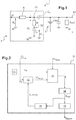
- an insulation fault detection system 1 between a terminal 21 of a high voltage circuit, here a high voltage battery 2 of a motor vehicle, and the mass M of this motor vehicle.
- This detection system 1 comprises a measuring circuit 3 and a detection device not shown on the figure 1 , for example a processor.
- the battery 2 is used to turn the front wheels and / or the rear wheels of an electric or hybrid vehicle.
- a regenerative braking can be implemented, that is to say that when the driver imposes a braking instruction, energy can be recovered and stored in the battery 2.
- the measuring circuit 3 comprises an input resistor R between an input terminal 30 and a connection terminal to the battery 31.
- the measuring circuit 3 further comprises, between the connection terminal 31 and the ground, a resistor R f and a capacitance C f .
- An output voltage U ' s is measured at a measurement point 32 between the resistor R f and the capacitance C f .
- the components R f and C f play here a role of low-pass filter.
- An input voltage U e is controlled by the processor and a measurement of the output voltage U ' s , or U ' Smes , is received by this processor.
- the measuring circuit 3 comprises a capacitive element C e between the battery 2 and the rest of the measuring circuit.
- Cisol capacity and the Risol resistance represent the equivalent capacity and the equivalent resistance, respectively, between the terminal 21 of the high voltage battery 2 and the ground.
- the input signal U e applied between the terminal 30 and the ground may be of the square step type with a frequency f e .
- This signal can be generated relatively easily by the processor, for example a microprocessor of a BMS module.
- the values of the low-pass filter elements R f and C f are known and relatively variable in time.
- the value of the input resistance R is also known.
- the value of the capacitive element C e is likely to vary, with variations of the order of 30% compared to the initial value, during the lifetime of the vehicle.
- the value of the insulation resistance Risol can vary especially in case of insulation fault. The value of this isolation resistance is thus likely to go from a few MOhms to only a few kOhms.
- the value of the isolation resistance is updated after a relatively long time. For example, for a frequency f e of the input signal U e of the order of 2 Hz, the acquisition frequency of the output signal U ' s being of the order of 100 Hz, if the method requires 100 points In order to be able to produce a correct value, it will take two periods, ie one second, to be able to update the value of the insulation resistance.
- the present invention can allow a faster update and in particular to each measurement, that is to say every 10 ms for example, and this, while ensuring a convergence of the estimate regardless of the capacitance C e .
- a discrete model of the measuring circuit is provided.
- a circuit z transform corresponding to a sampling period Te, for example 10 ms.
- Te a sampling period
- This model simulates the response of the measuring circuit.
- the figure 2 schematically represents an example of an insulation fault detection device 10 between the traction battery referenced 2 on the figure 1 and the mass.
- This device comprises a module 11 for generating an input signal U e .
- This signal is sent to the terminal 30 of the measuring circuit and is also received at the input of a digital modeling module of the measurement circuit 12.
- This module 12 estimates, using the equations above, and in particular the values common parameters k 1 , k 2 , k 3 , a theoretical value of the output signal U ' Smod .
- This value U ' Smod is received by a weighted difference estimation module 13.
- This module 13 further receives a measured value of output signal U' Smes, that is to say a voltage value measured at the terminal 32 of the measuring circuit 3 of the figure 1 .
- the module 13 calculates a difference between these two values U ' Smes and U' Smod .
- the sign of this difference is a function of the value of the input signal U e .
- the parameters k 1 , k 2 , k 3 are regularly updated so that the model of the measurement circuit is regularly updated.
- the model used by the module 12 varies according to the value of the estimated insulation resistance.
- This isolation resistance is estimated by looking for the values which tend to minimize the difference ⁇ between the response of the physical circuit U ' Smes and the U' Smod output of the model simulating the circuit.
- a regulator 14 makes it possible to estimate updated values of the isolation resistor R isol in order to converge the output of the model U ' Smod with the measurement U' Smes .
- the value of the estimated isolation resistance R isol is updated at each computation step.
- the module 14 tends to reduce the value of the estimated insulation resistance, that is to say that the model is slowed down.
- the module 14 tends to increase the value the estimated resistance R isol .
- the module 14 may be a proportional-integral type regulator with a difference ⁇ between the measured value U ' sms and the theoretical value U' Smod weighted by a sign depending on the value of the input signal U e .
- This weighting will be +1 when the input signal is 5 volts, ie in the case of a rising square, and will be -1 when the input signal is 0 volts, ie in the case of a descending niche.
- T e being the period of the input signal U e .
- the integral proportional regulator 14 can be adjusted according to the need and the compromise between speed and precision that one wishes to have on the estimate.
- the range of insulation resistance values can be very wide, from a few Ohms to a few MOhms, it is also possible to provide a variable gain as a function of the estimated insulation resistance value. If this value is relatively high, of the order of several hundred KOhms or MOhms, the need for precision is lower, but we will be interested in a quick solution. On the contrary, for a relatively low insulation resistance value, of the order of ten kOhms or less, it is necessary to have a better accuracy because this value represents a threshold of dangerousness.
- Variable K values can be defined according to external constraints such as the maximum detection time allowed to calculate and deliver the value of the insulation resistance.
- a module 15 makes it possible to update the values of the parameters k 1 , k 2 , k 3 by using the formula above in which the value of the capacitance C e can be chosen arbitrarily with an accuracy of plus or minus 50% in real terms.
- the initial value of this capacity can be used throughout the process, or at least for a number of cycles.
- a module 16 makes it possible to generate an alarm signal S alarm from the insulation resistance value from the model 14. This module 16 can for example compare the value of the insulation resistance with a threshold and trigger an alarm when the value of the insulation resistance is below this threshold.
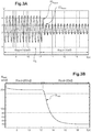
- the value of the insulation resistance calculated by the proportional integral regulator 14 drops very rapidly and converges towards the real value.
- the invention thus makes it possible to detect insulation faults in a simple and robust manner because of the tolerance to variations in the value of the capacitance C e .
Landscapes
- Physics & Mathematics (AREA)
- General Physics & Mathematics (AREA)
- Engineering & Computer Science (AREA)
- Computer Hardware Design (AREA)
- Microelectronics & Electronic Packaging (AREA)
- Chemical & Material Sciences (AREA)
- Combustion & Propulsion (AREA)
- Testing Of Short-Circuits, Discontinuities, Leakage, Or Incorrect Line Connections (AREA)
- Electric Propulsion And Braking For Vehicles (AREA)
- Measurement Of Resistance Or Impedance (AREA)
Applications Claiming Priority (2)
| Application Number | Priority Date | Filing Date | Title |
|---|---|---|---|
| FR1362092A FR3014206B1 (fr) | 2013-12-04 | 2013-12-04 | Estimation de la resistance d'isolement entre une batterie de vehicule automobile et la masse |
| PCT/FR2014/053115 WO2015082825A1 (fr) | 2013-12-04 | 2014-12-02 | Estimation de la resistance d'isolement entre une batterie de vehicule automobile et la masse |
Publications (2)
| Publication Number | Publication Date |
|---|---|
| EP3077834A1 EP3077834A1 (fr) | 2016-10-12 |
| EP3077834B1 true EP3077834B1 (fr) | 2018-04-11 |
Family
ID=50639615
Family Applications (1)
| Application Number | Title | Priority Date | Filing Date |
|---|---|---|---|
| EP14821774.8A Active EP3077834B1 (fr) | 2013-12-04 | 2014-12-02 | Estimation de la resistance d'isolement entre une batterie de vehicule automobile et la masse |
Country Status (6)
| Country | Link |
|---|---|
| US (1) | US10605845B2 (enExample) |
| EP (1) | EP3077834B1 (enExample) |
| JP (1) | JP2017501396A (enExample) |
| CN (1) | CN106415284B (enExample) |
| FR (1) | FR3014206B1 (enExample) |
| WO (1) | WO2015082825A1 (enExample) |
Families Citing this family (14)
| Publication number | Priority date | Publication date | Assignee | Title |
|---|---|---|---|---|
| US20180267089A1 (en) | 2016-12-19 | 2018-09-20 | Sendyne Corporation | Isolation monitoring device and method |
| KR102259382B1 (ko) | 2017-12-15 | 2021-06-01 | 주식회사 엘지에너지솔루션 | 배터리 누전을 검출하기 위한 방법 및 장치 |
| EP3546957A1 (en) * | 2018-03-28 | 2019-10-02 | Siemens Healthcare GmbH | Isolated grounding effectiveness monitor |
| FR3101425B1 (fr) * | 2019-09-30 | 2021-10-15 | Renault Sas | Procédé d’estimation de la résistance d’isolement d’un circuit haute tension d’un véhicule automobile électrique ou hybride |
| CN112230058B (zh) * | 2019-11-29 | 2023-06-16 | 蜂巢能源科技有限公司 | 电动汽车绝缘电阻的检测方法、装置及设备 |
| FR3109222B1 (fr) * | 2020-04-14 | 2023-06-16 | Renault Sas | Procédé de détection d’un défaut d’isolation électrique entre une source d’énergie électrique et une masse électrique |
| DE102020007243B3 (de) | 2020-11-27 | 2022-05-05 | Daimler Ag | Verfahren zum Bestimmen zumindest eines aktuellen Kapazitätswerts einer Y-Kapazität eines Hochvolt-Bordnetzes, sowie elektronische Recheneinrichtung |
| CN115078831B (zh) * | 2021-03-10 | 2025-11-11 | 北汽福田汽车股份有限公司 | 高压绝缘电阻检测方法与装置、存储介质、电池管理系统 |
| CN113310647B (zh) * | 2021-06-30 | 2022-11-15 | 中国第一汽车股份有限公司 | 电池包泄露检测的方法、装置、电子设备及存储介质 |
| CN116148536B (zh) * | 2023-03-28 | 2023-07-25 | 湖南大学 | 一种基于非平衡电桥法的电动汽车绝缘阻值检测方法 |
| FR3160017A1 (fr) | 2024-03-06 | 2025-09-12 | Stellantis Auto Sas | Procede de diagnostic d’un systeme electrique de puissance pour un vehicule electrifie |
| CN118731488B (zh) * | 2024-05-24 | 2025-12-05 | 中国第一汽车股份有限公司 | 汽车电池的绝缘电阻检测方法、计算模块、装置及汽车 |
| CN118624985B (zh) * | 2024-08-15 | 2024-11-05 | 湖南大学 | 电动汽车高压系统参数辨识方法及电子设备 |
| CN119749255B (zh) * | 2024-12-27 | 2025-11-11 | 湖南高速铁路职业技术学院 | 一种基于并联绝缘电阻检测的电动汽车绝缘故障定位方法 |
Family Cites Families (18)
| Publication number | Priority date | Publication date | Assignee | Title |
|---|---|---|---|---|
| FI74549C (fi) * | 1986-02-13 | 1988-02-08 | Vaisala Oy | Maetningsfoerfarande foer impedanser, saerskilt smao kapacitanser. |
| JPH026268U (enExample) * | 1988-06-28 | 1990-01-16 | ||
| TW418323B (en) * | 1998-02-19 | 2001-01-11 | Sumitomo Metal Ind | Capacitance detection system and method |
| JP2002323526A (ja) * | 2001-04-25 | 2002-11-08 | Japan Storage Battery Co Ltd | 絶縁抵抗劣化検出方法及びその装置 |
| JP3783633B2 (ja) * | 2002-02-26 | 2006-06-07 | 日産自動車株式会社 | 車両用地絡検出装置 |
| SE0401128D0 (sv) * | 2004-04-29 | 2004-04-29 | Subsee Ab | Mätinstrument |
| TW200624826A (en) * | 2004-10-29 | 2006-07-16 | Koninkl Philips Electronics Nv | System for diagnosing impedances having accurate current source and accurate voltage level-shift |
| US7548067B2 (en) * | 2006-10-25 | 2009-06-16 | Sematech, Inc. | Methods for measuring capacitance |
| JP4659067B2 (ja) * | 2008-05-26 | 2011-03-30 | 矢崎総業株式会社 | 絶縁計測方法及び絶縁計測装置 |
| JP4937293B2 (ja) * | 2009-03-31 | 2012-05-23 | 本田技研工業株式会社 | 地絡検知システムを備える電気自動車 |
| EP2256506B1 (de) * | 2009-05-27 | 2019-07-03 | Bender GmbH & Co. KG | Verfahren und Vorrichtung zur Isolationsüberwachung von ungeerdeten Gleich- und Wechselspannungsnetzen |
| DE102010006108A1 (de) * | 2010-01-29 | 2011-08-04 | Bayerische Motoren Werke Aktiengesellschaft, 80809 | Bestimmung einer Isolation in einem IT-System |
| US8618809B2 (en) * | 2010-06-15 | 2013-12-31 | Deere & Company | Electrical isolation detection with enhanced dynamic range |
| FR2963109B1 (fr) * | 2010-07-23 | 2012-08-17 | Saft Groupe Sa | Procede de determination d'un parametre d'au moins un accumulateur d'une batterie |
| KR101354583B1 (ko) * | 2010-09-17 | 2014-01-22 | 에스케이이노베이션 주식회사 | 누설전류를 발생시키지 않고 셀프 테스트 기능을 가진 절연저항 측정회로 |
| EP2575334A1 (en) * | 2011-09-30 | 2013-04-03 | British Telecommunications Public Limited Company | Line performance measure |
| US8878547B2 (en) * | 2011-10-31 | 2014-11-04 | Lear Corporation | Insulation resistance monitoring for vehicles with high-voltage power net |
| FR2987133B1 (fr) * | 2012-02-22 | 2014-02-07 | Renault Sas | Procede d'estimation de la resistance d'isolement entre une batterie et une masse electrique |
-
2013
- 2013-12-04 FR FR1362092A patent/FR3014206B1/fr not_active Expired - Fee Related
-
2014
- 2014-12-02 EP EP14821774.8A patent/EP3077834B1/fr active Active
- 2014-12-02 JP JP2016536133A patent/JP2017501396A/ja active Pending
- 2014-12-02 CN CN201480073856.XA patent/CN106415284B/zh not_active Expired - Fee Related
- 2014-12-02 US US15/101,741 patent/US10605845B2/en active Active
- 2014-12-02 WO PCT/FR2014/053115 patent/WO2015082825A1/fr not_active Ceased
Also Published As
| Publication number | Publication date |
|---|---|
| JP2017501396A (ja) | 2017-01-12 |
| EP3077834A1 (fr) | 2016-10-12 |
| WO2015082825A1 (fr) | 2015-06-11 |
| CN106415284A (zh) | 2017-02-15 |
| CN106415284B (zh) | 2019-04-02 |
| US10605845B2 (en) | 2020-03-31 |
| FR3014206A1 (fr) | 2015-06-05 |
| US20160334452A1 (en) | 2016-11-17 |
| FR3014206B1 (fr) | 2015-12-11 |
Similar Documents
| Publication | Publication Date | Title |
|---|---|---|
| EP3077834B1 (fr) | Estimation de la resistance d'isolement entre une batterie de vehicule automobile et la masse | |
| EP2888599B1 (fr) | Procédé d'estimation du vieillissement d'une batterie | |
| EP2847603B1 (fr) | Estimation de l'etat de charge d'une batterie | |
| EP3079940B1 (fr) | Evaluation de la quantite d'energie dans une batterie de vehicule automobile | |
| EP3047290B1 (fr) | Procede d'estimation du vieillissement d'une cellule de batterie d'accumulateurs | |
| FR2956486A1 (fr) | Methode de diagnostic in situ de batteries par spectroscopie d'impedance electrochimique | |
| EP3655788B1 (fr) | Procede de detection d'un defaut d'autodecharge dans une cellule de batterie | |
| FR2963109A1 (fr) | Procede de determination d'un parametre d'au moins un accumulateur d'une batterie | |
| EP2849964B1 (fr) | Système et procédé de charge sécurisée d'une batterie de véhicule automobile | |
| EP2850445B1 (fr) | Système et procédé correspondant d'estimation de l'état de charge d'une batterie | |
| EP4111219B1 (fr) | Procédé d'estimation de l'état de santé énergétique d'une batterie | |
| EP2959302A1 (fr) | Evaluation de l'energie extractible d'une batterie de vehicule automobile | |
| EP4352525B1 (fr) | Procede d'estimation de l'etat de sante resistif d'au moins un element de stockage d'energie electrique d'une batterie electrique | |
| EP3237919A1 (fr) | Procede d'estimation de grandeurs physiques caracteristiques d'une batterie electrique | |
| EP0859963B1 (fr) | Procede pour determiner l'etat de charge d'une batterie d'accumulateurs | |
| EP2406647A1 (fr) | Procede pour determiner l'etat de charge d'une source electrochimique pour la traction electrique de vehicules | |
| FR2958044A1 (fr) | Procede d'estimation de l'etat de charge et de l'etat de sante d'un systeme electrochimique | |
| WO2013060688A1 (fr) | Procede et systeme de determination d'etat de charge d'une cellule elementaire et d'une batterie | |
| EP3221710B1 (fr) | Procede de caracterisation d'un accumulateur | |
| EP3870984B1 (fr) | Procede d'estimation de la tension a circuit ouvert d'un accumulateur electrochimique de systeme de batterie | |
| EP4605767A1 (fr) | Vehicule automobile comprenant un systeme de determination d'impedance de batterie de traction, procede et programme sur la base d'un tel vehicule | |
| FR3045218A1 (fr) | Determination de parametres d'un modele dynamique pour une cellule electrochimique de batterie | |
| EP3480882B1 (fr) | Procédé et système de recharge pour une batterie d'accumulateurs d'un véhicule | |
| EP4639189A1 (fr) | Prédiction de l'état de santé d'un accumulateur d'énergie électrique | |
| FR2898985A1 (fr) | Procede et systeme de determination de l'etat de sante de moyens de stockage d'energie electrique. |
Legal Events
| Date | Code | Title | Description |
|---|---|---|---|
| PUAI | Public reference made under article 153(3) epc to a published international application that has entered the european phase |
Free format text: ORIGINAL CODE: 0009012 |
|
| 17P | Request for examination filed |
Effective date: 20160531 |
|
| AK | Designated contracting states |
Kind code of ref document: A1 Designated state(s): AL AT BE BG CH CY CZ DE DK EE ES FI FR GB GR HR HU IE IS IT LI LT LU LV MC MK MT NL NO PL PT RO RS SE SI SK SM TR |
|
| AX | Request for extension of the european patent |
Extension state: BA ME |
|
| DAX | Request for extension of the european patent (deleted) | ||
| REG | Reference to a national code |
Ref country code: DE Ref legal event code: R079 Ref document number: 602014023875 Country of ref document: DE Free format text: PREVIOUS MAIN CLASS: G01R0027020000 Ipc: G01R0031000000 |
|
| GRAP | Despatch of communication of intention to grant a patent |
Free format text: ORIGINAL CODE: EPIDOSNIGR1 |
|
| RIC1 | Information provided on ipc code assigned before grant |
Ipc: G01R 31/02 20060101ALI20170918BHEP Ipc: G01R 27/18 20060101ALI20170918BHEP Ipc: G01R 31/00 20060101AFI20170918BHEP |
|
| INTG | Intention to grant announced |
Effective date: 20171025 |
|
| GRAS | Grant fee paid |
Free format text: ORIGINAL CODE: EPIDOSNIGR3 |
|
| GRAA | (expected) grant |
Free format text: ORIGINAL CODE: 0009210 |
|
| AK | Designated contracting states |
Kind code of ref document: B1 Designated state(s): AL AT BE BG CH CY CZ DE DK EE ES FI FR GB GR HR HU IE IS IT LI LT LU LV MC MK MT NL NO PL PT RO RS SE SI SK SM TR |
|
| REG | Reference to a national code |
Ref country code: GB Ref legal event code: FG4D Free format text: NOT ENGLISH |
|
| REG | Reference to a national code |
Ref country code: CH Ref legal event code: EP |
|
| REG | Reference to a national code |
Ref country code: AT Ref legal event code: REF Ref document number: 988612 Country of ref document: AT Kind code of ref document: T Effective date: 20180415 |
|
| REG | Reference to a national code |
Ref country code: IE Ref legal event code: FG4D Free format text: LANGUAGE OF EP DOCUMENT: FRENCH |
|
| REG | Reference to a national code |
Ref country code: DE Ref legal event code: R096 Ref document number: 602014023875 Country of ref document: DE |
|
| REG | Reference to a national code |
Ref country code: NL Ref legal event code: MP Effective date: 20180411 |
|
| REG | Reference to a national code |
Ref country code: LT Ref legal event code: MG4D |
|
| PG25 | Lapsed in a contracting state [announced via postgrant information from national office to epo] |
Ref country code: NL Free format text: LAPSE BECAUSE OF FAILURE TO SUBMIT A TRANSLATION OF THE DESCRIPTION OR TO PAY THE FEE WITHIN THE PRESCRIBED TIME-LIMIT Effective date: 20180411 |
|
| PG25 | Lapsed in a contracting state [announced via postgrant information from national office to epo] |
Ref country code: ES Free format text: LAPSE BECAUSE OF FAILURE TO SUBMIT A TRANSLATION OF THE DESCRIPTION OR TO PAY THE FEE WITHIN THE PRESCRIBED TIME-LIMIT Effective date: 20180411 Ref country code: FI Free format text: LAPSE BECAUSE OF FAILURE TO SUBMIT A TRANSLATION OF THE DESCRIPTION OR TO PAY THE FEE WITHIN THE PRESCRIBED TIME-LIMIT Effective date: 20180411 Ref country code: AL Free format text: LAPSE BECAUSE OF FAILURE TO SUBMIT A TRANSLATION OF THE DESCRIPTION OR TO PAY THE FEE WITHIN THE PRESCRIBED TIME-LIMIT Effective date: 20180411 Ref country code: SE Free format text: LAPSE BECAUSE OF FAILURE TO SUBMIT A TRANSLATION OF THE DESCRIPTION OR TO PAY THE FEE WITHIN THE PRESCRIBED TIME-LIMIT Effective date: 20180411 Ref country code: NO Free format text: LAPSE BECAUSE OF FAILURE TO SUBMIT A TRANSLATION OF THE DESCRIPTION OR TO PAY THE FEE WITHIN THE PRESCRIBED TIME-LIMIT Effective date: 20180711 Ref country code: PL Free format text: LAPSE BECAUSE OF FAILURE TO SUBMIT A TRANSLATION OF THE DESCRIPTION OR TO PAY THE FEE WITHIN THE PRESCRIBED TIME-LIMIT Effective date: 20180411 Ref country code: LT Free format text: LAPSE BECAUSE OF FAILURE TO SUBMIT A TRANSLATION OF THE DESCRIPTION OR TO PAY THE FEE WITHIN THE PRESCRIBED TIME-LIMIT Effective date: 20180411 Ref country code: BG Free format text: LAPSE BECAUSE OF FAILURE TO SUBMIT A TRANSLATION OF THE DESCRIPTION OR TO PAY THE FEE WITHIN THE PRESCRIBED TIME-LIMIT Effective date: 20180711 |
|
| PG25 | Lapsed in a contracting state [announced via postgrant information from national office to epo] |
Ref country code: HR Free format text: LAPSE BECAUSE OF FAILURE TO SUBMIT A TRANSLATION OF THE DESCRIPTION OR TO PAY THE FEE WITHIN THE PRESCRIBED TIME-LIMIT Effective date: 20180411 Ref country code: RS Free format text: LAPSE BECAUSE OF FAILURE TO SUBMIT A TRANSLATION OF THE DESCRIPTION OR TO PAY THE FEE WITHIN THE PRESCRIBED TIME-LIMIT Effective date: 20180411 Ref country code: LV Free format text: LAPSE BECAUSE OF FAILURE TO SUBMIT A TRANSLATION OF THE DESCRIPTION OR TO PAY THE FEE WITHIN THE PRESCRIBED TIME-LIMIT Effective date: 20180411 Ref country code: GR Free format text: LAPSE BECAUSE OF FAILURE TO SUBMIT A TRANSLATION OF THE DESCRIPTION OR TO PAY THE FEE WITHIN THE PRESCRIBED TIME-LIMIT Effective date: 20180712 |
|
| REG | Reference to a national code |
Ref country code: AT Ref legal event code: MK05 Ref document number: 988612 Country of ref document: AT Kind code of ref document: T Effective date: 20180411 |
|
| PG25 | Lapsed in a contracting state [announced via postgrant information from national office to epo] |
Ref country code: PT Free format text: LAPSE BECAUSE OF FAILURE TO SUBMIT A TRANSLATION OF THE DESCRIPTION OR TO PAY THE FEE WITHIN THE PRESCRIBED TIME-LIMIT Effective date: 20180813 |
|
| REG | Reference to a national code |
Ref country code: DE Ref legal event code: R097 Ref document number: 602014023875 Country of ref document: DE |
|
| PG25 | Lapsed in a contracting state [announced via postgrant information from national office to epo] |
Ref country code: SK Free format text: LAPSE BECAUSE OF FAILURE TO SUBMIT A TRANSLATION OF THE DESCRIPTION OR TO PAY THE FEE WITHIN THE PRESCRIBED TIME-LIMIT Effective date: 20180411 Ref country code: CZ Free format text: LAPSE BECAUSE OF FAILURE TO SUBMIT A TRANSLATION OF THE DESCRIPTION OR TO PAY THE FEE WITHIN THE PRESCRIBED TIME-LIMIT Effective date: 20180411 Ref country code: RO Free format text: LAPSE BECAUSE OF FAILURE TO SUBMIT A TRANSLATION OF THE DESCRIPTION OR TO PAY THE FEE WITHIN THE PRESCRIBED TIME-LIMIT Effective date: 20180411 Ref country code: EE Free format text: LAPSE BECAUSE OF FAILURE TO SUBMIT A TRANSLATION OF THE DESCRIPTION OR TO PAY THE FEE WITHIN THE PRESCRIBED TIME-LIMIT Effective date: 20180411 Ref country code: DK Free format text: LAPSE BECAUSE OF FAILURE TO SUBMIT A TRANSLATION OF THE DESCRIPTION OR TO PAY THE FEE WITHIN THE PRESCRIBED TIME-LIMIT Effective date: 20180411 Ref country code: AT Free format text: LAPSE BECAUSE OF FAILURE TO SUBMIT A TRANSLATION OF THE DESCRIPTION OR TO PAY THE FEE WITHIN THE PRESCRIBED TIME-LIMIT Effective date: 20180411 |
|
| PLBE | No opposition filed within time limit |
Free format text: ORIGINAL CODE: 0009261 |
|
| STAA | Information on the status of an ep patent application or granted ep patent |
Free format text: STATUS: NO OPPOSITION FILED WITHIN TIME LIMIT |
|
| PG25 | Lapsed in a contracting state [announced via postgrant information from national office to epo] |
Ref country code: IT Free format text: LAPSE BECAUSE OF FAILURE TO SUBMIT A TRANSLATION OF THE DESCRIPTION OR TO PAY THE FEE WITHIN THE PRESCRIBED TIME-LIMIT Effective date: 20180411 Ref country code: SM Free format text: LAPSE BECAUSE OF FAILURE TO SUBMIT A TRANSLATION OF THE DESCRIPTION OR TO PAY THE FEE WITHIN THE PRESCRIBED TIME-LIMIT Effective date: 20180411 |
|
| 26N | No opposition filed |
Effective date: 20190114 |
|
| PG25 | Lapsed in a contracting state [announced via postgrant information from national office to epo] |
Ref country code: SI Free format text: LAPSE BECAUSE OF FAILURE TO SUBMIT A TRANSLATION OF THE DESCRIPTION OR TO PAY THE FEE WITHIN THE PRESCRIBED TIME-LIMIT Effective date: 20180411 |
|
| REG | Reference to a national code |
Ref country code: CH Ref legal event code: PL |
|
| PG25 | Lapsed in a contracting state [announced via postgrant information from national office to epo] |
Ref country code: LU Free format text: LAPSE BECAUSE OF NON-PAYMENT OF DUE FEES Effective date: 20181202 Ref country code: MC Free format text: LAPSE BECAUSE OF FAILURE TO SUBMIT A TRANSLATION OF THE DESCRIPTION OR TO PAY THE FEE WITHIN THE PRESCRIBED TIME-LIMIT Effective date: 20180411 |
|
| REG | Reference to a national code |
Ref country code: IE Ref legal event code: MM4A |
|
| REG | Reference to a national code |
Ref country code: BE Ref legal event code: MM Effective date: 20181231 |
|
| PG25 | Lapsed in a contracting state [announced via postgrant information from national office to epo] |
Ref country code: IE Free format text: LAPSE BECAUSE OF NON-PAYMENT OF DUE FEES Effective date: 20181202 |
|
| PG25 | Lapsed in a contracting state [announced via postgrant information from national office to epo] |
Ref country code: BE Free format text: LAPSE BECAUSE OF NON-PAYMENT OF DUE FEES Effective date: 20181231 |
|
| PG25 | Lapsed in a contracting state [announced via postgrant information from national office to epo] |
Ref country code: LI Free format text: LAPSE BECAUSE OF NON-PAYMENT OF DUE FEES Effective date: 20181231 Ref country code: CH Free format text: LAPSE BECAUSE OF NON-PAYMENT OF DUE FEES Effective date: 20181231 |
|
| PG25 | Lapsed in a contracting state [announced via postgrant information from national office to epo] |
Ref country code: MT Free format text: LAPSE BECAUSE OF FAILURE TO SUBMIT A TRANSLATION OF THE DESCRIPTION OR TO PAY THE FEE WITHIN THE PRESCRIBED TIME-LIMIT Effective date: 20180411 |
|
| PG25 | Lapsed in a contracting state [announced via postgrant information from national office to epo] |
Ref country code: TR Free format text: LAPSE BECAUSE OF FAILURE TO SUBMIT A TRANSLATION OF THE DESCRIPTION OR TO PAY THE FEE WITHIN THE PRESCRIBED TIME-LIMIT Effective date: 20180411 |
|
| PG25 | Lapsed in a contracting state [announced via postgrant information from national office to epo] |
Ref country code: CY Free format text: LAPSE BECAUSE OF FAILURE TO SUBMIT A TRANSLATION OF THE DESCRIPTION OR TO PAY THE FEE WITHIN THE PRESCRIBED TIME-LIMIT Effective date: 20180411 Ref country code: HU Free format text: LAPSE BECAUSE OF FAILURE TO SUBMIT A TRANSLATION OF THE DESCRIPTION OR TO PAY THE FEE WITHIN THE PRESCRIBED TIME-LIMIT; INVALID AB INITIO Effective date: 20141202 Ref country code: MK Free format text: LAPSE BECAUSE OF NON-PAYMENT OF DUE FEES Effective date: 20180411 |
|
| PG25 | Lapsed in a contracting state [announced via postgrant information from national office to epo] |
Ref country code: IS Free format text: LAPSE BECAUSE OF FAILURE TO SUBMIT A TRANSLATION OF THE DESCRIPTION OR TO PAY THE FEE WITHIN THE PRESCRIBED TIME-LIMIT Effective date: 20180811 |
|
| P01 | Opt-out of the competence of the unified patent court (upc) registered |
Effective date: 20230608 |
|
| PGFP | Annual fee paid to national office [announced via postgrant information from national office to epo] |
Ref country code: GB Payment date: 20231220 Year of fee payment: 10 |
|
| REG | Reference to a national code |
Ref country code: DE Ref legal event code: R081 Ref document number: 602014023875 Country of ref document: DE Owner name: AMPERE S.A.S., FR Free format text: FORMER OWNER: RENAULT S.A.S., BOULOGNE-BILLANCOURT, FR |
|
| PGFP | Annual fee paid to national office [announced via postgrant information from national office to epo] |
Ref country code: DE Payment date: 20241210 Year of fee payment: 11 |
|
| PGFP | Annual fee paid to national office [announced via postgrant information from national office to epo] |
Ref country code: FR Payment date: 20241224 Year of fee payment: 11 |
|
| REG | Reference to a national code |
Ref country code: GB Ref legal event code: 732E Free format text: REGISTERED BETWEEN 20250501 AND 20250507 |
|
| GBPC | Gb: european patent ceased through non-payment of renewal fee |
Effective date: 20241202 |
|
| PG25 | Lapsed in a contracting state [announced via postgrant information from national office to epo] |
Ref country code: GB Free format text: LAPSE BECAUSE OF NON-PAYMENT OF DUE FEES Effective date: 20241202 |