EP3077632B1 - Kombikraftwerksystem - Google Patents
Kombikraftwerksystem Download PDFInfo
- Publication number
- EP3077632B1 EP3077632B1 EP14805589.0A EP14805589A EP3077632B1 EP 3077632 B1 EP3077632 B1 EP 3077632B1 EP 14805589 A EP14805589 A EP 14805589A EP 3077632 B1 EP3077632 B1 EP 3077632B1
- Authority
- EP
- European Patent Office
- Prior art keywords
- steam
- super
- heater
- heaters
- line
- Prior art date
- Legal status (The legal status is an assumption and is not a legal conclusion. Google has not performed a legal analysis and makes no representation as to the accuracy of the status listed.)
- Active
Links
- XLYOFNOQVPJJNP-UHFFFAOYSA-N water Substances O XLYOFNOQVPJJNP-UHFFFAOYSA-N 0.000 claims description 107
- 238000011084 recovery Methods 0.000 claims description 58
- 238000000926 separation method Methods 0.000 claims description 39
- 238000001816 cooling Methods 0.000 claims description 21
- 238000000034 method Methods 0.000 claims description 18
- 238000011144 upstream manufacturing Methods 0.000 claims description 15
- 229920006395 saturated elastomer Polymers 0.000 claims description 9
- 238000007599 discharging Methods 0.000 claims description 3
- 238000010438 heat treatment Methods 0.000 claims description 3
- 239000007789 gas Substances 0.000 description 36
- 238000002347 injection Methods 0.000 description 7
- 239000007924 injection Substances 0.000 description 7
- 238000005352 clarification Methods 0.000 description 6
- 239000007921 spray Substances 0.000 description 6
- 230000003628 erosive effect Effects 0.000 description 5
- 238000010586 diagram Methods 0.000 description 4
- 230000000903 blocking effect Effects 0.000 description 2
- 239000003546 flue gas Substances 0.000 description 2
- 239000000243 solution Substances 0.000 description 2
- 230000008646 thermal stress Effects 0.000 description 2
- 230000001052 transient effect Effects 0.000 description 2
- UGFAIRIUMAVXCW-UHFFFAOYSA-N Carbon monoxide Chemical compound [O+]#[C-] UGFAIRIUMAVXCW-UHFFFAOYSA-N 0.000 description 1
- 238000010793 Steam injection (oil industry) Methods 0.000 description 1
- 230000001351 cycling effect Effects 0.000 description 1
- 230000009977 dual effect Effects 0.000 description 1
- 230000002265 prevention Effects 0.000 description 1
Images
Classifications
-
- F—MECHANICAL ENGINEERING; LIGHTING; HEATING; WEAPONS; BLASTING
- F01—MACHINES OR ENGINES IN GENERAL; ENGINE PLANTS IN GENERAL; STEAM ENGINES
- F01K—STEAM ENGINE PLANTS; STEAM ACCUMULATORS; ENGINE PLANTS NOT OTHERWISE PROVIDED FOR; ENGINES USING SPECIAL WORKING FLUIDS OR CYCLES
- F01K23/00—Plants characterised by more than one engine delivering power external to the plant, the engines being driven by different fluids
- F01K23/02—Plants characterised by more than one engine delivering power external to the plant, the engines being driven by different fluids the engine cycles being thermally coupled
- F01K23/06—Plants characterised by more than one engine delivering power external to the plant, the engines being driven by different fluids the engine cycles being thermally coupled combustion heat from one cycle heating the fluid in another cycle
- F01K23/10—Plants characterised by more than one engine delivering power external to the plant, the engines being driven by different fluids the engine cycles being thermally coupled combustion heat from one cycle heating the fluid in another cycle with exhaust fluid of one cycle heating the fluid in another cycle
- F01K23/101—Regulating means specially adapted therefor
-
- F—MECHANICAL ENGINEERING; LIGHTING; HEATING; WEAPONS; BLASTING
- F01—MACHINES OR ENGINES IN GENERAL; ENGINE PLANTS IN GENERAL; STEAM ENGINES
- F01K—STEAM ENGINE PLANTS; STEAM ACCUMULATORS; ENGINE PLANTS NOT OTHERWISE PROVIDED FOR; ENGINES USING SPECIAL WORKING FLUIDS OR CYCLES
- F01K13/00—General layout or general methods of operation of complete plants
- F01K13/02—Controlling, e.g. stopping or starting
-
- F—MECHANICAL ENGINEERING; LIGHTING; HEATING; WEAPONS; BLASTING
- F01—MACHINES OR ENGINES IN GENERAL; ENGINE PLANTS IN GENERAL; STEAM ENGINES
- F01K—STEAM ENGINE PLANTS; STEAM ACCUMULATORS; ENGINE PLANTS NOT OTHERWISE PROVIDED FOR; ENGINES USING SPECIAL WORKING FLUIDS OR CYCLES
- F01K23/00—Plants characterised by more than one engine delivering power external to the plant, the engines being driven by different fluids
- F01K23/02—Plants characterised by more than one engine delivering power external to the plant, the engines being driven by different fluids the engine cycles being thermally coupled
- F01K23/06—Plants characterised by more than one engine delivering power external to the plant, the engines being driven by different fluids the engine cycles being thermally coupled combustion heat from one cycle heating the fluid in another cycle
- F01K23/10—Plants characterised by more than one engine delivering power external to the plant, the engines being driven by different fluids the engine cycles being thermally coupled combustion heat from one cycle heating the fluid in another cycle with exhaust fluid of one cycle heating the fluid in another cycle
- F01K23/106—Plants characterised by more than one engine delivering power external to the plant, the engines being driven by different fluids the engine cycles being thermally coupled combustion heat from one cycle heating the fluid in another cycle with exhaust fluid of one cycle heating the fluid in another cycle with water evaporated or preheated at different pressures in exhaust boiler
-
- F—MECHANICAL ENGINEERING; LIGHTING; HEATING; WEAPONS; BLASTING
- F01—MACHINES OR ENGINES IN GENERAL; ENGINE PLANTS IN GENERAL; STEAM ENGINES
- F01K—STEAM ENGINE PLANTS; STEAM ACCUMULATORS; ENGINE PLANTS NOT OTHERWISE PROVIDED FOR; ENGINES USING SPECIAL WORKING FLUIDS OR CYCLES
- F01K3/00—Plants characterised by the use of steam or heat accumulators, or intermediate steam heaters, therein
- F01K3/14—Plants characterised by the use of steam or heat accumulators, or intermediate steam heaters, therein having both steam accumulator and heater, e.g. superheating accumulator
-
- F—MECHANICAL ENGINEERING; LIGHTING; HEATING; WEAPONS; BLASTING
- F02—COMBUSTION ENGINES; HOT-GAS OR COMBUSTION-PRODUCT ENGINE PLANTS
- F02C—GAS-TURBINE PLANTS; AIR INTAKES FOR JET-PROPULSION PLANTS; CONTROLLING FUEL SUPPLY IN AIR-BREATHING JET-PROPULSION PLANTS
- F02C6/00—Plural gas-turbine plants; Combinations of gas-turbine plants with other apparatus; Adaptations of gas-turbine plants for special use
- F02C6/18—Plural gas-turbine plants; Combinations of gas-turbine plants with other apparatus; Adaptations of gas-turbine plants for special use using the waste heat of gas-turbine plants outside the plants themselves, e.g. gas-turbine power heat plants
-
- F—MECHANICAL ENGINEERING; LIGHTING; HEATING; WEAPONS; BLASTING
- F22—STEAM GENERATION
- F22G—SUPERHEATING OF STEAM
- F22G5/00—Controlling superheat temperature
- F22G5/12—Controlling superheat temperature by attemperating the superheated steam, e.g. by injected water sprays
-
- F—MECHANICAL ENGINEERING; LIGHTING; HEATING; WEAPONS; BLASTING
- F05—INDEXING SCHEMES RELATING TO ENGINES OR PUMPS IN VARIOUS SUBCLASSES OF CLASSES F01-F04
- F05D—INDEXING SCHEME FOR ASPECTS RELATING TO NON-POSITIVE-DISPLACEMENT MACHINES OR ENGINES, GAS-TURBINES OR JET-PROPULSION PLANTS
- F05D2220/00—Application
- F05D2220/30—Application in turbines
- F05D2220/31—Application in turbines in steam turbines
-
- F—MECHANICAL ENGINEERING; LIGHTING; HEATING; WEAPONS; BLASTING
- F05—INDEXING SCHEMES RELATING TO ENGINES OR PUMPS IN VARIOUS SUBCLASSES OF CLASSES F01-F04
- F05D—INDEXING SCHEME FOR ASPECTS RELATING TO NON-POSITIVE-DISPLACEMENT MACHINES OR ENGINES, GAS-TURBINES OR JET-PROPULSION PLANTS
- F05D2220/00—Application
- F05D2220/30—Application in turbines
- F05D2220/32—Application in turbines in gas turbines
-
- Y—GENERAL TAGGING OF NEW TECHNOLOGICAL DEVELOPMENTS; GENERAL TAGGING OF CROSS-SECTIONAL TECHNOLOGIES SPANNING OVER SEVERAL SECTIONS OF THE IPC; TECHNICAL SUBJECTS COVERED BY FORMER USPC CROSS-REFERENCE ART COLLECTIONS [XRACs] AND DIGESTS
- Y02—TECHNOLOGIES OR APPLICATIONS FOR MITIGATION OR ADAPTATION AGAINST CLIMATE CHANGE
- Y02E—REDUCTION OF GREENHOUSE GAS [GHG] EMISSIONS, RELATED TO ENERGY GENERATION, TRANSMISSION OR DISTRIBUTION
- Y02E20/00—Combustion technologies with mitigation potential
- Y02E20/16—Combined cycle power plant [CCPP], or combined cycle gas turbine [CCGT]
Definitions
- the present invention relates to combined cycle system, in particular, to the steam temperature control in the heat recovery steam generator of the combined cycle system.
- a variant of such combined power plant concepts is the combined-cycle power plant, in which the gas turbine set and the water/steam cycle are coupled to one another on the water/steam side.
- the flue gas discharged by the gas turbine set is conducted through a heat recovery steam generator for the generation of steam and is then discharged into the surroundings.
- the steam generated in the heat recovery steam generator is fed, for example as live steam and/or re-heater steam, into the water/steam cycle at suitable points.
- the heat recovery steam generator may also be employed for condensate and/or feedwater preheating.
- a typical heat recovery steam generator includes an inlet for receiving the exhaust gases from the gas turbine and an outlet which exhausts the gases received from the gas turbine after heat energy has been extracted from the exhaust gases. Between the inlet and outlet is a flow path, in which multiple heat exchanger devices are located. The heat exchanger devices extract heat from the exhaust gas from the gas turbine as it travels from the inlet to the outlet.
- the heat exchanger devices within a heat recovery steam generator are organized in a particular pattern or order within the flow path between the inlet and the outlet.
- the heat exchanger devices include a low pressure evaporator, an intermediate pressure evaporator, and a high pressure evaporator.
- the heat recovery steam generator may also include one or more economizers which preheat water before the water is delivered into one of the evaporators.
- the heat recovery steam generator can include one or more super-heaters which further heat steam produced by one of the evaporators.
- additional heat exchange elements such as re-heaters, can also be included at various locations along the flow path for various purposes.
- Steam temperature must be controlled according to steam turbine requirement(set values) for transient operations such as start-up, shut down and plant loading and de-loading.
- set values for transient operations such as start-up, shut down and plant loading and de-loading.
- introduction additional de-super-heater upstream final super-heater became mandatory. This had impact on plant cost, still leaving problems with exit-stage de-super-heater unsolved: minimum flow requirement, erosion of the valve and controllability.
- Exit-stage de-super-heater must operate always with minimum flow to ensure small temperature difference across the valve. In some operation regimes, such as Base Load(BL) at low ambient temperature and Low Load operation(LLO), no de-superheating flow is required due to low gas turbine exhaust temperature. Minimum flow causes unnecessary temperature reduction which causes performance reduction(Base Load) or thermal stress on steam turbine(Low Load operation). For exit-stage de-super-heater, water is extracted from high pressure economizer, which cause high pressure upstream of de-super-heater valve, especially during start up, shut down and LLO. This causes erosion of the valve. During plant transient(e.g. start up), the minimum flow causes an unnecessary reduction of the temperature reduction.
- Base Load(BL) at low ambient temperature and Low Load operation(LLO) no de-superheating flow is required due to low gas turbine exhaust temperature.
- Minimum flow causes unnecessary temperature reduction which causes performance reduction(Base Load) or thermal stress on steam turbine(Low Lo
- Exit-stage de-super-heater controls the temperature at HRSG outlet, leaving out the temperature control of components with thick wall such as final super heater inlet/outlet heater and manifolds.
- the problem with minimum flow amount and erosion of the valves is solved with dual spray de-super-heater valve.
- One for large flow demand and the other for small flow demand. This solution increases the cost and the minimum flow remains still too high regarding the impact on the steam temperature. In most cases, erosion on small valve has been detected.
- a cascaded de-super-heater station, one upstream final super-heater and the other downstream final super-heater solves life time problems of components with thick walls, but increases the plant costs.
- a heat recovery steam generator uses heat energy extracted from the exhaust gas of a gas turbine to produce steam is disclosed in EP2584157A1 .
- the steam is provided to steam turbines of a combined cycle power plant.
- Intermediate pressure steam generated by an intermediate pressure evaporator is routed to first and second intermediate pressure super-heaters.
- steam exhausted from a high pressure steam turbine of a combined cycle power plant is reheated by first and second re-heaters within the heat recovery steam generator.
- the steam output by the intermediate pressure super-heaters is provided to an inter-stage admission port of an intermediate pressure steam turbine, and steam output by the first and second re-heaters is provided as the main input steam for the intermediate pressure steam turbine of the combined cycle power plant.
- EP 0736669 A2 (see also US 5628179 ), which includes a gas turbine, a steam turbine and a heat recovery steam generator (HRSG), wherein gas turbine exhaust gas is used in the heat recovery steam generator for heating steam for the steam turbine, the gas turbine exhaust gas flowing from an entry end to an exit end of the HRSG, and wherein the HRSG includes at least one high pressure evaporator arranged to supply steam to a super-heater including multiple passes including a first pass at one end thereof adjacent the evaporator, and a final pass adjacent an opposite end thereof and adjacent the entry end of the heat recovery steam generator, and one or more intermediate passes between the first and final passes, the improvement comprising an attemperating conduit not exposed to the gas turbine exhaust gas, connecting the one end and the opposite end of the super-heater, bypassing the intermediate passes to thereby introduce cooler superheated steam from the one end into the super-heater at the opposite end.
- HRSG heat recovery steam generator
- a combined cycle power plant is disclosed in US6263662B1 as well as in US6578352B2 , which includes a gas turbine plant, a heat recovery steam generator, and a steam turbine plant.
- the heat recovery steam generator includes a main stream side steam piping, a bypass side steam piping, a steam branching to branch a steam flowing from a former stage in the heat recovery steam generator into two steams, one as a main stream side steam and another as a de-superheating steam, and a steam merging portion to merge the main stream side steam superheated by the high pressure super-heater and the de-superheating steam passed through the bypass side steam piping.
- the heat recovery steam generator is provided with a blocking prevention function to prevent blocking of the main stream side steam piping and the bypass side steam piping and a thermal stress generation protection function.
- It is an object of the present invention is to provide a steam temperature control arrangement for combined cycle system which may at least alleviate the problems as mentioned above.
- the set of super-heaters comprise a first super-heater, a second super-heater and a third super-heater which is arranged along the flow path, with the first super-heater being arranged upstream of the second and third super-heater
- the system further comprises a high pressure cooling line connected between an exit end of the high pressure economizer and an entry end of the first super-heater, with a high pressure inter-stage de-super-heater disposed therein to introduce a portion of water that is discharged from the high pressure economizer into the steam that is input into the first super-heater.
- the set of super-heaters comprise a first super-heater, a second super-heater and a third super-heater which are arranged along the flow path, with the first super-heater being arranged upstream of the second and third super-heaters
- the system further comprises a high pressure cooling line connected between an exit end of the water separation unit and an entry end of the first super-heater, to introduce a portion of water that is discharged from the water separation unit into tne steam that is input into the first super-heater, and an inter-stage control valve is disposed in the high pressure cooling line.
- the system further comprises a intermediate pressure economizer, a second water separation unit (e.g. an intermediate pressure drum), and a set of re-heaters, and the steam discharged from the second water separation unit is mixed with steam expanded through high pressure part of steam turbine and then routed through an intermediate pressure outlet line to the set of re-heaters and discharged from the set of re-heaters through a secondary outlet line of the heat recovery steam generator to be introduced into the steam turbine, the system further comprises a secondary attemperating line connected between the intermediate pressure outlet line and the secondary outlet line of the heat recovery steam generator to introduce a portion of steam that is discharged from the second water separation unit and high pressure part of steam turbine into the steam discharged from the set of re-heaters, and that a secondary control valve is disposed in the secondary attemperating line.
- a secondary attemperating line connected between the intermediate pressure outlet line and the secondary outlet line of the heat recovery steam generator to introduce a portion of steam that is discharged from the second water separation unit and high pressure
- the set of re-heaters comprise a first re-heater and a second re-heater disposed downstream of the first re-heater in the flow path
- the system further comprises an intermediate pressure cooling line connected between an exit end of the intermediate pressure economizer and an entry end of the first re-heater, with an intermediate pressure inter-stage de-super-heater disposed therein to introduce a portion of water that is discharged from the intermediate pressure economizer into the steam that is input into the first re-heater.
- the attemperating line is connected to the main outlet line of the heat recovery steam generator directly after the water separation unit.
- tne water separation unit is a water separator or a high pressure drum.
- Another embodiment of the invention provides a method of operating a combined cycle system according to claim 7.
- the set of super-heaters comprise first, second and third super-heaters arranged along the flow path of the hot flue gases, the first super-heater being arranged upstream of the second and third super-heater, the method additionally comprising the step of introducing a portion of the water discharged from the high pressure economizer into a high pressure cooling line connected between an exit end of the high pressure economizer and an entry end of the first super-heater.
- the temperature of the superheated steam admitted to the steam turbine can be controlled by controlling the mass flow of saturated steam admixed through the attemperating line.
- tne set ot super-heaters comprise a first super-heater, a second super-heater and a third super-heater which are arranged along the flow path, with the first super-heater being arranged the upstream of the second and third super-heaters
- the system further comprises a high pressure cooling line connected between an exit end of the water separation unit and an entry end of the first super-heater, the method additionally comprising introducing a portion of steam that is discharged from the water separation unit into the steam that is input into the first super-heater.
- the system further comprises an intermediate pressure economizer, a second water separation unit (e.g. an intermediate pressure drum), and a set of re-heaters, the method additionally comprising mixing steam discharged from the second water separation unit with steam from the high pressure steam turbine, the steam from the high pressure steam turbine being routed through an intermediate pressure outlet line to the set of re-heaters and discharged from the set of re-heaters through a secondary outlet line of the heat recovery steam generator to be introduced into the intermediate steam turbine, and wherein the system further comprises a secondary attemperating line connected between the intermediate pressure outlet line and the secondary outlet line of the heat recovery steam generator, the method additionally comprising introducing a portion of steam that is discharged from the intermediate pressure outlet line into the steam discharged from the set of re-heaters.
- the temperature of the re-heated steam for admission to the medium pressure steam turbine can be controlled.
- the set of re-heaters comprises a first re-heater and a second re-heater disposed downstream of the first re-heater in the flow path
- the system further comprises an intermediate pressure cooling line connected between an exit end of the intermediate pressure economizer and an entry end of the first re-heater, with an intermediate pressure inter-stage de-super-heater disposed therein
- the method further comprises introducing a portion of water that is discharged from the intermediate pressure economizer into the steam that is input into the first re-heater.
- the water separation unit is a water separator or a high pressure drum.
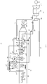
- FIG 1 shows a schematic diagram of a combined cycle system 10, which comprises a gas turbine 102, a steam turbine 106 and heat recovery steam generator 20.
- the gas turbine 102 is connected with a generator 104
- the steam turbine 106 is connected with a generator 113.
- the steam turbine 106 consists of a high pressure steam turbine 108, an intermediate pressure steam turbine 110 and a low pressure steam turbine 112.
- High temperature exhaust gas produced by the gas turbine 102 is guided to the heat recovery steam generator 20.
- the heat recovery steam generator 20 adopts, as an example, a 3-pressure system of high, intermediate and low pressure.
- a water separation unit in this case a high pressure drum 126), an intermediate pressure drum 130 and a low pressure drum (not shown) are installed for one of the three pressure portion, respectively.
- another water separation unit such as a water separator could also be provided. Further details on water separation units are provided below.
- a high pressure economizer 132, a high pressure evaporator 124, and a set of super-heaters including a first super-heater 114, a second super-heater 116 and a third super-heater 118 are connected with the high pressure drum 126 by steam lines, which will be explained in detail below.
- An Intermediate economizer 134, an intermediate evaporator 128, and a set of re-heaters including a first re-heater 120 and a second re-heater 122 are connected with the intermediate pressure drum 130 by steam lines, which will be explained in detail below.
- the end proximate to the gas turbine 102 is referred to be the upstream end or entry end, and the end distal to the gas turbine 102 is referred to be the downstream end or exit end.
- the exhaust gas discharged from the gas turbine passes the heat recovery steam generator 20 along a flow path defined between the upstream/entry end and downstream/exit end.
- the first super-heater 114 is disposed at the upstream end of the heat recovery steam generator 20.
- the steam in the first super-heater 114 is heated to the highest temperature by the exhaust gas.
- the first super-heater 114 is referred to be the exit-stage.
- the second super-heater 116 and the third super-heater 118 are disposed downstream of the first super-heater 114 along the flow path.
- the first re-heater 120 is disposed upstream of the second re-heater 122 in the flow path.
- additional economizer, re-heater may be connected with the low pressure drum.
- additional super-heaters and re-heaters and other heat exchange devices may be provided in the flow path for other functions facilitating operation of the heat recovery steam generator 20.
- the operation of the heat recovery steam generator 20 is explained in detail below.
- the water preheated in the high pressure economizer 132 is passed to the high pressure drum 126 through water line 204, where the saturated steam generated by the high pressure evaporator 124 is discharge through steam line 216 into the set of super-heaters, in particular, into the third super-heater 118.
- Steam line 216 may be defined as the high pressure outlet line for sake of clarification.
- the steam superheated by the third, second and first super-heater 118, 116 and 114 is discharged through steam line 226 into the high pressure steam turbine 108, where the steam is expanded to drive the generator 113.
- the steam line 226 may be defined as the main outlet line of the heat recovery steam generator 20 for sake of clarification.
- relatively cold steam is introduced into the steam line 226.
- a portion of the steam from the high pressure drum 126 is introduced into the final stage of the heat recovery steam generator 20.
- the steam line 216 discharging steam from the high pressure drum 126 is branched to be two steam lines 228 and 230, where steam line 228 is used to pass steam into the set of super-heaters, and the steam line 230 is used to introduce a portion of steam that is discharged from the high pressure drum 126 into the steam discharged from the set of super-heaters 118, 116 and 114.
- an attemperating line(steam line 230) is connected between the high pressure outlet line and the main outlet line of the heat recovery steam generator 20 that is discharged from the high pressure drum 126 into the steam discharged from the set of super-heaters.
- a control valve 144 is disposed in the steam line 230 to adjust the amount of steam that is introduced into the steam line 226 in order to adjust the steam temperature to be input into the high pressure steam turbine 108. As shown in Fig.1 , the steam line 230 and the steam line 226 is merged into the steam line 232 which is directed to the high pressure steam turbine 108.
- This arrangement according to the embodiment of the present invention may be referred to be exit-stage steam spray injection, which may substantially reduce the pressure difference across the control valve 144 compared with traditional water injection.
- a portion of water discharged from the high pressure economizer is introduced into the steam that enters the first super-heater through a de-super-heater in order to further control the steam temperature in the steam cycle.
- the water line 204 that exits the high pressure economizer 132 is branched to be two water lines 210 and 212, where the water line 212 is used to pass the water into the high pressure drum 126, the water line 210 is used to introduce a portion of water discharged from the high pressure economizer 132 into the steam line 222 that exits from the second super-heater.
- the water line 210 may be defined as the high pressure cooling line for sake of clarification.
- a high pressure cooling line is connected between an exit end of the high pressure economizer 132 and an entry end of the first super-heater 114.
- a high pressure inter-stage de-super-heater 142 is disposed in the steam line 222 in order to cool down the steam in the steam line 222, and a control valve 140 is disposed in the water line 210 to adjust the amount of water entering into the steam line 222. As shown in Fig. 1 , the water line 210 and the steam line 222 is merged into the steam line 224 which is directed to the first super-heater 114. This arrangement can allow sufficient steam flow through all super-heaters.
- the water preheated in the intermediate pressure economizer 134 is passed to the intermediate pressure drum 130 through water line 202, where the saturated steam generated by the intermediate pressure evaporator 128 is discharge through steam line 214 and after mixing with the expanded steam from steam turbine 108 is discharged through steam line 215 into the set of re-heaters, in particular, into the second re-heater 122.
- the steam line 215 may be defined as the intermediate pressure outlet line for sake of clarification.
- the steam superheated by the second and first re-heater 122 and 120 is discharged through steam line 236 into the intermediate pressure steam turbine 110, where the steam is expanded to drive the generator 113.
- the steam line 236 may be defined as the secondary outlet line of the heat recovery steam generator 20 for sake of clarification.
- relatively cold steam is introduced into the steam line 236.
- a portion of the steam from the intermediate pressure drum 130 and expanded steam from steam turbine 108 is introduced into the exit-stage of the heat recovery steam generator 20.
- the steam line 214 that exits the intermediate pressure drum 130 is joined with the steam line 240 exits the steam turbine 108 into steam line 215.
- Steam line 215 is branched to be two steam lines 218 and 220, where the steam line 220 is used to introduce the steam into the set of re-heaters 122 and 120, and the steam line 218 is used to bypass a portion of steam discharged from the intermediate pressure drum 130 and steam tubine 108 into the steam discharged from the first re-heater 120.
- a secondary attemperating line(steam line 218) is connected between the intermediate pressure outlet line and the secondary outlet line of the heat recovery steam generator 20 to introduce a portion of steam that is discharged from the intermediate pressure outlet line 215 into the steam discharged from the set of re-heaters120,122.
- a control valve 146 is disposed in the steam line 218 to adjust the amount of steam input into the steam line 236 so that the temperature of steam in steam line 238 input into the intermediate pressure steam turbine 110 is controlled according to operation requirement.
- a portion of water discharged from the intermediate pressure economizer 134 is introduced into the steam that enters the first re-heater through a de-super-heater 136 in order to further control the steam temperature in the steam cycle.
- the water line 202 exits the intermediate pressure economizer 134 is branched to be two water lines 206 and 208, where the water line 208 is used to pass the water into the intermediate pressure drum 130, the water line 206 is used to introduce a portion of water discharged from the intermediate pressure economizer 134 into the steam line 234 that exits from the second re-heater 122.
- the water line 206 may be defined as the intermediate pressure cooling line tor sake of clarification.
- an intermediate pressure cooling line is connected between an exit end of the intermediate pressure economizer 134 and an entry end of the first re-heater 120.
- a intermediate pressure inter-stage de-super-heater 136 is disposed in the water line 206 in order to produce water to cool down the steam in the steam line 234, and a control valve 138 is disposed in the water line 206 to adjust the amount of water entering into the steam line 234 so that the temperature of steam in steam line 234 input into the first re-heater 120 is controlled according to operation requirement.
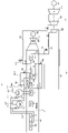
- Fig.2 shows a schematic diagram of another embodiment of the combined cycle system according to the present invention. Most of the arrangement as shown in Fig.2 is the same with that of Fig.1 except the inter-stage cooling arrangement as detailed explained below.
- a portion of steam discharged from the high pressure drum 126 is introduced into the steam that enters the first super-heater 114.
- the steam line 228 enters the third super-heater 118 is branched into two steam lines 229 and 2101, where the steam line 229 is used to pass the steam into the third super-heater 118, and the steam line 2101 is used to pass a portion of steam discharged from the high pressure drum 126 into the first super-heater 114 through the control valve 140.
- the high pressure inter-stage de-super-heater is dispensed.
- the steam line 2101 may be defined also as the high pressure cooling line.
- a high pressure cooling line 2101 is connected between an exit end of the high pressure drum 126 and an entry end of the first super-heater 114, to introduce a portion of steam that is discharged from the high pressure drum 126 into the steam that is input into the first super-heater 114.
- the steam line 215 is branched into two steam lines 220 and 2061, where the steam line 220 is used to pass steam into the second re-heater 122, and the steam line 2061 is used to pass a portion of steam that is discharged through steam line 215 into the first re-heater 120 through the control valve 138.
- the intermediate pressure inter-stage de-super-heater is dispensed.
- any of the pressure drums may be replaced by another water separation unit such as a water separator.
- a water separator is a mechanical object for collecting water droplets dispersed in a steam flow. It can for example be a separation bottle or steam bottle. Water separation units avoid damage to the turbine that could otherwise be caused by water droplets. In this way, the coldest available steam can be used (e.g. from a heat recovery steam generator with a drum as shown in the Figures, or after a water separator in a once-through heat recovery steam generator) .
Landscapes
- Engineering & Computer Science (AREA)
- Chemical & Material Sciences (AREA)
- Combustion & Propulsion (AREA)
- Mechanical Engineering (AREA)
- General Engineering & Computer Science (AREA)
- Engine Equipment That Uses Special Cycles (AREA)
- Control Of Turbines (AREA)
Claims (12)
- Kombiniertes Kreislaufsystem (10), das eine Gasturbine (102), eine Dampfturbine (106) und einen Wärmerückgewinnungsdampfgenerator (20) umfasst, wobei das Gasturbinenabgas von einem Eintrittsende des Wärmerückgewinnungsdampfgenerators zu einem Austrittsende des Wärmerückgewinnungsdampfgenerators strömt, um einen Strömungsweg zum darin Erwärmen von Dampf für die Dampfturbine zu bilden, und wobei der Wärmerückgewinnungsdampfgenerator einen Hochdruck-Economizer (132), eine Wasserabscheideeinheit (126) und einen Satz Überhitzer (114, 116, 118) umfasst, wobei der aus der Wasserabscheideeinheit abgegebene Dampf durch eine Hochdruckauslassleitung (216) an den Satz Überhitzer geleitet und aus dem Satz Überhitzer durch eine Hauptauslassleitung (226) des Wärmerückgewinnungsdampfgenerators abgegeben wird, um in die Dampfturbine eingeführt zu werden, wobeieine Vortemperierungsleitung (230) zwischen der Hochdruckauslassleitung (216) und der Hauptauslassleitung (226) des Wärmerückgewinnungsdampfgenerators verbunden ist, um einen Anteil gesättigten Dampf, der aus der Wasserabscheideeinheit abgegeben wird, in den Dampf einzuführen, der aus dem Satz Überhitzer abgegeben wird, und ein Steuerventil (144) in der Vortemperierungsleitung angeordnet ist; dadurch gekennzeichnet, dassdie Vortemperierungsleitung (230) mit der Hauptauslassleitung (226) des Wärmerückgewinnungsdampfgenerators direkt nach der Wasserabscheideeinheit (126) verbunden ist.
- Kombiniertes System nach Anspruch 1, wobei der Satz Überhitzer einen ersten Überhitzer (114), einen zweiten Überhitzer (116) und einen dritten Überhitzer (118) umfasst, die entlang des Strömungswegs angeordnet sind, wobei der erste Überhitzer stromaufwärts des zweiten und dritten Überhitzers angeordnet ist, wobei das System ferner eine Hochdruckkühlleitung umfasst, die zwischen einem Austrittsende des Hochdruck-Economizers und einem Eintrittsende des ersten Überhitzers verbunden ist, wobei ein Hochdruckzwischenkühler darin angeordnet ist, um einen Anteil Wasser, das aus dem Hochdruck-Economizer abgegeben wird, in den Dampf einzuführen, der in den ersten Überhitzer eingeleitet wird.
- Kombiniertes System nach Anspruch 1, wobei der Satz Überhitzer einen ersten Überhitzer, einen zweiten Überhitzer und einen dritten Überhitzer umfasst, die entlang des Strömungswegs angeordnet sind, wobei der erste Überhitzer stromaufwärts des zweiten und dritten Überhitzers angeordnet ist, wobei das System ferner eine Hochdruckkühlleitung (2101) umfasst, die zwischen einem Austrittsende der Wasserabscheideeinheit und einem Eintrittsende des ersten Überhitzers verbunden ist, um einen Anteil Dampf, der aus der Wasserabscheideeinheit abgegeben wird, in den Dampf einzuführen, der in den ersten Überhitzer eingeleitet wird, und ein Zwischensteuerventil in der Hochdruckkühlleitung angeordnet ist.
- Kombiniertes System nach und der Ansprüche 1 bis 3, wobei das System ferner einen Zwischendruck-Economizer (134), eine zweite Wasserabscheideeinheit und einen Satz Nacherhitzer (120, 122) umfasst und der aus der zweiten Wasserabscheideeinheit abgegebene Dampf mit dem Dampf aus der Hochdruckdampfturbine gemischt, durch eine Zwischendruckauslassleitung zu dem Satz Nacherhitzer geleitet und aus dem Satz Nacherhitzer durch eine sekundäre Auslassleitung des Wärmerückgewinnungsdampfgenerators abgegeben wird, um in die Zwischendampfturbine eingeführt zu werden, wobei das System ferner eine sekundäre Vortemperierungsleitung (218) umfasst, die zwischen der Zwischendruckauslassleitung und der sekundären Auslassleitung des Wärmerückgewinnungsdampfgenerators verbunden ist, um einen Anteil Dampf, der aus der Zwischendruckauslassleitung abgegeben wird, in den Dampf einzuführen, der aus dem Satz Nacherhitzer abgegeben wird, und ein sekundäres Steuerventil (146) in der sekundären Vortemperierungsleitung angeordnet ist.
- Kombiniertes System nach und der Ansprüche 1 bis 4, wobei der Satz Nacherhitzer einen ersten Nacherhitzer (120) und einen zweiten Nacherhitzer (122), der stromabwärts des ersten Nacherhitzers in dem Strömungsweg angeordnet ist, umfasst, wobei das System ferner eine Zwischendruckkühlleitung (206) umfasst, die zwischen einem Austrittsende des Zwischendruck-Economizers und einem Eintrittsende des ersten Nacherhitzers verbunden ist, wobei ein Zwischendruckzwischenkühler (136) darin angeordnet ist, um einen Anteil Wasser, das aus dem Zwischendruck-Economizer abgegeben wird, in den Dampf einzuführen, der in den ersten Nacherhitzer eingeleitet wird.
- Kombiniertes System nach einem der vorstehenden Ansprüche, wobei die Wasserabscheideeinheit ein Wasserabscheider oder eine Hochdrucktrommel (126) ist.
- Verfahren zum Betreiben eines kombinierten Kreislaufsystems (10), das eine Gasturbine (102), eine Dampfturbine (106) und einen Wärmerückgewinnungsdampfgenerator (20) umfasst, der einen Hochdruck-Economizer (132), eine Wasserabscheideeinheit (126) und einen Satz Überhitzer (114, 116, 118) umfasst, wobei das Gasturbinenabgas von einem Eintrittsende des Wärmerückgewinnungsdampfgenerators zu einem Austrittsende des Wärmerückgewinnungsdampfgenerators strömt, um einen Strömungsweg zum darin Erwärmen von Dampf für die Dampfturbine zu bilden, wobei das Verfahren die Schritte umfasst- Vorheizen von Wasser in dem Hochdruck-Economizer und Leiten des Wassers zu der Wasserabscheideeinheit,- Erzeugen von gesättigtem Dampf in einem Hochdruckverdampfer (124) und Leiten des gesättigten Dampfs zu der Wasserabscheideeinheit,- Entladen eines Teils des gesättigten Dampfs aus der Wasserabscheideeinheit in den Satz Überhitzer,- Überhitzen des gesättigten Dampfs in dem Satz Überhitzer, um überhitztem Dampf zu erzeugen, und- Abgeben des überhitzten Dampfs in die Dampfturbine,- wobei
ein Anteil des gesättigten Dampfs, der aus der Wasserabscheideeinheit abgegeben wird, durch eine Vortemperierungsleitung (230) aus der Wasserabscheideeinheit in den überhitzten Dampf abgegeben wird, der aus dem Satz Überhitzer abgegeben wird; dadurch gekennzeichnet, dass- die Vortemperierungsleitung (230) mit einer Hauptauslassleitung des Wärmerückgewinnungsdampfgenerators direkt nach der Wasserabscheideeinheit verbunden ist. - Verfahren nach Anspruch 7, wobei der Satz Überhitzer einen ersten, zweiten und dritten Überhitzer (114, 116, 118) umfasst, die entlang des Strömungswegs angeordnet sind, wobei der erste Überhitzer stromaufwärts des zweiten und dritten Überhitzers angeordnet ist,
wobei das Verfahren zusätzlich den Schritt des Einführens eines Anteils des Wassers, das aus dem Hochdruck-Economizer abgeleitet wird, in eine Hochdruckkühlleitung, die zwischen einem Austrittsende des Hochdruck-Economizers und einem Eintrittsende des ersten Überhitzers verbunden ist, umfasst. - Verfahren nach Anspruch 7, wobei der Satz Überhitzer einen ersten Überhitzer (114), einen zweiten Überhitzer (116) und einen dritten Überhitzer (118) umfasst, die entlang des Strömungswegs angeordnet sind, wobei der erste Überhitzer stromaufwärts des zweiten und dritten Überhitzers angeordnet ist, wobei das System ferner eine Hochdruckkühlleitung umfasst, die zwischen einem Austrittsende der Wasserabscheideeinheit und einem Eintrittsende des ersten Überhitzers verbunden ist,
wobei das Verfahren zusätzlich das Einführen eines Anteils Dampf, der aus der Wasserabscheideeinheit abgegeben wird, in den Dampf, der in den ersten Überhitzer eingeleitet wird, umfasst. - Verfahren nach einem der Ansprüche 7 bis 9, wobei das System ferner einen Zwischendruck-Economizer (134), eine zweite Wasserabscheideeinheit und einen Satz Nacherhitzer (120, 122) umfasst,wobei das Verfahren zusätzlich das Mischen von Dampf, der aus der zweiten Wasserabscheideeinheit abgegeben wird, mit Dampf aus der Hochdruckdampfturbine umfasst, wobei der Dampf aus der Hochdruckdampfturbine durch eine Zwischendruckauslassleitung zu dem Satz Nacherhitzer geleitet und aus dem Satz Nacherhitzer durch eine sekundäre Auslassleitung des Wärmerückgewinnungsdampfgenerators abgegeben wird, um in die Zwischendampfturbine eingeführt zu werden,und wobei das System ferner eine sekundäre Vortemperierungsleitung (218) umfasst, die zwischen der Zwischendruckauslassleitung und der sekundären Auslassleitung des Wärmerückgewinnungsdampfgenerators verbunden ist,wobei das Verfahren zusätzlich das Einführen eines Anteils Dampf, der aus der Zwischendruckauslassleitung abgegeben wird, in den Dampf, der aus dem Satz Überhitzer abgegeben wird, umfasst.
- Verfahren nach einem der Ansprüche 7 bis 10, wobei der Satz Nacherhitzer einen ersten Nacherhitzer (120) und einen zweiten Nacherhitzer (122), der stromabwärts des ersten Nacherhitzers in dem Strömungsweg angeordnet ist, umfasst, wobei das System ferner eine Zwischendruckkühlleitung (206) umfasst, die zwischen einem Austrittsende des Zwischendruck-Economizers und einem Eintrittsende des ersten Nacherhitzers verbunden ist, wobei ein Zwischendruckzwischenkühler (136) darin angeordnet ist, und das Verfahren ferner das Einführen eines Anteils Wasser, das aus dem Zwischendruck-Economizer abgegeben wird, in den Dampf, der in den ersten Nacherhitzer eingeleitet wird, umfasst.
- Verfahren nach einem der Ansprüche 7 bis 11, wobei die Wasserabscheideeinheit ein Wasserabscheider oder eine Hochdrucktrommel (126) ist.
Priority Applications (1)
| Application Number | Priority Date | Filing Date | Title |
|---|---|---|---|
| EP14805589.0A EP3077632B1 (de) | 2013-12-02 | 2014-11-28 | Kombikraftwerksystem |
Applications Claiming Priority (3)
| Application Number | Priority Date | Filing Date | Title |
|---|---|---|---|
| EP13195234 | 2013-12-02 | ||
| PCT/EP2014/076025 WO2015082364A1 (en) | 2013-12-02 | 2014-11-28 | Combined cycle system |
| EP14805589.0A EP3077632B1 (de) | 2013-12-02 | 2014-11-28 | Kombikraftwerksystem |
Publications (2)
| Publication Number | Publication Date |
|---|---|
| EP3077632A1 EP3077632A1 (de) | 2016-10-12 |
| EP3077632B1 true EP3077632B1 (de) | 2022-08-03 |
Family
ID=49680897
Family Applications (1)
| Application Number | Title | Priority Date | Filing Date |
|---|---|---|---|
| EP14805589.0A Active EP3077632B1 (de) | 2013-12-02 | 2014-11-28 | Kombikraftwerksystem |
Country Status (7)
| Country | Link |
|---|---|
| US (1) | US20160273406A1 (de) |
| EP (1) | EP3077632B1 (de) |
| KR (1) | KR20160093030A (de) |
| CN (1) | CN105765180B (de) |
| CA (1) | CA2932219A1 (de) |
| MX (1) | MX2016007000A (de) |
| WO (1) | WO2015082364A1 (de) |
Families Citing this family (5)
| Publication number | Priority date | Publication date | Assignee | Title |
|---|---|---|---|---|
| US11060716B2 (en) * | 2017-03-13 | 2021-07-13 | Marco Antonio de Miranda Carvalho | System and methods for integration of concentrated solar steam generators to Rankine cycle power plants |
| AU2019245407B2 (en) * | 2018-03-29 | 2020-11-19 | XYZ Energy Group, LLC | System and method for the generation of heat and power using multiple closed loops comprising a primary heat transfer loop, a power cycle loop and an intermediate heat transfer loop |
| CN109611210B (zh) * | 2019-02-13 | 2024-03-15 | 国能南京电力试验研究有限公司 | 燃气轮机进气温度控制系统 |
| JP7190373B2 (ja) * | 2019-03-07 | 2022-12-15 | 三菱重工業株式会社 | ガスタービン排熱回収プラント |
| IT202100010919A1 (it) * | 2021-04-29 | 2022-10-29 | Ac Boilers S P A | Generatore di vapore a recupero e impianto comprendente detto generatore di vapore a recupero |
Family Cites Families (11)
| Publication number | Priority date | Publication date | Assignee | Title |
|---|---|---|---|---|
| JPH0718525B2 (ja) * | 1987-05-06 | 1995-03-06 | 株式会社日立製作所 | 排ガスボイラ |
| US5375410A (en) * | 1993-01-25 | 1994-12-27 | Westinghouse Electric Corp. | Combined combustion and steam turbine power plant |
| US5628179A (en) * | 1993-11-04 | 1997-05-13 | General Electric Co. | Steam attemperation circuit for a combined cycle steam cooled gas turbine |
| DE4409196A1 (de) * | 1994-03-17 | 1995-09-21 | Siemens Ag | Verfahren zum Betreiben einer Gas- und Dampfturbinenanlage sowie danach arbeitende Anlage |
| DE19619470C1 (de) * | 1996-05-14 | 1997-09-25 | Siemens Ag | Gas- und Dampfturbinenanlage sowie Verfahren zu deren Betrieb |
| JP3890104B2 (ja) * | 1997-01-31 | 2007-03-07 | 株式会社東芝 | コンバインドサイクル発電プラントおよびその冷却用蒸気供給方法 |
| US6272841B2 (en) * | 1998-01-23 | 2001-08-14 | Mitsubishi Heavy Industries, Ltd. | Combined cycle power plant |
| US6474069B1 (en) * | 2000-10-18 | 2002-11-05 | General Electric Company | Gas turbine having combined cycle power augmentation |
| US8419344B2 (en) * | 2009-08-17 | 2013-04-16 | General Electric Company | System and method for measuring efficiency and leakage in a steam turbine |
| US8387356B2 (en) * | 2009-11-02 | 2013-03-05 | General Electric Company | Method of increasing power output of a combined cycle power plant during select operating periods |
| US9188028B2 (en) * | 2012-10-05 | 2015-11-17 | General Electric Company | Gas turbine system with reheat spray control |
-
2014
- 2014-11-28 CA CA2932219A patent/CA2932219A1/en not_active Abandoned
- 2014-11-28 CN CN201480065994.3A patent/CN105765180B/zh active Active
- 2014-11-28 KR KR1020167016669A patent/KR20160093030A/ko not_active Application Discontinuation
- 2014-11-28 WO PCT/EP2014/076025 patent/WO2015082364A1/en active Application Filing
- 2014-11-28 MX MX2016007000A patent/MX2016007000A/es unknown
- 2014-11-28 EP EP14805589.0A patent/EP3077632B1/de active Active
-
2016
- 2016-06-02 US US15/171,681 patent/US20160273406A1/en not_active Abandoned
Also Published As
| Publication number | Publication date |
|---|---|
| CN105765180A (zh) | 2016-07-13 |
| KR20160093030A (ko) | 2016-08-05 |
| CN105765180B (zh) | 2018-11-13 |
| MX2016007000A (es) | 2017-02-17 |
| CA2932219A1 (en) | 2015-06-11 |
| WO2015082364A1 (en) | 2015-06-11 |
| EP3077632A1 (de) | 2016-10-12 |
| US20160273406A1 (en) | 2016-09-22 |
Similar Documents
| Publication | Publication Date | Title |
|---|---|---|
| EP0736669B1 (de) | Dampfgekühlte Gasturbine | |
| US7874162B2 (en) | Supercritical steam combined cycle and method | |
| US6497102B2 (en) | Method for supplementing a saturated steam generation system having at least one steam turbine set, and steam power plant supplemented using the method | |
| KR101594323B1 (ko) | 통합형 연료 가스 예열을 갖는 발전소 | |
| EP3077632B1 (de) | Kombikraftwerksystem | |
| RU2688078C2 (ru) | Работающая на угле электростанция с оксисжиганием с интеграцией тепла | |
| JPH04298604A (ja) | 複合サイクル動力装置及び蒸気供給方法 | |
| CN102840575A (zh) | 一种提高联合循环发电效率的系统 | |
| CN109653875B (zh) | 用于燃烧涡轮发动机的燃料预热系统 | |
| EP2698507B1 (de) | System und Verfahren zur Temperatursteuerung eines wieder aufgeheizten Dampfes | |
| MX2013007023A (es) | Un montaje de evaporador supercritico y recalentador generador de vapor con recuperacion de calor supercritico. | |
| EP3047210B1 (de) | Rauchgaswärmerückgewinnungsintegration | |
| USRE36524E (en) | Steam attemperation circuit for a combined cycle steam cooled gas turbine | |
| JP2022165908A (ja) | ガスタービン熱回収システム及び方法 | |
| US10287922B2 (en) | Steam turbine plant, combined cycle plant provided with same, and method of operating steam turbine plant | |
| US10914202B2 (en) | Combined cycle power plant and method for operating such a combined cycle power plant | |
| JP4842007B2 (ja) | 排熱回収ボイラ | |
| US11629618B2 (en) | Combined cycle power plant having serial heat exchangers | |
| JP2007183068A (ja) | 貫流式排熱回収ボイラ | |
| JP4842071B2 (ja) | 貫流式排熱回収ボイラの運転方法、ならびに発電設備の運転方法 | |
| EP3318733B1 (de) | Speisewasserbypasssystem für einen dampfüberhitzer |
Legal Events
| Date | Code | Title | Description |
|---|---|---|---|
| PUAI | Public reference made under article 153(3) epc to a published international application that has entered the european phase |
Free format text: ORIGINAL CODE: 0009012 |
|
| STAA | Information on the status of an ep patent application or granted ep patent |
Free format text: STATUS: REQUEST FOR EXAMINATION WAS MADE |
|
| 17P | Request for examination filed |
Effective date: 20160527 |
|
| AK | Designated contracting states |
Kind code of ref document: A1 Designated state(s): AL AT BE BG CH CY CZ DE DK EE ES FI FR GB GR HR HU IE IS IT LI LT LU LV MC MK MT NL NO PL PT RO RS SE SI SK SM TR |
|
| AX | Request for extension of the european patent |
Extension state: BA ME |
|
| DAX | Request for extension of the european patent (deleted) | ||
| STAA | Information on the status of an ep patent application or granted ep patent |
Free format text: STATUS: EXAMINATION IS IN PROGRESS |
|
| 17Q | First examination report despatched |
Effective date: 20210323 |
|
| RAP3 | Party data changed (applicant data changed or rights of an application transferred) |
Owner name: GENERAL ELECTRIC TECHNOLOGY GMBH |
|
| STAA | Information on the status of an ep patent application or granted ep patent |
Free format text: STATUS: EXAMINATION IS IN PROGRESS |
|
| GRAP | Despatch of communication of intention to grant a patent |
Free format text: ORIGINAL CODE: EPIDOSNIGR1 |
|
| STAA | Information on the status of an ep patent application or granted ep patent |
Free format text: STATUS: GRANT OF PATENT IS INTENDED |
|
| INTG | Intention to grant announced |
Effective date: 20220412 |
|
| GRAS | Grant fee paid |
Free format text: ORIGINAL CODE: EPIDOSNIGR3 |
|
| GRAA | (expected) grant |
Free format text: ORIGINAL CODE: 0009210 |
|
| STAA | Information on the status of an ep patent application or granted ep patent |
Free format text: STATUS: THE PATENT HAS BEEN GRANTED |
|
| AK | Designated contracting states |
Kind code of ref document: B1 Designated state(s): AL AT BE BG CH CY CZ DE DK EE ES FI FR GB GR HR HU IE IS IT LI LT LU LV MC MK MT NL NO PL PT RO RS SE SI SK SM TR |
|
| REG | Reference to a national code |
Ref country code: AT Ref legal event code: REF Ref document number: 1508908 Country of ref document: AT Kind code of ref document: T Effective date: 20220815 Ref country code: CH Ref legal event code: EP |
|
| REG | Reference to a national code |
Ref country code: DE Ref legal event code: R096 Ref document number: 602014084500 Country of ref document: DE |
|
| REG | Reference to a national code |
Ref country code: IE Ref legal event code: FG4D |
|
| REG | Reference to a national code |
Ref country code: LT Ref legal event code: MG9D |
|
| REG | Reference to a national code |
Ref country code: NL Ref legal event code: MP Effective date: 20220803 |
|
| PG25 | Lapsed in a contracting state [announced via postgrant information from national office to epo] |
Ref country code: SE Free format text: LAPSE BECAUSE OF FAILURE TO SUBMIT A TRANSLATION OF THE DESCRIPTION OR TO PAY THE FEE WITHIN THE PRESCRIBED TIME-LIMIT Effective date: 20220803 Ref country code: RS Free format text: LAPSE BECAUSE OF FAILURE TO SUBMIT A TRANSLATION OF THE DESCRIPTION OR TO PAY THE FEE WITHIN THE PRESCRIBED TIME-LIMIT Effective date: 20220803 Ref country code: PT Free format text: LAPSE BECAUSE OF FAILURE TO SUBMIT A TRANSLATION OF THE DESCRIPTION OR TO PAY THE FEE WITHIN THE PRESCRIBED TIME-LIMIT Effective date: 20221205 Ref country code: NO Free format text: LAPSE BECAUSE OF FAILURE TO SUBMIT A TRANSLATION OF THE DESCRIPTION OR TO PAY THE FEE WITHIN THE PRESCRIBED TIME-LIMIT Effective date: 20221103 Ref country code: NL Free format text: LAPSE BECAUSE OF FAILURE TO SUBMIT A TRANSLATION OF THE DESCRIPTION OR TO PAY THE FEE WITHIN THE PRESCRIBED TIME-LIMIT Effective date: 20220803 Ref country code: LV Free format text: LAPSE BECAUSE OF FAILURE TO SUBMIT A TRANSLATION OF THE DESCRIPTION OR TO PAY THE FEE WITHIN THE PRESCRIBED TIME-LIMIT Effective date: 20220803 Ref country code: LT Free format text: LAPSE BECAUSE OF FAILURE TO SUBMIT A TRANSLATION OF THE DESCRIPTION OR TO PAY THE FEE WITHIN THE PRESCRIBED TIME-LIMIT Effective date: 20220803 Ref country code: FI Free format text: LAPSE BECAUSE OF FAILURE TO SUBMIT A TRANSLATION OF THE DESCRIPTION OR TO PAY THE FEE WITHIN THE PRESCRIBED TIME-LIMIT Effective date: 20220803 Ref country code: ES Free format text: LAPSE BECAUSE OF FAILURE TO SUBMIT A TRANSLATION OF THE DESCRIPTION OR TO PAY THE FEE WITHIN THE PRESCRIBED TIME-LIMIT Effective date: 20220803 |
|
| REG | Reference to a national code |
Ref country code: AT Ref legal event code: MK05 Ref document number: 1508908 Country of ref document: AT Kind code of ref document: T Effective date: 20220803 |
|
| PG25 | Lapsed in a contracting state [announced via postgrant information from national office to epo] |
Ref country code: PL Free format text: LAPSE BECAUSE OF FAILURE TO SUBMIT A TRANSLATION OF THE DESCRIPTION OR TO PAY THE FEE WITHIN THE PRESCRIBED TIME-LIMIT Effective date: 20220803 Ref country code: IS Free format text: LAPSE BECAUSE OF FAILURE TO SUBMIT A TRANSLATION OF THE DESCRIPTION OR TO PAY THE FEE WITHIN THE PRESCRIBED TIME-LIMIT Effective date: 20221203 Ref country code: HR Free format text: LAPSE BECAUSE OF FAILURE TO SUBMIT A TRANSLATION OF THE DESCRIPTION OR TO PAY THE FEE WITHIN THE PRESCRIBED TIME-LIMIT Effective date: 20220803 Ref country code: GR Free format text: LAPSE BECAUSE OF FAILURE TO SUBMIT A TRANSLATION OF THE DESCRIPTION OR TO PAY THE FEE WITHIN THE PRESCRIBED TIME-LIMIT Effective date: 20221104 |
|
| PG25 | Lapsed in a contracting state [announced via postgrant information from national office to epo] |
Ref country code: SM Free format text: LAPSE BECAUSE OF FAILURE TO SUBMIT A TRANSLATION OF THE DESCRIPTION OR TO PAY THE FEE WITHIN THE PRESCRIBED TIME-LIMIT Effective date: 20220803 Ref country code: RO Free format text: LAPSE BECAUSE OF FAILURE TO SUBMIT A TRANSLATION OF THE DESCRIPTION OR TO PAY THE FEE WITHIN THE PRESCRIBED TIME-LIMIT Effective date: 20220803 Ref country code: DK Free format text: LAPSE BECAUSE OF FAILURE TO SUBMIT A TRANSLATION OF THE DESCRIPTION OR TO PAY THE FEE WITHIN THE PRESCRIBED TIME-LIMIT Effective date: 20220803 Ref country code: CZ Free format text: LAPSE BECAUSE OF FAILURE TO SUBMIT A TRANSLATION OF THE DESCRIPTION OR TO PAY THE FEE WITHIN THE PRESCRIBED TIME-LIMIT Effective date: 20220803 Ref country code: AT Free format text: LAPSE BECAUSE OF FAILURE TO SUBMIT A TRANSLATION OF THE DESCRIPTION OR TO PAY THE FEE WITHIN THE PRESCRIBED TIME-LIMIT Effective date: 20220803 |
|
| REG | Reference to a national code |
Ref country code: DE Ref legal event code: R097 Ref document number: 602014084500 Country of ref document: DE |
|
| PG25 | Lapsed in a contracting state [announced via postgrant information from national office to epo] |
Ref country code: SK Free format text: LAPSE BECAUSE OF FAILURE TO SUBMIT A TRANSLATION OF THE DESCRIPTION OR TO PAY THE FEE WITHIN THE PRESCRIBED TIME-LIMIT Effective date: 20220803 Ref country code: EE Free format text: LAPSE BECAUSE OF FAILURE TO SUBMIT A TRANSLATION OF THE DESCRIPTION OR TO PAY THE FEE WITHIN THE PRESCRIBED TIME-LIMIT Effective date: 20220803 |
|
| PLBE | No opposition filed within time limit |
Free format text: ORIGINAL CODE: 0009261 |
|
| STAA | Information on the status of an ep patent application or granted ep patent |
Free format text: STATUS: NO OPPOSITION FILED WITHIN TIME LIMIT |
|
| PG25 | Lapsed in a contracting state [announced via postgrant information from national office to epo] |
Ref country code: MC Free format text: LAPSE BECAUSE OF FAILURE TO SUBMIT A TRANSLATION OF THE DESCRIPTION OR TO PAY THE FEE WITHIN THE PRESCRIBED TIME-LIMIT Effective date: 20220803 Ref country code: AL Free format text: LAPSE BECAUSE OF FAILURE TO SUBMIT A TRANSLATION OF THE DESCRIPTION OR TO PAY THE FEE WITHIN THE PRESCRIBED TIME-LIMIT Effective date: 20220803 |
|
| REG | Reference to a national code |
Ref country code: CH Ref legal event code: PL |
|
| 26N | No opposition filed |
Effective date: 20230504 |
|
| GBPC | Gb: european patent ceased through non-payment of renewal fee |
Effective date: 20221128 |
|
| PG25 | Lapsed in a contracting state [announced via postgrant information from national office to epo] |
Ref country code: LI Free format text: LAPSE BECAUSE OF NON-PAYMENT OF DUE FEES Effective date: 20221130 Ref country code: CH Free format text: LAPSE BECAUSE OF NON-PAYMENT OF DUE FEES Effective date: 20221130 |
|
| PG25 | Lapsed in a contracting state [announced via postgrant information from national office to epo] |
Ref country code: SI Free format text: LAPSE BECAUSE OF FAILURE TO SUBMIT A TRANSLATION OF THE DESCRIPTION OR TO PAY THE FEE WITHIN THE PRESCRIBED TIME-LIMIT Effective date: 20220803 Ref country code: LU Free format text: LAPSE BECAUSE OF NON-PAYMENT OF DUE FEES Effective date: 20221128 |
|
| PG25 | Lapsed in a contracting state [announced via postgrant information from national office to epo] |
Ref country code: IE Free format text: LAPSE BECAUSE OF NON-PAYMENT OF DUE FEES Effective date: 20221128 Ref country code: GB Free format text: LAPSE BECAUSE OF NON-PAYMENT OF DUE FEES Effective date: 20221128 |
|
| PG25 | Lapsed in a contracting state [announced via postgrant information from national office to epo] |
Ref country code: FR Free format text: LAPSE BECAUSE OF NON-PAYMENT OF DUE FEES Effective date: 20221130 |
|
| PGFP | Annual fee paid to national office [announced via postgrant information from national office to epo] |
Ref country code: DE Payment date: 20231019 Year of fee payment: 10 |
|
| PGFP | Annual fee paid to national office [announced via postgrant information from national office to epo] |
Ref country code: BE Payment date: 20231019 Year of fee payment: 10 |
|
| PG25 | Lapsed in a contracting state [announced via postgrant information from national office to epo] |
Ref country code: HU Free format text: LAPSE BECAUSE OF FAILURE TO SUBMIT A TRANSLATION OF THE DESCRIPTION OR TO PAY THE FEE WITHIN THE PRESCRIBED TIME-LIMIT; INVALID AB INITIO Effective date: 20141128 |
|
| PG25 | Lapsed in a contracting state [announced via postgrant information from national office to epo] |
Ref country code: CY Free format text: LAPSE BECAUSE OF FAILURE TO SUBMIT A TRANSLATION OF THE DESCRIPTION OR TO PAY THE FEE WITHIN THE PRESCRIBED TIME-LIMIT Effective date: 20220803 |
|
| PG25 | Lapsed in a contracting state [announced via postgrant information from national office to epo] |
Ref country code: MK Free format text: LAPSE BECAUSE OF FAILURE TO SUBMIT A TRANSLATION OF THE DESCRIPTION OR TO PAY THE FEE WITHIN THE PRESCRIBED TIME-LIMIT Effective date: 20220803 Ref country code: IT Free format text: LAPSE BECAUSE OF FAILURE TO SUBMIT A TRANSLATION OF THE DESCRIPTION OR TO PAY THE FEE WITHIN THE PRESCRIBED TIME-LIMIT Effective date: 20220803 |
|
| PG25 | Lapsed in a contracting state [announced via postgrant information from national office to epo] |
Ref country code: BG Free format text: LAPSE BECAUSE OF FAILURE TO SUBMIT A TRANSLATION OF THE DESCRIPTION OR TO PAY THE FEE WITHIN THE PRESCRIBED TIME-LIMIT Effective date: 20220803 |