EP3077596B1 - Support structure for a temporary bridge - Google Patents
Support structure for a temporary bridge Download PDFInfo
- Publication number
- EP3077596B1 EP3077596B1 EP14867128.2A EP14867128A EP3077596B1 EP 3077596 B1 EP3077596 B1 EP 3077596B1 EP 14867128 A EP14867128 A EP 14867128A EP 3077596 B1 EP3077596 B1 EP 3077596B1
- Authority
- EP
- European Patent Office
- Prior art keywords
- hollow cylinder
- secured
- elongate
- relation
- flat
- Prior art date
- Legal status (The legal status is an assumption and is not a legal conclusion. Google has not performed a legal analysis and makes no representation as to the accuracy of the status listed.)
- Active
Links
Images



Classifications
-
- E—FIXED CONSTRUCTIONS
- E01—CONSTRUCTION OF ROADS, RAILWAYS, OR BRIDGES
- E01D—CONSTRUCTION OF BRIDGES, ELEVATED ROADWAYS OR VIADUCTS; ASSEMBLY OF BRIDGES
- E01D18/00—Bridges specially adapted for particular applications or functions not provided for elsewhere, e.g. aqueducts, bridges for supporting pipe-lines
-
- E—FIXED CONSTRUCTIONS
- E01—CONSTRUCTION OF ROADS, RAILWAYS, OR BRIDGES
- E01D—CONSTRUCTION OF BRIDGES, ELEVATED ROADWAYS OR VIADUCTS; ASSEMBLY OF BRIDGES
- E01D15/00—Movable or portable bridges; Floating bridges
- E01D15/12—Portable or sectional bridges
-
- E—FIXED CONSTRUCTIONS
- E01—CONSTRUCTION OF ROADS, RAILWAYS, OR BRIDGES
- E01D—CONSTRUCTION OF BRIDGES, ELEVATED ROADWAYS OR VIADUCTS; ASSEMBLY OF BRIDGES
- E01D19/00—Structural or constructional details of bridges
- E01D19/12—Grating or flooring for bridges; Fastening railway sleepers or tracks to bridges
- E01D19/125—Grating or flooring for bridges
-
- E—FIXED CONSTRUCTIONS
- E01—CONSTRUCTION OF ROADS, RAILWAYS, OR BRIDGES
- E01D—CONSTRUCTION OF BRIDGES, ELEVATED ROADWAYS OR VIADUCTS; ASSEMBLY OF BRIDGES
- E01D2/00—Bridges characterised by the cross-section of their bearing spanning structure
-
- E—FIXED CONSTRUCTIONS
- E01—CONSTRUCTION OF ROADS, RAILWAYS, OR BRIDGES
- E01D—CONSTRUCTION OF BRIDGES, ELEVATED ROADWAYS OR VIADUCTS; ASSEMBLY OF BRIDGES
- E01D2101/00—Material constitution of bridges
- E01D2101/10—Wood
Definitions
- This invention relates, generally, to temporary structures for supporting heavy loads over bodies of water or wetlands. More particularly, it relates to a modular heavy load-supporting structure having cylindrical sections that are laid end to end quickly to save time and materials.
- Document KR 101 329 440 B1 discloses a support structure comprising an elongate hollow cylinder having a flat top plate secured thereto in a horizontal plane and having a flat bottom plate secured thereto in a horizontal plane in diametrically opposed relation to the flat top plate. Said top flat plate making tangential contact with said elongate hollow cylinder at the twelve o'clock position of a circle defined by said elongate hollow cylinder in end view; and said bottom flat plate making tangential contact with said elongate hollow cylinder at the six o'clock position of said circle.
- reinforcing elements generally oriented perpendicular to the axis of the cylinder are arranged.
- the inventive structure includes at least one hollow cylinder having a longitudinal axis of symmetry and an elongate extent.
- a hollow cylinder has a thirty six inch outside diameter and a wall thickness of three-eighths of an inch. Such dimensions are preferred but are not critical because pipes of many different outside diameter and wall thicknesses can be used when building temporary bridges as disclosed herein.
- a plurality of stress-distributing strengthening members is circumferentially positioned about and secured to the hollow cylinder in parallel relation to the longitudinal axis of symmetry.
- the strengthening members have an extent substantially equal to the elongate extent of the elongate hollow cylinder and in the preferred embodiment each strengthening member has a generally "L" shape where the legs of the "L" are disposed in angular relation to one another.
- a first flat plate of rigid construction is disposed in a horizontal plane in overlying and secured relation to the hollow cylinder.
- a second flat plate of rigid construction is disposed in a horizontal plane in underlying and secured relation to the hollow cylinder in parallel and diametrically opposed relation to the first flat plate.
- the width of each flat plate may exceed but is substantially equal to the diameter of the hollow cylinder to which it is secured and the length of each flat plate is substantially equal to the length of its hollow cylinder.
- the invention accordingly comprises the features of construction, combination of elements, and arrangement of parts exemplified in the disclosure set forth hereinafter and the claim defines the scope of the invention.
- Fig. 1 depicts an illustrative embodiment of a novel structural flexural element which is denoted as a whole by the reference numeral 10.
- Novel structure 10 includes elongate hollow pipe or cylinder 12 having a longitudinal axis of symmetry.
- Four (4) elongate, generally L-shaped stress-distributing strengthening members, denoted 14a, 14a, 14b, and 14b are circumferentially positioned about elongate hollow cylinder 12 in parallel relation to said longitudinal axis of symmetry and are secured to said elongate hollow cylinder by suitable means such as welding.
- the legs of each L-shaped strengthening member are disposed in angular relation to one another.
- a first flat plate 16 of rectangular configuration and rigid construction overlies cylinder member 12 and the first or upper pair 14a, 14a of the strengthening members is positioned to orient said first flat plate 16 in a horizontal plane. More particularly, the free end of each leg of strengthening members 14a, 14a is welded or otherwise secured to an underside of said first flat plate. Strengthening members 14a, 14a are secured to said hollow cylinder on opposite sides of a vertical plane that longitudinally bisects hollow cylinder 12.
- a second flat plate 18 of rectangular configuration and rigid construction underlies cylinder member 12 and the second or lower pair 14b, 14b of stress-distributing strengthening members 14b, 14b is positioned to orient said second flat plate 18 in a horizontal plane. More particularly, the free end of each leg of strengthening members 14b, 14b is welded or otherwise secured to a top side of said second flat plate. Strengthening members 14b, 14b are secured to hollow cylinder 12 on opposite sides of the vertical plane. Upper strengthening members 14a, 14a and lower strengthening members 14b, 14b are positioned on opposite sides of a horizontal plane that bisects hollow cylinder 12.
- First and second flat plates 16 and 18 are parallel to one another in their respective horizontal planes.
- upper strengthening members 14a, 14a are positioned roughly at the one and eleven o'clock positions and lower strengthening members 14b, 14b are positioned roughly at the five and seven o'clock positions.
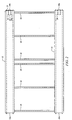
- Fig. 2 depicts a pair of said hollow cylinders 12 disposed in transversely spaced apart, parallel relation to one another. Said cylinders are interconnected to one another along their respective extents by a plurality of transversely disposed, longitudinally spaced apart diaphragm members, collectively denoted 19.
- an imperforate circular disc 20 is positioned within the lumen of each hollow cylinder 12 in perpendicular relation to the longitudinal axis of symmetry of said hollow cylinder.
- a first circular disc 22 having a central opening 23 formed therein is secured to a first end of hollow cylinder 12.
- a second circular disc 22a having a central opening 23a that forms a key-receiving socket is secured to a second, opposite end of hollow cylinder 12 in closing relation thereto.
- No reference numeral is provided for central openings 23 and 23a in Fig. 2 to avoid cluttering of the drawings.
- Truncate hollow cylinder member 24 has a first end 24a secured to imperforate circular disc 20 in concentric relation thereto, i.e., truncate cylindrical member 24 has the same longitudinal axis of symmetry as does elongate hollow cylinder 12. Second end 24b of truncate cylindrical member 24 extends through the central opening formed in first circular disc 22. The protrusion of second end 24b forms a key or pin that mates with the key-receiving socket formed in second cylindrical disc 22a when two (2) cylindrical members 12 are disposed in end-to-end abutting relation to one another along a common longitudinal axis of symmetry.
- each elongate hollow cylinder 12 is provided with key or pin 24b as depicted in Fig. 2 and the second or trailing end of each elongate hollow cylinder is provided with a key-receiving socket in the form of said central opening formed in second circular disc 22a.
- the first and second centrally apertured circular discs 22 and 22a, respectively, have the same structure.
- the difference in reference numerals merely points out their difference in positions at opposite ends of each elongate hollow cylinder.
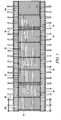
- Fig. 3 depicts a plurality of longitudinally-disposed timbers, collectively denoted 26, supported by said transversely disposed diaphragms 19.
- Timbers 26 collectively form a timber mat that provides a roadway for heavy equipment.
- all prior art timber mats are formed by a plurality of transversely disposed timbers which are supported by longitudinally disposed diaphragms which are in turn supported by transversely disposed diaphragms.
- the novel arrangement of Fig. 3 thus eliminates the longitudinally disposed diaphragms of the prior art.
- each diaphragm 19 is connected at its opposite ends to a flat brace 21 that is welded to its associated hollow cylinder 12 in a vertical plane.
- the cylinder-abutting side of each brace 21 is arcuate to conform to the surface of its associated hollow cylinder.
- a plurality of openings, collectively denoted 28, is formed in each brace 21 along its outboard edges and each diaphragm 19 has a plurality of openings formed in each of its ends which can be aligned with preselected openings 28. Suitable nuts and bolts are used to secure the opposite ends of each diaphragm 19 to its associated brace 21.
- Such structure allows height adjustment of each diaphragm 19 along the vertical extent of its associated brace 21 and thus height adjustment of the timber mat supported by said diaphragms.
- the timber mat in Fig. 4B is elevated with respect to the timber mat depicted in Fig. 4A .
- the Fig. 4B timber mat is a prior art timber mat having transversely disposed timbers.
- a pedestrian walkway is supported by a plurality of transversely disposed, longitudinally spaced apart boards, collectively denoted 30, that are mounted atop and secured to rigid flat top plate 16 in cantilever relation thereto and which extend in an outboard direction relative to each hollow cylinder 12.
- Elongate strips of plywood 32 or other suitable material overlie boards 30 and provide support for a pedestrian.
- such a pedestrian walkway is provided on the outboard side of each hollow cylinder.
- An upstanding safety hand rail 34 is provided on the outboard side of each walkway and a longitudinally disposed timber 26a that is smaller than a timber mat timber 26 may be used to provide a guiding curb for the equipment as depicted in said Fig. 4A . Still smaller timbers 26b are used to support plywood 32.
- Figs. 3 and 4A also disclose transversely disposed shorter boards 30a directly overlying upper rigid flat plate 16 of their associated hollow cylinder 12 and filling in the spaces between the longer, cantilevered boards 30.
- the transverse spacing of piles 13 that support hollow cylinders 12 may be selected to directly support treads 11 of a crane 15 or other item of heavy equipment.
- a pedestrian walkway may also be provided as disclosed in Fig. 4B .
- transversely disposed, cantilevered boards 30 and the shorter boards 30a therebetween are not used.
- a plurality of transversely disposed, longitudinally spaced apart elongate timber mats 27, only one of which is depicted in the end view of Fig. 4B is mounted and secured to the rigid flat mounting plate 16 that surmounts each hollow cylinder 12.
- Each of said timber mats 27 has a transverse extent that exceeds the distance between the transversely spaced apart hollow cylinders 12.
- each transverse timber mat 27 extends outboard of the hollow cylinders defines the width of each pedestrian walkway.
- a longitudinally extending strip of plywood 32 fills in the gap between timbers 27 to provide a pedestrian walkway and a suitable safety handrail may be provided as well.
- FIG. 5 The structure that enables the novel temporary bridge to turn relative to a straight line is depicted in Figs. 5 and Figs. 6A-D .
- Fig. 5 depicts novel turn-creating member 40 and its position between two end-to-end elongate hollow cylinders 12. Note that no such turn or curve-creating member 40 is provided between the transversely spaced associated elongate hollow cylinders 12 that are disposed end-to-end because such elongate hollow cylinders follow the interior curvature of the turn or curve and thus are not as widely spaced apart as are the elongate hollow cylinders on the outboard side of the curve.
- Turn-creating member 40 is hereinafter referred to as the first or outer truncate hollow cylinder. It has a diameter equal to the diameter of each elongate hollow cylinder 12 and a structure that is much the same as the structure as each elongate hollow cylinder.
- Figs. 6A-D respectively provide top plan, first side, second side, and end views of turn or curve-creating outer truncate hollow cylinder 40.
- Fig. 5 may be interpreted as depicting a turn to the left in the novel temporary bridge structure. Accordingly, the upwardly inclined (as drawn) second or inner truncate hollow cylinder 24 depicted in the top plan view of Fig. 5 and in enlarged view in Fig. 6A indicates such left turn.
- first centrally-apertured circular disc 22 is disposed at an obtuse angle in Fig. 6A relative to a horizontal plane, and the left side 40a of member 40 has a shorter extent than right side 40b thereof.
- said left and right sides 40a, 40b are inclined upwardly from a horizontal plane as depicted in said Fig. 6A .
- a member 40 for creating a right turn would include a downwardly tilted inner truncate hollow cylinder 24 in Fig. 6A and the respective lengths and inclinations of sides 40a and 40b would be reversed.
- each member 40 has a socket opening 23a formed in each centrally-apertured circular disc 22 and 22a and a key 24b that protrudes through the central opening formed in each first centrally-apertured circular disc 22.
- first or outer truncate hollow cylinder 40 is truncate relative to said elongate hollow cylinders 12, and said first truncate hollow cylinder 40 has a diameter substantially equal to a diameter of each elongate hollow cylinder 12.
- a second or inner truncate hollow cylinder 24 is disposed concentrically within said first truncate hollow cylinder 40 and has a longitudinal axis of symmetry disposed at a predetermined angle relative to a longitudinal axis of symmetry of said first truncate hollow cylinder 40. Said second truncate hollow cylinder 24 therefore has a leading end disposed in oblique relation to a trailing end of said second truncate hollow cylinder.
- First truncate hollow cylinder 40 is positioned between two elongate hollow cylinders 12 disposed in end-to-end relation to one another, one of which is a leading elongate hollow cylinder and one of which is a trailing elongate hollow cylinder.
- the trailing elongate hollow cylinder is in axial alignment with a trailing end of said first or outer truncate hollow cylinder 40 and said leading elongate hollow cylinder is in axial alignment with a leading end of said second or inner truncate hollow cylinder 24.
- the predetermined angle of said second truncate hollow cylinder 24 enables construction of a temporary bridge having at least two straight sections that form an angle with one another equal to the predetermined angle of said second truncate hollow cylinder 24 with respect to the longitudinal axis of symmetry of said first truncate hollow cylinder 40.
- first or outer truncate hollow cylinder 40 is the same as each elongate hollow cylinder 12.
- An imperforate circular disc 20 is positioned within a lumen of first truncate hollow cylinder 40 in parallel relation to a trailing end of said first truncate hollow cylinder and in spaced apart relation to the leading end of said first truncate hollow cylinder.
- a first circular disc 22 having a central opening formed therein is secured to the leading end of first truncate hollow cylinder 40 and a second circular disc 22a having a central opening that forms a key-receiving socket is secured to the trailing end of said first truncate hollow cylinder 40 in closing relation thereto.
- Second or inner truncate hollow cylinder member 24 has a trailing end secured to said imperforate circular disc 20 in concentric relation thereto and a leading end protruding through the central opening formed in first centrally-apertured circular disc 22. The leading forms a key that engages said key-receiving socket.
- Fig. 7 depicts an elongate hollow cylinder 12 having flat top plate 16 secured thereto in a horizontal plane and flat bottom plate 18 secured thereto in a horizontal plane.
- Top flat plate 16 makes tangential contact as at 16a with hollow cylinder 12 at the twelve o'clock position of the circle defined by said hollow cylinder 12 in end view and bottom flat plate 18 makes tangential contact as at 18a with hollow cylinder 12 at the six o'clock position of the circle.
- Upper strengthening members 14a, 14a are formed integrally with or welded to flat top plate 16 and depend therefrom in normal relation thereto.
- Lower strengthening members 14b, 14b are formed integrally with or welded to flat bottom plate 18 and project upwardly therefrom in normal relation thereto.
- Upper strengthening members 14a, 14a are positioned on opposite sides of the twelve o'clock point of tangential contact 16a in equidistantly spaced relation to said twelve o'clock point of tangential contact.
- Lower strengthening members 14b, 14b are positioned on opposite sides of the sic o'clock point of tangential contact 18a in equidistantly spaced relation to said six o'clock point of tangential contact.
- This reference example has the advantage of providing substantially as much strengthening as the above-disclosed embodiment with less materials in that each strengthening member has one leg instead of two. It has the disadvantage of requiring a more precise placement of legs 14a, 14a, 14b, 14b relative to the placement of the two leg embodiment because there are only four points of strengthening contact instead of eight.
Landscapes
- Engineering & Computer Science (AREA)
- Architecture (AREA)
- Civil Engineering (AREA)
- Structural Engineering (AREA)
- Bridges Or Land Bridges (AREA)
Priority Applications (1)
| Application Number | Priority Date | Filing Date | Title |
|---|---|---|---|
| PL14867128T PL3077596T3 (pl) | 2013-12-03 | 2014-12-02 | Struktura nośna tymczasowego mostu |
Applications Claiming Priority (3)
| Application Number | Priority Date | Filing Date | Title |
|---|---|---|---|
| US14/095,298 US9228301B2 (en) | 2013-12-03 | 2013-12-03 | Elongate pipe-based structure for supporting heavy loads |
| US14/169,781 US9228302B2 (en) | 2013-12-03 | 2014-01-31 | Elongate pipe-based temporary bridge for supporting heavy loads |
| PCT/US2014/068051 WO2015084785A1 (en) | 2013-12-03 | 2014-12-02 | Elongate pipe-based temporary bridge for supporting heavy loads |
Publications (3)
| Publication Number | Publication Date |
|---|---|
| EP3077596A1 EP3077596A1 (en) | 2016-10-12 |
| EP3077596A4 EP3077596A4 (en) | 2017-12-20 |
| EP3077596B1 true EP3077596B1 (en) | 2020-02-05 |
Family
ID=53264884
Family Applications (1)
| Application Number | Title | Priority Date | Filing Date |
|---|---|---|---|
| EP14867128.2A Active EP3077596B1 (en) | 2013-12-03 | 2014-12-02 | Support structure for a temporary bridge |
Country Status (5)
| Country | Link |
|---|---|
| US (1) | US9228302B2 (pl) |
| EP (1) | EP3077596B1 (pl) |
| CA (1) | CA2932104C (pl) |
| PL (1) | PL3077596T3 (pl) |
| WO (1) | WO2015084785A1 (pl) |
Families Citing this family (1)
| Publication number | Priority date | Publication date | Assignee | Title |
|---|---|---|---|---|
| JP2024079291A (ja) * | 2022-11-30 | 2024-06-11 | 株式会社高知丸高 | 橋梁の施工方法及びその橋梁 |
Family Cites Families (7)
| Publication number | Priority date | Publication date | Assignee | Title |
|---|---|---|---|---|
| JPH05118134A (ja) * | 1991-10-25 | 1993-05-14 | Fudo Constr Co Ltd | 柱型枠装置 |
| JP4351593B2 (ja) * | 2004-07-21 | 2009-10-28 | 株式会社技研製作所 | フランジ付鋼管矢板及びその構造物 |
| US8573556B1 (en) * | 2005-10-18 | 2013-11-05 | Verti-Crete, Llc | Vertical concrete column form and method of forming same |
| KR100732701B1 (ko) * | 2005-12-13 | 2007-06-27 | (주)씨디텍엔지니어링 | 원형강관을 이용한 가설시스템 |
| KR20090041620A (ko) * | 2007-10-24 | 2009-04-29 | 주식회사 스틸코리아 | 상부강재빔이 형성된 주형을 이용한 가설교량 설치구조 및그 시공방법 |
| KR101229472B1 (ko) | 2011-11-16 | 2013-02-07 | 한우물중공업 주식회사 | 교량용 강관 거더 |
| KR101329440B1 (ko) | 2013-04-22 | 2013-11-14 | 주식회사 포스코 | 연결용 엔클로저를 포함하는 강관버팀보 |
-
2014
- 2014-01-31 US US14/169,781 patent/US9228302B2/en active Active
- 2014-12-02 EP EP14867128.2A patent/EP3077596B1/en active Active
- 2014-12-02 WO PCT/US2014/068051 patent/WO2015084785A1/en not_active Ceased
- 2014-12-02 PL PL14867128T patent/PL3077596T3/pl unknown
- 2014-12-02 CA CA2932104A patent/CA2932104C/en active Active
Non-Patent Citations (1)
| Title |
|---|
| None * |
Also Published As
| Publication number | Publication date |
|---|---|
| WO2015084785A9 (en) | 2016-05-06 |
| US9228302B2 (en) | 2016-01-05 |
| CA2932104A1 (en) | 2015-06-11 |
| PL3077596T3 (pl) | 2020-07-13 |
| CA2932104C (en) | 2020-04-14 |
| EP3077596A4 (en) | 2017-12-20 |
| US20150152608A1 (en) | 2015-06-04 |
| WO2015084785A1 (en) | 2015-06-11 |
| EP3077596A1 (en) | 2016-10-12 |
Similar Documents
| Publication | Publication Date | Title |
|---|---|---|
| KR102085143B1 (ko) | 프리캐스트 콘크리트 더블월식 합성 콘크리트 구조물 및 이의 시공 방법 | |
| US10907312B2 (en) | Road form work | |
| CN108755442A (zh) | 用于大型钢构件高空安装的导向与定位装置 | |
| US8496397B2 (en) | Precast concrete slabs and related systems, methods of manufacture and installation | |
| JP2007040020A (ja) | Pc箱桁橋の架設方法 | |
| KR102080492B1 (ko) | 거더교의 캔틸레버 시공 방법 | |
| CN204589751U (zh) | 装配式临时道路结构 | |
| EP3077596B1 (en) | Support structure for a temporary bridge | |
| KR101761477B1 (ko) | 적층형 토목섬유 보강토지반벽체와 스프레드 토대판을 사용한 무조인트교량 시공방법 | |
| KR20080114297A (ko) | 소하천 아치 교량 및 그 시공방법 | |
| KR101439947B1 (ko) | 링플레이트가 장착된 원형 거더와 횡방향 브라켓을 이용한 교량 및 그 시공방법 | |
| US9834896B1 (en) | Elongate pipe-based support structure | |
| JP2019078065A (ja) | 片持ちばり式擁壁の敷設方法 | |
| US10689811B2 (en) | System, apparatus and related method for raised ground cover mat | |
| CN102454298B (zh) | 大型钢筋混凝土框架梁施工方法 | |
| JP7239356B2 (ja) | 道路橋のコンクリート床板取替工法 | |
| KR200272863Y1 (ko) | 보차도 경계석 시공용 거푸집 | |
| JP5345238B1 (ja) | 免震基礎構造物の構築方法および免震基礎構造物 | |
| JP6782492B2 (ja) | 仮橋及び仮橋の施工方法 | |
| KR100421730B1 (ko) | 파형강판 구조물의 시공방법 | |
| US20160326703A1 (en) | Adjustable telescopic formwork for paving with linear or axial and radial geometric alignment | |
| US9228301B2 (en) | Elongate pipe-based structure for supporting heavy loads | |
| KR101920789B1 (ko) | 하부기초 보강용 구조물의 세굴방지공 | |
| KR101653559B1 (ko) | 철도 교량의 유도상화 공법 | |
| JP2005240488A (ja) | プレキャストコンクリート橋の解体方法 |
Legal Events
| Date | Code | Title | Description |
|---|---|---|---|
| PUAI | Public reference made under article 153(3) epc to a published international application that has entered the european phase |
Free format text: ORIGINAL CODE: 0009012 |
|
| 17P | Request for examination filed |
Effective date: 20160617 |
|
| AK | Designated contracting states |
Kind code of ref document: A1 Designated state(s): AL AT BE BG CH CY CZ DE DK EE ES FI FR GB GR HR HU IE IS IT LI LT LU LV MC MK MT NL NO PL PT RO RS SE SI SK SM TR |
|
| AX | Request for extension of the european patent |
Extension state: BA ME |
|
| DAX | Request for extension of the european patent (deleted) | ||
| A4 | Supplementary search report drawn up and despatched |
Effective date: 20171117 |
|
| RIC1 | Information provided on ipc code assigned before grant |
Ipc: E01D 15/12 20060101AFI20171113BHEP |
|
| STAA | Information on the status of an ep patent application or granted ep patent |
Free format text: STATUS: EXAMINATION IS IN PROGRESS |
|
| 17Q | First examination report despatched |
Effective date: 20181004 |
|
| GRAP | Despatch of communication of intention to grant a patent |
Free format text: ORIGINAL CODE: EPIDOSNIGR1 |
|
| STAA | Information on the status of an ep patent application or granted ep patent |
Free format text: STATUS: GRANT OF PATENT IS INTENDED |
|
| INTG | Intention to grant announced |
Effective date: 20190712 |
|
| GRAS | Grant fee paid |
Free format text: ORIGINAL CODE: EPIDOSNIGR3 |
|
| GRAA | (expected) grant |
Free format text: ORIGINAL CODE: 0009210 |
|
| STAA | Information on the status of an ep patent application or granted ep patent |
Free format text: STATUS: THE PATENT HAS BEEN GRANTED |
|
| AK | Designated contracting states |
Kind code of ref document: B1 Designated state(s): AL AT BE BG CH CY CZ DE DK EE ES FI FR GB GR HR HU IE IS IT LI LT LU LV MC MK MT NL NO PL PT RO RS SE SI SK SM TR |
|
| REG | Reference to a national code |
Ref country code: GB Ref legal event code: FG4D |
|
| REG | Reference to a national code |
Ref country code: AT Ref legal event code: REF Ref document number: 1229981 Country of ref document: AT Kind code of ref document: T Effective date: 20200215 |
|
| REG | Reference to a national code |
Ref country code: DE Ref legal event code: R096 Ref document number: 602014060712 Country of ref document: DE |
|
| REG | Reference to a national code |
Ref country code: IE Ref legal event code: FG4D |
|
| REG | Reference to a national code |
Ref country code: CH Ref legal event code: EP |
|
| REG | Reference to a national code |
Ref country code: NL Ref legal event code: FP |
|
| PG25 | Lapsed in a contracting state [announced via postgrant information from national office to epo] |
Ref country code: RS Free format text: LAPSE BECAUSE OF FAILURE TO SUBMIT A TRANSLATION OF THE DESCRIPTION OR TO PAY THE FEE WITHIN THE PRESCRIBED TIME-LIMIT Effective date: 20200205 Ref country code: FI Free format text: LAPSE BECAUSE OF FAILURE TO SUBMIT A TRANSLATION OF THE DESCRIPTION OR TO PAY THE FEE WITHIN THE PRESCRIBED TIME-LIMIT Effective date: 20200205 Ref country code: PT Free format text: LAPSE BECAUSE OF FAILURE TO SUBMIT A TRANSLATION OF THE DESCRIPTION OR TO PAY THE FEE WITHIN THE PRESCRIBED TIME-LIMIT Effective date: 20200628 Ref country code: NO Free format text: LAPSE BECAUSE OF FAILURE TO SUBMIT A TRANSLATION OF THE DESCRIPTION OR TO PAY THE FEE WITHIN THE PRESCRIBED TIME-LIMIT Effective date: 20200505 |
|
| REG | Reference to a national code |
Ref country code: LT Ref legal event code: MG4D |
|
| PG25 | Lapsed in a contracting state [announced via postgrant information from national office to epo] |
Ref country code: IS Free format text: LAPSE BECAUSE OF FAILURE TO SUBMIT A TRANSLATION OF THE DESCRIPTION OR TO PAY THE FEE WITHIN THE PRESCRIBED TIME-LIMIT Effective date: 20200605 Ref country code: BG Free format text: LAPSE BECAUSE OF FAILURE TO SUBMIT A TRANSLATION OF THE DESCRIPTION OR TO PAY THE FEE WITHIN THE PRESCRIBED TIME-LIMIT Effective date: 20200505 Ref country code: HR Free format text: LAPSE BECAUSE OF FAILURE TO SUBMIT A TRANSLATION OF THE DESCRIPTION OR TO PAY THE FEE WITHIN THE PRESCRIBED TIME-LIMIT Effective date: 20200205 Ref country code: GR Free format text: LAPSE BECAUSE OF FAILURE TO SUBMIT A TRANSLATION OF THE DESCRIPTION OR TO PAY THE FEE WITHIN THE PRESCRIBED TIME-LIMIT Effective date: 20200506 Ref country code: SE Free format text: LAPSE BECAUSE OF FAILURE TO SUBMIT A TRANSLATION OF THE DESCRIPTION OR TO PAY THE FEE WITHIN THE PRESCRIBED TIME-LIMIT Effective date: 20200205 Ref country code: LV Free format text: LAPSE BECAUSE OF FAILURE TO SUBMIT A TRANSLATION OF THE DESCRIPTION OR TO PAY THE FEE WITHIN THE PRESCRIBED TIME-LIMIT Effective date: 20200205 |
|
| PG25 | Lapsed in a contracting state [announced via postgrant information from national office to epo] |
Ref country code: DK Free format text: LAPSE BECAUSE OF FAILURE TO SUBMIT A TRANSLATION OF THE DESCRIPTION OR TO PAY THE FEE WITHIN THE PRESCRIBED TIME-LIMIT Effective date: 20200205 Ref country code: EE Free format text: LAPSE BECAUSE OF FAILURE TO SUBMIT A TRANSLATION OF THE DESCRIPTION OR TO PAY THE FEE WITHIN THE PRESCRIBED TIME-LIMIT Effective date: 20200205 Ref country code: SM Free format text: LAPSE BECAUSE OF FAILURE TO SUBMIT A TRANSLATION OF THE DESCRIPTION OR TO PAY THE FEE WITHIN THE PRESCRIBED TIME-LIMIT Effective date: 20200205 Ref country code: RO Free format text: LAPSE BECAUSE OF FAILURE TO SUBMIT A TRANSLATION OF THE DESCRIPTION OR TO PAY THE FEE WITHIN THE PRESCRIBED TIME-LIMIT Effective date: 20200205 Ref country code: CZ Free format text: LAPSE BECAUSE OF FAILURE TO SUBMIT A TRANSLATION OF THE DESCRIPTION OR TO PAY THE FEE WITHIN THE PRESCRIBED TIME-LIMIT Effective date: 20200205 Ref country code: SK Free format text: LAPSE BECAUSE OF FAILURE TO SUBMIT A TRANSLATION OF THE DESCRIPTION OR TO PAY THE FEE WITHIN THE PRESCRIBED TIME-LIMIT Effective date: 20200205 Ref country code: LT Free format text: LAPSE BECAUSE OF FAILURE TO SUBMIT A TRANSLATION OF THE DESCRIPTION OR TO PAY THE FEE WITHIN THE PRESCRIBED TIME-LIMIT Effective date: 20200205 Ref country code: ES Free format text: LAPSE BECAUSE OF FAILURE TO SUBMIT A TRANSLATION OF THE DESCRIPTION OR TO PAY THE FEE WITHIN THE PRESCRIBED TIME-LIMIT Effective date: 20200205 |
|
| REG | Reference to a national code |
Ref country code: DE Ref legal event code: R097 Ref document number: 602014060712 Country of ref document: DE |
|
| REG | Reference to a national code |
Ref country code: AT Ref legal event code: MK05 Ref document number: 1229981 Country of ref document: AT Kind code of ref document: T Effective date: 20200205 |
|
| PLBE | No opposition filed within time limit |
Free format text: ORIGINAL CODE: 0009261 |
|
| STAA | Information on the status of an ep patent application or granted ep patent |
Free format text: STATUS: NO OPPOSITION FILED WITHIN TIME LIMIT |
|
| 26N | No opposition filed |
Effective date: 20201106 |
|
| PG25 | Lapsed in a contracting state [announced via postgrant information from national office to epo] |
Ref country code: AT Free format text: LAPSE BECAUSE OF FAILURE TO SUBMIT A TRANSLATION OF THE DESCRIPTION OR TO PAY THE FEE WITHIN THE PRESCRIBED TIME-LIMIT Effective date: 20200205 |
|
| PG25 | Lapsed in a contracting state [announced via postgrant information from national office to epo] |
Ref country code: SI Free format text: LAPSE BECAUSE OF FAILURE TO SUBMIT A TRANSLATION OF THE DESCRIPTION OR TO PAY THE FEE WITHIN THE PRESCRIBED TIME-LIMIT Effective date: 20200205 |
|
| PG25 | Lapsed in a contracting state [announced via postgrant information from national office to epo] |
Ref country code: MC Free format text: LAPSE BECAUSE OF FAILURE TO SUBMIT A TRANSLATION OF THE DESCRIPTION OR TO PAY THE FEE WITHIN THE PRESCRIBED TIME-LIMIT Effective date: 20200205 |
|
| PG25 | Lapsed in a contracting state [announced via postgrant information from national office to epo] |
Ref country code: IE Free format text: LAPSE BECAUSE OF NON-PAYMENT OF DUE FEES Effective date: 20201202 |
|
| PG25 | Lapsed in a contracting state [announced via postgrant information from national office to epo] |
Ref country code: MT Free format text: LAPSE BECAUSE OF FAILURE TO SUBMIT A TRANSLATION OF THE DESCRIPTION OR TO PAY THE FEE WITHIN THE PRESCRIBED TIME-LIMIT Effective date: 20200205 Ref country code: CY Free format text: LAPSE BECAUSE OF FAILURE TO SUBMIT A TRANSLATION OF THE DESCRIPTION OR TO PAY THE FEE WITHIN THE PRESCRIBED TIME-LIMIT Effective date: 20200205 |
|
| PG25 | Lapsed in a contracting state [announced via postgrant information from national office to epo] |
Ref country code: MK Free format text: LAPSE BECAUSE OF FAILURE TO SUBMIT A TRANSLATION OF THE DESCRIPTION OR TO PAY THE FEE WITHIN THE PRESCRIBED TIME-LIMIT Effective date: 20200205 Ref country code: AL Free format text: LAPSE BECAUSE OF FAILURE TO SUBMIT A TRANSLATION OF THE DESCRIPTION OR TO PAY THE FEE WITHIN THE PRESCRIBED TIME-LIMIT Effective date: 20200205 |
|
| P01 | Opt-out of the competence of the unified patent court (upc) registered |
Effective date: 20230601 |
|
| REG | Reference to a national code |
Ref country code: CH Ref legal event code: U11 Free format text: ST27 STATUS EVENT CODE: U-0-0-U10-U11 (AS PROVIDED BY THE NATIONAL OFFICE) Effective date: 20260101 |
|
| PGFP | Annual fee paid to national office [announced via postgrant information from national office to epo] |
Ref country code: GB Payment date: 20251208 Year of fee payment: 12 |
|
| PGFP | Annual fee paid to national office [announced via postgrant information from national office to epo] |
Ref country code: IT Payment date: 20251212 Year of fee payment: 12 |
|
| PGFP | Annual fee paid to national office [announced via postgrant information from national office to epo] |
Ref country code: LU Payment date: 20251204 Year of fee payment: 12 Ref country code: FR Payment date: 20251217 Year of fee payment: 12 Ref country code: NL Payment date: 20251210 Year of fee payment: 12 |
|
| PGFP | Annual fee paid to national office [announced via postgrant information from national office to epo] |
Ref country code: TR Payment date: 20251129 Year of fee payment: 12 Ref country code: BE Payment date: 20251208 Year of fee payment: 12 |
|
| PGFP | Annual fee paid to national office [announced via postgrant information from national office to epo] |
Ref country code: PL Payment date: 20251124 Year of fee payment: 12 |
|
| PGFP | Annual fee paid to national office [announced via postgrant information from national office to epo] |
Ref country code: DE Payment date: 20251222 Year of fee payment: 12 |
|
| PGFP | Annual fee paid to national office [announced via postgrant information from national office to epo] |
Ref country code: CH Payment date: 20260101 Year of fee payment: 12 |