EP3077121B1 - Verfahren zum aufbringen einer dünnen beschichtung auf eine grossflächige oberfläche - Google Patents
Verfahren zum aufbringen einer dünnen beschichtung auf eine grossflächige oberfläche Download PDFInfo
- Publication number
- EP3077121B1 EP3077121B1 EP14865277.9A EP14865277A EP3077121B1 EP 3077121 B1 EP3077121 B1 EP 3077121B1 EP 14865277 A EP14865277 A EP 14865277A EP 3077121 B1 EP3077121 B1 EP 3077121B1
- Authority
- EP
- European Patent Office
- Prior art keywords
- coating
- deposition
- droplet
- coating material
- materials
- Prior art date
- Legal status (The legal status is an assumption and is not a legal conclusion. Google has not performed a legal analysis and makes no representation as to the accuracy of the status listed.)
- Not-in-force
Links
Images


Classifications
-
- B—PERFORMING OPERATIONS; TRANSPORTING
- B41—PRINTING; LINING MACHINES; TYPEWRITERS; STAMPS
- B41J—TYPEWRITERS; SELECTIVE PRINTING MECHANISMS, i.e. MECHANISMS PRINTING OTHERWISE THAN FROM A FORME; CORRECTION OF TYPOGRAPHICAL ERRORS
- B41J11/00—Devices or arrangements of selective printing mechanisms, e.g. ink-jet printers or thermal printers, for supporting or handling copy material in sheet or web form
- B41J11/0015—Devices or arrangements of selective printing mechanisms, e.g. ink-jet printers or thermal printers, for supporting or handling copy material in sheet or web form for treating before, during or after printing or for uniform coating or laminating the copy material before or after printing
-
- C—CHEMISTRY; METALLURGY
- C09—DYES; PAINTS; POLISHES; NATURAL RESINS; ADHESIVES; COMPOSITIONS NOT OTHERWISE PROVIDED FOR; APPLICATIONS OF MATERIALS NOT OTHERWISE PROVIDED FOR
- C09D—COATING COMPOSITIONS, e.g. PAINTS, VARNISHES OR LACQUERS; FILLING PASTES; CHEMICAL PAINT OR INK REMOVERS; INKS; CORRECTING FLUIDS; WOODSTAINS; PASTES OR SOLIDS FOR COLOURING OR PRINTING; USE OF MATERIALS THEREFOR
- C09D175/00—Coating compositions based on polyureas or polyurethanes; Coating compositions based on derivatives of such polymers
- C09D175/04—Polyurethanes
-
- B—PERFORMING OPERATIONS; TRANSPORTING
- B05—SPRAYING OR ATOMISING IN GENERAL; APPLYING FLUENT MATERIALS TO SURFACES, IN GENERAL
- B05D—PROCESSES FOR APPLYING FLUENT MATERIALS TO SURFACES, IN GENERAL
- B05D1/00—Processes for applying liquids or other fluent materials
- B05D1/28—Processes for applying liquids or other fluent materials performed by transfer from the surfaces of elements carrying the liquid or other fluent material, e.g. brushes, pads, rollers
-
- B—PERFORMING OPERATIONS; TRANSPORTING
- B05—SPRAYING OR ATOMISING IN GENERAL; APPLYING FLUENT MATERIALS TO SURFACES, IN GENERAL
- B05D—PROCESSES FOR APPLYING FLUENT MATERIALS TO SURFACES, IN GENERAL
- B05D1/00—Processes for applying liquids or other fluent materials
- B05D1/34—Applying different liquids or other fluent materials simultaneously
-
- B—PERFORMING OPERATIONS; TRANSPORTING
- B05—SPRAYING OR ATOMISING IN GENERAL; APPLYING FLUENT MATERIALS TO SURFACES, IN GENERAL
- B05D—PROCESSES FOR APPLYING FLUENT MATERIALS TO SURFACES, IN GENERAL
- B05D3/00—Pretreatment of surfaces to which liquids or other fluent materials are to be applied; After-treatment of applied coatings, e.g. intermediate treating of an applied coating preparatory to subsequent applications of liquids or other fluent materials
- B05D3/02—Pretreatment of surfaces to which liquids or other fluent materials are to be applied; After-treatment of applied coatings, e.g. intermediate treating of an applied coating preparatory to subsequent applications of liquids or other fluent materials by baking
- B05D3/0218—Pretreatment, e.g. heating the substrate
-
- B—PERFORMING OPERATIONS; TRANSPORTING
- B05—SPRAYING OR ATOMISING IN GENERAL; APPLYING FLUENT MATERIALS TO SURFACES, IN GENERAL
- B05D—PROCESSES FOR APPLYING FLUENT MATERIALS TO SURFACES, IN GENERAL
- B05D3/00—Pretreatment of surfaces to which liquids or other fluent materials are to be applied; After-treatment of applied coatings, e.g. intermediate treating of an applied coating preparatory to subsequent applications of liquids or other fluent materials
- B05D3/02—Pretreatment of surfaces to which liquids or other fluent materials are to be applied; After-treatment of applied coatings, e.g. intermediate treating of an applied coating preparatory to subsequent applications of liquids or other fluent materials by baking
- B05D3/0254—After-treatment
-
- B—PERFORMING OPERATIONS; TRANSPORTING
- B05—SPRAYING OR ATOMISING IN GENERAL; APPLYING FLUENT MATERIALS TO SURFACES, IN GENERAL
- B05B—SPRAYING APPARATUS; ATOMISING APPARATUS; NOZZLES
- B05B1/00—Nozzles, spray heads or other outlets, with or without auxiliary devices such as valves, heating means
- B05B1/14—Nozzles, spray heads or other outlets, with or without auxiliary devices such as valves, heating means with multiple outlet openings; with strainers in or outside the outlet opening
-
- B—PERFORMING OPERATIONS; TRANSPORTING
- B05—SPRAYING OR ATOMISING IN GENERAL; APPLYING FLUENT MATERIALS TO SURFACES, IN GENERAL
- B05B—SPRAYING APPARATUS; ATOMISING APPARATUS; NOZZLES
- B05B13/00—Machines or plants for applying liquids or other fluent materials to surfaces of objects or other work by spraying, not covered by groups B05B1/00 - B05B11/00
- B05B13/02—Means for supporting work; Arrangement or mounting of spray heads; Adaptation or arrangement of means for feeding work
- B05B13/04—Means for supporting work; Arrangement or mounting of spray heads; Adaptation or arrangement of means for feeding work the spray heads being moved during spraying operation
- B05B13/0447—Installation or apparatus for applying liquid or other fluent material to conveyed separate articles
-
- B—PERFORMING OPERATIONS; TRANSPORTING
- B05—SPRAYING OR ATOMISING IN GENERAL; APPLYING FLUENT MATERIALS TO SURFACES, IN GENERAL
- B05D—PROCESSES FOR APPLYING FLUENT MATERIALS TO SURFACES, IN GENERAL
- B05D2252/00—Sheets
-
- B—PERFORMING OPERATIONS; TRANSPORTING
- B05—SPRAYING OR ATOMISING IN GENERAL; APPLYING FLUENT MATERIALS TO SURFACES, IN GENERAL
- B05D—PROCESSES FOR APPLYING FLUENT MATERIALS TO SURFACES, IN GENERAL
- B05D5/00—Processes for applying liquids or other fluent materials to surfaces to obtain special surface effects, finishes or structures
-
- B—PERFORMING OPERATIONS; TRANSPORTING
- B41—PRINTING; LINING MACHINES; TYPEWRITERS; STAMPS
- B41J—TYPEWRITERS; SELECTIVE PRINTING MECHANISMS, i.e. MECHANISMS PRINTING OTHERWISE THAN FROM A FORME; CORRECTION OF TYPOGRAPHICAL ERRORS
- B41J2/00—Typewriters or selective printing mechanisms characterised by the printing or marking process for which they are designed
- B41J2/005—Typewriters or selective printing mechanisms characterised by the printing or marking process for which they are designed characterised by bringing liquid or particles selectively into contact with a printing material
- B41J2/01—Ink jet
- B41J2/135—Nozzles
- B41J2/14—Structure thereof only for on-demand ink jet heads
- B41J2/1433—Structure of nozzle plates
Definitions
- Coating of boards or panels is known in the art.
- the coating is required to be thin and homogenous.
- Some known methods for applying thin coating include submerging of the panel in a container containing a fluidic coating material and allowing the fluid to drip off the panel by virtue of gravity (or other similar methods) after the panel is taken out of the container.
- Another known method involves spray application. This method can be applied with a spray aerosol or dedicated spray booth with spray gun. The quality of the surface finish can be better than all other methods when a trained skilled operator completes the process, as long as the substrate is clean and the coating has no adhesion issues.
- the coating application may be limited due to 3D effects, and its homogeneity is very hard to achieve.
- the known methods suffer of various drawbacks such as poor homogeneity, too thick coating which deteriorates the quality of transparency of the coated board and deteriorate the strength of the coating layer; for relatively mid-scale panels moving over to a facility other than that where the panels are produced is required; long application of the time coating layer is required, from beginning to a point where the coated panel may be moved over, etc.
- US 2010/0221449 A1 discloses an apparatus for applying coatings to surfaces of substrates in the form of paper, cardboard or plastic films, preferably for finishing printed materials.
- US 2013/0122206 A1 discloses a mobile coating system for coating an electrical insulator, including an elongate shipping container that is transportable to a worksite.
- US 5,266,349 discloses a method of discrete conformal coating, comprising pressurizing the coating, longitudinally advancing a surface to be coated, while simultaneously feeding the coating onto the surface.
- US 2009/0252878 A1 discloses a coating method in which a coating liquid is continuously supplied from a supply head to a surface of a continuously travelling sheet-like substrate to form a coat while controlling its thickness by a coating bar disposed above the sheet-like substrate.
- US 2003/0161964 A1 discloses a system and method for forming continuous void-free uniform coatings on filamentous articles by applying a voided or otherwise substantially uneven coating to at least a some of the exposed portion of a filamentous article or to a rotating substrate.
- JP 2000153182 A discloses a spray coating system comprising a spray head equipped with a first coating ejecting nozzle for ejecting a first coating material, an air ejecting nozzle for ejecting air which is installed around the first coating ejecting nozzle, and a second coating ejecting nozzle for ejecting a second coating material which is installed around the air ejecting nozzle.
- US 2005/0255249 A1 discloses a method and apparatus for applying coatings, the apparatus including a metering head that has at least one nozzle which can be actuated by a control signal.
- US 2002/0024544 A1 discloses a method and apparatus for printing on rigid panels and other contoured or textured surfaces, wherein each of a plurality of print heads is independently moveable to control the spacing of the print heads from the substrate surface.
- Embodiments of the invention are related to a method for coating a surface of a product, comprising: depositing droplets of a coating material in a predetermined pattern on the surface from a plurality of nozzles included in a droplet deposition assembly, the coating material including at least one polymeric component; heating the surface of the product after the deposition of the droplets to cause a predetermined temperature gradient along the product in the production direction; and curing the at least one polymeric component in the deposited coating material to form a coating on the surface, wherein depositing comprises depositing two different types of coating materials and the predetermined pattern comprises the location of each droplet from the two different types of coating materials, and wherein a first coating material includes a polymeric component and the second coating material includes solution with solid functional particles, such that the predetermined pattern comprises functional particles of the second material interlaced in a grid of the first material.
- the coating may have a thickness deviation of less than 1 micron per 1 meter.
- a droplet deposition assembly which may include, a droplet head having a plurality of droplet deposition nozzles and a droplet head movement unit for moving the droplet head.
- a system disclosed herein may include a conveyor for conveying the product to the coating unit.
- the droplet deposition assembly may be configured to deposit two types of coating materials and the predetermined pattern may include predetermined locations for depositing droplets of each of the two types of coating materials.
- the droplet deposition assembly may be an inkjet printhead.
- the distance between a face of droplet deposition assembly facing the surface and the surface may be between 0.5-10 mm.
- a droplets size may be less than 50 Pico liters. In some embodiments, a velocity of the droplets may be less than 20 meter/second.
- a system may include a pre-coating surface preparation unit configured to treat the surface prior to depositing the pattern.
- the pre-coating surface preparation unit may include at least one of: a heating unit and an anti-static mean.
- the coating material includes a solvent and the coating system may include a solvent evaporation unit.
- a system may include a post-coating heating unit for heating the coated surface.
- the coating system may be adopted to be included in the product production line. Additionally, the production line may have a production rate and the coating system may coat the surface of the product at the production rate.
- the coating may have a thickness deviation of less than 1 micron per 1 meter.
- each of the different coating materials may include a polymeric component and curing the polymeric component at each of the two different coating materials may be such that a cross-related matrix may be formed having a desired feature of the two coating materials.
- the deposition pattern may be a repetitive pattern such that a constant distance may be form between and two neighboring particles in at least one of a row and a column of the pattern, such that the distance may be no greater than 70 microns.
- the method may include additional treatments, for example, heating the surface prior to depositing the coating material.
- the method may include evaporating a solvent in a solvent evaporation unit, when the coating material includes a solvent.
- the method may include heating the coated material after the deposition.
- the method may include controlling the droplets size to be smaller than 50 Pico liter. Additional controlling may include controlling a velocity of the droplets to be less than 20 meter/second.
- Some additional aspects of the invention may be related to a polymeric coating for coating a surface of a rigid product.
- the coating is coated using at least a coating material having at least one polymeric component.
- the coating may further have a thickness deviation of less than 1 micron per 1 meter.
- the coating may be transparent to visual light.
- the thickness of the coating may be at most 10 microns.
- the width of the coating may be at least 3 meters.
- the coating includes two coating materials deposited on the substrate at a predetermined pattern.
- the predetermined pattern may include a repetitive pattern of first and second coating materials.
- Homogeneous and thin coating of surfaces with liquidized materials may be achieved by the application of coating material in as small as possible particles onto the working surface, while maintaining high surface tension of the coating material and high wetting coefficient (or low wetting angle Q) between the working material and the coating material.
- Various coated and various coating materials may require specific adaptation of coating parameters, to allow the achieving of thin and homogeneous coating with strong holding of the coated surface.
- Coating parameters may be one or more from the exemplary list consisting of: temperature of the coated surface during the process, temperature of the coating material during the process, viscosity of the coating material, amount of evaporating solvents in the coating material in the beginning of the process and their tendency to evaporate, spontaneously or with assistance, the tendency of the coating material to be formed in small droplets (depending, for example, on the amount of energy required to form a droplet in a defined size and the design of the droplet forming element), the distance of the applying unit from the working surface, the angle by which a droplet hits the working surface, etc.
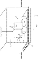
- Fig. 1 is a schematic block diagram illustrating a coating system 10 for coating a surface of a product built and operative according to some embodiments of the present invention.
- the product to be coated may be a rigid product, for example, a board or a panel and system 100 may coat at least one surface of the board or the panel.
- System 10 may comprise a coating unit 30, a curing unit 60 and a control unit 70.
- System 100 may further include a conveyor 200 which may be adapted to convey products to be coated into, through and out of system 10.
- System 10 may further comprise additional units as may be desired and/or required, depending on the substrate, on the coating system and method, etc.
- system 10 may further comprise pre-coating surface preparation unit 20 may be located before coating unit 30 along the production line.
- Substrate may enter system 10 via unit 20 and be treated so as to improve the performance of coating unit 30.
- unit 20 may include any device performing any method that improves the surface tension.
- anti-static means may be used that may be achieved by corona radiation. These treatments may be applied onto the substrate and thus raise its temperature and as a result - it may strengthen the surface tension and the attraction of the coating material to the substrate.
- pre-coating surface preparation unit 20 may be completely eliminated or may be designed and or tuned to provide the desired pre-coating treatment, as derived from the nature of the substrate, the coating material and the desired results of the coating.
- Control unit 70 may perform all of the control tasks of the other units of system 10. Accordingly, control unit 70 may receive data indicative of the progress of the coating process in each unit, data indicative of the ambient conditions in various units, such as temperature, humidity, speed of progress, amount of radiation energy, distance of the deposition head form the substrate, etc.
- Control unit 70 may comprise a controller, a CPU or any similar controlling unit, and a non-transitory data storage unit, such as RAM, ROM, hard disk and the like. Control commands and programs may be stored on the non-transitory data storage which when executed may cause system 10 to carry out the operations described in this application.
- Conveyor may pass through unit 20 in order to advance the product through unit 20 and to further provide it to coating unit 30.
- Conveyor 20 may convey products to coating system 10 from the production line.
- coating system 10 may be adopted to be included in the product production line.
- the production line may have a production rate and coating system 10 may be adopted to coat the surface of the product at the production rate.
- Coating unit 30 may receive product (e.g., substrate) 100, for example by means of conveyor 200, directly from a production line (not shown) or from storage area and the substrate may or may not be pre-treated in pre-coating surface preparation unit 20, as may be desired.
- Coating unit 30 may comprise one or more droplet deposition assembly 32, such as ink-jet printing head known in the printing industry. Droplet deposition assembly 32 may be configured to deposit droplets of a coating material from a plurality of nozzles according to a predetermined deposition pattern, to form a coating on the surface of product 100.
- Droplet deposition assembly 32 may comprise droplet deposition head 32B, operatively connected to droplet head movement unit 32A.
- Droplet deposition head 32B may comprise a plurality of droplet deposition nozzles, formed in any desired line or array, typically aimed to deposit droplets onto the surface of the substrate 100 in deposition direction which is substantially perpendicular to the surface of the product, yet other deposition directions may be used, as may be required.
- Droplet deposition head 32B may be movable by droplet head movement unit 32A relative to substrate 100 along one or more reference frame axes, such as Cartesian axes X, Y and Z as illustrated in Fig. 2 , wherein axis X is parallel to the direction of movement A of conveyor 200 (or the production direction through coating unit 30), axis Y is perpendicular to axis X and parallel to the plane of conveyor 200 (or parallel to the plane of substrate when it is a flat sheet), and axis Z is perpendicular to axes X and Y.
- reference frame axes such as Cartesian axes X, Y and Z as illustrated in Fig. 2 , wherein axis X is parallel to the direction of movement A of conveyor 200 (or the production direction through coating unit 30), axis Y is perpendicular to axis X and parallel to the plane of conveyor 200 (or parallel to the plane of substrate when it is a flat sheet), and axis Z is perpendic
- Droplet deposition head 32B may also be movable about an imaginary or real turning point 32C about one or more turning axes x , y , z in either direction, where turning axis x may be defined as perpendicular to plane Y-Z, turning axis y may be defined as perpendicular to plane X-Z, and turning axis z may be defined as perpendicular to plane X-Y.
- the degree of freedom may be selected according to the desired performance. For example, if only flat panels or sheets are to be coated, one or two Cartesian degrees of freedom may be required in order to provide full coverage of substrate 200, depending on the specific construction of deposition head 32B and the actual size of substrate 200 and another Cartesian degree of freedom may be required to enable control of the distance d from which droplets of coating material are deposited. When a 3D formed substrate (not shown) is to be coated, full 6-degrees of freedom may be required in order to provide coating in the required parameters, such as angle of deposition and distance d from the substrate surface.
- control unit 70 may control all or part of the coating parameters, related both to the movement of deposition head 32B (in any one of the N degrees of freedom, 1 ⁇ N ⁇ 6) and to the droplet deposition performance, such as droplet size, droplet temperature, droplet deposition speed, deposition distance, direction of deposition with respect to the direction of the surface being coated, etc.
- one of the deposition parameters may be the droplet deposition speed at the surface of substrate 100, and another deposition parameter may be the droplet size. Both parameters may have great influence on the homogeneity of the coating layer. The smaller the droplet and the higher the deposition speed of the droplet, the higher is the tendency of droplets to unite with each other at a thinner coating layer. As the size of the droplets decreases, the deposition resolution needs to become higher (e.g., higher dots per inch (DPI) figure), in order to deposit the droplets in the required distance from one another. Typical resolution of the droplets deposition may be 600 DPI; however, other, typically higher, resolutions may be used.
- DPI dots per inch
- control unit may control the deposition parameters such that the coating may have a thickness deviation of less than 1 micron per 1 meter.
- Deposition head 32B may comprise any required number of nozzles, arranged in 1- or 2-dimension array, as is known in the art. Since deposition head 32B may move along axis Y, perpendicular to the direction of movement of the product that needs to be coated, deposition head 32B may deposit coating layer onto as wide as desired surfaces, where the width of the surface and the number of nozzles in depositing head 32B will dictate the coating velocity of the product.
- a typical coating speed may be 1-5 meters/min.
- Typical droplet deposition speed may be 7-9 meter/second and this speed may enable deposition from virtually any direction with respect to direction of gravity, since the magnitude of the gravity force acting on a deposited droplet is negligible compared with the deposition speed energy.
- Typical size of droplets according to embodiments of the present invention may be less than 50 Pico-liter, which is smaller than 30 Nano-gram.
- a coating layer of less than 1 micron may be achieved and the coating's thickness deviation may be less than 1 micron per 1 meter.
- the distance between two consecutive nozzles may be smaller than 350 microns, which enables high accuracy of the location at which each droplet is placed on the surface.
- Use of such printing heads imposes that the viscosity of the coating material will be in the range of 2-30 centipoises. With some coating materials, this viscosity requires use of solvents and/or heating of the coating fluid.
- Some embodiments of the invention may be related to a method of coating a surface of a product, for example, a ridged product such as a panel or a board.
- the method may include depositing droplets of a coating material in a predetermined pattern on the surface from a plurality of nozzles included in a droplet deposition assembly; the coating material includes at least one polymeric component.
- a coating material that includes a urethane acrylate may be deposited using an inkjet print head having a plurality of nozzles.
- the predetermined pattern may include depositing a single coating material, while in other embodiments the method may include depositing two different types of coating materials and the predetermined pattern comprises the location of each droplet from the two different types of coating materials, as illustrated in Figs. 3-4 .
- the method may further include curing the at least one polymeric component in the deposited coating material to form a coating on the surface of product 100.
- a curing energy source such as a UV lamp
- the coating may have a thickness deviation of less than 1 micron per 1 meter.
- a polymeric coating for coating a surface of a rigid product may include a coating material having at least one polymeric component.
- the polymeric coating may be deposited on top of at least a portion of a surface of a ridged product, for example, a board or a panel.
- the coating may cover the surface of the product such that the thickness of the coating may have a thickness deviation of less than 1 micron per 1 meter, for example, less than 0.5 micron per meter.
- the polymeric coating, coated for example, by system 10 may be transparent in the visual light.
- such coating may be at least 70% transparent to visual light according to ASTM D1003, for example, 80% or 90% transparent.
- the polymeric coating may have a width of at least 3 meters.
- the width of the coating may be defined as the relative distance that droplet deposition assembly 32 travels in the Y direction (as illustrated in Fig. 2 ) from one side of object 100 (e.g. a board) to the other side, while depositing the coating material.
- assembly system may travel along the Y direction of object 100.
- object 100 may be movable in the Y direction with respect to assembly 32.
- assembly 32 may have the width of object 100 such that no relative movement is required between assembly 32 and object 100.
- Fig. 3 is a schematic illustration of a deposition patterns (e.g.. a coating scheme), according to some embodiments of the present invention.
- Substrate 100 may pass through a coating unit, such as coating unit 30, in one of three possible coating embodiments.
- the deposition head is moveable and is controlled similar to deposition head 32B of Figure 2 .
- the deposition head such as deposition head 332, is adapted to deposit one coating material from all of the nozzles (i.e., 332A and 332B are the same), such that the entire deposition pattern 150 includes an homogeneous deposition of a single coating material.
- deposition head 332 may deposit the coating material in order to get the needed characteristics after the (ultra violet) UV curing.
- a coating may have a thickness of at most 10 microns, for example, 1-8microns or 0.5-5 microns.
- droplet deposition assembly 32 may be configured to deposit more than one type of coating material.
- droplet deposition assembly 32 may be configured to deposit two types of coating materials and the predetermined pattern may include predetermined locations 150A and 150B for depositing droplets of each of the two types of coating materials.
- each of the different coating materials may include polymeric component and curing (e.g., by curing unit 60) may include curing the polymeric component at each of the two different coating materials such that a cross-related matrix is formed having a desired feature of the two coating materials
- the two different coating materials may be deposited, from two different sets of nozzles (332A and 332B).
- deposition head 332 may deposit a first coating material according to a first deposition scheme, schematically represented by scheme 150A, to create a first matrix of coating and deposit a second coating material according to a second deposition scheme 150B, to create a second matrix of coating.
- first and second coating materials are placed, or registered, substantially on top of each other shifted with respect to each-other (registered) as schematically represented by scheme 150
- the second coating material may react with, or cross-link with, or mechanically relate to the first material thus creating a combined coating material presenting new features of the combination of the features of the first and the second coating materials for example with enhanced bonding to the surface of product 100.
- the first coating material may be acrylic resin which provides abrasion, scratch, chemical and UV resistance.
- the second coating material may be a silver/mercury compound, which provides anti-bacterial property.
- deposition head 332 is also adapted to deposit two different coating materials from two different sets of nozzles like method no. 2.
- the droplets will be deposited next to each other in order to provide a porous surface which may provide mechanical protection for material 410A that includes solution with solid functional particles by material 410B that includes a polymeric component, such that the predetermined pattern comprises functional particles of the material 410A interlaced in a grid of the material 410B.
- nanoparticles of silica filaments may find mechanical protection between droplets of acrylic resins as schematically described in Fig.
- FIG. 4 which is a schematic illustration of interlaced deposition schemes 410A and 410B, according to embodiments of the present invention, in which high dots of urethane acrylate (graphically represented by the symbol ⁇ ) are interlaced with dots of silica between (graphically represented by the symbol ), to achieve anti-scratch and hydrophobic coating layer with improved resistance to physical removal of the silica dots due to the physical protection by the urethane acrylate grid:
- the deposition of two materials may lead to polymerization (by curing) of the two materials directly on the coated surface which, according to some embodiments of the invention, may result a coating layer having the desired features of the two materials.
- a coating having two coating materials deposited on the substrate at the predetermined pattern e.g., patterns 150, 150A, 150B, 410A, and 410B
- cross-related matrices 150A and 150B, creating a combined matrices coating 150 may be achieved using deposition heads other than 332.
- deposition heads other than 332.
- two different deposition heads the first depositing the first coating material and the second depositing the second coating material, while a control unit, such as control unit 70, governs the exact location of each of the coating material droplets in a matrices.
- only single deposition head may be used, in two consecutive passes, where the deposition of the second coating material may be carried out after the deposition of the first coating material. This embodiment may lower the cost of the deposition unit on the expense of lower coating capacity, and the first and second coating materials will have to be selected properly so that the time gap between the deposition of the first and of the second materials will not harm the required final result.
- the second coating material may be deposited onto the first coating material (first and second coating schemes are substantially overlapping), thus enabling polymerization of the first and the second materials directly on substrate 100.
- the coating may include a repetitive deposition pattern, of first and second coating materials (e.g., patterns, 150A, 150B, 410A and 410B).
- Such repetitive pattern may have a constant distance between and two neighboring particles, of the same coating material and/or another coating material in at least one of a row and a column of the pattern. In some embodiments, the distance may be at most 70 microns.
- the method may further include heating the surface of the product prior to depositing the coating material, for example, by using surface preparation unit 20.
- the method may include, evaporation the solvents remaining at the outlet of coating unit 30 in solvent evaporation unit 40, tor example by means of heating, forced venting and spontaneous evaporation by time. It will be appreciated by those skilled in the art that evaporation of residual solvents may be done spontaneously, or may not be required at all, depending, among other, on the initial amount of solvents in the coating material, the evaporation tendency of the solvent, the production speed and the ambient conditions.
- the method may include heating the coated material after the deposition.
- Substrate 100 may pass through heating unit 50 in which the coating is heated to a temperature range depending on the previous process temperature. If the deposition relied on coating with solvents, the heating will be applied to lower the viscosity of the coating material to allow residual solvents to evaporate and to improve wetting of the substrate by the coating material, or optional range of temperature-30-120 °C depending on the solvent selection and the resin type in order to assist residual solvent trapped between the coating layer and the surface of substrate 100 to evaporate.
- the heating may also assist in flattening the coating layer by heating the coating material the viscosity figure of which is now higher, due to the evaporation of the solvent, such that the coating thickness deviation is a low as possible, for example, less than 1 micron per 1 meter, or even less than 0.5 micron per 1 meter.
- the length of exposure of substrate 100 to heat in heating unit 50, and the temperature of heating may be decided according to the selected coating material, the initial capacity of solvents, the production speed, the ambient conditions and the like. All of these parameters may be controlled by control unit 70 as to cause the coating thickness deviation to be of less than 1 micron per 1 meter.
- Curing unit 60 may include curing by ultraviolet radiation or any other curing device known in the art.
- the coated product may be transferred to curing unit 60 directly after coating unit 30. Additionally, the coated product may be heated by heating unit 40 prior to entering curing unit 60.
- a preferred range of temperature for liquid coating materials with viscosity range below 100 Centipoise was 30-60°C, and a further preferred temperature of the coating materials in the printing head before depositing may be 80°C.
- the method may further include controlling the droplets size to be in a preferred range of droplet size for example, the droplets may be smaller than 50 Pico liter.
- the preferred range for a coating material type urethane acrylate may be 10-35 Pico liter.
- the velocity of a droplet of coating material, measured at the outlet from the printing head has also influence of the quality of the coating.
- the method may include controlling a velocity of the droplets to be less than 20 meter/second. For example, it was found that for a coating material type urethane acrylate deposition, velocity of droplets in the range of 7-9 meter/second proved good wetting results (i.e., homogeneity and thinner layer) and good visual results (i.e., the coating seems to the eye clean and clear). It will be noted that too low depositing velocity may cause too small spreading of the droplet on the surface, and too high depositing velocity may cause particles of the droplet to bounce back from the surface and tear off the droplet causing uneven coating at that location. In general, the kinetic energy given to the droplet due to the deposition velocity should balance with the surface tension force of the droplet, so that maximum spreading of the droplet is achieved without causing the droplet to break or to bounce back from the surface.
- the optimal distance of the deposition head from the surface was tested.
- the distance between a face of droplet deposition assembly 36 facing the surface and the surface 100 is between 0.5-10 mm.
- deposition distance of 1-3 mm proves good coating features when the deposition velocity is in the preferred range defined above. Deposition in this velocity range and distance range ensures good spreading of the droplet, and, together with the fact that the spreading remains in a specific confined area on the surface, it is also ensured that the required deposition resolution is maintained.
- deposition direction from the deposition head to the coated surface may be done in virtually any direction with respect to the gravity direction.
- the differences between extremum such as deposition with the direction of gravity and opposite the direction of gravity may be compensated by, for example, increasing the deposition velocity when depositing in a direction opposite to the direction of gravity, compared to the deposition velocity when depositing parallel to the direction of gravity.
- the thickness of the coating layer may be controlled and may be lowered to less than 10 microns (depending on the coating material).
- the deposition parameters through which the deposition thickness may be controlled may be the voltage of the deposition (which controls the deposition velocity) and frequency of deposition (which controls the number of droplets per certain defined coated area), and it is possible to control the degree of cross-linking (DC) of two materials that are deposited on each-other.
- DC degree of cross-linking
- deposition and coating parameters that take part in the process may be coating speed of the substrate of 1 m/minute, spontaneous evaporation of the solvent in room temperature for 2 minutes and then exposure to heating gradient from 60°C to 90°C in 2 minutes by a mercury lamp of the type H+.
- the degree of cross-linking of the coating materials in the different depths of the coating layer may be controlled through control of the temperature the materials is exposed to and/or the time of exposure. Too fast cross linking at the surface of the coating layer may be delayed by the undesired reaction of the materials with oxygen in the air instead of cross-linking.
- Cross-linking in depth relatively far from the surface of the coating may be delayed, or maintain low degree of cross-linking, stage due to poorer penetration of the lamp's excitation/curing energy.
- Fig. 5 depicting the effect of the depth of the coating layer on the level of cross-linking according to embodiments of the present invention. It may be seen that the highest degree of cross-linking (percentage) is achieved, in the example, of Fig. 5 , at depth of about 18 microns with cross-linking degree of approx. 80%, while closer to the surface (at 15 microns) the degree of cross-linking is lower (approx. 70%) and at higher depths, e.g. in depth of 30 microns, the degree of cross-linking is approx. 68%.
- the abrasion resistance as the outcome of the degree of cross-linking, after the end of curing stage, may be measured by the Taber ASTM D1044 standard for testing level of grinding.
- the results after 100 grinding revolutions showed degradation of less than 4% in the visual light transparency of the coating layer and after 500 revolutions degradation of less than 8% of visual light transparency.
- the degree of viscosity of the coating material, at the time of deposition, has effect on the quality of the final coating.
- lower viscosity requires, with many of the usable coating materials, longer time of solvent evaporation, higher pre-heating and higher amount of evaporation energy.
- the inventor of the present invention has discovered that, with coating material of urethane acrylate, viscosity in the range of 2-30 centipoise (cP) brings high quality of the coating layer.
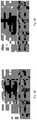
- Figs. 6A - 6F depict the dependency of the thickness of a flattening droplet, on the size (or volume) of the droplet.
- Figs. 6A-6C depict three stages of flattening of a 5ml droplet
- Figs. 6D - 6F depict three stages of flattening of a 25ml droplet.
- a droplet is presented laying on a polycarbonate (PC) surface.
- the initial thickness of the droplet is 4021.162 ⁇ m.
- the droplet's thickness is 2474 ⁇ m
- Fig. 6C the virtually final thickness of the droplet is 618.
- the initial thickness of the droplet is 6805 ⁇ m.
- the droplet further flattens to reach thickness of 5103 ⁇ m, and in Fig. 6F , the droplet of 25 ml reaches a virtually final thickness of 1391 ⁇ m, which is more than twice the final thickness of the 5ml droplet.
- the achievable resolution of deposition was also examined, in the range of 500 - 3000 dots per inch (DPI). Assuming a relatively fixed size/volume of a deposited droplet, it was found that the higher the thickness of the coating layer is, the higher is the achievable resolution, since droplets may be deposited in multiple deposition sub-layers and, therefore, may be located in higher density per given substrate area. It was discovered that, for the conditions comprising temperature of 40°C in the preheat stage before the application stage, a stay of 2 minutes in a room temperature at the evaporation tunnel and exposure to 60-90°C at the heating tunnel, deposition at resolution of 1100 DPI provides optimal result for homogeneous coating layer.
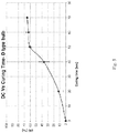
- Fig. 7 is a graph showing the dependency of tendency of the coating layer to peel off the substrate (measured in the number of hours of exposure to UV radiation before the coating layer begins to peel off) subject of the heating temperature in the heating section. It is seen clearly that the higher the heating temperature is, the better is the attachment of the coating layer (the lower is the tendency to peel off).
- the final heating temperature is 40°C
- the coating material will begin to peel off after 1000 hours of exposure to ambient conditions, and when it is heated to final temperature of 90°C, it will hold for 3000 hours in ambient conditions before peeling off.
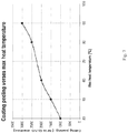
- Fig. 8 depicts the effect of the time of travel of a coated substrate in the drying/evaporation unit, for 5 different speeds of the conveyor (0.5, 1, 2, 3 and 5 m/min) for two different number of abrasion cycles (100 and 500 cycles).
- the resistance to abrasion is presented by grade of haziness of the substrate. It is clearly seen that the longer the substrate stays in the drying/evaporation unit, the lower is the haziness grade (showing better resistance to abrasion).
- the explanation may be that the longer the coating stays in the drying/evaporation unit, the higher is the percentage of evaporation of the solvents and the higher is degree of crosslinking.
- the quality of coating according to some embodiments of the present invention depends, inter alia, on the wetting factor of the coating material with respect to the substrate being coated.
- the surface tension number of PC is 38 mN/m
- the surface tension factor of a coating material used by the inventor in tests is 33 mN/m, which complies with the requirement that the coating material should have surface tension factor lower than that of the substrate it is coating.
- the surface tension of the substrate may be made even higher by raising its temperature, which in turn will improve the wetting of the coating layer.
- the use of a deposition head (one or more) for depositing two materials that should react to create high degree of cross-linking with a deposition scheme that deposits one of the materials onto the other material, with droplets as small as 10-15 Pico liter in volume, and deposition of the second material offset with respect to the deposition location of the first material the intense contact of the two materials with each other may encourage higher degree of cross-linking even with less use of heating or curing by radiation, due to intense reaction between the droplets of the two materials, and especially when the two materials tend to dissolve with each other.
Landscapes
- Chemical & Material Sciences (AREA)
- Life Sciences & Earth Sciences (AREA)
- Engineering & Computer Science (AREA)
- Materials Engineering (AREA)
- Wood Science & Technology (AREA)
- Organic Chemistry (AREA)
- Application Of Or Painting With Fluid Materials (AREA)
Claims (5)
- Verfahren zum Beschichten einer Oberfläche eines Produkts (100), umfassend:Abscheiden von Tröpfchen eines Beschichtungsmaterials in einem vorbestimmten Muster (150) auf der Oberfläche aus einer Vielzahl von Düsen (32A, 32B), die in einer Tröpfchenabscheidungsanordnung (32) enthalten sind, wobei das Beschichtungsmaterial mindestens eine polymere Komponente enthält;Erhitzen der Oberfläche des Produkts (100) nach dem Abscheiden der Tröpfchen, um einen vorbestimmten Temperaturgradienten entlang des Produkts in einer Produktionsrichtung zu bewirken; undAushärten der mindestens einen polymeren Komponente im abgeschiedenen Beschichtungsmaterial, um eine Beschichtung auf der Oberfläche zu bilden,wobei das Abscheiden ein Abscheiden von zwei verschiedenen Arten von Beschichtungsmaterialien umfasst und das vorbestimmte Muster (150) den Ort jedes Tröpfchens aus den zwei verschiedenen Arten von Beschichtungsmaterialien umfasst, undwobei ein erstes Beschichtungsmaterial (410B) eine polymere Komponente enthält und das zweite Beschichtungsmaterial (410A) eine Lösung mit festen funktionellen Teilchen umfasst, so dass das vorbestimmte Muster (150) funktionelle Teilchen des zweiten Materials umfasst, die in einem Gitter des ersten Materials verflochten sind.
- Verfahren nach Anspruch 1, umfassend ein Erhitzen des beschichteten Materials nach der Abscheidung, um die Beschichtung dergestalt abzuflachen, dass sie eine Dickenabweichung von weniger als 1 Mikrometer pro 1 Meter aufweist.
- Verfahren nach Anspruch 1, wobei jedes der verschiedenen Beschichtungsmaterialien eine polymere Komponente umfasst und wobei das Aushärten ein Aushärten der polymeren Komponente an jedem der zwei verschiedenen Beschichtungsmaterialien beinhaltet, sodass eine übergreifend vernetzte Matrix gebildet wird, die ein gewünschtes Merkmal der zwei Beschichtungsmaterialien aufweist.
- Verfahren nach Anspruch 1, wobei das Abscheidungsmuster ein sich wiederholendes Muster ist, derart dass ein konstanter Abstand jeweils zwischen zwei benachbarten Teilchen in mindestens einer von einer Reihe und einer Spalte des Musters gebildet wird, sodass der Abstand höchstens 70 Mikrometer beträgt.
- Verfahren nach einem der Ansprüche 1-4,
wobei der vorbestimmte Temperaturgradient von 60 °C bis 90 °C verläuft.
Applications Claiming Priority (2)
| Application Number | Priority Date | Filing Date | Title |
|---|---|---|---|
| US201361910041P | 2013-11-28 | 2013-11-28 | |
| PCT/IL2014/051036 WO2015079447A1 (en) | 2013-11-28 | 2014-11-27 | System and method for applying thin coating on large area surface |
Publications (3)
| Publication Number | Publication Date |
|---|---|
| EP3077121A1 EP3077121A1 (de) | 2016-10-12 |
| EP3077121A4 EP3077121A4 (de) | 2017-09-20 |
| EP3077121B1 true EP3077121B1 (de) | 2018-11-14 |
Family
ID=53198460
Family Applications (1)
| Application Number | Title | Priority Date | Filing Date |
|---|---|---|---|
| EP14865277.9A Not-in-force EP3077121B1 (de) | 2013-11-28 | 2014-11-27 | Verfahren zum aufbringen einer dünnen beschichtung auf eine grossflächige oberfläche |
Country Status (6)
| Country | Link |
|---|---|
| US (1) | US10232638B2 (de) |
| EP (1) | EP3077121B1 (de) |
| CN (1) | CN105934280A (de) |
| AU (1) | AU2014356016A1 (de) |
| ES (1) | ES2706375T3 (de) |
| WO (1) | WO2015079447A1 (de) |
Families Citing this family (3)
| Publication number | Priority date | Publication date | Assignee | Title |
|---|---|---|---|---|
| DE112018006159T5 (de) * | 2017-11-30 | 2020-09-10 | Axalta Coating Systems Gmbh | Anstrichmittel zum auftragen unter verwendung eines applikators mit hohem auftragswirkungsgrad und verfahren und systeme dafür |
| US11020987B2 (en) * | 2019-04-08 | 2021-06-01 | LSINC Corporation | Method for ink pressure modulation in a printer for axially symmetric objects |
| WO2022106800A1 (en) * | 2020-11-19 | 2022-05-27 | Formology Holdings Limited | Antimicrobial coating system |
Family Cites Families (14)
| Publication number | Priority date | Publication date | Assignee | Title |
|---|---|---|---|---|
| US5266349A (en) | 1991-02-25 | 1993-11-30 | Specialty Coating Systems Inc. | Method of discrete conformal coating |
| JP2000153182A (ja) * | 1998-11-20 | 2000-06-06 | Nippon Paint Co Ltd | スプレー塗装機 |
| US6523921B2 (en) * | 2000-08-30 | 2003-02-25 | L&P Property Management | Method and apparatus for printing on rigid panels and other contoured or textured surfaces |
| US7669547B2 (en) * | 2001-03-14 | 2010-03-02 | 3M Innovative Properties Company | Coating apparatus |
| US6926772B2 (en) | 2002-02-27 | 2005-08-09 | 3M Innovative Properties Company | Strand coating device and method |
| DE10224128A1 (de) * | 2002-05-29 | 2003-12-18 | Schmid Rhyner Ag Adliswil | Verfahren zum Auftrag von Beschichtungen auf Oberflächen |
| US20070279182A1 (en) * | 2006-05-31 | 2007-12-06 | Cabot Corporation | Printed resistors and processes for forming same |
| KR101428718B1 (ko) * | 2007-02-02 | 2014-09-24 | 삼성디스플레이 주식회사 | 감광성 유기물, 이의 도포 방법, 이를 이용한 유기막 패턴형성 방법, 이로써 제조되는 표시 장치 |
| DE102007034877A1 (de) * | 2007-07-24 | 2009-01-29 | Schmid Rhyner Ag | Verfahren und Vorrichtung zum Auftrag von Kunststoffbeschichtungen |
| JP5062002B2 (ja) * | 2008-03-31 | 2012-10-31 | 住友化学株式会社 | 塗工方法および塗工装置 |
| US8383189B2 (en) * | 2008-04-21 | 2013-02-26 | Xerox Corporation | Selectable gloss coating system |
| US20120120142A1 (en) * | 2009-07-22 | 2012-05-17 | Tom Howard S | Inkjet printing system |
| US8531743B2 (en) * | 2010-10-18 | 2013-09-10 | Xerox Corporation | System and method for detecting missing inkjets in an inkjet printer using image data of printed documents without a priori knowledge of the documents |
| US9095865B2 (en) * | 2011-11-16 | 2015-08-04 | Csl Silicones Inc. | Mobile coating system for elastomeric materials |
-
2014
- 2014-11-27 US US15/039,034 patent/US10232638B2/en not_active Expired - Fee Related
- 2014-11-27 AU AU2014356016A patent/AU2014356016A1/en not_active Abandoned
- 2014-11-27 WO PCT/IL2014/051036 patent/WO2015079447A1/en active Application Filing
- 2014-11-27 CN CN201480074288.5A patent/CN105934280A/zh active Pending
- 2014-11-27 EP EP14865277.9A patent/EP3077121B1/de not_active Not-in-force
- 2014-11-27 ES ES14865277T patent/ES2706375T3/es active Active
Non-Patent Citations (1)
| Title |
|---|
| None * |
Also Published As
| Publication number | Publication date |
|---|---|
| EP3077121A4 (de) | 2017-09-20 |
| AU2014356016A1 (en) | 2016-06-23 |
| US20170209877A1 (en) | 2017-07-27 |
| EP3077121A1 (de) | 2016-10-12 |
| ES2706375T3 (es) | 2019-03-28 |
| CN105934280A (zh) | 2016-09-07 |
| WO2015079447A1 (en) | 2015-06-04 |
| US10232638B2 (en) | 2019-03-19 |
Similar Documents
| Publication | Publication Date | Title |
|---|---|---|
| RU2635965C2 (ru) | Способ и устройство для декорирования панели | |
| JP6399736B2 (ja) | 対象物の表面を画像形成及び/又は塗装する方法 | |
| US8561571B2 (en) | Apparatus and method of applying a coating solution | |
| EP1743707B1 (de) | Verfahren zum Auftragen von Beschichtungen auf Oberflächen | |
| US11097978B2 (en) | Bent substrate provided with print layer, and method for manufacturing same | |
| US20180186143A1 (en) | Apparatus for applying protective films | |
| EP3077121B1 (de) | Verfahren zum aufbringen einer dünnen beschichtung auf eine grossflächige oberfläche | |
| US20090169719A1 (en) | Method for printing high quality images on curved substrates | |
| TWI606021B (zh) | 玻璃邊緣塗佈之方法 | |
| CN108348955A (zh) | 用于尤其在可uv固化层中产生表面效果的方法、用于其制造的装置以及根据本发明获得的物品 | |
| JPH09201566A (ja) | 支持体に導電性塗膜を形成する方法 | |
| US10315405B2 (en) | Methods and apparatus for applying protective films | |
| EP1854549B1 (de) | Vorrichtung und Verfahren zur Beschichtung einer optischen Linse | |
| KR101511609B1 (ko) | 코팅 장치 | |
| KR20170140567A (ko) | 코팅장치 | |
| EP3362192B1 (de) | Vorrichtung und verfahren für schichtweise beschichtung | |
| WO2006057484A1 (en) | Apparatus for coating 2-d or 3-d extrusion materials with paint and coating method using the same | |
| KR102663505B1 (ko) | 잉크젯 프린트 시스템과 이를 이용한 잉크젯 프린팅 방법 | |
| US11945209B2 (en) | Methods and devices for printing on substrates | |
| WO2023122565A1 (en) | Methods of coating a substrate | |
| JP4982836B2 (ja) | ラミネート装置 | |
| CN114126771A (zh) | 形成图案化涂层的涂覆方法和系统 | |
| US20110091699A1 (en) | Method for manufacturing a laminate and product obtained | |
| JPH04243571A (ja) | 連続塗布方法およびその装置 |
Legal Events
| Date | Code | Title | Description |
|---|---|---|---|
| PUAI | Public reference made under article 153(3) epc to a published international application that has entered the european phase |
Free format text: ORIGINAL CODE: 0009012 |
|
| 17P | Request for examination filed |
Effective date: 20160627 |
|
| AK | Designated contracting states |
Kind code of ref document: A1 Designated state(s): AL AT BE BG CH CY CZ DE DK EE ES FI FR GB GR HR HU IE IS IT LI LT LU LV MC MK MT NL NO PL PT RO RS SE SI SK SM TR |
|
| AX | Request for extension of the european patent |
Extension state: BA ME |
|
| DAX | Request for extension of the european patent (deleted) | ||
| A4 | Supplementary search report drawn up and despatched |
Effective date: 20170818 |
|
| RIC1 | Information provided on ipc code assigned before grant |
Ipc: B05B 13/04 20060101ALN20170811BHEP Ipc: C09D 175/04 20060101AFI20170811BHEP Ipc: B05B 1/14 20060101ALN20170811BHEP |
|
| REG | Reference to a national code |
Ref country code: DE Ref legal event code: R079 Ref document number: 602014036240 Country of ref document: DE Free format text: PREVIOUS MAIN CLASS: B05B0001140000 Ipc: C09D0175040000 |
|
| GRAP | Despatch of communication of intention to grant a patent |
Free format text: ORIGINAL CODE: EPIDOSNIGR1 |
|
| RIC1 | Information provided on ipc code assigned before grant |
Ipc: B05D 3/02 20060101ALI20180426BHEP Ipc: C09D 175/04 20060101AFI20180426BHEP Ipc: B05D 1/34 20060101ALI20180426BHEP Ipc: B05D 5/00 20060101ALN20180426BHEP Ipc: B05B 1/14 20060101ALN20180426BHEP Ipc: B05D 1/28 20060101ALI20180426BHEP Ipc: B05B 13/04 20060101ALN20180426BHEP |
|
| RIC1 | Information provided on ipc code assigned before grant |
Ipc: B05D 1/34 20060101ALI20180427BHEP Ipc: B05D 3/02 20060101ALI20180427BHEP Ipc: C09D 175/04 20060101AFI20180427BHEP Ipc: B05D 5/00 20060101ALN20180427BHEP Ipc: B05D 1/28 20060101ALI20180427BHEP Ipc: B05B 1/14 20060101ALN20180427BHEP Ipc: B05B 13/04 20060101ALN20180427BHEP |
|
| INTG | Intention to grant announced |
Effective date: 20180523 |
|
| GRAS | Grant fee paid |
Free format text: ORIGINAL CODE: EPIDOSNIGR3 |
|
| GRAA | (expected) grant |
Free format text: ORIGINAL CODE: 0009210 |
|
| AK | Designated contracting states |
Kind code of ref document: B1 Designated state(s): AL AT BE BG CH CY CZ DE DK EE ES FI FR GB GR HR HU IE IS IT LI LT LU LV MC MK MT NL NO PL PT RO RS SE SI SK SM TR |
|
| REG | Reference to a national code |
Ref country code: CH Ref legal event code: EP Ref country code: AT Ref legal event code: REF Ref document number: 1064778 Country of ref document: AT Kind code of ref document: T Effective date: 20181115 |
|
| REG | Reference to a national code |
Ref country code: DE Ref legal event code: R096 Ref document number: 602014036240 Country of ref document: DE |
|
| REG | Reference to a national code |
Ref country code: IE Ref legal event code: FG4D |
|
| REG | Reference to a national code |
Ref country code: NL Ref legal event code: MP Effective date: 20181114 |
|
| REG | Reference to a national code |
Ref country code: LT Ref legal event code: MG4D |
|
| REG | Reference to a national code |
Ref country code: ES Ref legal event code: FG2A Ref document number: 2706375 Country of ref document: ES Kind code of ref document: T3 Effective date: 20190328 |
|
| REG | Reference to a national code |
Ref country code: AT Ref legal event code: MK05 Ref document number: 1064778 Country of ref document: AT Kind code of ref document: T Effective date: 20181114 |
|
| PG25 | Lapsed in a contracting state [announced via postgrant information from national office to epo] |
Ref country code: FI Free format text: LAPSE BECAUSE OF FAILURE TO SUBMIT A TRANSLATION OF THE DESCRIPTION OR TO PAY THE FEE WITHIN THE PRESCRIBED TIME-LIMIT Effective date: 20181114 Ref country code: HR Free format text: LAPSE BECAUSE OF FAILURE TO SUBMIT A TRANSLATION OF THE DESCRIPTION OR TO PAY THE FEE WITHIN THE PRESCRIBED TIME-LIMIT Effective date: 20181114 Ref country code: AT Free format text: LAPSE BECAUSE OF FAILURE TO SUBMIT A TRANSLATION OF THE DESCRIPTION OR TO PAY THE FEE WITHIN THE PRESCRIBED TIME-LIMIT Effective date: 20181114 Ref country code: LV Free format text: LAPSE BECAUSE OF FAILURE TO SUBMIT A TRANSLATION OF THE DESCRIPTION OR TO PAY THE FEE WITHIN THE PRESCRIBED TIME-LIMIT Effective date: 20181114 Ref country code: NO Free format text: LAPSE BECAUSE OF FAILURE TO SUBMIT A TRANSLATION OF THE DESCRIPTION OR TO PAY THE FEE WITHIN THE PRESCRIBED TIME-LIMIT Effective date: 20190214 Ref country code: IS Free format text: LAPSE BECAUSE OF FAILURE TO SUBMIT A TRANSLATION OF THE DESCRIPTION OR TO PAY THE FEE WITHIN THE PRESCRIBED TIME-LIMIT Effective date: 20190314 Ref country code: BG Free format text: LAPSE BECAUSE OF FAILURE TO SUBMIT A TRANSLATION OF THE DESCRIPTION OR TO PAY THE FEE WITHIN THE PRESCRIBED TIME-LIMIT Effective date: 20190214 Ref country code: LT Free format text: LAPSE BECAUSE OF FAILURE TO SUBMIT A TRANSLATION OF THE DESCRIPTION OR TO PAY THE FEE WITHIN THE PRESCRIBED TIME-LIMIT Effective date: 20181114 |
|
| PG25 | Lapsed in a contracting state [announced via postgrant information from national office to epo] |
Ref country code: AL Free format text: LAPSE BECAUSE OF FAILURE TO SUBMIT A TRANSLATION OF THE DESCRIPTION OR TO PAY THE FEE WITHIN THE PRESCRIBED TIME-LIMIT Effective date: 20181114 Ref country code: PT Free format text: LAPSE BECAUSE OF FAILURE TO SUBMIT A TRANSLATION OF THE DESCRIPTION OR TO PAY THE FEE WITHIN THE PRESCRIBED TIME-LIMIT Effective date: 20190314 Ref country code: NL Free format text: LAPSE BECAUSE OF FAILURE TO SUBMIT A TRANSLATION OF THE DESCRIPTION OR TO PAY THE FEE WITHIN THE PRESCRIBED TIME-LIMIT Effective date: 20181114 Ref country code: GR Free format text: LAPSE BECAUSE OF FAILURE TO SUBMIT A TRANSLATION OF THE DESCRIPTION OR TO PAY THE FEE WITHIN THE PRESCRIBED TIME-LIMIT Effective date: 20190215 Ref country code: RS Free format text: LAPSE BECAUSE OF FAILURE TO SUBMIT A TRANSLATION OF THE DESCRIPTION OR TO PAY THE FEE WITHIN THE PRESCRIBED TIME-LIMIT Effective date: 20181114 Ref country code: SE Free format text: LAPSE BECAUSE OF FAILURE TO SUBMIT A TRANSLATION OF THE DESCRIPTION OR TO PAY THE FEE WITHIN THE PRESCRIBED TIME-LIMIT Effective date: 20181114 |
|
| REG | Reference to a national code |
Ref country code: CH Ref legal event code: PL |
|
| PG25 | Lapsed in a contracting state [announced via postgrant information from national office to epo] |
Ref country code: CZ Free format text: LAPSE BECAUSE OF FAILURE TO SUBMIT A TRANSLATION OF THE DESCRIPTION OR TO PAY THE FEE WITHIN THE PRESCRIBED TIME-LIMIT Effective date: 20181114 Ref country code: LU Free format text: LAPSE BECAUSE OF NON-PAYMENT OF DUE FEES Effective date: 20181127 Ref country code: PL Free format text: LAPSE BECAUSE OF FAILURE TO SUBMIT A TRANSLATION OF THE DESCRIPTION OR TO PAY THE FEE WITHIN THE PRESCRIBED TIME-LIMIT Effective date: 20181114 Ref country code: IT Free format text: LAPSE BECAUSE OF FAILURE TO SUBMIT A TRANSLATION OF THE DESCRIPTION OR TO PAY THE FEE WITHIN THE PRESCRIBED TIME-LIMIT Effective date: 20181114 Ref country code: DK Free format text: LAPSE BECAUSE OF FAILURE TO SUBMIT A TRANSLATION OF THE DESCRIPTION OR TO PAY THE FEE WITHIN THE PRESCRIBED TIME-LIMIT Effective date: 20181114 |
|
| REG | Reference to a national code |
Ref country code: DE Ref legal event code: R097 Ref document number: 602014036240 Country of ref document: DE |
|
| REG | Reference to a national code |
Ref country code: BE Ref legal event code: MM Effective date: 20181130 |
|
| REG | Reference to a national code |
Ref country code: IE Ref legal event code: MM4A |
|
| PG25 | Lapsed in a contracting state [announced via postgrant information from national office to epo] |
Ref country code: SM Free format text: LAPSE BECAUSE OF FAILURE TO SUBMIT A TRANSLATION OF THE DESCRIPTION OR TO PAY THE FEE WITHIN THE PRESCRIBED TIME-LIMIT Effective date: 20181114 Ref country code: EE Free format text: LAPSE BECAUSE OF FAILURE TO SUBMIT A TRANSLATION OF THE DESCRIPTION OR TO PAY THE FEE WITHIN THE PRESCRIBED TIME-LIMIT Effective date: 20181114 Ref country code: SK Free format text: LAPSE BECAUSE OF FAILURE TO SUBMIT A TRANSLATION OF THE DESCRIPTION OR TO PAY THE FEE WITHIN THE PRESCRIBED TIME-LIMIT Effective date: 20181114 Ref country code: MC Free format text: LAPSE BECAUSE OF FAILURE TO SUBMIT A TRANSLATION OF THE DESCRIPTION OR TO PAY THE FEE WITHIN THE PRESCRIBED TIME-LIMIT Effective date: 20181114 Ref country code: RO Free format text: LAPSE BECAUSE OF FAILURE TO SUBMIT A TRANSLATION OF THE DESCRIPTION OR TO PAY THE FEE WITHIN THE PRESCRIBED TIME-LIMIT Effective date: 20181114 Ref country code: CH Free format text: LAPSE BECAUSE OF NON-PAYMENT OF DUE FEES Effective date: 20181130 Ref country code: LI Free format text: LAPSE BECAUSE OF NON-PAYMENT OF DUE FEES Effective date: 20181130 |
|
| PLBE | No opposition filed within time limit |
Free format text: ORIGINAL CODE: 0009261 |
|
| STAA | Information on the status of an ep patent application or granted ep patent |
Free format text: STATUS: NO OPPOSITION FILED WITHIN TIME LIMIT |
|
| 26N | No opposition filed |
Effective date: 20190815 |
|
| PG25 | Lapsed in a contracting state [announced via postgrant information from national office to epo] |
Ref country code: IE Free format text: LAPSE BECAUSE OF NON-PAYMENT OF DUE FEES Effective date: 20181127 Ref country code: SI Free format text: LAPSE BECAUSE OF FAILURE TO SUBMIT A TRANSLATION OF THE DESCRIPTION OR TO PAY THE FEE WITHIN THE PRESCRIBED TIME-LIMIT Effective date: 20181114 |
|
| PG25 | Lapsed in a contracting state [announced via postgrant information from national office to epo] |
Ref country code: BE Free format text: LAPSE BECAUSE OF NON-PAYMENT OF DUE FEES Effective date: 20181130 |
|
| PG25 | Lapsed in a contracting state [announced via postgrant information from national office to epo] |
Ref country code: MT Free format text: LAPSE BECAUSE OF NON-PAYMENT OF DUE FEES Effective date: 20181127 |
|
| PG25 | Lapsed in a contracting state [announced via postgrant information from national office to epo] |
Ref country code: TR Free format text: LAPSE BECAUSE OF FAILURE TO SUBMIT A TRANSLATION OF THE DESCRIPTION OR TO PAY THE FEE WITHIN THE PRESCRIBED TIME-LIMIT Effective date: 20181114 |
|
| PG25 | Lapsed in a contracting state [announced via postgrant information from national office to epo] |
Ref country code: HU Free format text: LAPSE BECAUSE OF FAILURE TO SUBMIT A TRANSLATION OF THE DESCRIPTION OR TO PAY THE FEE WITHIN THE PRESCRIBED TIME-LIMIT; INVALID AB INITIO Effective date: 20141127 Ref country code: MK Free format text: LAPSE BECAUSE OF NON-PAYMENT OF DUE FEES Effective date: 20181114 Ref country code: CY Free format text: LAPSE BECAUSE OF FAILURE TO SUBMIT A TRANSLATION OF THE DESCRIPTION OR TO PAY THE FEE WITHIN THE PRESCRIBED TIME-LIMIT Effective date: 20181114 |
|
| PGFP | Annual fee paid to national office [announced via postgrant information from national office to epo] |
Ref country code: FR Payment date: 20201117 Year of fee payment: 7 Ref country code: GB Payment date: 20201117 Year of fee payment: 7 Ref country code: ES Payment date: 20201216 Year of fee payment: 7 Ref country code: DE Payment date: 20201130 Year of fee payment: 7 |
|
| REG | Reference to a national code |
Ref country code: DE Ref legal event code: R119 Ref document number: 602014036240 Country of ref document: DE |
|
| GBPC | Gb: european patent ceased through non-payment of renewal fee |
Effective date: 20211127 |
|
| PG25 | Lapsed in a contracting state [announced via postgrant information from national office to epo] |
Ref country code: GB Free format text: LAPSE BECAUSE OF NON-PAYMENT OF DUE FEES Effective date: 20211127 Ref country code: DE Free format text: LAPSE BECAUSE OF NON-PAYMENT OF DUE FEES Effective date: 20220601 |
|
| PG25 | Lapsed in a contracting state [announced via postgrant information from national office to epo] |
Ref country code: FR Free format text: LAPSE BECAUSE OF NON-PAYMENT OF DUE FEES Effective date: 20211130 |
|
| REG | Reference to a national code |
Ref country code: ES Ref legal event code: FD2A Effective date: 20230222 |
|
| PG25 | Lapsed in a contracting state [announced via postgrant information from national office to epo] |
Ref country code: ES Free format text: LAPSE BECAUSE OF NON-PAYMENT OF DUE FEES Effective date: 20211128 |