EP3076766A1 - Verfahren und vorrichtung zur elektrostatischen entladung eines primärverpackungsbehälters aus kunststoff - Google Patents
Verfahren und vorrichtung zur elektrostatischen entladung eines primärverpackungsbehälters aus kunststoff Download PDFInfo
- Publication number
- EP3076766A1 EP3076766A1 EP15161877.4A EP15161877A EP3076766A1 EP 3076766 A1 EP3076766 A1 EP 3076766A1 EP 15161877 A EP15161877 A EP 15161877A EP 3076766 A1 EP3076766 A1 EP 3076766A1
- Authority
- EP
- European Patent Office
- Prior art keywords
- primary packaging
- packaging container
- electrode
- vicinity
- electrodes
- Prior art date
- Legal status (The legal status is an assumption and is not a legal conclusion. Google has not performed a legal analysis and makes no representation as to the accuracy of the status listed.)
- Withdrawn
Links
- 238000009516 primary packaging Methods 0.000 title claims abstract description 214
- 238000000034 method Methods 0.000 title claims abstract description 40
- 238000007599 discharging Methods 0.000 title claims abstract description 27
- 239000004033 plastic Substances 0.000 title claims abstract description 24
- 229920003023 plastic Polymers 0.000 title claims abstract description 24
- 230000005484 gravity Effects 0.000 claims description 15
- 239000004812 Fluorinated ethylene propylene Substances 0.000 claims description 8
- HQQADJVZYDDRJT-UHFFFAOYSA-N ethene;prop-1-ene Chemical group C=C.CC=C HQQADJVZYDDRJT-UHFFFAOYSA-N 0.000 claims description 8
- 229920009441 perflouroethylene propylene Polymers 0.000 claims description 8
- 238000005259 measurement Methods 0.000 description 17
- 239000002245 particle Substances 0.000 description 12
- IJGRMHOSHXDMSA-UHFFFAOYSA-N Atomic nitrogen Chemical compound N#N IJGRMHOSHXDMSA-UHFFFAOYSA-N 0.000 description 8
- -1 polytetrafluoroethylene Polymers 0.000 description 7
- 239000003814 drug Substances 0.000 description 4
- 230000000694 effects Effects 0.000 description 4
- 230000014509 gene expression Effects 0.000 description 4
- 229910052757 nitrogen Inorganic materials 0.000 description 4
- 229920001343 polytetrafluoroethylene Polymers 0.000 description 3
- 239000004810 polytetrafluoroethylene Substances 0.000 description 3
- 239000004743 Polypropylene Substances 0.000 description 2
- QVGXLLKOCUKJST-UHFFFAOYSA-N atomic oxygen Chemical compound [O] QVGXLLKOCUKJST-UHFFFAOYSA-N 0.000 description 2
- 230000001419 dependent effect Effects 0.000 description 2
- 238000009826 distribution Methods 0.000 description 2
- 239000001301 oxygen Substances 0.000 description 2
- 229910052760 oxygen Inorganic materials 0.000 description 2
- 238000004806 packaging method and process Methods 0.000 description 2
- 229920000139 polyethylene terephthalate Polymers 0.000 description 2
- 239000005020 polyethylene terephthalate Substances 0.000 description 2
- 229920001155 polypropylene Polymers 0.000 description 2
- 244000052616 bacterial pathogen Species 0.000 description 1
- 238000004140 cleaning Methods 0.000 description 1
- 238000010276 construction Methods 0.000 description 1
- 238000011109 contamination Methods 0.000 description 1
- 125000001153 fluoro group Chemical group F* 0.000 description 1
- 238000004519 manufacturing process Methods 0.000 description 1
- 230000007935 neutral effect Effects 0.000 description 1
- BFKJFAAPBSQJPD-UHFFFAOYSA-N tetrafluoroethene Chemical group FC(F)=C(F)F BFKJFAAPBSQJPD-UHFFFAOYSA-N 0.000 description 1
Images
Classifications
-
- H—ELECTRICITY
- H05—ELECTRIC TECHNIQUES NOT OTHERWISE PROVIDED FOR
- H05F—STATIC ELECTRICITY; NATURALLY-OCCURRING ELECTRICITY
- H05F3/00—Carrying-off electrostatic charges
- H05F3/06—Carrying-off electrostatic charges by means of ionising radiation
Definitions
- the present invention relates to a method and to an apparatus for electrostatically discharging a primary packaging container made of plastics.
- a primary packaging container in the sense of the present invention is a container which is adapted to directly come into contact with e.g. pharmaceuticals or food and which is made of plastics.
- a primary packaging container in the sense of the present invention may be made of fluorinated ethylene propylene, polytetrafluoroethylene or both. Needless to say, a primary packaging container in the sense of the present invention may be made of other plastics than those mentioned such as polyethylene terephthalate or polypropylene.
- primary packaging containers made of plastics may be electrostatically charged which is caused by the so called triboelectric effect.
- tetrafluoroethylene comprises the characteristics to bond electrons based on the comparable high electronegativity of the fluorine atoms present in covalent bonds within the plastics.
- Such electrostatically charged primary packaging container act like a magnet onto particles and attract particles present in the air. Even particles, which are initially electrically neutral, are attracted as these are re-arranged in the vicinity of electrostatical fields so as to form a dipole.
- the electrostatical forces acting onto the particles are strong enough such that even standardized and validated cleaning procedures of the primary packaging containers such as washers and bottle rinsing machines may not remove the particles adhering to the primary packaging containers in any case. Such adhering particles may contaminate the products filled into the primary packaging container.
- the terms “have”, “comprise” or “include” or any arbitrary grammatical variations thereof are used in a non-exclusive way. Thus, these terms may both refer to a situation in which, besides the feature introduced by these terms, no further features are present in the entity described in this context and to a situation in which one or more further features are present.
- the expressions “A has B”, “A comprises B” and “A includes B” may both refer to a situation in which, besides B, no other element is present in A (i.e. a situation in which A solely and exclusively consists of B) and to a situation in which, besides B, one or more further elements are present in entity A, such as element C, elements C and D or even further elements.
- the terms "at least one”, “one or more” or similar expressions indicating that a feature or element may be present once or more than once typically will be used only once when introducing the respective feature or element.
- the expressions “at least one” or “one or more” will not be repeated, non-withstanding the fact that the respective feature or element may be present once or more than once.
- a primary packaging container in the sense of the present invention is a container which is adapted to directly come into contact with pharmaceuticals or food and which is made of plastics.
- a primary packaging container in the sense of the present invention may be made of fluorinated ethylene propylene, polytetrafluoroethylene or both.
- a primary packaging container in the sense of the present invention may be made of other plastics than those mentioned such as polyethylene terephthalate or polypropylene.
- Such a primary packaging container may be a bottle made of plastics such as fluorinated ethylene propylene, polytetrafluoroethylene or both.
- the method comprises the following steps:
- pass in connection with the movement of the primary packaging container relative to the electrode is to be understood in that the primary packaging container is moved along the electrode without contacting the same.
- the main component of the movement of the primary packaging container is parallel to a direction in which the electrode mainly extends, i.e. a longitudinal direction of the electrode.
- the alternating voltage is applied with an amount suitable to ionize air and more particularly ionize oxygen molecules and nitrogen molecules.
- the amount of the alternating voltage may be in a range of 4 kV to 12 kV such as 8 kV.
- the frequency of the alternating voltage may be 50 Hz.
- the term "vicinity" of the electrode is to be understood in that a portion of air in the surroundings of the electrode is ionized, wherein the size of this portion depends mainly on the amount of alternating voltage. That is, the higher the alternating voltage the larger is the portion of ionized air in the vicinity of the electrode.
- the primary packaging container is rotated when entering the vicinity of the electrode such that the primary packaging container comes into contact with ionized air.
- a negative voltage causes electrons to be transferred to oxygen molecules.
- a positive voltage causes electrons to be withdrawn from nitrogen molecules. If such nitrogen molecules having a positive charge move in the vicinity of a primary packaging container having a negative electrostatical charge, electrons are transferred from the surface of the primary packaging container to the nitrogen molecules having a positive charge. Thereby, the electrostatic charge of the primary packaging container is reduced and the electrostatic adhering force acting on particles is reduced.
- the term "electrostatically discharging” is to be understood in that it does not necessarily mean a total discharging to an amount of 0 V but means a reduction below a threshold at which particles adhere to a primary packaging container made of plastics.
- the charge of the primary packaging container is reduced to an amount of -200 V or less.
- the primary packaging container may be moved so as to pass the electrode with a predetermined distance to the electrode. Thus, the primary packaging container does not contact the electrode while being effectively discharged in the vicinity thereof.
- the electrode may comprise a predetermined length, wherein the predetermined distance to the electrode is constant over the predetermined length. Thereby, the discharging effect is constant over the length of the electrode.
- the electrode extends in a longitudinal direction, wherein the primary packaging container is moved parallel to the longitudinal direction.
- the primary packaging container may comprise a longitudinal axis, wherein the primary packaging container is rotated at least one complete rotation around the longitudinal axis in the vicinity of the electrode while being contacted by the ionized air. Thereby, it is ensured that the complete outer surface of the primary packaging container around the longitudinal axis is discharged.
- the primary packaging container may be moved so as to pass a plurality of electrodes, wherein an alternating voltage is applied to each of the plurality of the electrodes so as to generate ionized air in the vicinity of the plurality of electrodes.
- an alternating voltage is applied to each of the plurality of the electrodes so as to generate ionized air in the vicinity of the plurality of electrodes.
- the electrodes may be located within planes which are parallel to one another. Thereby, a good distribution of ionized air is achieved which further improves the discharging effectivity.
- the planes may be evenly spaced apart from one another. Thereby, an even distribution of ionized air is achieved which further improves the discharging effectivity.
- At least one of the electrodes may be arranged such that the primary packaging container passes the at least one electrode with a complete cross-sectional area perpendicular to the longitudinal axis of the primary packaging container. Thereby, it may be ensured that the bottom and/or top of the primary packaging container may be discharged.
- the primary packaging container may comprise a closure, wherein the primary packaging container is moved such that the closure faces the one electrode. Thereby, it is ensured that the primary packaging container is discharged at the closure and at the adjacent portions thereof.
- the primary packaging container may be moved along an inclined path.
- inclined path is to be understood in that the path comprises a deviation from a plane perpendicular to the direction of gravity.
- the primary packaging container may be moved by means of gravity.
- a driving means such as motor for moving the primary packaging container may be omitted.
- an apparatus for electrostatically discharging a primary packaging container made of plastics comprises at least one electrode adapted to generate ionized air in a vicinity of the electrode. If an alternating voltage is applied to the electrode with a sufficient amount, the electrode causes air to be ionized in its vicinity.
- the apparatus further comprises a moving path for moving a primary packaging container to be electrostatically discharged. The moving path is formed such that the primary packaging container is adapted to pass the electrode and to be rotated in the vicinity of the electrode so as to be contacted by the ionized air. In other words, the primary packaging container may be moved on the moving path and is discharged near the electrode without being contacted by the electrode.
- the apparatus according to the present invention allows to electrostatically discharge primary packaging containers made of plastics in an automatable manner and according to predefined standard conditions.
- the apparatus according to the present invention allows to electrostatically discharge primary packaging containers made of plastics within a predetermined quality range in an automatable manner such that several primary packaging containers may be electrostatically discharged to substantially identical amounts.
- the moving path may comprise rails on which the primary packaging container is moveable. Thereby, the primary packaging container may be guided and the ionized air may reliably contact the primary packaging container as the ionized air may move between the rails and is not obstructed thereby.
- the moving path may comprise other guiding elements than rails such as rollers or the like.
- the rails may be arranged with a predetermined distance to the electrode.
- the primary packaging container does not contact the electrode while being effectively discharged in the vicinity thereof.
- the rails may comprise a portion which is arranged with a constant distance to the electrode over a length of the electrode.
- the discharging effect is constant over the length of the electrode.
- the electrode extends in a longitudinal direction, wherein the primary packaging container is moved parallel to the longitudinal direction.
- the distance may be variable.
- the distance may be adapted to the size of the primary packaging container. For example, the bigger the primary packaging container is the smaller the distance may be.
- the electrode may extend in a longitudinal direction, wherein the portion of the rails is parallel to the longitudinal direction. Thereby, the discharging effect is constant over the length of the electrode.
- the primary packaging container may comprise a longitudinal axis, wherein the moving path is formed such that the primary packaging container is rotatable at least one complete rotation around the longitudinal axis in the portion. Thereby, it is ensured that the complete outer surface of the primary packaging container around the longitudinal axis is discharged.
- the apparatus may further comprise a plurality of electrodes.
- each of the plurality of electrodes is adapted to generate ionized air.
- the moving path is formed such that the primary packaging container is adapted to pass each of the electrodes and to be rotated in the vicinity of the electrodes.
- the electrodes may be located within planes which are parallel to one another. Thus, the discharging quality may be improved.
- the planes may be evenly spaced apart from one another. Thus, an even discharging is possible with bigger primary packaging containers.
- At least one of the electrodes may be arranged such that the primary packaging container is adapted to pass the at least one electrode with a complete cross-sectional area perpendicular to the longitudinal axis of the primary packaging container. Thus, a bottom and/or top of the primary packaging container may be discharged.
- the primary packaging container may comprise a closure, wherein the moving path is formed such the primary packaging container is adapted to be moved such that the closure faces the one electrode.
- the primary packaging container may be discharged at the closure and the adjacent portions thereof.
- the moving path may comprise an inclination.
- inclination is to be understood in that the path comprises a deviation from a plane perpendicular to the direction of gravity.
- the moving path may be formed such that the primary packaging container may be moved by means of gravity.
- a driving means such as motor for moving the primary packaging container may be omitted.
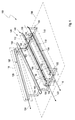
- Figure 1 shows an apparatus 100 for electrostatically discharging a primary packaging container 102 ( Figure 2 ) made of plastics.
- the primary packaging container 102 may be a bottle comprising a volume of two liters, wherein the bottle is made of fluorinated ethylene propylene.
- the apparatus 100 comprises at least one electrode 104.
- the electrode 104 is adapted to generate ionized air in the vicinity of the electrode 104.
- the electrode 104 may be a discharging electrode commercially available under the product name R50 or R51 from the company Eltex-Elektrostatik-GmbH, Blauen Avenue 67-69, 79576 Weil am Rhein, Germany.
- the apparatus 100 may comprise a plurality of electrodes 104, 106, 108.
- the apparatus 100 comprises a first electrode 104, a second electrode 106 and a third electrode 108.
- Each of the electrodes 104, 106, 108 is adapted to generate ionized air in the vicinity thereof.
- first”, second and third are not intended to provide a specific meaning or order of importance but are merely intended to allow to differentiate between the respective electrodes.
- the electrodes 104, 106, 108 are located within planes 110, 112, 114 which are parallel to one another. Particularly, the planes 110, 112, 114 are evenly spaced apart from one another.
- the first electrode 104 comprises a first longitudinal direction 116, which is a direction parallel to a first predetermined length 118 thereof.
- the second electrode 106 comprises a second longitudinal direction 120, which is a direction parallel to a second predetermined length 122 thereof.
- the third electrode 108 comprises a third longitudinal direction 124, which is a direction parallel to a third predetermined length 126 thereof. It is to be noted that at least the first predetermined length 118 and the second predetermined length 122 are of equal size or dimension.
- the first predetermined length 118 corresponds to at least a circumference of the primary packaging container 102.
- the first predetermined length 118 is determined based on the diameter and the circumference, respectively of the primary packaging container 102.
- a larger primary packaging container 102 usually comprises a larger diameter and, therefore, a larger circumference.
- a larger primary packaging container 102 having a larger circumference requires the first predetermined length 118 to be larger in order to allow the primary packaging container 102 to be rotated a complete circumference in the vicinity of the at least one electrode 104.
- At least one of the plurality of electrodes 104, 106, 108 is inclined relative to the other electrodes as shown in Figure 1 .
- the longitudinal direction 116, 120, 124 of one of the electrodes 104, 106, 108 may deviate from the other longitudinal directions 116, 120, 124 within the planes 110, 112, 114.
- the first longitudinal direction 116 of the first electrode 104 and the second longitudinal direction 120 of the second electrode 106 are parallel to one another whereas the third longitudinal direction 124 is inclined thereto.
- the third electrode 108 is the rearmost electrode.
- the apparatus 100 further comprises a moving path 128 for moving the primary packaging container 102 to be electrostatically discharged.
- the moving path 128 is formed such that the primary packaging container 102 is adapted to pass the at least one electrode 104 and to be rotated in the vicinity thereof so as to be contacted by the ionized air as will be explained in further detail below.
- the moving path 128 is formed such that the primary packaging container 102 may pass the at least one electrode 104 and may be rotated in the vicinity thereof so as to be contacted by the ionized air.
- the moving path 128 is formed such that the primary packaging container 102 is adapted to pass each of the electrodes 104, 106, 108 and to be rotated in the vicinity thereof so as to be contacted by the ionized air.
- the moving path 128 comprises rails 130 on which the primary packaging container 102 is movable.
- the rails 130 are arranged with a predetermined distance 132 to the at least one electrode 104. In case there is only one electrode 104, the rails 130 are arranged such that the electrode 104 is in the middle between and below the rails 130.
- the predetermined distance 132 is defined between the electrodes 104, 106, 108 and the rails 130 adjacent to or next to the respective electrode 104, 106, 108.
- the distance 132 may be in a range from 1 cm to 25 cm, preferably from 2 cm to 20 cm, and more preferably from 3 cm to 17 cm such as 9 cm.
- the rails 130 comprise a portion 134 which is arranged with a constant distance 132 to the at least one electrode 104 over the length 118 of the electrode 104. In the present embodiment, only the distance 132 between the first electrode 104 and the portion 134 of the rails 130 and the distance 132 between the second electrode 106 and the portion 134 of the rails 130 are constant. The distance 132 may be variable.
- the rails 130 may be manually moved.
- the rails 130 may be arranged on a supporting structure such as a frame which comprises an adjusting mechanism 135 for adjusting the position of the rails 130.
- the adjustment of the positions of the rails 130 comprises both an adjustment of the distance 132 of the rails 130 relative to the electrodes 104, 106 and an adjustment of the rails 130 relative to one another.
- the adjusting mechanism 135 may comprise tubes of the frame which may be moved relative to one another such that one of the tubes may be moved into and out of the other tube and a fixing means such as screw for fixing the tubes in their position.
- the rails 130 may be moved by means of an actuator (not shown in detail). Even in this case, the rails 130 are moved such that the above distance 132 to the portion 134 will be constant over the length of the at least one electrode 104. Needless to say, the first electrode 104 and the second electrode 106 may also be moved in a similar manner.
- the portion 134 of the rails 130 is parallel to the first and second longitudinal directions 116, 120 of the first electrode 104 and the second electrode 106.
- a movement of the rails 130 allows an adaption of the moving path 128 to the respective size and/or height of the primary packaging container 102 to be discharged.
- the respective size or amount of air which is ionized in the vicinity of the first electrode 104 and the second electrode 106 may be adjusted.
- the moving path 128 comprises an inclination 136.
- a portion of the moving path 128 is inclined with respect to a plane 138 perpendicular to the direction of gravity.
- the portion 134 of the rails 130 is inclined with respect to the plane 138 perpendicular to the direction of gravity.
- the inclination may be an angle of 20 °.
- the moving path 128 comprises a start portion 140, at which a primary packaging container 102 to be discharged is disposable before being discharged, and an end portion 142 at which the primary packaging container 102 is removable after being discharged.
- the start portion 140 is arranged higher than the end portion 142 with respect to the direction of gravity.
- the start portion 140 is arranged at the right and the end portion 142 is arranged at the left.
- the at least one electrode 104 is parallel to the portion 134.
- the first electrode 104 and the second electrode 106 are inclined so as to be parallel to the portion 134 of the rails 130. Due to the inclination 136, the moving path 128 is formed such that the primary packaging container 102 is moveable by means of gravity.
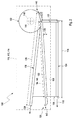
- Figure 2 shows a side view of the apparatus 100 with the primary packaging container 102 arranged on the moving path 128. More particularly, the primary, packaging container 102 is disposed at the start portion 140.
- the primary packaging container 102 comprises a longitudinal axis 144.
- the moving path 128 is formed such that the primary packaging container 102 is rotatable at least one complete rotation around the longitudinal axis 144 in the portion 134 of the rails 130.
- the moving path 128 is formed such that the primary packaging container 102 is rotatable 1.5 rotations around the longitudinal axis 144 in the portion 134 of the rails 130.
- the portion 134 of the rails 130 comprises a length 146 corresponding to at least a circumference of the primary packaging container 102.
- the length 146 is determined based on the diameter and the circumference, respectively of the primary packaging container 102.
- a larger primary packaging container 102 usually comprises a larger diameter and, therefore, a larger circumference.
- a larger primary packaging container 102 having a larger circumference requires the length 146 to be larger in order to allow the primary packaging container 102 to be rotated a complete circumference around its longitudinal axis 144 in the portion 134 of the rails 130.
- the moving path 128 comprises the inclination 136 such that the primary packaging container 102 is allowed to be rotated when moving in the portion 134 caused by gravity.
- the electrodes 104, 106, 108 is arranged such that the primary packaging container 102 is adapted to pass the one electrode 104, 106, 108 with a complete cross-section area perpendicular to the longitudinal axis 144 of the primary packaging container 102.
- the third electrode 108 is arranged inclined with respect to the moving path 128 and the first electrode 104 and the second electrode 106 as shown in Figure 2 . Needless to say, the inclination of the third electrode 108 may be varied. For example, the inclination of the third electrode 108 may be adapted to the size or diameter of the primary packaging container 102.
- the primary packaging container 102 when the primary packaging container 102 moves from the start portion 140 to the end portion 142 while the third electrode 108 is operated, the cross-section of the primary packaging container 102 is intersected by the third electrode 108 if seen in a projection in a direction parallel to the longitudinal axis 144 of the primary packaging container 102. Thus, a bottom and/or a top of the primary packaging container 102 may be discharged.
- the primary packaging container 102 may comprises a closure 148.
- the moving path 128 is formed such that the primary packaging container 102 is moveable such that the closure 148 faces the third electrode 108.
- the primary packaging container 102 may be discharged at the closure 148 and the portions adjacent thereto when the primary packaging container 102 moves from the start portion 140 to the end portion 142 while the third electrode 108 is operated.
- further electrodes may be present.
- a fourth electrode (not shown in detail) may be located parallel to the third electrode 108 with the first electrode 104 and the second electrode 106 therebetween.
- a bottom and a top of the primary packaging container 102 may be discharged.
- the inclination of the fourth electrode may be varied.
- the inclination of the fourth electrode may be adapted to the size or diameter of the primary packaging container 102.
- the primary packaging container 102 may be a bottle with a volume of two liters and may be made of fluorinated ethylene propylene.
- the primary packaging container 102 may be the one as described above.
- the primary packaging container 102 is arranged on the moving path 128 at the start portion 140.
- the primary packaging container 102 is arranged on the moving path 128 such that the closure 148 faces the third electrode 108.
- an alternating voltage is applied to the at least one electrode 104 such that the at least one electrode 104 generates ionized air in the vicinity thereof.
- an alternating voltage is applied to the first electrode 104, to the second electrode 106 and to the third electrode 108 such that the electrodes 106, 108, 110 generate ionized air in the vicinity thereof.
- the amount of the alternating voltage may be in a range of 4 kV to 12 kV such as 8 kV.
- the frequency of the alternating voltage may be 50 Hz.
- the primary packaging container 102 is allowed to move towards the end portion 142.
- the primary packaging container 102 is released and is allowed to move towards the end portion 142 by means of gravity and due to the inclination 136.
- the primary packaging container 102 moves on the rails 130 by means of gravity.
- the primary packaging container 102 passes the at least one electrode 104. More particularly, in the present embodiment, the primary packaging container 102 passes the first electrode 104, the second electrode 106 and the third electrode 108 at the same time. This moving direction corresponds to a moving from the right to the left according to the illustration of Figure 2 .
- the primary packaging container 102 is rotated in the vicinity of the electrodes 104, 106, 108 on the rails 130 in the portion 134 and contacted by the ionized air. Due to the specific arrangement of the moving path 128 and the electrodes 104, 106, 108, the primary packaging container 102 is moved so as to pass the at least one electrode 104 with the predetermined distance 132 to the at least one electrode 104. In the present embodiment, the primary packaging container 102 is moved so as to pass the first electrode 104 and the second electrode 106 with the predetermined distance 132 to the first electrode 104 and the second electrode 106.
- the moving path 128 is formed such that the primary packaging container 102 is rotated at least one complete rotation around the longitudinal axis 144 in the vicinity of the electrodes 104, 106, 108, while being contacted by the ionized air.
- the primary packaging container 102 fulfills 1.5 rotations around the longitudinal axis 144 when moving on the moving path 128.
- it is ensured that at least the complete outer circumferential surface of the primary packaging container 102 is electrostatically discharged.
- the inner circumferential surface of the primary packaging container 102 is electrostatically discharged.
- the primary packaging container 102 is moved parallel to the first longitudinal direction 116 of the first electrode 104. It is to be noted that in the present embodiment, the primary packaging container 102 is also moved parallel to the second longitudinal direction 120 of the second electrode 106 as the first longitudinal direction 116 and the second longitudinal direction 120 are parallel to one another. As described above, the third electrode 108 is arranged inclined with respect to the first electrode 104 and the second electrode 106. Thus, during moving on the moving path 128, the primary packaging container 102 passes this one electrode 108 with a complete cross-sectional area perpendicular to the longitudinal axis 144 of the primary packaging container 102.
- the primary packaging container 102 when the primary packaging container 102 moves from the start portion 140 to the end portion 142 while the third electrode 108 is operated, the cross-section of the primary packaging container 102 is intersected by the third electrode 108 if seen in a projection in a direction parallel to the longitudinal axis 144 of the primary packaging container 102.
- the primary packaging container 102 comprises the closure 148.
- the primary packaging container 102 is arranged on the moving path 128 such that the closure 148 faces the third electrode 108.
- the primary packaging container 102 When the primary packaging container 102 moves from the start portion 140 to the end portion 142, the primary packaging container 102 is discharged at the closure 148 and the portions adjacent thereto while the third electrode 108 is operated.
- the primary packaging container 102 is electrostatically discharged by means of the first electrode 104 and the second electrode 106 but the top side of the primary packaging container 102 is electrostatically discharged by means of the third electrode 108. Accordingly, essential portions of the primary packaging container 102 may be effectively electrostatically discharged by means of the apparatus 100 and the method according to the present invention. More particularly, the electrostatical charge of the primary packaging container 102 may be reduced below -200 V such that particles do not adhere thereto.
- a table which indicates measurement results of voltage after the apparatus 100 has electrostatically discharged primary packaging containers 102.
- the primary packaging container 102 have been electrostatically charged to a voltage of -25 kV before using the apparatus 100 in order to electrostatically charge the primary packaging containers 102 to a significant amount.
- the primary packaging containers 102 used for the measurements were bottles comprising a volume of two liters, wherein the bottles are made of fluorinated ethylene propylene.
- the measurement points at the primary packaging containers 102 were evenly distributed along the height and the circumferential direction of the bottles.
- the number of the primary packaging containers 102 is indicated in the first column from the left.
- the total number of primary packaging containers 102 was 13. It is to be noted that the primary packaging containers 102 numbers 1 to 13 have been electrostatically discharged while the first to third electrodes 104, 106, 108 have been operated. Regarding the primary packaging containers 102 numbers 7 to 13, these have been removed from the apparatus 100 after having been electrostatically discharged such that the bottom thereof faces the first electrode 104 and the second electrode 106 for a short period. The respective measurement results are given as a positive voltage even though the voltage is actually negative.
- a voltage of 36 V is given for the measurement point front and top even though the actual voltage is -36 V.
- Table 1 No. front right rear left above top below bottom top middle bottom top middle bottom top middle bottom top middle bottom top middle bottom 1 36 40 60 30 7 9 59 26 28 22 12 13 78 220 2 48 14 47 6 35 0 4 20 13 6 7 51 110 240 3 92 32 22 30 48 8 0 0 9 101 83 87 133 561 4 0 14 15 0 20 38 90 0 45 21 0 0 120 230 5 180 35 140 29 12 45 13 2 0 6 13 15 140 606 6 15 6 80 14 20 7 0 14 7 17 130 140 150 570 7 30 17 30 24 18 78 15 19 76 3 35 66 130 200 8 22 17 22 15 8 12 0 18 0 0 24 0 88 220 9 10 15 0 19 13 48 90 15 22 80 2 0 157 85 10 21 17 3 0 9 43 66 33 70 100 5 7 150 101 11 27 6 8 14 3
- the apparatus is suitable to electrostatically discharge the primary packaging containers 102 at each height of the measurement points front, right, rear and left to an amount significantly less than -200 V.
- operation of the third electrode 108 allows to ensure that the bottom is electrostatically discharged to an amount of approximately -200 V and less.
Landscapes
- Health & Medical Sciences (AREA)
- General Health & Medical Sciences (AREA)
- Toxicology (AREA)
- Elimination Of Static Electricity (AREA)
- Packaging Frangible Articles (AREA)
Priority Applications (7)
| Application Number | Priority Date | Filing Date | Title |
|---|---|---|---|
| EP15161877.4A EP3076766A1 (de) | 2015-03-31 | 2015-03-31 | Verfahren und vorrichtung zur elektrostatischen entladung eines primärverpackungsbehälters aus kunststoff |
| EP16713379.2A EP3278635B1 (de) | 2015-03-31 | 2016-03-24 | Verfahren und vorrichtung zur elektrostatischen entladung eines primärverpackungsbehälters aus kunststoff |
| JP2017551035A JP6695354B2 (ja) | 2015-03-31 | 2016-03-24 | プラスチック製の一次包装容器を静電気放電するための方法および装置 |
| PCT/EP2016/056599 WO2016156229A1 (en) | 2015-03-31 | 2016-03-24 | Method and apparatus for electrostatically discharging a primary packaging container made of plastics |
| HK18104070.5A HK1244992B (zh) | 2015-03-31 | 2016-03-24 | 用於使由塑料制成的初级包装容器静电放电的方法和设备 |
| CN201680019461.0A CN107409463B (zh) | 2015-03-31 | 2016-03-24 | 用于使由塑料制成的初级包装容器静电放电的方法和设备 |
| US15/720,241 US10548207B2 (en) | 2015-03-31 | 2017-09-29 | Method and apparatus for electrostatically discharging a primary packaging container made of plastics |
Applications Claiming Priority (1)
| Application Number | Priority Date | Filing Date | Title |
|---|---|---|---|
| EP15161877.4A EP3076766A1 (de) | 2015-03-31 | 2015-03-31 | Verfahren und vorrichtung zur elektrostatischen entladung eines primärverpackungsbehälters aus kunststoff |
Publications (1)
| Publication Number | Publication Date |
|---|---|
| EP3076766A1 true EP3076766A1 (de) | 2016-10-05 |
Family
ID=52813948
Family Applications (2)
| Application Number | Title | Priority Date | Filing Date |
|---|---|---|---|
| EP15161877.4A Withdrawn EP3076766A1 (de) | 2015-03-31 | 2015-03-31 | Verfahren und vorrichtung zur elektrostatischen entladung eines primärverpackungsbehälters aus kunststoff |
| EP16713379.2A Not-in-force EP3278635B1 (de) | 2015-03-31 | 2016-03-24 | Verfahren und vorrichtung zur elektrostatischen entladung eines primärverpackungsbehälters aus kunststoff |
Family Applications After (1)
| Application Number | Title | Priority Date | Filing Date |
|---|---|---|---|
| EP16713379.2A Not-in-force EP3278635B1 (de) | 2015-03-31 | 2016-03-24 | Verfahren und vorrichtung zur elektrostatischen entladung eines primärverpackungsbehälters aus kunststoff |
Country Status (5)
| Country | Link |
|---|---|
| US (1) | US10548207B2 (de) |
| EP (2) | EP3076766A1 (de) |
| JP (1) | JP6695354B2 (de) |
| CN (1) | CN107409463B (de) |
| WO (1) | WO2016156229A1 (de) |
Citations (3)
| Publication number | Priority date | Publication date | Assignee | Title |
|---|---|---|---|---|
| US4701973A (en) * | 1984-08-27 | 1987-10-27 | William J. McBrady | Bottle duster |
| EP2269943A2 (de) * | 2009-06-30 | 2011-01-05 | Shibuya Kogyo Co., Ltd. | Verfahren zur Eliminierung der statischen Ladung von einem Harzgefäß |
| US20110100401A1 (en) * | 2008-05-14 | 2011-05-05 | Gerresheimer Pisa S.P.A | Method and device for removing contaminating particles from containers |
Family Cites Families (9)
| Publication number | Priority date | Publication date | Assignee | Title |
|---|---|---|---|---|
| DE1963248B2 (de) * | 1969-12-17 | 1972-02-17 | Verfahren und vorrichtung zur erhoehung der ladungsdichte auf der oberflaeche eines elektrisch nicht leitenden materials | |
| US4709297A (en) * | 1984-06-29 | 1987-11-24 | Siemens Aktiengesellschaft | Guiding device for semiconductor components with DIL casings |
| US4883542A (en) * | 1987-12-22 | 1989-11-28 | John Voneiff | Method and apparatus for cleaning containers |
| US5265298A (en) * | 1992-02-25 | 1993-11-30 | Raymond Young | Container cleaning system using ionized air flow |
| DE10211976A1 (de) * | 2002-03-19 | 2003-10-02 | Bosch Gmbh Robert | Verfahren und Vorrichtung zumindest zur Sterilisation von Behältnissen und/oder deren Verschließelementen |
| JP2003291927A (ja) * | 2002-04-05 | 2003-10-15 | Aisan Seisakusho:Kk | カップの集塵装置 |
| US7621301B2 (en) | 2006-04-13 | 2009-11-24 | The Quaker Oats Company | Method of ionized air-rinsing of containers and apparatus therefor |
| CN203408931U (zh) * | 2013-06-27 | 2014-01-29 | 天津市福奇特电子有限公司 | 滚动式离子风除屑机 |
| CN204217194U (zh) * | 2014-10-27 | 2015-03-18 | 天津瑞杰塑料制品有限公司 | 一种塑料容器除静电装置 |
-
2015
- 2015-03-31 EP EP15161877.4A patent/EP3076766A1/de not_active Withdrawn
-
2016
- 2016-03-24 EP EP16713379.2A patent/EP3278635B1/de not_active Not-in-force
- 2016-03-24 WO PCT/EP2016/056599 patent/WO2016156229A1/en not_active Ceased
- 2016-03-24 CN CN201680019461.0A patent/CN107409463B/zh not_active Expired - Fee Related
- 2016-03-24 JP JP2017551035A patent/JP6695354B2/ja not_active Expired - Fee Related
-
2017
- 2017-09-29 US US15/720,241 patent/US10548207B2/en not_active Expired - Fee Related
Patent Citations (3)
| Publication number | Priority date | Publication date | Assignee | Title |
|---|---|---|---|---|
| US4701973A (en) * | 1984-08-27 | 1987-10-27 | William J. McBrady | Bottle duster |
| US20110100401A1 (en) * | 2008-05-14 | 2011-05-05 | Gerresheimer Pisa S.P.A | Method and device for removing contaminating particles from containers |
| EP2269943A2 (de) * | 2009-06-30 | 2011-01-05 | Shibuya Kogyo Co., Ltd. | Verfahren zur Eliminierung der statischen Ladung von einem Harzgefäß |
Also Published As
| Publication number | Publication date |
|---|---|
| WO2016156229A1 (en) | 2016-10-06 |
| HK1244992A1 (zh) | 2018-08-17 |
| CN107409463B (zh) | 2020-04-03 |
| US20180027639A1 (en) | 2018-01-25 |
| JP6695354B2 (ja) | 2020-05-20 |
| EP3278635A1 (de) | 2018-02-07 |
| US10548207B2 (en) | 2020-01-28 |
| CN107409463A (zh) | 2017-11-28 |
| JP2018512713A (ja) | 2018-05-17 |
| EP3278635B1 (de) | 2021-12-15 |
Similar Documents
| Publication | Publication Date | Title |
|---|---|---|
| EP2650022B1 (de) | Vorrichtung und Verfahren zum strahlungsbasierten Sterilisieren von Behältnisverschlüssen | |
| JP5564039B2 (ja) | 自動製造ライン上の容器から残留物質および/または粒子を除去する方法および装置 | |
| US8505269B2 (en) | Method, apparatus and system of eliminating static charge and filling and sterilizing resin vessel | |
| WO2019121723A1 (de) | Vorrichtung zum behandeln von behältern | |
| AT10979U1 (de) | Sortiervorrichtung | |
| EP4313540B1 (de) | Vorrichtung und verfahren zum herstellen von geformten, befüllten und verschlossenen behältererzeugnissen aus kunststoffmaterial | |
| EP3278635B1 (de) | Verfahren und vorrichtung zur elektrostatischen entladung eines primärverpackungsbehälters aus kunststoff | |
| US11987410B2 (en) | Procedure for the filling of solids in pharmaceutical containers and the sealing thereof under sterile conditions | |
| US20240359837A1 (en) | High-Speed Container Filling with Reduced Cross-Contamination | |
| EP2461980B1 (de) | Vorrichtung und verfahren zur oberflächenbearbeitung mit einer prüfstation | |
| TW201246264A (en) | Ion beam irradiation method and ion beam irradiation system | |
| CN111315679A (zh) | 用于处理容器封闭件的装置 | |
| EP3732108B1 (de) | Verpackungseinrichtung sowie ein verfahren zum betreiben einer verpackungseinrichtung | |
| EP1487502B1 (de) | Verfahren und vorrichtung zumindest zur sterilisation von verschliesselementen für behaeltnisse | |
| HK1244992B (zh) | 用於使由塑料制成的初级包装容器静电放电的方法和设备 | |
| KR100969348B1 (ko) | 탈자 장치 | |
| US20210371210A1 (en) | Switch device | |
| JP2017035670A (ja) | 選別装置 | |
| DE102023125204A1 (de) | Vorrichtung zum Behandeln von Mehrwegbehältern | |
| KR20170080394A (ko) | 전기적 이동도 기반의 입자 크기 분류 장치 | |
| JP2002083700A (ja) | 交流式イオナイザ | |
| Mahr et al. | Control and Reduction of Foreign Particles in the Manufacturing Process of a Dry Powder Inhaler Product–Applying a Quality by Design Strategy Based on IPAC-RS Recommendations | |
| KR20160148095A (ko) | 와이어 형태의 전극을 이용한 정전기 제거 장치 |
Legal Events
| Date | Code | Title | Description |
|---|---|---|---|
| PUAI | Public reference made under article 153(3) epc to a published international application that has entered the european phase |
Free format text: ORIGINAL CODE: 0009012 |
|
| AK | Designated contracting states |
Kind code of ref document: A1 Designated state(s): AL AT BE BG CH CY CZ DE DK EE ES FI FR GB GR HR HU IE IS IT LI LT LU LV MC MK MT NL NO PL PT RO RS SE SI SK SM TR |
|
| AX | Request for extension of the european patent |
Extension state: BA ME |
|
| STAA | Information on the status of an ep patent application or granted ep patent |
Free format text: STATUS: THE APPLICATION HAS BEEN PUBLISHED |
|
| STAA | Information on the status of an ep patent application or granted ep patent |
Free format text: STATUS: THE APPLICATION IS DEEMED TO BE WITHDRAWN |
|
| 18D | Application deemed to be withdrawn |
Effective date: 20170406 |