EP3076103A1 - Assembly of parts and assembly for fastening at least one photovoltaic module and method for producing an assembly of parts - Google Patents
Assembly of parts and assembly for fastening at least one photovoltaic module and method for producing an assembly of parts Download PDFInfo
- Publication number
- EP3076103A1 EP3076103A1 EP16163105.6A EP16163105A EP3076103A1 EP 3076103 A1 EP3076103 A1 EP 3076103A1 EP 16163105 A EP16163105 A EP 16163105A EP 3076103 A1 EP3076103 A1 EP 3076103A1
- Authority
- EP
- European Patent Office
- Prior art keywords
- subassembly
- connecting element
- photovoltaic module
- holding
- side connecting
- Prior art date
- Legal status (The legal status is an assumption and is not a legal conclusion. Google has not performed a legal analysis and makes no representation as to the accuracy of the status listed.)
- Withdrawn
Links
- 238000004519 manufacturing process Methods 0.000 title abstract description 9
- 238000000034 method Methods 0.000 claims description 11
- 239000004020 conductor Substances 0.000 claims description 4
- 238000000429 assembly Methods 0.000 description 7
- 229910052782 aluminium Inorganic materials 0.000 description 4
- XAGFODPZIPBFFR-UHFFFAOYSA-N aluminium Chemical compound [Al] XAGFODPZIPBFFR-UHFFFAOYSA-N 0.000 description 4
- 238000009434 installation Methods 0.000 description 4
- 229910001220 stainless steel Inorganic materials 0.000 description 4
- 239000010935 stainless steel Substances 0.000 description 4
- 229910052751 metal Inorganic materials 0.000 description 3
- 239000002184 metal Substances 0.000 description 3
- 239000000969 carrier Substances 0.000 description 2
- 150000001875 compounds Chemical class 0.000 description 2
- 238000001125 extrusion Methods 0.000 description 2
- 230000010354 integration Effects 0.000 description 2
- 230000000717 retained effect Effects 0.000 description 2
- 238000010079 rubber tapping Methods 0.000 description 2
- 238000003491 array Methods 0.000 description 1
- 238000005452 bending Methods 0.000 description 1
- 238000005260 corrosion Methods 0.000 description 1
- 230000007797 corrosion Effects 0.000 description 1
- 238000005520 cutting process Methods 0.000 description 1
- 230000001419 dependent effect Effects 0.000 description 1
- 238000009413 insulation Methods 0.000 description 1
- 239000000463 material Substances 0.000 description 1
- 238000002360 preparation method Methods 0.000 description 1
- 239000007787 solid Substances 0.000 description 1
- 230000003068 static effect Effects 0.000 description 1
- 238000003860 storage Methods 0.000 description 1
- 239000000758 substrate Substances 0.000 description 1
Images


Classifications
-
- F—MECHANICAL ENGINEERING; LIGHTING; HEATING; WEAPONS; BLASTING
- F24—HEATING; RANGES; VENTILATING
- F24S—SOLAR HEAT COLLECTORS; SOLAR HEAT SYSTEMS
- F24S25/00—Arrangement of stationary mountings or supports for solar heat collector modules
- F24S25/60—Fixation means, e.g. fasteners, specially adapted for supporting solar heat collector modules
- F24S25/65—Fixation means, e.g. fasteners, specially adapted for supporting solar heat collector modules for coupling adjacent supporting elements, e.g. for connecting profiles together
-
- H—ELECTRICITY
- H02—GENERATION; CONVERSION OR DISTRIBUTION OF ELECTRIC POWER
- H02S—GENERATION OF ELECTRIC POWER BY CONVERSION OF INFRARED RADIATION, VISIBLE LIGHT OR ULTRAVIOLET LIGHT, e.g. USING PHOTOVOLTAIC [PV] MODULES
- H02S20/00—Supporting structures for PV modules
- H02S20/30—Supporting structures being movable or adjustable, e.g. for angle adjustment
-
- F—MECHANICAL ENGINEERING; LIGHTING; HEATING; WEAPONS; BLASTING
- F24—HEATING; RANGES; VENTILATING
- F24S—SOLAR HEAT COLLECTORS; SOLAR HEAT SYSTEMS
- F24S25/00—Arrangement of stationary mountings or supports for solar heat collector modules
- F24S25/30—Arrangement of stationary mountings or supports for solar heat collector modules using elongate rigid mounting elements extending substantially along the supporting surface, e.g. for covering buildings with solar heat collectors
- F24S25/33—Arrangement of stationary mountings or supports for solar heat collector modules using elongate rigid mounting elements extending substantially along the supporting surface, e.g. for covering buildings with solar heat collectors forming substantially planar assemblies, e.g. of coplanar or stacked profiles
- F24S25/35—Arrangement of stationary mountings or supports for solar heat collector modules using elongate rigid mounting elements extending substantially along the supporting surface, e.g. for covering buildings with solar heat collectors forming substantially planar assemblies, e.g. of coplanar or stacked profiles by means of profiles with a cross-section defining separate supporting portions for adjacent modules
-
- F—MECHANICAL ENGINEERING; LIGHTING; HEATING; WEAPONS; BLASTING
- F24—HEATING; RANGES; VENTILATING
- F24S—SOLAR HEAT COLLECTORS; SOLAR HEAT SYSTEMS
- F24S25/00—Arrangement of stationary mountings or supports for solar heat collector modules
- F24S2025/80—Special profiles
- F24S2025/803—Special profiles having a central web, e.g. I-shaped, inverted T- shaped
-
- F—MECHANICAL ENGINEERING; LIGHTING; HEATING; WEAPONS; BLASTING
- F24—HEATING; RANGES; VENTILATING
- F24S—SOLAR HEAT COLLECTORS; SOLAR HEAT SYSTEMS
- F24S25/00—Arrangement of stationary mountings or supports for solar heat collector modules
- F24S2025/80—Special profiles
- F24S2025/804—U-, C- or O-shaped; Hat profiles
-
- Y—GENERAL TAGGING OF NEW TECHNOLOGICAL DEVELOPMENTS; GENERAL TAGGING OF CROSS-SECTIONAL TECHNOLOGIES SPANNING OVER SEVERAL SECTIONS OF THE IPC; TECHNICAL SUBJECTS COVERED BY FORMER USPC CROSS-REFERENCE ART COLLECTIONS [XRACs] AND DIGESTS
- Y02—TECHNOLOGIES OR APPLICATIONS FOR MITIGATION OR ADAPTATION AGAINST CLIMATE CHANGE
- Y02E—REDUCTION OF GREENHOUSE GAS [GHG] EMISSIONS, RELATED TO ENERGY GENERATION, TRANSMISSION OR DISTRIBUTION
- Y02E10/00—Energy generation through renewable energy sources
- Y02E10/40—Solar thermal energy, e.g. solar towers
- Y02E10/47—Mountings or tracking
-
- Y—GENERAL TAGGING OF NEW TECHNOLOGICAL DEVELOPMENTS; GENERAL TAGGING OF CROSS-SECTIONAL TECHNOLOGIES SPANNING OVER SEVERAL SECTIONS OF THE IPC; TECHNICAL SUBJECTS COVERED BY FORMER USPC CROSS-REFERENCE ART COLLECTIONS [XRACs] AND DIGESTS
- Y02—TECHNOLOGIES OR APPLICATIONS FOR MITIGATION OR ADAPTATION AGAINST CLIMATE CHANGE
- Y02E—REDUCTION OF GREENHOUSE GAS [GHG] EMISSIONS, RELATED TO ENERGY GENERATION, TRANSMISSION OR DISTRIBUTION
- Y02E10/00—Energy generation through renewable energy sources
- Y02E10/50—Photovoltaic [PV] energy
Definitions
- the invention relates to a subassembly and an arrangement for mounting a photovoltaic module and to a method for producing a subassembly.
- substructures When mounting photovoltaic modules on open spaces usually so-called substructures are needed to which the photovoltaic modules can be mounted in a desired location and with a desired orientation. For a desired installation site therefore usually elements of the substructure must be specially made or adapted for assembly. This requires a costly and time-consuming provision of such a substructure.
- the JP 2014-037685 A discloses a method of installing a photovoltaic module.
- supporting elements are used, wherein some of these support elements are covered by cover elements.
- the EP 2 642 218 A1 discloses a modular device for architectural integration of frameless solar modules.
- the DE 10 2011 007 521 A1 discloses a substructure for a solar module free-field arrangement, in particular an arrangement of frameless solar modules. This includes module carriers and upper connection brackets for connecting module carriers.
- the DE 20 2009 014 723 U1 discloses a steel-made solar module support structure consisting of two arches of different height.
- the US 2010/096073 A discloses a method and apparatus for solar module installation.
- the photovoltaic module can also be referred to as a solar module.
- the photovoltaic module may in particular be a framed photovoltaic module.
- the frame may in this case be a metallic frame, which is coated with an electrically insulating insulation layer, for example an anodized layer.
- the subassembly may be part of an arrangement for mounting such a photovoltaic module.
- the subassembly comprises a first retaining profile element and at least one further retaining profile element.
- a holding profile element here denotes an element for holding the photovoltaic module.
- Such a retaining profile element may in particular be made of metal, preferably aluminum.
- a holding profile element can be produced in a so-called extrusion process.
- a retaining profile may in this case be an elongated element, wherein a retaining profile element may have a predetermined length. The length may for example be in a range of 500 mm to 1500 mm.
- a holding profile element can have or form at least one holding section for holding the photovoltaic module.
- the holding section can be designed, for example, as a section for supporting or mounting the photovoltaic module, in particular an edge section or a section of the frame on one side of the photovoltaic module.
- the retaining profile element for example, a support surface for supporting a bottom of the edge portion or a portion of the edge portion, in particular a bottom of the frame, have or form.
- the retaining profile element may in this case comprise a plurality of sub-elements, which need not necessarily be connected. However, in each case sections of the same side of the photovoltaic module are supported by the sub-elements of a holding profile element.
- the first and the at least one further retaining profile element may have the same design.
- the subassembly may comprise more than two retaining profile elements, for example up to 10 retaining profile elements.
- the subassembly comprises at least a first underside connecting element and at least one first top side connecting element.
- a bottom link may also be referred to as a so-called bottom chord and a top link as a so-called top chord.
- a retaining profile element may have a bottom and a top.
- On or in the lower or upper side means may be formed or arranged for fastening the lower side connecting element or the upper side connecting element.
- the underside connecting element is connected to lower sides of the first and further retaining profile element. This can mean that both the underside of the first retaining profile element and the underside of the further retaining profile element is connected to the underside connecting element. Further, this may mean that the underside connecting element is connected to the underside of the retaining profile element with the retaining profile element.
- the feature "connected” may mean that a non-positive, cohesive and / or positive connection exists.
- the compound may in this case be a detachable or insoluble compound.
- first upper side connecting element is connected to upper sides of the first and further retaining profile element.
- first Top link is connected to both the top of the first and with the top of the further retaining profile element.
- top side connection element is connected to the top side of the retaining profile element with the retaining profile element.
- the top connector and / or the bottom connector may each include one or more through holes and / or one or more threaded holes that serve to connect the member to the top and bottom, respectively.
- the holding profile elements are connected to each other via the lower side connecting elements as well as via the upper side connecting elements. If the retaining profile elements are connected to one another in such a way, there is a connected state.
- the first upper-side connecting element is configured and connectable to the retaining profile elements such that a photovoltaic module which can be held by the first retaining profiled element and / or a photovoltaic module which can be retained by the further retaining profiled element can be connected to the retaining profiled element by the first upper-side connecting element.
- the first upper-side connection element can be designed and connectable to the retaining profile elements in such a way that one or two photovoltaic modules can be fastened to the first retaining profile element and / or another or two further photovoltaic modules can be fastened to the further retaining profile element.
- the first upper-side connection element may have contact surfaces for contacting an upper side of one or two photovoltaic modules, in particular an upper side of an edge section or frame of the photovoltaic module (s).
- the upper side connecting member may have a connecting portion for connecting these contact portions. If the upper side connecting element is connected to the upper side of the first and / or further holding profile element, the contact sections can each come into contact with a photovoltaic module.
- a photovoltaic module may be connected to the substrate during connection of the top side connector Holding profile elements between the holding portion of the holding profile element and the respective contact portion of the upper side connecting element are clamped.
- the attachment of the photovoltaic module to the retaining profile elements is at least partially by means of the upper side connecting element.
- the upper side connecting element and the lower side connecting element may be formed as separate components.
- both a mechanical stability of the support profile elements consisting of the support profile elements, in particular a high bending stiffness, can be ensured in an advantageous manner, while at the same time enabling reliable fastening of a photovoltaic module to the support structure by the upper side connecting element.
- the subassembly may include more than one bottom link and more than one top link. If the subassembly comprises, for example, n holding profile elements, then the subassembly may comprise n-1 bottom side connecting elements and n-1 top side connecting elements.
- the first and further retaining profile element are angled at a desired angle to each other.
- This arrangement can be given in particular in the connected state.
- the desired angle may designate an angle between central longitudinal axes of the retaining profile elements. This angle may in particular be greater than 0 ° and less than 180 °. Preferably, the angle is in an angular range of 5 ° to 30 °.
- the photovoltaic modules which can be fastened to the retaining profile elements can be mounted with a desired orientation relative to one another and / or relative to the ground, when an assembly comprising the sub-assembly for mounting on a foundation, for example in the ground, is fastened ,
- At least one free end of the first and further retaining profile element is chamfered. That ends of the first and further retaining profile element are chamfered, may mean that end faces of the Holding profile elements include a predetermined angle greater than 0 °, but less than 90 ° with the central longitudinal axis of the corresponding holding profile element. In the connected state, the chamfered ends of the retaining profile elements can rest against each other.
- free ends of the retaining profile elements can be beveled in such a way that, in the connected state, they are angled relative to one another with the desired angle explained above or rest against one another. This results in an advantageous manner, a simple assembly of the retaining profile elements in an angled arrangement.
- the subassembly comprises an element for adjusting the angle between two retaining profile elements.
- the element for adjusting the angle is arranged between free ends, in particular front ends, of the retaining profile elements.
- the adjustment element may have two contact surfaces which are angled at the desired angle to one another. End faces of the first and further retaining profile elements can rest against these contact surfaces.
- the element for adjusting the angle can be formed here as a solid or hollow profile.
- the element for adjusting the angle of an electrically conductive material, in particular metal, preferably aluminum may be formed.
- the element for adjusting the angle may have a triangular or trapezoidal profile in cross section.
- first underside connecting element and / or the first top connecting element is / are formed as an angle profile element.
- a connecting element may have two sections, wherein these sections are arranged at an angle to one another. These sections can in particular be arranged at an angle which is angled relative to one another. Further, these portions may include or form the previously explained contact portions.
- the upper side connecting element and / or the lower side connecting element are / is designed as a sheet metal profile or as a stainless steel profile.
- This profile may for example have a predetermined thickness, for example from a range of 3 mm to 8 mm.
- the first upper-side connecting element has at least one contact means for electrically contacting a frame of the photovoltaic module or forms such a.
- the contact means may in particular be designed such that the electrically conductive part of the frame is contactable.
- the frame of the photovoltaic module can be connected to a potential of the subassembly. If the subassembly is connected to a reference potential, for example a ground potential, an electrical connection between the frame and this electrical reference potential can thereby take place. This results in an advantageous way, a simple grounding of content-supported photovoltaic modules.
- the upper-side connecting element has or forms a contact section, in particular a contact surface, for mechanically contacting a frame of the photovoltaic module.
- the contact means for electrical contacting is formed by the contact portion or is arranged thereon.
- an edge region of a contact surface designed as a contact section can be folded.
- the contact surface When attaching the upper side connecting element to a holding profile element, the contact surface may come into mechanical contact with the surface of the frame, wherein the bent edge portion penetrates the described insulating layer and enters into mechanical as well as electrical contact with the electrically conductive part of the frame.
- a contact means for example, a serrated edge region, a curved edge region or an uneven surface structuring of the upper side connecting element, in particular their contact surface.
- a serrated edge region for example, a curved edge region or an uneven surface structuring of the upper side connecting element, in particular their contact surface.
- at least one pyramidal or a pointed elevations may be provided on the contact surface.
- the retaining profile elements and the upper side connecting element made of electrically conductive material. In this way, it is advantageously ensured that the electrically conductive part of a frame can be connected to a desired reference potential via a top side connecting element and retaining profile element of the subassembly.
- the underside connector may be formed of an electrically conductive material.
- the subassembly is electrically connected to a reference potential, for example a ground potential. This can be done, for example, via an electrical connection of one of the retaining profile elements and / or one of the upper side connecting elements and / or one of the lower side connecting elements with the reference potential. As a result, the subassembly can be grounded in an advantageous manner, which advantageously increases operating reliability.
- a reference potential for example a ground potential.
- the arrangement comprises at least one end bottom side connecting element, wherein the end bottom side connecting element with a Bottom of an end retaining profile element is connected. Further, the end bottom link is connected to a foundation.
- An end retaining profile element may in this case designate a retaining profile element of the subassembly which has one end which is not connected to a further retaining profile element via a bottom side connecting element and / or a top side connecting element. This can thus be connected in an advantageous manner via the end bottom side connecting element with a foundation or another support structure.
- the end underside connecting element may in this case be designed like a lower side connecting element.
- the subassembly may also include one or more end bottom connection elements in addition to one or more bottom side connection elements.
- a foundation member such as a foundation plate
- an end retaining profile member may be attached to a free end of an end retaining profile member.
- retaining profile elements of the subassembly are designed and arranged such that the retaining profile elements form a substantially arcuate, in particular semicircular, subassembly for mounting.
- the fact that the retaining profile elements of the subassembly are designed and arranged in such a way may mean that the subassembly comprises a predetermined number of retaining profile elements of a predetermined length, which are each angled at a desired angle to each other to provide the substantially arcuate subassembly.
- a substantially arcuate subassembly denotes a polygonal structure, in particular a polygon.
- a polygon may be equilateral or equiangular.
- the ideal arc or circular shape is approached, but not achieved.
- the subassembly makes it possible to produce a photovoltaic system which has a flat diurnal line compared to roof mounted photovoltaic systems but no steep peak yield curve.
- a length of a retaining profile element is greater than the length of the side of the photovoltaic module supported by the retaining profile element or equal to this length.
- the supported side may be a longitudinal side or front side of the photovoltaic module.
- Feeder may mean that the side or a frame or section of the frame arranged on the side is arranged in, on or on the explained holding section of the holding profile element.
- the side or side frame or section of the frame may be in, on or on along its entire length be arranged the explained holding portion of the holding profile element. In this case, the stability of the resulting assembly can be improved by the holding profile element.
- the length of a retaining profile element is smaller than the length of the content held by the retaining profile element side of the photovoltaic module.
- the side or the frame or portion of the frame arranged on the side can not be arranged along its entire length in, on or on the explained holding section of the holding profile element. In this case, the stability of the resulting assembly can be ensured by the frame.
- the length of each sub-element or the sum of the lengths of all sub-elements may be smaller than the length of the side of the photovoltaic module supported by the retaining profile element.
- a retaining profile element has a receiving groove on the underside, wherein the underside connecting element is arranged in or outside the receiving groove.
- the arrangement here comprises at least two subassemblies according to one of the embodiments described in this invention.
- the first subassembly is arranged at a distance from a second subassembly.
- the distance can be adapted to a length or width of a photovoltaic module.
- photovoltaic modules can be arranged between the sub-assemblies.
- a photovoltaic module in particular a first edge section, preferably a first section of the frame, can be arranged on a retaining profile element of the first subassembly and fastened to this retaining profile element by means of a top side connecting element of the first subassembly.
- this photovoltaic module in particular a further edge section, preferably a further section of the frame, can be arranged on a retaining profile element of the second subassembly and connected to this retaining profile element via the upper side connecting element of the second subassembly.
- the arranged on the holding profile elements sections of the solar module may in particular be sections of opposite longitudinal or transverse sides of the solar module.
- the arrangement may include more than two sub-assemblies for mounting.
- the various sub-assemblies can be connected exclusively via the arranged between the sub-assemblies photovoltaic module.
- At least one underside connecting element of the first subassembly forms a underside connecting element of the second subassembly.
- at least one upper-side connecting element of the first sub-assembly forms a top-side connecting element of the second sub-assembly.
- one or more, but not all, bottom and / or top connecting members form both a connecting element of the first and the further subassembly.
- such a connecting element can extend from the first subassembly to the second subassembly.
- a connecting element may also be a connecting element of more than two subassemblies.
- At least one photovoltaic module is supported by a holding profile element of the first subassembly and a holding profile element of the second subassembly.
- the at least one photovoltaic module can be fastened to the corresponding retaining profile elements via a top-side connecting element or can be mechanically connected thereto.
- Such an arrangement may also be referred to as a photovoltaic system.
- a method for mounting a subassembly for holding at least one photovoltaic module serves to produce a subassembly according to one of the embodiments described in this invention.
- this method may include all necessary process steps.
- a first retaining profile element at least one further retaining profile element, at least one first lower side connecting element and at least one upper side connecting element are provided.
- the first underside connector is connected to bottoms of the first and further bracket members.
- the first upper side connecting element is connected to upper sides of the first and further retaining profiled element.
- At least one photovoltaic module is arranged on the retaining profile elements before the connection of the upper side connecting element with the upper sides of the first and further retaining profile element. It is conceivable that two photovoltaic modules are arranged on a holding profile element.
- at least one photovoltaic module in particular an edge section, preferably a section of the frame, can be arranged on or at corresponding holding sections of one of the retaining profile elements. Then the photovoltaic modules are connected to the holding profile elements by the connection of the upper side connecting element with the upper sides of the retaining profile elements. This allows the photovoltaic module to be clamped.
- different sections of a photovoltaic module in particular different edge sections, preferably different sections of the frame, can be connected to holding profile elements of different subassemblies, whereby a rigid, self-supporting and statically stable photovoltaic system is provided.
- a frame of at least one photovoltaic module is electrically contacted by the connection of the upper side connecting element with the upper sides of the retaining profile elements. This can be done, for example, by the explained fold of a marginal portion of a contact surface of the upper side connecting element.
- frames of the modules may be connected to a common reference potential, preferably a ground potential.
- a force dissipation of tensile or compressive forces acting on the photovoltaic modules can take place via the upper-side connecting elements and lower-side connecting elements in the retaining profile elements, which in turn can then divert these forces into a foundation.
- the proposed sub-assembly and arrangement for mounting a photovoltaic module can be used in particular for the production of smaller solar systems with a flat daily output yield curve.
- the top-side connector and / or the bottom-side connector is a stainless steel sheet. This is resistant to material, offers high corrosion protection and high electrical conductivity.
- the proposed embodiments advantageously make it possible to produce a supporting structure which can be varied and adapted to different applications. Due to the modular extensibility, a high degree of flexibility in assembly is given. At the same time, manufacturing costs can be reduced by using standardized components.
- the proposed subassembly and arrangement also advantageously allows the use of high module weight photovoltaic modules because such photovoltaic modules provide high mechanical load and vibration stability in the proposed arrangement. Also photovoltaic modules can be used with a comparatively high module output voltage, as this can be advantageously produced with a desired output power, the previously explained small photovoltaic systems.
- the proposed subassembly and arrangement for mounting can serve as raumumwaysde arrangement for other purposes, such as for the production of a carport, a stable or a storage room.
- a subassembly in particular a holding profile element, a top side connecting element and a bottom side connecting element, wherein these components are designed such that a subassembly or an arrangement for mounting according to one of the embodiments described in this invention can be produced.
- a photovoltaic module is arranged on a retaining profile element of a first subassembly and on a retaining profile element of a second subassembly, in particular on or on its retaining sections.
- a first edge portion or a frame in the region of the first edge portion on the retaining profile element of the first subassembly and a further edge portion or frame in the region of the further edge portion are arranged on the retaining profile element of the second subassembly.
- the first and further edge portions may be disposed on opposite sides of the photovoltaic module. Then, a first upper side connecting element with the upper side of the retaining profile element of the first subassembly and the first or preferably another upper side connecting element can be connected to the upper side of the retaining profile element of the second subassembly, the photovoltaic module being connected to the retaining profile elements by the connection of the upper side connecting elements to the respective upper sides of the retaining profile elements becomes.
- Fig. 1 shows a schematic cross section through a sub-assembly 1 according to the invention for supporting photovoltaic modules 2.
- the photovoltaic modules 2 are framed photovoltaic modules 2 and have in the edge region of the longitudinal and transverse sides of a frame 3.
- the frame 3 may in particular consist of aluminum, which is coated with an insulating layer, for example an anodized layer.
- the subassembly 1 comprises a first retaining profile element 4a. This forms holding sections 5 for holding the photovoltaic modules 2.
- the holding sections 5 are in particular designed as abkragende webs having a support surface for the frame 3 of the photovoltaic modules 2.
- a respective photovoltaic module 2 is arranged on opposite sides of the first holding profile element 4a.
- the subassembly 1 comprises a bottom side connecting element 6 and a top side connecting element 7.
- the underside connecting element 6 is arranged in a receiving groove 8 of the first holding profile element 4a, which is formed on a lower side 9 of the first holding profile element 4a thereof.
- the receiving groove 8 may be formed here as a so-called T-slot.
- the lower side connecting element 6 is connected to the underside 9 of the first holding profile element 4a.
- a top connecting element 7, which in Fig. 1 not shown in the connected state.
- This can be connected by means of a screw, not shown, in particular a self-tapping screw, with an upper side 10 of the first holding profile element 4a.
- the upper side connecting element 7 may have a passage opening 11.
- the upper side connecting element 7 has contact surfaces 12 on a lower side for mechanically contacting an upper side of the frame 3. In the edge region of this contact surface 12 is the upper side connecting element 7 folded. The resulting edges 13 penetrate when attaching the upper side connecting member 7 on the upper side 10 of the first holding profile member 4a through the insulating layer of the frame 3, whereby they can be electrically contacted by the upper side connecting member 7.
- the first retaining profile element 4a may be formed in particular of aluminum.
- the underside connecting element 6 and the upper side connecting element 7 may be made of stainless steel, in particular as a stainless steel sheet.
- Fig. 2 shows a schematic side view of a subassembly 1 according to the invention in a further embodiment. Shown is a first retaining profile element 4a and another retaining profile element 4b. Also shown are photovoltaic modules 2, which are arranged on the holding profile elements 4a, 4b and fastened by a top-side connecting element 7 to the holding profile elements 4a, 4b.
- the subassembly 1 comprises a bottom side connecting element 6, which is designed as an angle plate.
- the angle plate comprises two legs, which are arranged at a desired angle ⁇ angled to each other.
- the underside connecting element 6 is connected via schematically illustrated screws 14 on the lower sides 9 of the retaining profile elements 4a, 4b with these.
- a first leg of the underside connecting element 6 is connected to the underside 9 of the first retaining profile element 4a and the second leg to the underside of the further retaining profile element 4b.
- Fig. 2 is shown that the retaining profile elements 4a, 4b are arranged at an angle ⁇ to each other angled.
- the holding profile elements 4a, 4b each have beveled end-side ends 15.
- top connecting element 7 which is also connected via schematically illustrated screws 16 with tops 10 of the retaining profile elements 4a, 4b.
- the upper side connecting element 7 is formed as an angle plate, which has two with the desired angle ⁇ to each other angled legs.
- a first leg is in this case connected to the upper side 10 of the first retaining profile element 4a and the further leg to the upper side 10 of the further retaining profile element 4b.
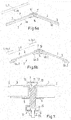
- Fig. 3 is a schematic side view of a subassembly 1 according to the invention shown in a further embodiment.
- the retaining profile elements 4a, 4b no beveled ends 15.
- the subassembly 1 comprises an element 17 for setting the desired angle ⁇ between the retaining profile elements 4a, 4b.
- the element 17 for adjusting the angle ⁇ is formed in the form of a full profile and has two contact surfaces 18 arranged at an angle to one another, on each of which a free end 15 of a retaining profile element 4a, 4b bears.
- Fig. 3 It is shown that the underside connecting element 6 has a central passage opening, through which the element 17 protrudes.
- Fig. 4 is a side view of a subassembly 1 shown, which is formed substantially semicircular.
- holding profile elements 4a, 4b, 4c, 4d, 4e, 4f, 4g, 4h are connected to each other via lower side connecting elements and upper side connecting elements, not shown, such that a polygon is formed which approximates a semicircular shape.
- photovoltaic modules 2 see, eg Fig. 1 ), which differ from the one in Fig. 4 Part arrangement shown 1 extend toward a spaced arranged further sub-assembly, which is arranged in a direction perpendicular to the plane of the illustrated sub-assembly 1 spaced.
- the two sub-assemblies are attached to each other via the photovoltaic modules 2, whereby a stable, rigid photovoltaic system is formed.
- connecting elements 19 for connecting the free ends of the end retaining profile elements 4a, 4h with a foundation, in particular the ground 20th
- Fig. 5 shows a schematic cross section through an inventive arrangement 21 for mounting. Shown are a first and a second sub-assembly 1a, 1b of the assembly 21.
- the assembly 21 may of course comprise further sub-assemblies 1.
- the sub-assemblies 1a, 1b are in large parts corresponding to the in Fig. 1 illustrated embodiment of the subassembly 1 is formed. Therefore, the corresponding statements to Fig. 1 directed.
- a retaining profile element 4a formed as a hollow body.
- a retaining profile element 4a each have two side walls 22, wherein on each side wall 22 each have a holding portion 5 is arranged to support or support a frame 3 of a photovoltaic module 2.
- the side walls 22 are connected by three connecting webs 23 each.
- a lower connecting web 23 is part of a wall which comprises the receiving groove 8 formed as a T-groove. Between the connecting webs 23 and the side walls 22 thus cavities are formed.
- an uppermost connecting web 23 is arranged at a distance from the upper end of the side walls 22, so that at the upper end a further groove of the retaining profile element 4a is formed.
- the holding profile element 4a of the first subassembly 1a is arranged at a distance A spaced from the retaining profile element 4a of the second subassembly 1b.
- the distance A can here be measured between central axes of symmetry of the holding profile elements 4a.
- a photovoltaic module 2a is arranged between the holding profile elements 4a of the first and second sub-assembly 1 a, 1 b.
- a frame 3 arranged on a left longitudinal side of the photovoltaic module 2a rests on a holding section 5 of the holding profile element 4a of the first subassembly 1.
- a arranged on a right longitudinal side of the photovoltaic module 2a frame 3 rests on a holding portion 5 of the holding profile element 4a of the second sub-assembly 1 b.
- photovoltaic module 2a is connected via top side connecting elements 7 both to the retaining profile element 4a of the first subassembly 1a and to the retaining profile element 4a of the second subassembly 1b, then a rigid, self-supporting photovoltaic system is provided.
- Fig. 6a and Fig. 6b show schematic longitudinal sections through partial arrangements 1 according to the invention in various embodiments.
- the lengths L_4a of the holding profile elements 4a, 4b are longer than a length L_3 of the sections of the frame 3 of the photovoltaic module 2 supported by the first holding profile elements 4a, 4b.
- the lengths of the retaining profile elements 4a, 4b are shorter than a length of the sections of the frame 3 of the photovoltaic module 2 held by the first retaining profile elements 4a, 4b.
- the first retaining profile elements 4a comprises two partial profile elements 4a_1, 4a_2, each of which has end sections or end face of the photovoltaic module 2 arranged portion of the frame 3.
- the further retaining profile elements 4b comprises two partial profile elements 4b_1, 4b_2, which respectively support end sections of a section of the frame 3 arranged on a longitudinal or front side of the photovoltaic module 2.
- a sum of the length L_4a_1 of a first subelement 4a_1 of the first retaining profiled element 4a and the length L_4a_2 of a second subelement 4a_2 of the first retaining profiled element 4a is shorter than the length L_3 of the portion of the frame 3 retained by the first retaining profiled element 4a.
- the arranged on the longitudinal or front side of the photovoltaic module 2 portion of the frame 3 is not along its entire length L_3 but only in the region of the ends on the support surfaces 5 formed by the bearing surfaces.
- Fig. 7 shows a cross section through a subassembly 1 according to the invention in a further embodiment.
- Fig. 7 illustrated embodiment corresponds substantially to in Fig. 1 illustrated embodiment, so that reference may be made to the corresponding statements to claim 1.
- the underside connecting element 6 is arranged on the underside 9 of the first retaining profiled element 4a outside the receiving groove 8 of the first retaining profiled element 4a.
- the receiving groove 8 is a part of a hammer head screw 24, in particular the head part arranged.
- the lower side connecting member 6 may have a through hole for the hammer head screw 24.
- a nut 25 which serves to fasten the underside connecting element 6 on the underside 9, is screwed onto the threaded portion of the hammer head screw 24.
Abstract
Die Erfindung betrifft eine Teilanordnung zur Halterung mindestens eines Photovoltaikmoduls (2), wobei die Teilanordnung (1, 1 a, 1 b) ein erstes Halteprofilelement (4a) und mindestens ein weiteres Halteprofilelement (4b, ..., 4h) umfasst, wobei die Teilanordnung (1) mindestens ein erstes Unterseitenverbindungselement (6) und mindestens ein erstes Oberseitenverbindungselement (7) umfasst, wobei das erste Unterseitenverbindungselement (6) mit Unterseiten (9) des ersten und weiteren Halteprofilelements (4a, 4b) verbunden ist, wobei das erste Oberseitenverbindungselement (7) mit Oberseiten (10) des ersten und weiteren Halteprofilelements (4a, 4b) verbunden ist, wobei das erste Oberseitenverbindungselement (7) derart ausgebildet und mit den Halteprofilelementen (4a, 4b) verbindbar ist, dass ein durch das erste Halteprofilelement (4a) halterbares Photovoltaikmodul (2) und/oder ein durch das weitere Halteprofilelement (4b) halterbares Photovoltaikmodul (2) durch das erste Oberseitenverbindungselement (7) mit dem/den Halteprofilelement/en (4a, 4b) verbindbar ist, sowie eine Anordnung (21) zur Halterung und ein Verfahren zur Herstellung einer Teilanordnung (1, 1 a, 1 b).The invention relates to a subassembly for holding at least one photovoltaic module (2), wherein the subassembly (1, 1 a, 1 b) comprises a first retaining profile element (4a) and at least one further retaining profile element (4b, ..., 4h), wherein the Partial assembly (1) comprises at least a first bottom connector (6) and at least a first top connector (7), the first bottom connector (6) being connected to bottoms (9) of the first and further support member (4a, 4b), the first top connector (7) is connected to upper sides (10) of the first and further retaining profile element (4a, 4b), wherein the first upper side connecting element (7) is formed and connectable to the retaining profile elements (4a, 4b) such that a first retaining profile element (4a ) holder photovoltaic module (2) and / or by the further holding profile element (4b) holder photovoltaic module (2) by the first Oberseitenverbindun gselement (7) with the / the holding profile element (s) (4a, 4b) is connectable, and an arrangement (21) for mounting and a method for producing a subassembly (1, 1 a, 1 b).
Description
Die Erfindung betrifft eine Teilanordnung sowie eine Anordnung zur Halterung eines Photovoltaikmoduls sowie ein Verfahren zur Herstellung einer Teilanordnung.The invention relates to a subassembly and an arrangement for mounting a photovoltaic module and to a method for producing a subassembly.
Bei der Montage von Photovoltaikmodulen auf Freiflächen werden in der Regel sogenannte Unterkonstruktionen benötigt, an der die Photovoltaikmodule in einer gewünschten Lage und mit einer gewünschten Ausrichtung montiert werden können. Für einen gewünschten Montageort müssen daher in der Regel Elemente der Unterkonstruktion eigens hergestellt oder für die Montage angepasst werden. Dies bedingt eine kosten- und zeitintensive Bereitstellung einer solchen Unterkonstruktion.When mounting photovoltaic modules on open spaces usually so-called substructures are needed to which the photovoltaic modules can be mounted in a desired location and with a desired orientation. For a desired installation site therefore usually elements of the substructure must be specially made or adapted for assembly. This requires a costly and time-consuming provision of such a substructure.
Die
Die
Die
Die
Die
Es stellt sich das technische Problem, eine Teilanordnung und eine Anordnung zur Halterung eines Photovoltaikmoduls sowie ein Verfahren zur Herstellung einer Teilanordnung zu schaffen, die eine kostengünstige und zeitlich schnelle Bereitstellung einer Tragkonstruktion für Photovoltaikmodule in einer gewünschten Lage und mit einer gewünschten Ausrichtung ermöglichen.The technical problem of providing a subassembly and an arrangement for holding a photovoltaic module and a method for producing a subassembly, which enable a cost-effective and timely provision of a support structure for photovoltaic modules in a desired position and with a desired orientation.
Die Lösung des technischen Problems ergibt sich durch die Gegenstände mit den Merkmalen der Ansprüche 1, 14 und 17. Weitere vorteilhafte Ausgestaltungen der Erfindung ergeben sich aus den Unteransprüchen.The solution of the technical problem results from the objects with the features of
Es ist eine Grundidee der Erfindung, ein modulares System zu schaffen, welches eine einfache Bereitstellung verschieden ausgebildeter Tragkonstruktionen ermöglicht, wobei gleichzeitig eine hohe Stabilität der Tragkonstruktion gewährleistet wird.It is a basic idea of the invention to provide a modular system which enables a simple provision of differently designed supporting structures, at the same time ensuring a high stability of the supporting structure.
Vorgeschlagen wird eine Teilanordnung zur Halterung mindestens eines Photovoltaikmoduls. Das Photovoltaikmodul kann auch als Solarmodul bezeichnet werden. Das Photovoltaikmodul kann insbesondere ein gerahmtes Photovoltaikmodul sein. Der Rahmen kann hierbei ein metallischer Rahmen sein, der mit einer elektrisch isolierenden Isolationsschicht, beispielsweise einer Eloxalschicht, beschichtet ist. Die Teilanordnung kann Teil einer Anordnung zur Halterung eines solchen Photovoltaikmoduls sein.Proposed is a subassembly for holding at least one photovoltaic module. The photovoltaic module can also be referred to as a solar module. The photovoltaic module may in particular be a framed photovoltaic module. The frame may in this case be a metallic frame, which is coated with an electrically insulating insulation layer, for example an anodized layer. The subassembly may be part of an arrangement for mounting such a photovoltaic module.
Die Teilanordnung umfasst ein erstes Halteprofilelement und mindestens ein weiteres Halteprofilelement. Ein Halteprofilelement bezeichnet hierbei ein Element zur Halterung des Photovoltaikmoduls. Ein solches Halteprofilelement kann insbesondere aus Metall, vorzugsweise Aluminium, ausgebildet sein. Ein Halteprofilelement kann in einem sogenannten Strangpress-Verfahren hergestellt werden. Ein Halteprofil kann hierbei ein länglich ausgebildetes Element sein, wobei ein Halteprofilelement eine vorbestimmte Länge aufweisen kann. Die Länge kann beispielsweise in einem Bereich von 500 mm bis 1500 mm liegen.The subassembly comprises a first retaining profile element and at least one further retaining profile element. A holding profile element here denotes an element for holding the photovoltaic module. Such a retaining profile element may in particular be made of metal, preferably aluminum. A holding profile element can be produced in a so-called extrusion process. A retaining profile may in this case be an elongated element, wherein a retaining profile element may have a predetermined length. The length may for example be in a range of 500 mm to 1500 mm.
Ein Halteprofilelement kann mindestens einen Halteabschnitt zur Halterung des Photovoltaikmoduls aufweisen oder ausbilden. Der Halteabschnitt kann beispielsweise als Abschnitt zur Auflage oder Anlage des Photovoltaikmoduls, insbesondere eines Randabschnittes oder eines Abschnitts des Rahmens an einer Seite des Photovoltaikmoduls, ausgebildet sein. So kann das Halteprofilelement beispielsweise eine Auflagefläche zur Auflage einer Unterseite des Randabschnittes oder eines Teils des Randabschnittes, insbesondere einer Unterseite des Rahmens, aufweisen oder ausbilden.A holding profile element can have or form at least one holding section for holding the photovoltaic module. The holding section can be designed, for example, as a section for supporting or mounting the photovoltaic module, in particular an edge section or a section of the frame on one side of the photovoltaic module. Thus, the retaining profile element, for example, a support surface for supporting a bottom of the edge portion or a portion of the edge portion, in particular a bottom of the frame, have or form.
Das Halteprofilelement kann hierbei mehrere Teilelemente umfassen, die nicht notwendigerweise verbunden sein müssen. Allerdings werden durch die Teilelemente eines Halteprofilelements jeweils Abschnitte der gleichen Seite des Photovoltaikmoduls gehaltert.The retaining profile element may in this case comprise a plurality of sub-elements, which need not necessarily be connected. However, in each case sections of the same side of the photovoltaic module are supported by the sub-elements of a holding profile element.
Das erste und das mindestens ein weitere Halteprofilelement können die gleiche Ausbildung aufweisen.The first and the at least one further retaining profile element may have the same design.
Selbstverständlich kann die Teilanordnung mehr als zwei Halteprofilelemente, beispielsweise bis zu 10 Halteprofilelemente umfassen.Of course, the subassembly may comprise more than two retaining profile elements, for example up to 10 retaining profile elements.
Erfindungsgemäß umfasst die Teilanordnung mindestens ein erstes Unterseitenverbindungselement und mindestens ein erstes Oberseitenverbindungselement. Ein Unterseitenverbindungselement kann auch als sogenannter Untergurt und ein Oberseitenverbindungselement als sogenannter Obergurt bezeichnet werden.According to the invention, the subassembly comprises at least a first underside connecting element and at least one first top side connecting element. A bottom link may also be referred to as a so-called bottom chord and a top link as a so-called top chord.
Ein Halteprofilelement kann eine Unterseite und eine Oberseite aufweisen. An oder in der Unter- bzw. Oberseite können Mittel zur Befestigung des Unterseitenverbindungselements bzw. des Oberseitenverbindungselements ausgebildet oder angeordnet sein.A retaining profile element may have a bottom and a top. On or in the lower or upper side means may be formed or arranged for fastening the lower side connecting element or the upper side connecting element.
Das Unterseitenverbindungselement ist mit Unterseiten des ersten und weiteren Halteprofilelements verbunden. Dies kann bedeuten, dass sowohl die Unterseite des ersten Halteprofilelements als auch die Unterseite des weiteren Halteprofilelements mit dem Unterseitenverbindungselement verbunden ist. Weiter kann dies bedeuten, dass das Unterseitenverbindungselement an der Unterseite des Halteprofilelements mit dem Halteprofilelement verbunden ist.The underside connecting element is connected to lower sides of the first and further retaining profile element. This can mean that both the underside of the first retaining profile element and the underside of the further retaining profile element is connected to the underside connecting element. Further, this may mean that the underside connecting element is connected to the underside of the retaining profile element with the retaining profile element.
Im Sinne dieser Erfindung kann das Merkmal "verbunden" bedeuten, dass eine kraftschlüssige, stoffschlüssige und/oder formschlüssige Verbindung vorliegt. Die Verbindung kann hierbei eine lösbare oder unlösbare Verbindung sein.For the purposes of this invention, the feature "connected" may mean that a non-positive, cohesive and / or positive connection exists. The compound may in this case be a detachable or insoluble compound.
Weiter ist das erste Oberseitenverbindungselement mit Oberseiten des ersten und weiteren Halteprofilelements verbunden. Dies kann bedeuten, dass das erste Oberseitenverbindungselement sowohl mit der Oberseite des ersten als auch mit der Oberseite des weiteren Halteprofilelements verbunden ist. Weiter kann dies bedeuten, dass das Oberseitenverbindungselement an der Oberseite des Halteprofilelements mit dem Halteprofilelement verbunden ist.Furthermore, the first upper side connecting element is connected to upper sides of the first and further retaining profile element. This may mean that the first Top link is connected to both the top of the first and with the top of the further retaining profile element. Furthermore, this may mean that the top side connection element is connected to the top side of the retaining profile element with the retaining profile element.
Das Oberseitenverbindungselement und/oder das Unterseitenverbindungselement kann/können z.B. jeweils eine oder mehrere Durchgangsöffnung(en) und/oder eine oder mehrere Gewindebohrung(en) aufweisen, die zur Verbindung des Elements mit der Oberseite bzw. Unterseite dienen.
Somit ergibt sich, dass die Halteprofilelemente über die Unterseitenverbindungselemente als auch über die Oberseitenverbindungselemente miteinander verbunden sind. Sind die Halteprofilelemente derart miteinander verbunden, so liegt ein verbundener Zustand vor.For example, the top connector and / or the bottom connector may each include one or more through holes and / or one or more threaded holes that serve to connect the member to the top and bottom, respectively.
Thus, it follows that the holding profile elements are connected to each other via the lower side connecting elements as well as via the upper side connecting elements. If the retaining profile elements are connected to one another in such a way, there is a connected state.
Hierbei ist möglich, dass keine unmittelbare Verbindung zwischen den Halteprofilelementen besteht. Allerdings ist auch nicht ausgeschlossen, dass eine solche Verbindung herstellbar ist.It is possible that there is no direct connection between the retaining profile elements. However, it is also not excluded that such a connection can be produced.
Weiter ist das erste Oberseitenverbindungselement derart ausgebildet und mit den Halteprofilelementen verbindbar, dass ein durch das erste Halteprofilelement halterbares Photovoltaikmodul und/oder ein durch das weitere Halteprofilelement halterbares Photovoltaikmodul durch das erste Oberseitenverbindungselement mit dem/den Halteprofilelement/en verbindbar ist. Insbesondere kann das erste Oberseitenverbindungselement derart ausgebildet und mit den Halteprofilelementen verbindbar sein, dass ein oder zwei Photovoltaikmodul(e) an dem ersten Halteprofilelement und/oder ein weiteres oder zwei weitere Photovoltaikmodul(e) an dem weiteren Halteprofilelement befestigt werden kann. Es ist beispielsweise vorstellbar, dass das erste Oberseitenverbindungselement Kontaktflächen zur Kontaktierung einer Oberseite eines oder zweier Photovoltaikmoduls/e, insbesondere einer Oberseite eines Randabschnittes oder Rahmens des/der Photovoltaikmoduls/e, aufweist. Weiter kann das Oberseitenverbindungselement einen Verbindungsabschnitt zur Verbindung dieser Kontaktabschnitte aufweisen. Wird das Oberseitenverbindungselement mit der Oberseite des ersten und/oder weiteren Halteprofilelements verbunden, so können die Kontaktabschnitte jeweils in Kontakt mit einem Photovoltaikmodul treten. Z.B. kann ein Photovoltaikmodul während des Verbindens des Oberseitenverbindungselements mit den Halteprofilelementen zwischen den Halteabschnitt des Halteprofilelements und den jeweiligen Kontaktabschnitt des Oberseitenverbindungselements geklemmt werden.Furthermore, the first upper-side connecting element is configured and connectable to the retaining profile elements such that a photovoltaic module which can be held by the first retaining profiled element and / or a photovoltaic module which can be retained by the further retaining profiled element can be connected to the retaining profiled element by the first upper-side connecting element. In particular, the first upper-side connection element can be designed and connectable to the retaining profile elements in such a way that one or two photovoltaic modules can be fastened to the first retaining profile element and / or another or two further photovoltaic modules can be fastened to the further retaining profile element. It is conceivable, for example, for the first upper-side connection element to have contact surfaces for contacting an upper side of one or two photovoltaic modules, in particular an upper side of an edge section or frame of the photovoltaic module (s). Further, the upper side connecting member may have a connecting portion for connecting these contact portions. If the upper side connecting element is connected to the upper side of the first and / or further holding profile element, the contact sections can each come into contact with a photovoltaic module. For example, a photovoltaic module may be connected to the substrate during connection of the top side connector Holding profile elements between the holding portion of the holding profile element and the respective contact portion of the upper side connecting element are clamped.
Somit erfolgt die Befestigung des Photovoltaikmoduls an den Halteprofilelementen zumindest teilweise mittels des Oberseitenverbindungselements.Thus, the attachment of the photovoltaic module to the retaining profile elements is at least partially by means of the upper side connecting element.
Das Oberseitenverbindungselement und das Unterseitenverbindungselement können als separate Bauteile ausgebildet sein. Durch das Vorsehen des Unterseiten- und Oberseitenverbindungselements kann in vorteilhafter Weise sowohl eine mechanische Stabilität der aus den Halteprofilelementen bestehenden Tragkonstruktion, insbesondere eine hohe Biegesteifigkeit, gewährleistet werden, während gleichzeitig eine zuverlässige Befestigung eines Photovoltaikmoduls an der Tragkonstruktion durch das Oberseitenverbindungselement ermöglicht wird.The upper side connecting element and the lower side connecting element may be formed as separate components. By providing the lower side and upper side connecting element, both a mechanical stability of the support profile elements consisting of the support profile elements, in particular a high bending stiffness, can be ensured in an advantageous manner, while at the same time enabling reliable fastening of a photovoltaic module to the support structure by the upper side connecting element.
Selbstverständlich kann die Teilanordnung mehr als ein Unterseitenverbindungselement und mehr als ein Oberseitenverbindungselement umfassen. Umfasst die Teilanordnung beispielsweise n Halteprofilelemente, so kann die Teilanordnung n-1 Unterseitenverbindungselemente und n-1 Oberseitenverbindungselemente umfassen.Of course, the subassembly may include more than one bottom link and more than one top link. If the subassembly comprises, for example, n holding profile elements, then the subassembly may comprise n-1 bottom side connecting elements and n-1 top side connecting elements.
In einer weiteren Ausführungsform sind das erste und weitere Halteprofilelement mit einem gewünschten Winkel abgewinkelt zueinander angeordnet. Diese Anordnung kann insbesondere im verbundenen Zustand gegeben sein. Der gewünschte Winkel kann einen Winkel zwischen zentralen Längsachsen der Halteprofilelemente bezeichnen. Dieser Winkel kann insbesondere größer als 0° und kleiner als 180° sein. Vorzugsweise liegt der Winkel in einem Winkelbereich von 5° bis 30°.In a further embodiment, the first and further retaining profile element are angled at a desired angle to each other. This arrangement can be given in particular in the connected state. The desired angle may designate an angle between central longitudinal axes of the retaining profile elements. This angle may in particular be greater than 0 ° and less than 180 °. Preferably, the angle is in an angular range of 5 ° to 30 °.
Hierdurch wird in vorteilhafter Weise gewährleistet, dass die an den Halteprofilelementen befestigbaren Photovoltaikmodule mit einer gewünschten Ausrichtung relativ zueinander und/oder relativ zum Erdboden montiert werden können, wenn eine die Teilanordnung zur Halterung umfassende Anordnung zur Halterung an einem Fundament, beispielsweise im Erdboden, befestigt wird.In this way, it is advantageously ensured that the photovoltaic modules which can be fastened to the retaining profile elements can be mounted with a desired orientation relative to one another and / or relative to the ground, when an assembly comprising the sub-assembly for mounting on a foundation, for example in the ground, is fastened ,
In einer weiteren Ausführungsform ist mindestens ein freies Ende des ersten und weiteren Halteprofilelements abgeschrägt. Dass Enden des ersten und weiteren Halteprofilelements abgeschrägt sind, kann bedeuten, dass endseitige Stirnflächen der Halteprofilelemente einen vorbestimmten Winkel größer als 0°, jedoch kleiner als 90° mit der zentralen Längsachse des entsprechenden Halteprofilelements einschließen. Im verbundenen Zustand können die abgeschrägten Enden der Halteprofilelemente aneinander anliegen.In a further embodiment, at least one free end of the first and further retaining profile element is chamfered. That ends of the first and further retaining profile element are chamfered, may mean that end faces of the Holding profile elements include a predetermined angle greater than 0 °, but less than 90 ° with the central longitudinal axis of the corresponding holding profile element. In the connected state, the chamfered ends of the retaining profile elements can rest against each other.
Insbesondere können freie Enden der Halteprofilelemente derart abgeschrägt sein, dass diese im verbundenen Zustand mit dem vorhergehend erläuterten gewünschten Winkel abgewinkelt zueinander angeordnet sind bzw. aneinander anliegen. Hierdurch ergibt sich in vorteilhafter Weise eine einfache Montage der Halteprofilelemente in einer abgewinkelten Anordnung.In particular, free ends of the retaining profile elements can be beveled in such a way that, in the connected state, they are angled relative to one another with the desired angle explained above or rest against one another. This results in an advantageous manner, a simple assembly of the retaining profile elements in an angled arrangement.
In einer weiteren Ausführungsform umfasst die Teilanordnung ein Element zur Einstellung des Winkels zwischen zwei Halteprofilelementen. Das Element zur Einstellung des Winkels ist zwischen freien Enden, insbesondere stirnseitigen Enden, der Halteprofilelemente angeordnet. Beispielsweise kann das Element zur Einstellung zwei Kontaktflächen aufweisen, die mit dem gewünschten Winkel abgewinkelt zueinander angeordnet sind. An diesen Kontaktflächen können jeweils stirnseitige Endflächen des ersten und weiteren Halteprofilelements anliegen. Das Element zur Einstellung des Winkels kann hierbei als Voll- oder Hohlprofil ausgebildet sein. Weiter kann das Element zur Einstellung des Winkels aus einem elektrisch leitfähigen Material, insbesondere Metall, vorzugsweise Aluminium, ausgebildet sein. Weiter beispielsweise kann das Element zur Einstellung des Winkels ein im Querschnitt dreieckförmiges oder trapezförmiges Profil aufweisen.In a further embodiment, the subassembly comprises an element for adjusting the angle between two retaining profile elements. The element for adjusting the angle is arranged between free ends, in particular front ends, of the retaining profile elements. For example, the adjustment element may have two contact surfaces which are angled at the desired angle to one another. End faces of the first and further retaining profile elements can rest against these contact surfaces. The element for adjusting the angle can be formed here as a solid or hollow profile. Further, the element for adjusting the angle of an electrically conductive material, in particular metal, preferably aluminum, may be formed. Further, for example, the element for adjusting the angle may have a triangular or trapezoidal profile in cross section.
Es ist vorstellbar, dass das Unterseitenverbindungselement und/oder das Oberseitenverbindungselement mit dem Element zur Einstellung des Winkels verbunden ist. Dies ist jedoch nicht zwingend.It is conceivable that the underside connecting element and / or the top side connecting element is connected to the element for adjusting the angle. However, this is not mandatory.
Hierdurch ergibt sich in vorteilhafter Weise, dass Halteprofilelemente ohne abgeschrägte Enden zur Herstellung einer Anordnung zur Halterung eines Photovoltaikmoduls verwendet werden können, wobei dennoch eine einfache Montage der Halteprofilelemente mit einer abgewinkelten Anordnung ermöglicht wird.This results in an advantageous manner that retaining profile elements can be used without tapered ends for the preparation of an arrangement for mounting a photovoltaic module, while still allowing easy mounting of the retaining profile elements with an angled arrangement.
Durch die Verwendung von Halteprofilelementen mit nicht abgeschrägten Enden ergibt sich in vorteilhafter Weise eine einfachere und kostengünstigere Herstellung der Halteprofilelemente, insbesondere im Rahmen eines Strangpressverfahrens mit nachfolgendem Zuschnitt, der rechtwinklig zum Halteprofilelement durchgeführt wird.Through the use of retaining profile elements with non-tapered ends results in a simpler and cheaper production of the Holding profile elements, in particular in the context of an extrusion process with subsequent cutting, which is performed at right angles to the holding profile element.
In einer weiteren Ausführungsform ist/sind das erste Unterseitenverbindungselement und/oder das erste Oberseitenverbindungselement als Winkelprofilelement ausgebildet. Beispielsweise kann ein Verbindungselement zwei Abschnitte aufweisen, wobei diese Abschnitte abgewinkelt zueinander angeordnet sind. Diese Abschnitte können insbesondere mit gewünschten Winkel abgewinkelt zueinander angeordnet sein. Weiter können diese Abschnitte die vorhergehend erläuterten Kontaktabschnitte aufweisen oder ausbilden.In a further embodiment, the first underside connecting element and / or the first top connecting element is / are formed as an angle profile element. For example, a connecting element may have two sections, wherein these sections are arranged at an angle to one another. These sections can in particular be arranged at an angle which is angled relative to one another. Further, these portions may include or form the previously explained contact portions.
Bevorzugt ist/sind das Oberseitenverbindungselement und/oder das Unterseitenverbindungselement als Blechprofil oder als Edelstahlprofil ausgebildet. Dieses Profil kann beispielsweise eine vorbestimmte Stärke, beispielsweise aus einem Bereich von 3 mm bis 8 mm, aufweisen.Preferably, the upper side connecting element and / or the lower side connecting element are / is designed as a sheet metal profile or as a stainless steel profile. This profile may for example have a predetermined thickness, for example from a range of 3 mm to 8 mm.
Hierdurch ergibt sich in vorteilhafter Weise eine zuverlässige Verbindung der Halteprofilelemente als auch eine zuverlässige Befestigung der Solarmodule.This results in an advantageous manner a reliable connection of the retaining profile elements as well as a reliable attachment of the solar modules.
In einer weiteren Ausführungsform weist das erste Oberseitenverbindungselement mindestens ein Kontaktmittel zur elektrischen Kontaktierung eines Rahmens des Photovoltaikmoduls auf oder bildet ein solches aus. Das Kontaktmittel kann insbesondere derart ausgebildet sein, dass der elektrisch leitfähige Teil des Rahmens kontaktierbar ist. Somit kann der Rahmen des Photovoltaikmoduls mit einem Potential der Teilanordnung verbunden werden. Ist die Teilanordnung mit einem Referenzpotential, beispielsweise einem Erdpotential, verbunden, so kann hierdurch eine elektrische Verbindung zwischen dem Rahmen und diesem elektrischen Referenzpotential erfolgen. Hierdurch ergibt sich in vorteilhafter Weise eine einfache Erdung der gehalterten Photovoltaikmodule.In a further embodiment, the first upper-side connecting element has at least one contact means for electrically contacting a frame of the photovoltaic module or forms such a. The contact means may in particular be designed such that the electrically conductive part of the frame is contactable. Thus, the frame of the photovoltaic module can be connected to a potential of the subassembly. If the subassembly is connected to a reference potential, for example a ground potential, an electrical connection between the frame and this electrical reference potential can thereby take place. This results in an advantageous way, a simple grounding of content-supported photovoltaic modules.
In einer weiteren Ausführungsform weist das Oberseitenverbindungselement einen Kontaktabschnitt, insbesondere eine Kontaktfläche, zur mechanischen Kontaktierung eines Rahmens des Photovoltaikmoduls auf oder bildet einen solchen aus. Das Kontaktmittel zur elektrischen Kontaktierung wird von dem Kontaktabschnitt ausgebildet oder ist an diesem angeordnet.In a further embodiment, the upper-side connecting element has or forms a contact section, in particular a contact surface, for mechanically contacting a frame of the photovoltaic module. The contact means for electrical contacting is formed by the contact portion or is arranged thereon.
Vorzugsweise kann ein Randbereich einer als Kontaktabschnitt ausgebildeten Kontaktfläche abgekantet sein. Bei der Befestigung des Oberseitenverbindungselements an einem Halteprofilelement kann die Kontaktfläche in mechanischen Kontakt mit der Oberfläche des Rahmens treten, wobei der abgekantete Randabschnitt die erläuterte Isolationsschicht durchdringt und in mechanischen als auch elektrischen Kontakt mit dem elektrisch leitfähigen Teil des Rahmens tritt.Preferably, an edge region of a contact surface designed as a contact section can be folded. When attaching the upper side connecting element to a holding profile element, the contact surface may come into mechanical contact with the surface of the frame, wherein the bent edge portion penetrates the described insulating layer and enters into mechanical as well as electrical contact with the electrically conductive part of the frame.
Selbstverständlich sind auch alternative Ausbildungen eines solchen Kontaktmittels vorstellbar, beispielsweise ein zackenförmig ausgebildeter Randbereich, ein gebogener Randbereich oder eine unebene Oberflächenstrukturierung des Oberseitenverbindungselementes, insbesondere deren Kontaktfläche. Beispielsweise kann mindestens eine pyramidenförmige oder eine spitz zulaufende Erhebungen auf der Kontaktfläche vorgesehen sein.Of course, alternative embodiments of such a contact means are conceivable, for example, a serrated edge region, a curved edge region or an uneven surface structuring of the upper side connecting element, in particular their contact surface. For example, at least one pyramidal or a pointed elevations may be provided on the contact surface.
In einer weiteren Ausführungsform bestehen die Halteprofilelemente und das Oberseitenverbindungselement aus elektrisch leitfähigem Material. Hierdurch wird in vorteilhafter Weise gewährleistet, dass der elektrisch leitfähige Teil eines Rahmens über ein Oberseitenverbindungselement und Halteprofilelement der Teilanordnung mit einem gewünschten Referenzpotential verbunden werden kann.In a further embodiment, the retaining profile elements and the upper side connecting element made of electrically conductive material. In this way, it is advantageously ensured that the electrically conductive part of a frame can be connected to a desired reference potential via a top side connecting element and retaining profile element of the subassembly.
Selbstverständlich, jedoch nicht zwingenderweise, kann auch das Unterseitenverbindungselement aus einem elektrisch leitfähigen Material ausgebildet sein.Of course, but not necessarily, the underside connector may be formed of an electrically conductive material.
In einer weiteren Ausführungsform ist die Teilanordnung elektrisch mit einem Referenzpotential, beispielsweise einem Erdpotential, verbunden. Dies kann beispielsweise über eine elektrische Verbindung eines der Halteprofilelemente und/oder eines der Oberseitenverbindungselemente und/oder eines der Unterseitenverbindungselemente mit dem Referenzpotential erfolgen. Hierdurch kann in vorteilhafter Weise die Teilanordnung geerdet werden, was eine Betriebssicherheit in vorteilhafter Weise erhöht.In a further embodiment, the subassembly is electrically connected to a reference potential, for example a ground potential. This can be done, for example, via an electrical connection of one of the retaining profile elements and / or one of the upper side connecting elements and / or one of the lower side connecting elements with the reference potential. As a result, the subassembly can be grounded in an advantageous manner, which advantageously increases operating reliability.
In einer weiteren Ausführungsform umfasst die Anordnung mindestens ein End-Unterseitenverbindungselement, wobei das End-Unterseitenverbindungselement mit einer Unterseite eines End-Halteprofilelements verbunden ist. Weiter ist das End-Unterseitenverbindungselement mit einem Fundament verbunden.In a further embodiment, the arrangement comprises at least one end bottom side connecting element, wherein the end bottom side connecting element with a Bottom of an end retaining profile element is connected. Further, the end bottom link is connected to a foundation.
Ein End-Halteprofilelement kann hierbei ein Halteprofilelement der Teilanordnung bezeichnen, welches ein Ende aufweist, welches nicht über ein Unterseitenverbindungselement und/oder ein Oberseitenverbindungselement mit einem weiteren Halteprofilelement verbunden ist. Dieses kann somit in vorteilhafter Weise über das End-Unterseitenverbindungselement mit einem Fundament oder einer weiteren Tragstruktur verbunden werden. Das End-Unterseitenverbindungselement kann hierbei wie ein Unterseitenverbindungselement ausgebildet sein. In diesem Fall kann die Teilanordnung neben einem oder mehreren Unterseitenverbindungselementen auch noch ein oder zwei End-Unterseitenverbindungselemente umfassen.An end retaining profile element may in this case designate a retaining profile element of the subassembly which has one end which is not connected to a further retaining profile element via a bottom side connecting element and / or a top side connecting element. This can thus be connected in an advantageous manner via the end bottom side connecting element with a foundation or another support structure. The end underside connecting element may in this case be designed like a lower side connecting element. In this case, the subassembly may also include one or more end bottom connection elements in addition to one or more bottom side connection elements.
Selbstverständlich ist es auch vorstellbar, die Verwendung mit einem Fundament über ein End-Oberseitenverbindungselement vorzunehmen.Of course, it is also conceivable to make use of a foundation via an end top connector.
Alternativ sind selbstverständlich andere Ausführungsformen zur Befestigung der Teilanordnung an dem Fundament vorstellbar. Beispielsweise kann ein Gründungselement, beispielsweise eine Gründungsplatte, an einem freien Ende eines End-Halteprofilelements befestigt werden.Alternatively, of course, other embodiments for attaching the subassembly to the foundation are conceivable. For example, a foundation member, such as a foundation plate, may be attached to a free end of an end retaining profile member.
In einer weiteren Ausführungsform sind Halteprofilelemente der Teilanordnung derart ausgebildet und angeordnet, dass die Halteprofilelemente eine im Wesentlichen bogenförmige, insbesondere halbkreisförmige, Teilanordnung zur Halterung ausbilden. Dass die Halteprofilelemente der Teilanordnung derart ausgebildet und angeordnet sind, kann bedeuten, dass die Teilanordnung eine vorbestimmte Anzahl von Halteprofilelementen einer vorbestimmten Länge umfasst, die jeweils mit einem gewünschten Winkel abgewinkelt zueinander angeordnet sind, um die im Wesentlichen bogenförmige Teilanordnung bereitzustellen.In a further embodiment, retaining profile elements of the subassembly are designed and arranged such that the retaining profile elements form a substantially arcuate, in particular semicircular, subassembly for mounting. The fact that the retaining profile elements of the subassembly are designed and arranged in such a way may mean that the subassembly comprises a predetermined number of retaining profile elements of a predetermined length, which are each angled at a desired angle to each other to provide the substantially arcuate subassembly.
Hierbei bezeichnet eine im Wesentlichen bogenförmige Teilanordnung eine vieleckförmige Struktur, insbesondere ein Polygon. Ein solches Polygon kann gleichseitig oder gleichwinklig sein. Durch die in einer solchen vieleckförmigen Struktur aneinander angeordneten Halteprofilelemente wird die ideale Bogen- oder Kreisform angenähert, jedoch nicht erreicht.Here, a substantially arcuate subassembly denotes a polygonal structure, in particular a polygon. Such a polygon may be equilateral or equiangular. By arranged in such a polygonal structure adjacent holding profile elements, the ideal arc or circular shape is approached, but not achieved.
Hierdurch ergibt sich in vorteilhafter Weise, dass Photovoltaikmodule mit unterschiedlicher Neigung und somit Ausrichtung montiert werden können. Insbesondere ermöglicht die Teilanordnung die Herstellung eines Photovoltaiksystems, welches eine im Vergleich mit dachmontierten Photovoltaiksystemen eine flache Tagesganglinie, jedoch keine steile Peak-Ertragskurve aufweist.This results in an advantageous manner that photovoltaic modules with different inclination and thus alignment can be mounted. In particular, the subassembly makes it possible to produce a photovoltaic system which has a flat diurnal line compared to roof mounted photovoltaic systems but no steep peak yield curve.
In einer weiteren Ausführungsform ist eine Länge eines Halteprofilelements größer als die Länge der durch das Halteprofilelement gehalterten Seite des Photovoltaikmoduls oder gleich dieser Länge. Die gehalterte Seite kann eine Längsseite oder Stirnseite des Photovoltaikmoduls sein.In a further embodiment, a length of a retaining profile element is greater than the length of the side of the photovoltaic module supported by the retaining profile element or equal to this length. The supported side may be a longitudinal side or front side of the photovoltaic module.
Gehaltert kann bedeuten, dass die Seite oder ein an der Seite angeordneter Rahmen bzw. Abschnitt des Rahmens in, an oder auf dem erläuterten Halteabschnitt des Halteprofilelements angeordnet ist.Feeder may mean that the side or a frame or section of the frame arranged on the side is arranged in, on or on the explained holding section of the holding profile element.
In dem Fall, dass die Länge des Halteprofilelements größer als die oder gleich der Länge der durch das Halteprofilelement gehalterten Seite des Photovoltaikmoduls ist, kann die Seite oder der an der Seite angeordnete Rahmen bzw. Abschnitt des Rahmens entlang seiner gesamten Länge in, an oder auf dem erläuterten Halteabschnitt des Halteprofilelements angeordnet sein. In diesem Fall kann die Stabilität der resultierenden Anordnung durch das Halteprofilelement verbessert werden.In the event that the length of the retaining profile element is greater than or equal to the length of the side of the photovoltaic module supported by the retaining profile element, the side or side frame or section of the frame may be in, on or on along its entire length be arranged the explained holding portion of the holding profile element. In this case, the stability of the resulting assembly can be improved by the holding profile element.
Alternativ ist die Länge eines Halteprofilelements kleiner als die Länge der durch das Halteprofilelement gehalterten Seite des Photovoltaikmoduls. In diesem Fall kann die Seite oder der an der Seite angeordnete Rahmen bzw. Abschnitt des Rahmens nicht entlang seiner gesamten Länge in, an oder auf dem erläuterten Halteabschnitt des Halteprofilelements angeordnet sein. In diesem Fall kann die Stabilität der resultierenden Anordnung durch den Rahmen gewährleistet werden.Alternatively, the length of a retaining profile element is smaller than the length of the content held by the retaining profile element side of the photovoltaic module. In this case, the side or the frame or portion of the frame arranged on the side can not be arranged along its entire length in, on or on the explained holding section of the holding profile element. In this case, the stability of the resulting assembly can be ensured by the frame.
Umfasst das Halteprofilelement mehrere Teilelemente, so kann die Länge jedes Teilelements oder die Summe der Längen aller Teilelemente kleiner als die Länge der durch das Halteprofilelement gehalterten Seite des Photovoltaikmoduls sein.If the retaining profile element comprises a plurality of sub-elements, then the length of each sub-element or the sum of the lengths of all sub-elements may be smaller than the length of the side of the photovoltaic module supported by the retaining profile element.
In einer weiteren Ausführungsform weist ein Halteprofilelement an der Unterseite eine Aufnahmenut auf, wobei das Unterseitenverbindungselement in oder außerhalb der Aufnahmenut angeordnet ist.In a further embodiment, a retaining profile element has a receiving groove on the underside, wherein the underside connecting element is arranged in or outside the receiving groove.
Weiter vorgeschlagen wird eine Anordnung zur Halterung mindestens eines Photovoltaikmoduls. Die Anordnung umfasst hierbei mindestens zwei Teilanordnungen gemäß einer der in dieser Erfindung beschriebenen Ausführungsformen.Further proposed is an arrangement for holding at least one photovoltaic module. The arrangement here comprises at least two subassemblies according to one of the embodiments described in this invention.
Weiter ist die erste Teilanordnung beabstandet zu einer zweiten Teilanordnung angeordnet. Der Abstand kann an eine Länge oder Breite eines Photovoltaikmoduls angepasst sein. Zwischen den Teilanordnungen können Photovoltaikmodule angeordnet werden. Ein Photovoltaikmodul, insbesondere ein erster Randabschnitt, vorzugsweise ein erster Abschnitt des Rahmens, kann an einem Halteprofilelement der ersten Teilanordnung angeordnet und mittels eines Oberseitenverbindungselements der ersten Teilanordnung an diesem Halteprofilelement befestigt werden. Weiter kann dieses Photovoltaikmodul, insbesondere ein weiterer Randabschnitt, vorzugsweise ein weiterer Abschnitt des Rahmens, an einem Halteprofilelement der zweiten Teilanordnung angeordnet werden und mit diesem Halteprofilelement über das Oberseitenverbindungselement der zweiten Teilanordnung verbunden werden. Die an den Halteprofilelementen angeordneten Abschnitte des Solarmoduls können insbesondere Abschnitte von gegenüberliegenden Längs- oder Querseiten des Solarmoduls sein. Selbstverständlich kann die Anordnung zur Halterung mehr als zwei Teilanordnungen umfassen.Furthermore, the first subassembly is arranged at a distance from a second subassembly. The distance can be adapted to a length or width of a photovoltaic module. Between the sub-assemblies photovoltaic modules can be arranged. A photovoltaic module, in particular a first edge section, preferably a first section of the frame, can be arranged on a retaining profile element of the first subassembly and fastened to this retaining profile element by means of a top side connecting element of the first subassembly. Furthermore, this photovoltaic module, in particular a further edge section, preferably a further section of the frame, can be arranged on a retaining profile element of the second subassembly and connected to this retaining profile element via the upper side connecting element of the second subassembly. The arranged on the holding profile elements sections of the solar module may in particular be sections of opposite longitudinal or transverse sides of the solar module. Of course, the arrangement may include more than two sub-assemblies for mounting.
Hierdurch ergibt sich in vorteilhafter Weise eine stabile Anordnung zur Halterung von Photovoltaikmodulen, bei der die mechanische Stabilität durch Integration des Photovoltaikmoduls, insbesondere dessen Rahmens, in die Montagekonstruktion gewährleistet wird. Weiter wird ein Montageaufwand deutlich verringert. Die Teilanordnungen sowie das montierte Photovoltaikmodul bilden in vorteilhafter Weise ein selbst aussteifendes, statisch tragendes System.This results in an advantageous manner a stable arrangement for mounting photovoltaic modules, in which the mechanical stability is ensured by integration of the photovoltaic module, in particular its frame in the mounting structure. Furthermore, an assembly effort is significantly reduced. The subassemblies and the mounted photovoltaic module advantageously form a self-stiffening, statically supporting system.
Hierbei können die verschiedenen Teilanordnungen ausschließlich über das zwischen den Teilanordnungen angeordnete Photovoltaikmodul verbunden sein.Here, the various sub-assemblies can be connected exclusively via the arranged between the sub-assemblies photovoltaic module.
In einer weiteren Ausführungsform bildet mindestens ein Unterseitenverbindungselement der ersten Teilanordnung ein Unterseitenverbindungselement der zweiten Teilanordnung. Alternativ oder kumulativ bildet mindestens ein Oberseitenverbindungelement der ersten Teilanordnung ein Oberseitenverbindungselement der zweiten Teilanordnung. Vorstellbar ist z.B., dass ein oder mehrere, jedoch nicht alle, Unterseiten- und/oder Oberseitenverbindungselement(e) sowohl ein Verbindungselement der ersten als auch der weiteren Teilanordnung bildet. Hierbei kann ein solches Verbindungselement sich von der ersten Teilanordnung zur zweiten Teilanordnung erstrecken. Hierdurch wird in vorteilhafter Weise eine mechanische Stabilität der Anordnung erhöht und eine Montage vereinfacht. Selbstverständlich kann ein solches Verbindungselement auch ein Verbindungselement von mehr als zwei Teilanordnungen sein.In a further embodiment, at least one underside connecting element of the first subassembly forms a underside connecting element of the second subassembly. Alternatively or cumulatively, at least one upper-side connecting element of the first sub-assembly forms a top-side connecting element of the second sub-assembly. It is conceivable, for example, that one or more, but not all, bottom and / or top connecting members form both a connecting element of the first and the further subassembly. In this case, such a connecting element can extend from the first subassembly to the second subassembly. As a result, a mechanical stability of the arrangement is advantageously increased and simplifies installation. Of course, such a connecting element may also be a connecting element of more than two subassemblies.
In einer weiteren Ausführungsform wird mindestens ein Photovoltaikmodul von einem Halteprofilelement der ersten Teilanordnung und einem Halteprofilelement der zweiten Teilanordnung gehaltert. Insbesondere kann das mindestens eine Photovoltaikmodul über ein Oberseitenverbindungselement an den entsprechenden Halteprofilelementen befestigt oder mit diesen mechanisch verbunden werden. Eine derartige Anordnung kann auch als Photovoltaiksystem bezeichnet werden.In a further embodiment, at least one photovoltaic module is supported by a holding profile element of the first subassembly and a holding profile element of the second subassembly. In particular, the at least one photovoltaic module can be fastened to the corresponding retaining profile elements via a top-side connecting element or can be mechanically connected thereto. Such an arrangement may also be referred to as a photovoltaic system.
Weiter vorgeschlagen wird ein Verfahren zur Montage einer Teilanordnung zur Halterung mindestens eines Photovoltaikmoduls. Das Verfahren dient hierbei zur Herstellung einer Teilanordnung gemäß einer der in dieser Erfindung beschriebenen Ausführungsformen. Somit kann dieses Verfahren alle hierzu notwendigen Verfahrensschritte umfassen.Further proposed is a method for mounting a subassembly for holding at least one photovoltaic module. The method serves to produce a subassembly according to one of the embodiments described in this invention. Thus, this method may include all necessary process steps.
Insbesondere werden ein erstes Halteprofilelement, mindestens ein weiteres Halteprofilelement, mindestens ein erstes Unterseitenverbindungselement und mindestens ein Oberseitenverbindungselement bereitgestellt. Das erste Unterseitenverbindungselement wird mit Unterseiten des ersten und weiteren Halteprofilelements verbunden. Weiter wird das erste Oberseitenverbindungselement mit Oberseiten des ersten und weiteren Halteprofilelements verbunden.In particular, a first retaining profile element, at least one further retaining profile element, at least one first lower side connecting element and at least one upper side connecting element are provided. The first underside connector is connected to bottoms of the first and further bracket members. Furthermore, the first upper side connecting element is connected to upper sides of the first and further retaining profiled element.
Hierdurch ergibt sich in vorteilhafter Weise eine einfache Montage einer biegesteifen Tragkonstruktion für Photovoltaikmodule. Durch die Verbindung über die Unterseitenverbindungselemente und/oder Oberseitenverbindungselemente wird eine biegesteife Teilanordnung bereitgestellt.This results in an advantageous manner a simple installation of a rigid support structure for photovoltaic modules. Through the connection via the underside connecting elements and / or top side connecting elements, a rigid subassembly is provided.
In einer weiteren Ausführungsform wird vor der Verbindung des Oberseitenverbindungselements mit den Oberseiten des ersten und weiteren Halteprofilelements jeweils mindestens ein Photovoltaikmodul an den Halteprofilelementen angeordnet. Vorstellbar ist, dass zwei Photovoltaikmodule an einem Halteprofilelement angeordnet werden. Beispielsweise kann mindestens ein Photovoltaikmodul, insbesondere ein Randabschnitt, vorzugsweise ein Abschnitt des Rahmens, auf oder an oder in entsprechenden Halteabschnitten eines der Halteprofilelemente angeordnet werden. Dann werden durch die Verbindung des Oberseitenverbindungselements mit den Oberseiten der Halteprofilelemente die Photovoltaikmodule mit den Halteprofilelementen verbunden. Hierdurch kann das Photovoltaikmodul eingespannt werden. Insbesondere können verschiedene Abschnitte eines Photovoltaikmoduls, insbesondere verschiedene Randabschnitte, vorzugsweise verschiedene Abschnitte des Rahmens, mit Halteprofilelementen verschiedener Teilanordnungen verbunden werden, wodurch ein biegesteifes, selbsttragendes und statisch tragfähiges Photovoltaiksystem bereitgestellt wird.In a further embodiment, in each case at least one photovoltaic module is arranged on the retaining profile elements before the connection of the upper side connecting element with the upper sides of the first and further retaining profile element. It is conceivable that two photovoltaic modules are arranged on a holding profile element. For example, at least one photovoltaic module, in particular an edge section, preferably a section of the frame, can be arranged on or at corresponding holding sections of one of the retaining profile elements. Then the photovoltaic modules are connected to the holding profile elements by the connection of the upper side connecting element with the upper sides of the retaining profile elements. This allows the photovoltaic module to be clamped. In particular, different sections of a photovoltaic module, in particular different edge sections, preferably different sections of the frame, can be connected to holding profile elements of different subassemblies, whereby a rigid, self-supporting and statically stable photovoltaic system is provided.
In einer weiteren Ausführungsform wird durch die Verbindung des Oberseitenverbindungselements mit den Oberseiten der Halteprofilelemente ein Rahmen mindestens eines Photovoltaikmoduls elektrisch kontaktiert. Dies kann beispielsweise durch die erläuterte Abkantung eines Randabschnitts einer Kontaktfläche des Oberseitenverbindungselements erfolgen.In a further embodiment, a frame of at least one photovoltaic module is electrically contacted by the connection of the upper side connecting element with the upper sides of the retaining profile elements. This can be done, for example, by the explained fold of a marginal portion of a contact surface of the upper side connecting element.
Zusammenfassend ergibt sich ein minimalistisches, statisch tragendes, baukastenartig aufbaubares und somit erweiterbares System zur Halterung von Photovoltaikmodulen. In diesem System können Rahmen der Module mit einem gemeinsamen Referenzpotential, vorzugsweise einem Erdpotential, verbunden sein. Weiter kann eine Kraftableitung von auf die Photovoltaikmodule wirkenden Zug- oder Druckkräften über die Oberseitenverbindungselemente und Unterseitenverbindungselemente in die Halteprofilelemente erfolgen, die dann diese Kräfte wiederum in ein Fundament ableiten können.In summary, this results in a minimalist, static-bearing, modular buildable and thus expandable system for mounting photovoltaic modules. In this system, frames of the modules may be connected to a common reference potential, preferably a ground potential. Furthermore, a force dissipation of tensile or compressive forces acting on the photovoltaic modules can take place via the upper-side connecting elements and lower-side connecting elements in the retaining profile elements, which in turn can then divert these forces into a foundation.
Die vorgeschlagene Teilanordnung und Anordnung zur Halterung eines Photovoltaikmoduls kann insbesondere zur Herstellung von kleineren Solaranlagen mit flacher Tagesgangertragskurve dienen.The proposed sub-assembly and arrangement for mounting a photovoltaic module can be used in particular for the production of smaller solar systems with a flat daily output yield curve.
Vorzugsweise ist das Oberseitenverbindungselement und/oder das Unterseitenverbindungselement ein Edelstahlblech. Dieses ist materialfest, bietet einen hohen Korrosionsschutz und eine hohe elektrische Leitfähigkeit.Preferably, the top-side connector and / or the bottom-side connector is a stainless steel sheet. This is resistant to material, offers high corrosion protection and high electrical conductivity.
Die vorgeschlagenen Ausführungsformen ermöglichen in vorteilhafter Weise eine Herstellung einer Tragkonstruktion, die für verschiedene Anwendungsfälle variiert und auf diese angepasst werden kann. Durch die modulare Erweiterbarkeit ist eine hohe Flexibilität bei der Montage gegeben. Gleichzeitig können Herstellungskosten durch die Verwendung standardisierter Bauteile reduziert werden.The proposed embodiments advantageously make it possible to produce a supporting structure which can be varied and adapted to different applications. Due to the modular extensibility, a high degree of flexibility in assembly is given. At the same time, manufacturing costs can be reduced by using standardized components.
Die vorgeschlagene Teilanordnung und Anordnung ermöglicht auch in vorteilhafter Weise die Verwendung von Photovoltaikmodulen mit einem hohen Modulgewicht, da derartige Photovoltaikmodule bei der vorgeschlagenen Anordnung eine hohe mechanische Last-und Schwingungsstabilität bereitstellen. Auch können Photovoltaikmodule mit einer im Vergleich hohen Modulausgangsspannung verwendet werden, da hierdurch in vorteilhafter Weise die vorhergehend erläuterten kleinen Photovoltaikanlagen mit einer gewünschten Ausgangsleistung hergestellt werden können.The proposed subassembly and arrangement also advantageously allows the use of high module weight photovoltaic modules because such photovoltaic modules provide high mechanical load and vibration stability in the proposed arrangement. Also photovoltaic modules can be used with a comparatively high module output voltage, as this can be advantageously produced with a desired output power, the previously explained small photovoltaic systems.
Die vorgeschlagene Teilanordnung und Anordnung zur Halterung kann als raumumschließende Anordnung für andere Zwecke, wie beispielsweise zur Herstellung eines Carports, eines Stalls oder eines Lagerraumes dienen.The proposed subassembly and arrangement for mounting can serve as raumumschließende arrangement for other purposes, such as for the production of a carport, a stable or a storage room.
Beschrieben werden auch die einzelnen Bestandteile einer Teilanordnung, insbesondere ein Halteprofilelement, ein Oberseitenverbindungselement und ein Unterseitenverbindungselement, wobei diese Bestandteile derart ausgebildet sind, dass eine Teilanordnung oder eine Anordnung zur Halterung gemäß einer der in dieser Erfindung beschriebenen Ausführungsformen herstellbar ist.Also described are the individual components of a subassembly, in particular a holding profile element, a top side connecting element and a bottom side connecting element, wherein these components are designed such that a subassembly or an arrangement for mounting according to one of the embodiments described in this invention can be produced.
Beschrieben wird auch ein Verfahren zur Herstellung eines Photovoltaiksystems, wobei mindesten zwei Teilanordnungen gemäß einer der in dieser Erfindung beschriebenen Ausführungsformen bereitgestellt und beabstandet zueinander angeordnet werden. Weiter wird ein Photovoltaikmodul an einem Halteprofilelement einer ersten Teilanordnung und an einem Halteprofilelement einer zweiten Teilanordnung, insbesondere an oder auf deren Halteabschnitten, angeordnet. Beispielsweise kann ein erster Randabschnitt oder ein Rahmen im Bereich des ersten Randabschnitts an dem Halteprofilelement der ersten Teilanordnung und ein weiterer Randabschnitt oder Rahmen im Bereich des weiteren Randabschnitts, an dem Halteprofilelement der zweiten Teilanordnung angeordnet werden. Der erste und weitere Randabschnitt können an gegenüberliegenden Seiten des Photovoltaikmoduls angeordnet sein. Dann kann ein erstes Oberseitenverbindungselement mit der Oberseite des Halteprofilelements der ersten Teilanordnung und das erste oder vorzugweise ein weiteres Oberseitenverbindungselement mit der Oberseite des Halteprofilelement der zweiten Teilanordnung verbunden werden, wobei durch die Verbindung der Oberseitenverbindungselemente mit den jeweiligen Oberseiten der Halteprofilelemente das Photovoltaikmodul mit den Halteprofilelementen verbunden wird.Also described is a method of making a photovoltaic system, wherein at least two sub-arrays are provided according to one of the embodiments described in this invention and spaced from one another. Furthermore, a photovoltaic module is arranged on a retaining profile element of a first subassembly and on a retaining profile element of a second subassembly, in particular on or on its retaining sections. For example, a first edge portion or a frame in the region of the first edge portion on the retaining profile element of the first subassembly and a further edge portion or frame in the region of the further edge portion are arranged on the retaining profile element of the second subassembly. The first and further edge portions may be disposed on opposite sides of the photovoltaic module. Then, a first upper side connecting element with the upper side of the retaining profile element of the first subassembly and the first or preferably another upper side connecting element can be connected to the upper side of the retaining profile element of the second subassembly, the photovoltaic module being connected to the retaining profile elements by the connection of the upper side connecting elements to the respective upper sides of the retaining profile elements becomes.
Die Erfindung wird anhand eines Ausführungsbeispiels näher erläutert. Die Figuren zeigen:
- Fig. 1
- einen schematischen Querschnitt durch eine erfindungsgemäße Teilanordnung,
- Fig. 2
- eine schematische Seitenansicht einer erfindungsgemäßen Teilanordnung in einer weiteren Ausführungsform,
- Fig. 3
- eine schematische Seitenansicht einer erfindungsgemäßen Teilanordnung in einer weiteren Ausführungsform,
- Fig. 4
- eine schematische Seitenansicht einer erfindungsgemäßen Teilanordnung,
- Fig. 5
- einen schematischen Querschnitt durch eine erfindungsgemäße Anordnung zur Halterung,
- Fig. 6a
- einen schematischen Längsschnitt durch eine erfindungsgemäße Teilanordnung in einer weiteren Ausführungsform,
- Fig. 6b
- einen schematischen Längsschnitt durch eine erfindungsgemäße Teilanordnung in einer weiteren Ausführungsform und
- Fig. 7
- einen schematischen Querschnitt durch eine erfindungsgemäße Teilanordnung in einer weiteren Ausführungsform.
- Fig. 1
- a schematic cross section through a subassembly according to the invention,
- Fig. 2
- a schematic side view of a subassembly according to the invention in a further embodiment,
- Fig. 3
- a schematic side view of a subassembly according to the invention in a further embodiment,
- Fig. 4
- a schematic side view of a subassembly according to the invention,
- Fig. 5
- a schematic cross section through an inventive arrangement for mounting,
- Fig. 6a
- a schematic longitudinal section through a subassembly according to the invention in a further embodiment,
- Fig. 6b
- a schematic longitudinal section through a partial arrangement according to the invention in a further embodiment and
- Fig. 7
- a schematic cross section through a subassembly according to the invention in a further embodiment.
Die Teilanordnung 1 umfasst ein erstes Halteprofilelement 4a. Dieses bildet Halteabschnitte 5 zur Halterung der Photovoltaikmodule 2 aus. Die Halteabschnitte 5 sind insbesondere als abkragende Stege ausgebildet, die eine Auflagefläche für die Rahmen 3 der Photovoltaikmodule 2 aufweisen. In
Weiter umfasst die Teilanordnung 1 ein Unterseitenverbindungselement 6 sowie ein Oberseitenverbindungselement 7.Furthermore, the subassembly 1 comprises a bottom
Das Unterseitenverbindungselement 6 ist in einer Aufnahmenut 8 des ersten Halteprofilelements 4a angeordnet, die an einer Unterseite 9 des ersten Halteprofilelements 4a von diesem ausgebildet wird. Die Aufnahmenut 8 kann hierbei als so genannte T-Nut ausgebildet sein. Durch die Aufnahme in diese Nut 8 ist das Unterseitenverbindungselement 6 mit der Unterseite 9 des ersten Halteprofilelements 4a verbunden. Nicht in
Weiter dargestellt ist ein Oberseitenverbindungselement 7, welches in
Die Teilanordnung 1 umfasst ein Unterseitenverbindungselement 6, welches als Winkelblech ausgebildet ist. Das Winkelblech umfasst zwei Schenkel, die mit einem gewünschten Winkel α abgewinkelt zueinander angeordnet sind. Das Unterseitenverbindungselement 6 ist über schematisch dargestellte Schrauben 14 an den Unterseiten 9 der Halteprofilelemente 4a, 4b mit diesen verbunden. Hierbei ist ein erster Schenkel des Unterseitenverbindungselements 6 mit der Unterseite 9 des ersten Halteprofilelements 4a verbunden und der zweite Schenkel mit der Unterseite des weiteren Halteprofilelements 4b.The subassembly 1 comprises a bottom
In
Weiter dargestellt ist ein Oberseitenverbindungselement 7, welches ebenfalls über schematisch dargestellte Schrauben 16 mit Oberseiten 10 der Halteprofilelemente 4a, 4b verbunden ist. Auch das Oberseitenverbindungselement 7 ist als Winkelblech ausgebildet, welches zwei mit dem gewünschten Winkel α zueinander abgewinkelte Schenkel aufweist. Ein erster Schenkel ist hierbei mit der Oberseite 10 des ersten Halteprofilelements 4a und der weitere Schenkel mit der Oberseite 10 des weiteren Halteprofilelements 4b verbunden.Also shown is a top connecting
In
In
In
Die Teilanordnungen 1a, 1 b sind in großen Teilen entsprechend der in
Im Unterschied zur der in
Weiter ist dargestellt, dass das Halteprofilelement 4a der ersten Teilanordnung 1 a mit einem Abstand A beabstandet von dem Halteprofilelement 4a der zweiten Teilanordnung 1 b angeordnet ist. Der Abstand A kann hierbei zwischen zentralen Symmetrieachsen der Halteprofilelemente 4a gemessen werden.It is further shown that the holding profile element 4a of the first subassembly 1a is arranged at a distance A spaced from the retaining profile element 4a of the second subassembly 1b. The distance A can here be measured between central axes of symmetry of the holding profile elements 4a.
Zwischen den Halteprofilelementen 4a der ersten und zweiten Teilanordnung 1 a, 1 b ist ein Photovoltaikmodul 2a angeordnet. Hierbei liegt ein an einer linken Längsseite des Photovoltaikmoduls 2a angeordneter Rahmen 3 auf einem Halteabschnitt 5 des Halteprofilelements 4a der ersten Teilanordnung 1 auf. Ein an einer rechten Längsseite des Photovoltaikmoduls 2a angeordneter Rahmen 3 liegt auf einem Halteabschnitt 5 des Halteprofilelements 4a der zweiten Teilanordnung 1 b auf.Between the holding profile elements 4a of the first and second sub-assembly 1 a, 1 b, a photovoltaic module 2a is arranged. In this case, a
Ist das Photovoltaikmodul 2a über Oberseitenverbindungselemente 7 sowohl mit dem Halteprofilelement 4a der ersten Teilanordnung 1a als auch mit dem Halteprofilelement 4a der zweiten Teilanordnung 1 b verbunden, so wird ein biegesteifes, selbsttragendes Photovoltaiksystem bereitgestellt.If the photovoltaic module 2a is connected via top
In
In
Z.B. ist eine Länge L_4a_1 eines ersten Teilelements 4a_1 des ersten Halteprofilelements 4a und eine Länge L_4a_2 eines zweiten Teilelements 4a_2 des ersten Halteprofilelements 4a und somit auch eine Länge der jeweiligen Halteabschnitte 5 (siehe z.B.
Somit liegt der an der Längs- oder Stirnseite des Photovoltaikmoduls 2 angeordnete Abschnitt des Rahmens 3 nicht entlang seiner gesamten Länge L_3 sondern nur im Bereich der Enden auf der von den Halteabschnitten 5 ausgebildeten Auflageflächen auf.Thus, the arranged on the longitudinal or front side of the
Im Unterschied zu der in
- 11
- Teilanordnungsubassembly
- 2, 2a2, 2a
- Photovoltaikmodulphotovoltaic module
- 33
- Rahmenframe
- 4a, ... 4h4a, ... 4h
- HalteprofilelementeRetaining profile elements
- 4a_1, 4a_24a_1, 4a_2
- Teilelemente eines HalteprofilelementsPartial elements of a retaining profile element
- 4b_1, 4b_24b_1, 4b_2
- Teilelemente eines HalteprofilelementsPartial elements of a retaining profile element
- 55
- Halteabschnitteholding portions
- 66
- UnterseitenverbindungselementLower side connecting element
- 77
- OberseitenverbindungselementTop fastener
- 88th
- Aufnahmenutreceiving groove
- 99
- Unterseitebottom
- 1010
- Oberseitetop
- 1111
- DurchgangsöffnungThrough opening
- 1212
- Kontaktflächecontact area
- 1313
- Kanteedge
- 1414
- Schraubescrew
- 1515
- freies Endefree end
- 1616
- Schraubescrew
- 1717
- Element zur Einstellung eines WinkelsElement for adjusting an angle
- 1818
- Kontaktflächecontact area
- 1919
- Verbindungselementconnecting element
- 2020
- Erdbodenground
- 2121
- Anordnung zur HalterungArrangement for mounting
- 2222
- SeitenwandSide wall
- 2323
- Verbindungsstegconnecting web
- 2424
- HammerkopfschraubeT-head bolt
- 2525
- Muttermother
- AA
- Abstanddistance
- L_3L_3
- Länge eines Abschnitts des RahmensLength of a section of the frame
- L_4aL_4a
- Länge eines HalteprofilelementsLength of a holding profile element
- L_4a_1L_4a_1
- Länge eines ersten Teilelements eines HalteprofilelementsLength of a first sub-element of a retaining profile element
- L_4a_2L_4a_2
- Länge eines zweiten Teilelements eines HalteprofilelementsLength of a second sub-element of a retaining profile element
Claims (19)
wobei die Teilanordnung (1, 1a, 1 b) ein erstes Halteprofilelement (4a) und mindestens ein weiteres Halteprofilelement (4b, ..., 4h) umfasst,
dadurch gekennzeichnet, dass
die Teilanordnung (1, 1a, 1b) mindestens ein erstes Unterseitenverbindungselement (6) und mindestens ein erstes Oberseitenverbindungselement (7) umfasst, wobei das erste Unterseitenverbindungselement (6) mit Unterseiten (9) des ersten und weiteren Halteprofilelements (4a, 4b) verbunden ist, wobei das erste Oberseitenverbindungselement (7) mit Oberseiten (10) des ersten und weiteren Halteprofilelements (4a, 4b) verbunden ist, wobei das erste Oberseitenverbindungselement (7) derart ausgebildet und mit den Halteprofilelementen (4a, 4b) verbindbar ist, dass ein durch das erste Halteprofilelement (4a) halterbares Photovoltaikmodul (2) und/oder ein durch das weitere Halteprofilelement (4b) halterbares Photovoltaikmodul (2) durch das erste Oberseitenverbindungselement (7) mit dem/den Halteprofilelement/en (4a, 4b) verbindbar ist.Subassembly for holding at least one photovoltaic module (2),
wherein the subassembly (1, 1a, 1b) comprises a first retaining profile element (4a) and at least one further retaining profile element (4b, ..., 4h),
characterized in that
the subassembly (1, 1a, 1b) comprises at least a first underside connecting element (6) and at least one first top connecting element (7), wherein the first underside connecting element (6) is connected to lower sides (9) of the first and further holding profiled element (4a, 4b) wherein the first upper side connecting member (7) is connected to upper sides (10) of the first and further holding profile members (4a, 4b), the first upper side connecting member (7) being formed and connectable with the holding profile members (4a, 4b) the first retaining profile element (4a) holder photovoltaic module (2) and / or one by the further retaining profile element (4b) holder photovoltaic module (2) by the first top side connecting element (7) with the / the holding profile element (s) (4a, 4b) is connectable.
Applications Claiming Priority (1)
| Application Number | Priority Date | Filing Date | Title |
|---|---|---|---|
| DE102015206062.4A DE102015206062A1 (en) | 2015-04-02 | 2015-04-02 | Subassembly and arrangement for mounting at least one photovoltaic module and method for producing a subassembly |
Publications (1)
| Publication Number | Publication Date |
|---|---|
| EP3076103A1 true EP3076103A1 (en) | 2016-10-05 |
Family
ID=55650281
Family Applications (1)
| Application Number | Title | Priority Date | Filing Date |
|---|---|---|---|
| EP16163105.6A Withdrawn EP3076103A1 (en) | 2015-04-02 | 2016-03-31 | Assembly of parts and assembly for fastening at least one photovoltaic module and method for producing an assembly of parts |
Country Status (3)
| Country | Link |
|---|---|
| EP (1) | EP3076103A1 (en) |
| CN (1) | CN106059457B (en) |
| DE (1) | DE102015206062A1 (en) |
Cited By (2)
| Publication number | Priority date | Publication date | Assignee | Title |
|---|---|---|---|---|
| WO2021089679A1 (en) * | 2019-11-05 | 2021-05-14 | Goldbeck Solar Gmbh | Solar assembly for generating solar power |
| EP3972125A3 (en) * | 2020-09-15 | 2022-07-06 | Premium Mounting Technologies GmbH & Co. KG | Photovoltaic system for generating solar power |
Families Citing this family (1)
| Publication number | Priority date | Publication date | Assignee | Title |
|---|---|---|---|---|
| DE102020124058A1 (en) | 2020-09-15 | 2022-03-17 | Premium Mounting Technologies GmbH & Co. KG | Photovoltaic system for generating solar power |
Citations (12)
| Publication number | Priority date | Publication date | Assignee | Title |
|---|---|---|---|---|
| US20050257453A1 (en) * | 2004-05-18 | 2005-11-24 | Barry Cinnamon | Mounting system for a solar panel |
| DE202009014723U1 (en) | 2009-10-31 | 2010-02-25 | Tropberger, Dieter | A solar module carrier construction made in steel for series-produced photovoltaic modules |
| US20100096073A1 (en) | 2008-09-16 | 2010-04-22 | Adriani Paul M | Compression or arched mounting of solar panels |
| FR2957405A1 (en) * | 2010-03-10 | 2011-09-16 | Altus Energy | Device for installing metal frame integrated solar panel utilized on roofs of metal vats, has first section forming base on metal frame edge, and second section forming cap, where sections are assembled by fixing unit |
| DE102011016262A1 (en) * | 2011-04-06 | 2012-10-11 | Wolfgang Gerdemann | Photovoltaic roof |
| DE102011007521A1 (en) | 2011-04-15 | 2012-10-18 | Inventux Technologies Ag | Substructure for frameless solar module assembly installed in building roof, has anchoring element to anchor solar modules on longitudinal beams, which has module-side end portion for latching connection at back side of module carrier |
| WO2012148261A2 (en) * | 2011-04-29 | 2012-11-01 | Peter Joost Wieriks | Profile connecting members for solar panel mounting systems |
| US20130175231A1 (en) * | 2011-07-12 | 2013-07-11 | Lumos Lsx, Llc | Photovoltaic panel carrier device |
| EP2642218A1 (en) | 2012-03-23 | 2013-09-25 | Brandoni Solare S.p.A. | A modular apparatus for architectural integration of frameless solar modules |
| WO2014029499A1 (en) * | 2012-08-23 | 2014-02-27 | Adensis Gmbh | Gable roof-shaped pv generator on ground support elements |
| JP2014037685A (en) | 2012-08-13 | 2014-02-27 | Nisshin Steel Co Ltd | Metal fitting for photovoltaic power generation module, and method for installing photovoltaic power generation module onto architectural structure |
| EP2725309A1 (en) * | 2012-10-23 | 2014-04-30 | Terom S.P.A. | Structure for the installation of photovoltaic panels on roofs or facades of buildings, with air cooling and possible recovery of thermal energy |
Family Cites Families (8)
| Publication number | Priority date | Publication date | Assignee | Title |
|---|---|---|---|---|
| US8273980B2 (en) * | 2005-09-30 | 2012-09-25 | General Electric Company | Photovoltaic roof ridge cap and installation method |
| CN101599510B (en) * | 2009-07-01 | 2011-08-17 | 天津市津能电池科技有限公司 | Solar cell array on sloped gable roof |
| CN201635270U (en) * | 2010-02-20 | 2010-11-17 | 欧贝黎新能源科技股份有限公司 | Mounting aluminum material structure of solar pitched roof |
| DE102010023259A1 (en) * | 2010-06-09 | 2011-11-03 | Gudrun Arau | Roof, particularly particular roof cover for building, has rainproof roofing surface, which has configuration with arranged photovoltaic elements |
| CN201804876U (en) * | 2010-07-28 | 2011-04-20 | 福建钧石能源有限公司 | Solar cell panel mounting bracket |
| DE102011010148A1 (en) * | 2011-02-02 | 2012-08-02 | Franz Öller | Electrically conductive and sealed connection structure of framed photovoltaic module, has module clamp that is screwed to substructure through anodized layer of module frame to obtain conductive connection between conductive elements |
| DE102012009486A1 (en) * | 2012-05-09 | 2013-11-14 | K2 Systems Gmbh | Solar module holders |
| CN204179996U (en) * | 2014-09-24 | 2015-02-25 | 浙江贝立德能源科技有限公司 | A kind of photovoltaic parallel in system structure forming roof structure |
-
2015
- 2015-04-02 DE DE102015206062.4A patent/DE102015206062A1/en not_active Ceased
-
2016
- 2016-03-31 EP EP16163105.6A patent/EP3076103A1/en not_active Withdrawn
- 2016-04-01 CN CN201610383154.2A patent/CN106059457B/en not_active Expired - Fee Related
Patent Citations (12)
| Publication number | Priority date | Publication date | Assignee | Title |
|---|---|---|---|---|
| US20050257453A1 (en) * | 2004-05-18 | 2005-11-24 | Barry Cinnamon | Mounting system for a solar panel |
| US20100096073A1 (en) | 2008-09-16 | 2010-04-22 | Adriani Paul M | Compression or arched mounting of solar panels |
| DE202009014723U1 (en) | 2009-10-31 | 2010-02-25 | Tropberger, Dieter | A solar module carrier construction made in steel for series-produced photovoltaic modules |
| FR2957405A1 (en) * | 2010-03-10 | 2011-09-16 | Altus Energy | Device for installing metal frame integrated solar panel utilized on roofs of metal vats, has first section forming base on metal frame edge, and second section forming cap, where sections are assembled by fixing unit |
| DE102011016262A1 (en) * | 2011-04-06 | 2012-10-11 | Wolfgang Gerdemann | Photovoltaic roof |
| DE102011007521A1 (en) | 2011-04-15 | 2012-10-18 | Inventux Technologies Ag | Substructure for frameless solar module assembly installed in building roof, has anchoring element to anchor solar modules on longitudinal beams, which has module-side end portion for latching connection at back side of module carrier |
| WO2012148261A2 (en) * | 2011-04-29 | 2012-11-01 | Peter Joost Wieriks | Profile connecting members for solar panel mounting systems |
| US20130175231A1 (en) * | 2011-07-12 | 2013-07-11 | Lumos Lsx, Llc | Photovoltaic panel carrier device |
| EP2642218A1 (en) | 2012-03-23 | 2013-09-25 | Brandoni Solare S.p.A. | A modular apparatus for architectural integration of frameless solar modules |
| JP2014037685A (en) | 2012-08-13 | 2014-02-27 | Nisshin Steel Co Ltd | Metal fitting for photovoltaic power generation module, and method for installing photovoltaic power generation module onto architectural structure |
| WO2014029499A1 (en) * | 2012-08-23 | 2014-02-27 | Adensis Gmbh | Gable roof-shaped pv generator on ground support elements |
| EP2725309A1 (en) * | 2012-10-23 | 2014-04-30 | Terom S.P.A. | Structure for the installation of photovoltaic panels on roofs or facades of buildings, with air cooling and possible recovery of thermal energy |
Cited By (3)
| Publication number | Priority date | Publication date | Assignee | Title |
|---|---|---|---|---|
| WO2021089679A1 (en) * | 2019-11-05 | 2021-05-14 | Goldbeck Solar Gmbh | Solar assembly for generating solar power |
| EP3972125A3 (en) * | 2020-09-15 | 2022-07-06 | Premium Mounting Technologies GmbH & Co. KG | Photovoltaic system for generating solar power |
| EP4184789A1 (en) | 2020-09-15 | 2023-05-24 | Premium Mounting Technologies GmbH & Co. KG | Photovoltaic system for producing solar power |
Also Published As
| Publication number | Publication date |
|---|---|
| DE102015206062A1 (en) | 2016-10-06 |
| CN106059457B (en) | 2019-09-10 |
| CN106059457A (en) | 2016-10-26 |
Similar Documents
| Publication | Publication Date | Title |
|---|---|---|
| EP3004752B1 (en) | Device for fixing pv modules on roofs with a trapezoidal sheet | |
| EP3256795B1 (en) | Clamping device and method for mounting a solar module | |
| DE202006011393U1 (en) | Mounting arrangement for e.g. photovoltaic system, has longitudinal support arrangement with two longitudinal supports that are spaced apart transverse to longitudinal direction, where module mounting is held at longitudinal supports | |
| EP2385324A2 (en) | Device for elevating solar modules | |
| DE202005012993U1 (en) | Supporting structure for solar installations has photovoltaic solar modules with a longitudinal support running horizontally and extended module supports running crosswise | |
| DE202005003224U1 (en) | Profile rail insert for securing threaded nut for fixing bolt in profile rail slot, e.g. for mounting assembly securing solar module to building roof | |
| DE202007012570U1 (en) | Substructure for solar open-air plants | |
| DE202009011708U1 (en) | fastener | |
| WO2016198305A1 (en) | Photovoltaic module assembly bracket, and photovoltaic system | |
| EP3803228B1 (en) | Assembly system for assembling photovoltaic modules on roofs, comprising assembly system components which are connected by latching connections | |
| EP3076103A1 (en) | Assembly of parts and assembly for fastening at least one photovoltaic module and method for producing an assembly of parts | |
| DE102007018212A1 (en) | Fastening device for to be arranged on a frame structure frame members, in particular solar modules | |
| EP2253902A2 (en) | Component set for fitting solar modules on a roof | |
| WO2014075746A1 (en) | Mounting system for solar modules | |
| DE202008002297U1 (en) | Support arrangement for a solar system and associated cross member | |
| EP3205953A1 (en) | Mounting assembly for platelike elements and solar energy assembly having such a mounting assembly | |
| DE19831453A1 (en) | Adjustable attachment for objects, especially glass plates on a substructure | |
| DE102009017164A1 (en) | Holding device, particularly for fastening plate-shaped elements, like solar panels or profile elements on carrier structure, comprises carrier element having two holding elements and fastening element | |
| CH717416B1 (en) | Supporting structure for vertically arranged photovoltaic modules. | |
| EP1406021B1 (en) | Fastening device | |
| DE112013006791B4 (en) | holding device | |
| DE102012206166A1 (en) | Clamping device for clamping e.g. thin solar module of solar plant at carrying arrangement of flat roof of industrial hall, has clamping jaw cap-like enclosing screw thread legs such that bending of legs is upwardly limited by clamping jaw | |
| DE102004022276B4 (en) | Device for fastening insulating elements to flat surfaces | |
| WO2009033547A1 (en) | Sub-structure for open-space solar power plants | |
| EP2667115B1 (en) | Support for a solar module |
Legal Events
| Date | Code | Title | Description |
|---|---|---|---|
| PUAI | Public reference made under article 153(3) epc to a published international application that has entered the european phase |
Free format text: ORIGINAL CODE: 0009012 |
|
| AK | Designated contracting states |
Kind code of ref document: A1 Designated state(s): AL AT BE BG CH CY CZ DE DK EE ES FI FR GB GR HR HU IE IS IT LI LT LU LV MC MK MT NL NO PL PT RO RS SE SI SK SM TR |
|
| AX | Request for extension of the european patent |
Extension state: BA ME |
|
| 17P | Request for examination filed |
Effective date: 20170405 |
|
| RBV | Designated contracting states (corrected) |
Designated state(s): AL AT BE BG CH CY CZ DE DK EE ES FI FR GB GR HR HU IE IS IT LI LT LU LV MC MK MT NL NO PL PT RO RS SE SI SK SM TR |
|
| 17Q | First examination report despatched |
Effective date: 20180111 |
|
| STAA | Information on the status of an ep patent application or granted ep patent |
Free format text: STATUS: THE APPLICATION IS DEEMED TO BE WITHDRAWN |
|
| 18D | Application deemed to be withdrawn |
Effective date: 20180523 |