EP3075593A1 - Method for discharging an electrical energy store of a motor vehicle - Google Patents
Method for discharging an electrical energy store of a motor vehicle Download PDFInfo
- Publication number
- EP3075593A1 EP3075593A1 EP16000668.0A EP16000668A EP3075593A1 EP 3075593 A1 EP3075593 A1 EP 3075593A1 EP 16000668 A EP16000668 A EP 16000668A EP 3075593 A1 EP3075593 A1 EP 3075593A1
- Authority
- EP
- European Patent Office
- Prior art keywords
- energy store
- inverter
- discharge
- discharging
- phase winding
- Prior art date
- Legal status (The legal status is an assumption and is not a legal conclusion. Google has not performed a legal analysis and makes no representation as to the accuracy of the status listed.)
- Granted
Links
- 238000000034 method Methods 0.000 title claims abstract description 54
- 238000007599 discharging Methods 0.000 title claims abstract description 34
- 238000004804 winding Methods 0.000 claims abstract description 58
- 238000004146 energy storage Methods 0.000 claims abstract description 38
- 230000008569 process Effects 0.000 claims abstract description 28
- 230000004913 activation Effects 0.000 claims abstract description 19
- 230000003213 activating effect Effects 0.000 claims abstract description 8
- 239000004065 semiconductor Substances 0.000 claims description 13
- 239000003990 capacitor Substances 0.000 claims description 7
- 238000012423 maintenance Methods 0.000 claims description 5
- HBBGRARXTFLTSG-UHFFFAOYSA-N Lithium ion Chemical compound [Li+] HBBGRARXTFLTSG-UHFFFAOYSA-N 0.000 claims description 3
- 229910001416 lithium ion Inorganic materials 0.000 claims description 3
- 239000007858 starting material Substances 0.000 claims description 3
- 230000001419 dependent effect Effects 0.000 claims description 2
- 210000004027 cell Anatomy 0.000 description 9
- 238000013459 approach Methods 0.000 description 4
- 230000008901 benefit Effects 0.000 description 4
- 238000010586 diagram Methods 0.000 description 4
- 230000001960 triggered effect Effects 0.000 description 2
- 230000001133 acceleration Effects 0.000 description 1
- 239000002253 acid Substances 0.000 description 1
- 230000015572 biosynthetic process Effects 0.000 description 1
- 230000008878 coupling Effects 0.000 description 1
- 238000010168 coupling process Methods 0.000 description 1
- 238000005859 coupling reaction Methods 0.000 description 1
- 230000001627 detrimental effect Effects 0.000 description 1
- 230000000694 effects Effects 0.000 description 1
- 230000006870 function Effects 0.000 description 1
- 238000010438 heat treatment Methods 0.000 description 1
- 230000001771 impaired effect Effects 0.000 description 1
- 238000011835 investigation Methods 0.000 description 1
- 238000012986 modification Methods 0.000 description 1
- 230000004048 modification Effects 0.000 description 1
- 238000012544 monitoring process Methods 0.000 description 1
- 210000000352 storage cell Anatomy 0.000 description 1
- 230000001629 suppression Effects 0.000 description 1
- 238000012546 transfer Methods 0.000 description 1
Images


Classifications
-
- B—PERFORMING OPERATIONS; TRANSPORTING
- B60—VEHICLES IN GENERAL
- B60L—PROPULSION OF ELECTRICALLY-PROPELLED VEHICLES; SUPPLYING ELECTRIC POWER FOR AUXILIARY EQUIPMENT OF ELECTRICALLY-PROPELLED VEHICLES; ELECTRODYNAMIC BRAKE SYSTEMS FOR VEHICLES IN GENERAL; MAGNETIC SUSPENSION OR LEVITATION FOR VEHICLES; MONITORING OPERATING VARIABLES OF ELECTRICALLY-PROPELLED VEHICLES; ELECTRIC SAFETY DEVICES FOR ELECTRICALLY-PROPELLED VEHICLES
- B60L3/00—Electric devices on electrically-propelled vehicles for safety purposes; Monitoring operating variables, e.g. speed, deceleration or energy consumption
- B60L3/04—Cutting off the power supply under fault conditions
-
- H—ELECTRICITY
- H02—GENERATION; CONVERSION OR DISTRIBUTION OF ELECTRIC POWER
- H02M—APPARATUS FOR CONVERSION BETWEEN AC AND AC, BETWEEN AC AND DC, OR BETWEEN DC AND DC, AND FOR USE WITH MAINS OR SIMILAR POWER SUPPLY SYSTEMS; CONVERSION OF DC OR AC INPUT POWER INTO SURGE OUTPUT POWER; CONTROL OR REGULATION THEREOF
- H02M1/00—Details of apparatus for conversion
- H02M1/32—Means for protecting converters other than automatic disconnection
- H02M1/322—Means for rapidly discharging a capacitor of the converter for protecting electrical components or for preventing electrical shock
-
- H—ELECTRICITY
- H02—GENERATION; CONVERSION OR DISTRIBUTION OF ELECTRIC POWER
- H02M—APPARATUS FOR CONVERSION BETWEEN AC AND AC, BETWEEN AC AND DC, OR BETWEEN DC AND DC, AND FOR USE WITH MAINS OR SIMILAR POWER SUPPLY SYSTEMS; CONVERSION OF DC OR AC INPUT POWER INTO SURGE OUTPUT POWER; CONTROL OR REGULATION THEREOF
- H02M7/00—Conversion of ac power input into dc power output; Conversion of dc power input into ac power output
- H02M7/42—Conversion of dc power input into ac power output without possibility of reversal
- H02M7/44—Conversion of dc power input into ac power output without possibility of reversal by static converters
- H02M7/48—Conversion of dc power input into ac power output without possibility of reversal by static converters using discharge tubes with control electrode or semiconductor devices with control electrode
- H02M7/53—Conversion of dc power input into ac power output without possibility of reversal by static converters using discharge tubes with control electrode or semiconductor devices with control electrode using devices of a triode or transistor type requiring continuous application of a control signal
- H02M7/537—Conversion of dc power input into ac power output without possibility of reversal by static converters using discharge tubes with control electrode or semiconductor devices with control electrode using devices of a triode or transistor type requiring continuous application of a control signal using semiconductor devices only, e.g. single switched pulse inverters
- H02M7/5387—Conversion of dc power input into ac power output without possibility of reversal by static converters using discharge tubes with control electrode or semiconductor devices with control electrode using devices of a triode or transistor type requiring continuous application of a control signal using semiconductor devices only, e.g. single switched pulse inverters in a bridge configuration
Definitions
- the invention relates to a method for discharging an energy store for electrical energy, which is provided for supplying an electrical machine of a motor vehicle.
- the invention relates to such a method for discharging the electrical energy store to a predetermined turn-off voltage.
- additional electric traction energy storage devices are used, which are provided for supplying an electric machine in the drive train.
- Such an additional energy storage device is often designed as a lithium-ion battery or as an ultra-capacitor storage (also referred to as ultracap for short).
- ultra-capacitor storage also referred to as ultracap for short.
- Such additional energy storage are also often arranged in a sub-board network (island grid) with increased nominal voltage, which is coupled via a DC-DC converter (DC / DC converter) to the conventional electrical system.
- DC-DC converter DC / DC converter
- Another way to discharge the additional energy storage would therefore be to transfer a partial energy of the additional energy storage when switching off the island grid on the DC-DC converter (DC / DC converter) in the conventional electrical system.
- the conventional 12 V or 24 V battery in Mildhybrid-, hybrid and electric vehicles also usually has a high state of charge, so that they are not the energy of the additional energy storage when parking the vehicle so that this approach does not allow reliable discharge. This possibility of discharging is also eliminated if no energy bridge between the sub-board network and the conventional electrical system is provided.
- the object of the invention is in particular to provide such a method, with which a cost-effective way is provided to safely discharge the electrical energy storage to a predetermined Abstellschreib.
- the invention is based on the technical knowledge that a cost-effective and variable possibility for discharging an electrical energy store to a predetermined parking state by means of a reluctance machine, in particular a switched reluctance machine can be provided.
- Switched reluctance machines are also referred to by the abbreviation SRM, which is derived from the English term "switched reluctance motor".
- the reluctance machines may, for example, have a different number of teeth on the rotor and the stator, with stator teeth being wound with magnetic coils.
- the magnetic coils are alternately switched on and off so that the teeth on the rotor move in the direction of the energized magnetic coils or the stator teeth become.
- the next switching phase then switched to magnetic coils of other stator teeth, so that they cause the rotor to continue rotation.
- the successive switching phases of the magnetic coils used thus ensure overall that the rotor is set in rotation.
- a switched reluctance (SR) machine is wound using concentrated windings, i. H. Windings concentrated on protruding motor poles.
- concentrated windings i. H. Windings concentrated on protruding motor poles.
- the phase windings of an SR machine are substantially free of any magnetic coupling, so that high currents in one winding do not magnetically induce high currents in adjacent phase windings.
- the invention exploits this characteristic magnetic independence of the phases of switched reluctance machines as the basis for discharging the energy store according to the invention.
- the approach according to the invention is based on using an existing phase inductance, preferably when the reluctance machine is at a standstill, as a discharge resistor, for which purpose the phase inductance (s) is / are selected whose rotor position is such that the resulting magnetic field is energized when the reluctance current is applied Phase inductance develops no force large enough to move the engine, the drivetrain or the entire vehicle. Thus, a risk of unwanted acceleration can be avoided.
- a method for discharging an energy store for electrical energy intended to supply an electric machine of a motor vehicle the electric machine being a switched reluctance machine whose phase windings are designated by an inverter, also referred to as an inverter.
- the reluctance machine is preferably designed in three phases, but may also have more phases.
- the discharging process is activated, in which the energy store is discharged to a predetermined stop state via the reluctance machine.
- at least one phase winding is energized as a discharge resistor, in which a magnetic field generated by a discharge current develops no force or torque that is large enough to move the drive train or the motor vehicle.
- the method according to the invention is particularly advantageous in vehicles or powertrain concepts in which a reluctance machine is or is intended to be used for other considerations.
- an already existing component in the form of the reluctance machine and its existing functionalities can be used to inexpensively provide a discharge functionality.
- the current flow for the discharge process can be controlled by appropriate control of the (power) switch of the inverter.
- An energy store for electrical energy is also referred to below as an electrical energy store or short energy store.
- phase winding can be selected for energization with the discharge current at which the discharge current generates the lowest effective torque, so that movement of the rotor is avoided when the phase winding is energized.
- the lowest effective torque is known to produce that phase winding of the reluctance machine where the rotor is in a position of least or minimum magnetic reluctance, or maximum or maximum inductance. For example, if a rotor pole is exactly aligned with a stator pole, then the machine is in the aligned position. When current flows in the corresponding stator pole winding, no torque is generated because the rotor is in a position of maximum inductance and, hence, minimal magnetic reluctance.
- phase winding can from the various phase windings by means of a motor position sensor, z. B. a rotor position sensor can be determined. Alternatively, however, a sensorless selection of the phase winding can also take place, analogously to known sensorless control methods based on the stator current or the torque.
- At least two phase windings of the reluctance machine can be energized as discharge resistors simultaneously or successively during the discharging or for discharging the energy store. Since the course of the force generated by the magnetic field generated by a current-energized phase winding is exponential depending on the rotational position, there are, for. For example, in an at least three-phase reluctance machine in addition to the phase winding with minimal magnetic reluctance still at least one other phase winding, which can be energized without a torque is generated, which can move the engine or the vehicle.
- An energization of two Phaseninduktstreeten for discharging the energy storage has the advantage that the heat loss during the discharge process in the Phasenindukttechniken that serve as discharge, can be distributed over two phase strands, so that excessive heating of the switch of the phase strand can be better avoided.
- the direction of the discharge current is reversed by a phase winding during the discharge of the energy store.
- each of the parallel phase branches of the inverter for driving one phase winding each comprises a full-bridge circuit comprising two high-side switches and two low-side switches, with one not for each high-side and low-side switch controllable semiconductor switching element in the form of a freewheeling diode is connected in anti-parallel.
- the reversal of the direction of the discharge current through a phase winding during the discharge process again offers the advantage that heat loss arising during the discharge process can be better distributed in the electronics, specifically according to this variant to the individual switches of the phase strand.
- the entire discharge process takes place over only one phase winding in one current direction, only two components, depending on the current direction, the right high-side switch and the left low-side switch or the left high-side switch and the right low Side switch, thermally loaded.
- the current direction is reversed one or more times during discharge, the thermal load can be distributed to all switches of the phase strand.
- a reversal of the current direction is known to have no effect on the direction of the torque generated in the reluctance machine.
- the switching of the current direction within a phase winding and / or the switching to a second phase inductance, as described above, can preferably take place as a function of a control variable which is a measure of the heat loss resulting from the discharge current.
- a control variable which is a measure of the heat loss resulting from the discharge current. Examples of the control variable could be the temperature of the switches of the inverter or a duration and magnitude of the discharge current. If the control variable exceeds a predetermined threshold, then the current direction and / or the energized phase winding can be changed.
- the parallel phase branches of the inverter for driving a respective phase winding by a first series connection of a high-side switch with a freewheeling diode and a second series connection of a freewheeling diode with be formed a low-side switch, ie be formed by two asymmetric half-bridges per strand.
- the switching transistor of the first series circuit is connected to the positive pole and the switching transistor of the second series circuit is connected to the negative pole of a DC voltage source.
- the freewheeling diodes are poled in reverse direction with respect to the polarity of the DC voltage source. According to this variant, a reversal of the current direction during the discharge process is not possible.
- a further aspect of the invention provides that a first activation condition for activating a discharging process is fulfilled when an actual charging voltage of the energy accumulator is greater than a predetermined threshold value, which is specified as a target Abstellbrief, and the motor vehicle has been turned off.
- the monitoring of the actual charging voltage is usually an existing functionality in vehicles with hybridized powertrain, so that no additional sensors are needed.
- the parking of the vehicle can be detected, for example, by the locking of the vehicle, the switching off of the ignition and / or by other suitable parameters, from which it can be deduced that the driver has parked the vehicle and probably a re-driving operation is not imminent.
- the predetermined AbstellSullivan is reached when the charging voltage of the energy storage has dropped to the predetermined threshold (target Abstellschreib).
- target Abstelltent For example only, for a cell of an ultracaps having a maximum charge voltage of 2.7V, a target cutoff voltage per cell of 2V may be specified. In this aspect of the invention is thus checked when parking the vehicle, if the energy storage must be discharged, and thereby prevents the energy storage unused stored in a state of high charging voltage and the service life is impaired.
- a second activation condition for activating a discharge process can be specified, which is then fulfilled when an error occurs in the energy storage, for.
- the predetermined AbstellMap is reached when the energy storage has been completely discharged.
- a discharge process can be initiated for safety reasons to avoid in the event of an error unsafe driving or further damage or to suspend the service worker during service or maintenance work no risk of high voltage.
- An error in the energy storage can be determined by the known per se diagnostic diagnostic functionality, which is usually in conventional Traction energy storage can be used.
- the display of service or maintenance work can be displayed, for example, by using the on-board diagnostic interface, by pressing a discharge button or by unloading the energy storage device.
- the discharge current is set to a first variable when the first activation condition is satisfied by means of a control unit of the inverter and set to a second value when the second activation condition is satisfied, the first size being smaller than the second size.
- the control unit of the inverter By means of the control unit of the inverter, the current intensity of the current flow through the phase winding can be controlled by appropriate control of the semiconductor switches of the phase phases of the inverter.
- the size of the discharging current for the discharging operation can be controlled and varied to adjust the speed of discharging depending on the activation condition or purpose of the discharging operation. With a conventional passive discharge resistor this would not be possible.
- the unloading process preferably takes place when the vehicle is at a standstill and / or when the vehicle is parked, ie at a state where the rotor of the reluctance machine is not rotating. According to a further embodiment variant of the method, however, this is carried out during a driving operation of the vehicle.
- the discharge process can be activated during operation of the reluctance machine, z. B. in the case of a safety-critical error case.
- control unit of the inverter is adapted to perform a pulsed discharge, in which the phase windings of the reluctance machine are energized pulsed successively, wherein in each case that phase winding is energized with a discharge current of the energy storage, which currently generates the smallest torque.
- each of the phase winding is energized by short-circuiting of the high-side switch and low-side switch of the associated phase branch, which generates the smallest torque in the energized state or in which the rotor is in a position with minimal magnetic reluctance.
- the switches of the inverter are preferably designed as semiconductor switches, more preferably as power MOSFETs.
- the reluctance machine can be designed as a starter generator.
- the energy store for electrical energy may be a lithium-ion storage or a capacitor storage, in particular an ultra-cap storage.
- the motor vehicle may be a motor vehicle designed as a mild hybrid, hybrid or electric vehicle, in particular such a commercial vehicle.
- the invention further relates to a motor vehicle, in particular a utility vehicle, with a control device, in particular a control unit for the inverter of the reluctance machine, which is configured to carry out the method according to the invention.
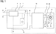
- FIG. 1 shows in the form of a schematic block diagram, an arrangement of components of a hybrid powertrain in a part of the electrical system 1 of a motor vehicle, in particular a commercial vehicle.
- the sub-board network 1 is connected in a conventional manner via a DC / DC converter 4 with a conventional electrical system 2, in which there are various consumers and a conventional battery.
- the sub-board network 1 can be operated, for example, with an increased low-voltage voltage in comparison to the main on-board network 2.
- an electrical energy store 5 in the form of an ultracap memory and an inverter (inverter) 10 and a switched reluctance machine 20 are arranged.
- the box marked with the reference numeral 3 is intended to denote no further component, but only the overall arrangement of DC-DC converter 4 and energy storage device 5.
- the reluctance machine 20 serves as a starter generator and can be operated both by motor and generator. During engine operation, the reluctance machine is supplied with energy from the energy store 5 via the inverter 10. In generator operation, the electrical energy generated by the reluctance machine can be stored by the energy store 5.
- the reluctance machine 20 is embodied in the exemplary embodiment as a three-phase reluctance motor 21. Each phase winding U, V, W of the reluctance motor 21 is guided with its positive and negative terminal 24 to the outside and connected to the inverter 10.
- the reluctance machine 20 further includes a rotor position sensor 22 and a temperature sensor 24. The measured values of the rotor position sensor 22 and the temperature sensor 24 are transmitted to the inverter 10 via signal lines 23.
- U H and U L denote the two potentials of the applied DC voltage.
- the supercap-memory 5 comprises, in a manner known per se, a control unit 5c with power electronics, which regulates the energy flows into and out of the supercap-memory cell module 5a.
- the supercap memory cell module can be disconnected from the onboard power supply 1 via an optional switch 5b.
- the inverter 10 determines the power and mode of operation of the reluctance machine 20, and is driven by a vehicle controller 6 in accordance with the power demand to the reluctance machine 20.
- the vehicle controller 6 is connected via a control line 7 to a microcontroller 11 of the inverter and also via further control lines 7 with the DC-DC converter 4 and the control unit 5c of the energy store. 5
- the microcontroller 11 of the inverter drives the three phase windings U, V, and W of the reluctance machine by means of controllable semiconductor switches S in the form of circuit breakers.
- controllable semiconductor switches S in the form of circuit breakers.
- the in FIG. 2 illustrated embodiment of the inverter 10 twelve switches S (S1 to S12) on.
- An intermediate circuit capacitor 13 serves as a suppression capacity and is connected to the operating voltage between U H and U L.
- the DC link capacitor 13 can of course also be arranged outside of the inverter 10.
- Each of the parallel three phase branches of the inverter 10 for driving a respective phase winding U, V, or W comprises two high-side switches S1 and S3 or S5 and S7 or S9 and S11 and two low-side switches S2 and S4 or S6 and S8 or S10 and S12.
- an uncontrollable semiconductor switching element in the form of a freewheeling diode 14 is connected in anti-parallel.
- the switches S1 to S12 are designed as power MOSFETs and are controlled by the microcontroller 11 in each case via the control lines 12 at its gate, which represents the control input.
- the microcontroller 11 switches the semiconductor switches S1 and S4 to passage, so that a current flows through the phase winding U. If the semiconductor switches S1 and S4 are then switched off again by the microcontroller 11, a discharge current of the phase winding (not that of the energy store) flows through the freewheeling diodes 14 of the switches S2 and S3. An energization of the phase winding U in the reverse direction is also possible. For this purpose, the semiconductor switches S3 and S2 are switched to passage. The discharge current of the phase winding (not that of the energy store) then flows through the freewheeling diodes 14 of the switches S1 and S4.
- the energization of the phase windings V and W takes place analogously via the respective switches of the associated phase branches.
- the electric machine 20 is designed in the illustrated embodiment, three-phase, but may also have more than three phases, wherein for each phase in each case the phase strands, as described above, are provided in the inverter 10.
- phase branches of the inverter 10 of the type described above is known per se.
- FIG. 3 a flowchart of a method for discharging the energy storage to a stop state according to an embodiment of the invention described.
- step S1 the predetermined activation conditions for a discharge operation of the ultracap memory 5 are continuously monitored and their fulfillment is checked (step S2).
- two different activation conditions for activating the discharge process are predetermined, so that in two independent cases, a discharge process can be triggered.
- a first activation condition ensures that the Ultracap memory 5 is automatically discharged to a predetermined Abstelldepth if the vehicle is turned off and then if an actual charging voltage of the energy storage is greater than the predetermined target Abstellschreib.
- the vehicle controller 6 thus checks whether the vehicle has been turned off, ie, by evaluating suitable parameters, it is checked whether the driver has parked the vehicle and probably a renewed driving operation is not imminent. This can be z. B. can be detected by means of a lock of the vehicle. If a shutdown has been detected, the vehicle controller 6 further checks whether the actual charging voltage of the ultracap memory 5 is greater than the desired Abstellschreib.
- the ultra-cap memory 5 may have a memory module of 20 cells each with 2.7 V of maximum charging voltage. When parked, however, the cells should be charged with a maximum of 2 V in order to improve the service life.
- the current charging voltage of the ultracap memory 5 is continuously transmitted from the control unit 5c to the vehicle controller 6 and can then be compared with the target Abstellschreib.
- the first activation condition is met when the actual charging voltage of the parked vehicle is above the target Abstellbrief, so that in this case in step S3, one of the phase windings U, V or W is selected, which is energized for the discharge process.
- phase winding is determined in which the rotor is in a position with the smallest or minimum magnetic reluctance or maximum or maximum inductance.
- This phase winding generates when energized with the discharge current, the lowest effective torque, so that movement of the rotor is energized when energized the phase winding is avoided and this phase winding or inductance can be used as a discharge resistor without the reluctance machine generates an effective torque.
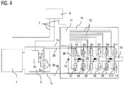
- step S4 the determined phase winding is used as a discharge resistor for the discharge current. If, for example, the phase U has been determined in step S3, the microcontroller 11 switches the semiconductor switches S1 and S4 to passage so that a discharge current flows through the phase winding U, which in FIG. 4 through line 30, which shows the discharge current. A discharge current could also flow in the opposite direction through the phase winding U. For this purpose, then the semiconductor switches S3 and S2 must be switched to passage. In contrast to the normal operation of the reluctance machine, the current supply generates no torque and no movement of the machine.
- the discharging process is terminated when the actual charging voltage has dropped to the desired Abstellbrief.
- the unloading process can also be started when a second activation condition is met.
- This second activation conditions initiates a complete discharge of the energy storage, if an error occurs in the energy storage, eg. As a failure of a cell of the energy storage, is diagnosed or performing service or maintenance is displayed, as already described above.
- the discharge process is again analogous to the steps S3 and S4.
Landscapes
- Engineering & Computer Science (AREA)
- Life Sciences & Earth Sciences (AREA)
- Sustainable Development (AREA)
- Sustainable Energy (AREA)
- Power Engineering (AREA)
- Transportation (AREA)
- Mechanical Engineering (AREA)
- Electric Propulsion And Braking For Vehicles (AREA)
- Control Of Electric Motors In General (AREA)
Abstract
Die Erfindung betrifft ein Verfahren zum Entladen eines Energiespeichers für elektrische Energie, der zur Versorgung einer elektrischen Maschine eines Kraftfahrzeugs vorgesehen ist. Die Erfindung betrifft insbesondere ein derartiges Verfahren, um den elektrischen Energiespeicher auf eine vorgegebene Abstellspannung zu entladen. Gemäß allgemeinen Gesichtspunkten der Erfindung ist die elektrische Maschine eine geschaltete Reluktanzmaschine, deren Phasenwicklungen (U, V, W) von einem Wechselrichter mit Hilfe von Schaltern angesteuert wird. Das Verfahren sieht vor, dass nach Erfüllung wenigstens einer Aktivierungsbedingung (S2) zur Aktivierung eines Entladevorgangs des Energiespeichers der Entladevorgang aktiviert wird, bei dem der Energiespeicher über die Reluktanzmaschine auf einen vorbestimmten Abstellzustand entladen wird, wobei mittels des Wechselrichters wenigstens eine Phasenwicklung als Entladewiderstand bestromt wird, bei der ein von einem Entladestrom erzeugtes Magnetfeld keine Kraft entwickelt, die groß genug ist, den Antriebstrang oder das Kraftfahrzeug zu bewegen (S3, S4).The invention relates to a method for discharging an energy store for electrical energy, which is provided for supplying an electrical machine of a motor vehicle. In particular, the invention relates to such a method for discharging the electrical energy store to a predetermined turn-off voltage. According to general aspects of the invention, the electric machine is a switched reluctance machine whose phase windings (U, V, W) are driven by an inverter by means of switches. The method provides that after fulfillment of at least one activation condition (S2) for activating a discharging process of the energy storage, the discharge process is activated, in which the energy storage is discharged via the reluctance machine to a predetermined Abstellzustand, wherein by means of the inverter at least one phase winding is energized as a discharge resistor in which a magnetic field generated by a discharge current does not develop a force large enough to move the drive train or the motor vehicle (S3, S4).
Description
Die Erfindung betrifft ein Verfahren zum Entladen eines Energiespeichers für elektrische Energie, der zur Versorgung einer elektrischen Maschine eines Kraftfahrzeugs vorgesehen ist. Die Erfindung betrifft insbesondere ein derartiges Verfahren, um den elektrischen Energiespeicher auf eine vorgegebene Abstellspannung zu entladen.The invention relates to a method for discharging an energy store for electrical energy, which is provided for supplying an electrical machine of a motor vehicle. In particular, the invention relates to such a method for discharging the electrical energy store to a predetermined turn-off voltage.
In Mildhybrid-, Hybrid- und Elektrofahrzeugen kommen häufig neben einer konventionellen 12 V- oder 24 V-Bleisäurebatterie zusätzliche elektrische Traktionsenergiespeicher zum Einsatz, die zur Versorgung einer elektrischen Maschine im Antriebsstrang vorgesehen sind. Ein derartiger zusätzlicher Energiespeicher ist häufig als Lithium-Ionen-Akkumulator oder als Ultrakondensatorspeicher (kurz auch als Ultracap bezeichnet) ausgeführt. Aufgrund von Versuchsdaten und wissenschaftlichen Untersuchungen ist bekannt, dass beim Einsatz von derartigen Ultrakondensatorspeichern ein Lagern des Energiespeichers mit hohen Ladespannungen, insbesondere im vollständig aufgeladenen Zustand, schädlich für die Lebensdauerhaltbarkeit des Energiespeichers ist.In mild hybrid, hybrid and electric vehicles, in addition to a conventional 12 V or 24 V lead-acid battery, additional electric traction energy storage devices are used, which are provided for supplying an electric machine in the drive train. Such an additional energy storage device is often designed as a lithium-ion battery or as an ultra-capacitor storage (also referred to as ultracap for short). On the basis of experimental data and scientific investigations, it is known that storage of the energy store with high charging voltages, in particular when fully charged, is detrimental to the service life of the energy store when such ultra-capacitor stores are used.
Demzufolge stellt sich das Problem, wie ein derartiger zusätzlicher Energiespeicher beim Abstellen eines Fahrzeugs und wenn der Ladezustand des Energiespeicher einen für die Lebensdauer optimalen Soll-Abstellschwellenwert überschreitet, geeignet entladen werden kann, um den Ladezustand des Energiespeichers auf eine vorgegebene Abstellspannung abzusenken.Consequently, the problem arises, such as such an additional energy storage when parking a vehicle and when the state of charge of the energy storage exceeds a lifetime optimal Soll-Abstellschwellenwert can be discharged properly to lower the state of charge of the energy storage to a predetermined Abstellspannung.
Aus der Praxis ist bekannt, einen zusätzlichen Entladewiderstand vorzusehen, der durch einen Schalter aktiviert wird. Nachteilig hieran ist, dass dies zusätzliche Bauteile erfordert und folglich einen erhöhten Bauraumbedarf und Kosten verursacht, sowie zum Auftreten zusätzlicher Fehlermodi und einer geringeren Verfügbarkeit führen kann.From practice it is known to provide an additional discharge resistor, which is activated by a switch. The disadvantage of this is that this requires additional components and consequently causes increased space requirements and costs, and can lead to the occurrence of additional failure modes and a lower availability.
Eine alternative Möglichkeit wäre die Verwendung ggf. vorhandener Symmetriewiderstände- bzw. -schaltungen, die ausgelegt sind, Unterschiede zwischen den einzelnen Zellen des Energiespeichers langsam auszugleichen. Die übliche thermische Dimensionierung und Leistungsdimensionierung dieser Schaltungen sind jedoch nicht für das Entladen des gesamten Energiespeichers innerhalb eines zweckmäßigen Zeitfensters geeignet. Hierfür müssten diese Schaltungsteile entsprechend erweitert werden, was wiederum Kostensteigerungen nach sich ziehen würde.An alternative possibility would be the use of possibly existing Symmetriewiderstände- or circuits, which are designed to compensate for differences between the individual cells of the energy storage slowly. The usual thermal dimensioning and power dimensioning of these circuits, however, are not suitable for discharging the entire energy store within a convenient time window. For this, these circuit parts would have to be expanded accordingly, which in turn would entail cost increases.
Derartige zusätzliche Energiespeicher sind ferner oftmals in einem Teilbordnetz (Inselnetz) mit erhöhter Nennspannung angeordnet, das über einen Gleichspannungswandler (DC/DC-Wandler) mit dem konventionellen Bordnetz gekoppelt ist. Eine weitere Möglichkeit, den zusätzlichen Energiespeicher zu entladen, wäre daher, eine Teilenergie des zusätzlichen Energiespeichers beim Abstellen vom Inselnetz über den Gleichspannungswandler (DC/DC-Wandler) ins konventionelle Bordnetz zu transferieren. Aus der Praxis ist jedoch bekannt, dass die konventionelle 12 V- oder 24 V-Batterie in Mildhybrid-, Hybrid- und Elektrofahrzeugen ebenfalls in der Regel einen hohen Ladezustand aufweist, so dass diese die abzugebende Energie des zusätzlichen Energiespeichers beim Abstellen des Fahrzeugs dann nicht aufnehmen kann, so dass dieser Ansatz keine zuverlässige Entladung ermöglicht. Diese Möglichkeit des Entladens scheidet ferner dann aus, wenn keine energetische Brücke zwischen dem Teilbordnetz und dem konventionellen Bordnetz vorgesehen ist.Such additional energy storage are also often arranged in a sub-board network (island grid) with increased nominal voltage, which is coupled via a DC-DC converter (DC / DC converter) to the conventional electrical system. Another way to discharge the additional energy storage, would therefore be to transfer a partial energy of the additional energy storage when switching off the island grid on the DC-DC converter (DC / DC converter) in the conventional electrical system. From practice, however, it is known that the conventional 12 V or 24 V battery in Mildhybrid-, hybrid and electric vehicles also usually has a high state of charge, so that they are not the energy of the additional energy storage when parking the vehicle so that this approach does not allow reliable discharge. This possibility of discharging is also eliminated if no energy bridge between the sub-board network and the conventional electrical system is provided.
Es ist somit eine Aufgabe der Erfindung, ein verbessertes Verfahren zum Entladen eines Energiespeichers für elektrische Energie, der zur Versorgung einer elektrischen Maschine eines Kraftfahrzeugs vorgesehen ist, bereitzustellen, mit dem Nachteile bekannter Ansätze vermieden werden können. Die Aufgabe der Erfindung ist es insbesondere, ein derartiges Verfahren bereitzustellen, mit dem eine kostengünstige Möglichkeit geschaffen wird, um den elektrischen Energiespeicher sicher auf einen vorgegebenen Abstellzustand zu entladen.It is therefore an object of the invention to provide an improved method for discharging an energy store for electrical energy, which is provided for supplying an electrical machine of a motor vehicle, can be avoided with the disadvantages of known approaches. The object of the invention is in particular to provide such a method, with which a cost-effective way is provided to safely discharge the electrical energy storage to a predetermined Abstellzustand.
Diese Aufgaben werden durch ein Verfahren mit den Merkmalen des Hauptanspruchs gelöst. Vorteilhafte Ausführungsformen und Anwendungen der Erfindung ergeben sich aus den abhängigen Ansprüchen und werden in der folgenden Beschreibung unter teilweiser Bezugnahme auf die Figuren näher erläutert.These objects are achieved by a method having the features of the main claim. Advantageous embodiments and applications of the invention will become apparent from the dependent claims and are explained in more detail in the following description with partial reference to the figures.
Die Erfindung beruht auf der technischen Erkenntnis, dass eine kostengünstige und variable Möglichkeit zum Entladen eines elektrischen Energiespeichers auf einen vorbestimmten Abstellzustand mittels einer Reluktanzmaschine, insbesondere einer geschalteten Reluktanzmaschine, bereitgestellt werden kann.The invention is based on the technical knowledge that a cost-effective and variable possibility for discharging an electrical energy store to a predetermined parking state by means of a reluctance machine, in particular a switched reluctance machine can be provided.
Geschaltete Reluktanzmaschinen werden auch mit der Abkürzung SRM bezeichnet, die von der englischen Bezeichnung "switched reluctance motor" abgeleitet ist. Die Reluktanzmaschinen können beispielsweise eine unterschiedliche Anzahl von Zähnen an Rotor und Stator besitzen, wobei Statorzähne mit Magnetspulen umwickelt sind. Im Betrieb der Reluktanzmaschine werden die Magnetspulen abwechselnd so ein- und ausgeschaltet, dass die Zähne am Rotor in Richtung der bestromten Magnetspulen bzw. der Statorzähne bewegt werden. Daraufhin wird in der nächsten Schaltphase dann auf Magnetspulen anderer Statorzähne umgeschaltet, so dass diese den Rotor zur Weiterdrehung veranlassen. Die aufeinanderfolgenden Schaltphasen der verwendeten Magnetspulen sorgen somit insgesamt dafür, dass der Rotor in Rotation versetzt wird.Switched reluctance machines are also referred to by the abbreviation SRM, which is derived from the English term "switched reluctance motor". The reluctance machines may, for example, have a different number of teeth on the rotor and the stator, with stator teeth being wound with magnetic coils. During operation of the reluctance machine, the magnetic coils are alternately switched on and off so that the teeth on the rotor move in the direction of the energized magnetic coils or the stator teeth become. Then, in the next switching phase then switched to magnetic coils of other stator teeth, so that they cause the rotor to continue rotation. The successive switching phases of the magnetic coils used thus ensure overall that the rotor is set in rotation.
Im Gegensatz zu Wechselstrommaschinen wird eine geschaltete Reluktanz (SR)-Maschine gewickelt, indem konzentrierte Wicklungen benutzt werden, d. h. Wicklungen, die auf vorstehenden Motorpolen konzentriert sind. Infolgedessen sind die Phasenwicklungen einer SR-Maschine im Wesentlichen frei von jeder magnetischen Kopplung, so dass hohe Ströme in einer Wicklung keine hohen Ströme in benachbarten Phasenwicklungen magnetisch induzieren. Die Erfindung nutzt diese charakteristische magnetische Unabhängigkeit der Phasen von geschalteten Reluktanzmaschinen als Basis für das erfindungsgemäße Entladen des Energiespeichers aus.Unlike AC machines, a switched reluctance (SR) machine is wound using concentrated windings, i. H. Windings concentrated on protruding motor poles. As a result, the phase windings of an SR machine are substantially free of any magnetic coupling, so that high currents in one winding do not magnetically induce high currents in adjacent phase windings. The invention exploits this characteristic magnetic independence of the phases of switched reluctance machines as the basis for discharging the energy store according to the invention.
Der erfindungsgemäße Ansatz beruht darauf, eine vorhandene Phaseninduktivität, vorzugsweise beim Stillstand der Reluktanzmaschine, als Entladewiderstand zu verwenden, wobei hierzu diejenige(n) Phaseninduktivität(en) ausgewählt wird bzw. werden, deren Rotorposition so ist, dass das resultierende Magnetfeld bei einer Bestromung der Phaseninduktivität keine Kraft entwickelt, die groß genug ist, den Motor, den Triebstrang oder das gesamte Fahrzeug zu bewegen. Somit kann ein Risiko einer ungewollten Beschleunigung vermieden werden.The approach according to the invention is based on using an existing phase inductance, preferably when the reluctance machine is at a standstill, as a discharge resistor, for which purpose the phase inductance (s) is / are selected whose rotor position is such that the resulting magnetic field is energized when the reluctance current is applied Phase inductance develops no force large enough to move the engine, the drivetrain or the entire vehicle. Thus, a risk of unwanted acceleration can be avoided.
Gemäß allgemeinen Gesichtspunkten der Erfindung wird somit ein Verfahren zum Entladen eines Energiespeichers für elektrische Energie, der zur Versorgung einer elektrischen Maschine eines Kraftfahrzeugs vorgesehen ist, bereitgestellt, wobei die elektrische Maschine eine geschaltete Reluktanzmaschine ist, deren Phasenwicklungen von einem Wechselrichter, auch als Inverter bezeichnet, mit Hilfe von Schaltern, insbesondere Leistungsschaltern, angesteuert wird. Die Reluktanzmaschine ist vorzugsweise dreiphasig ausgeführt, kann aber auch mehr Phasen haben. Erfindungsgemäß wird nach Erfüllung wenigstens einer Aktivierungsbedingung zur Aktivierung eines Entladevorgangs des Energiespeichers der Entladevorgang aktiviert, bei dem der Energiespeicher über die Reluktanzmaschine auf einen vorbestimmten Abstellzustand entladen wird. Hierbei wird mittels des Wechselrichters wenigstens eine Phasenwicklung als Entladewiderstand bestromt, bei der ein von einem Entladestrom erzeugtes Magnetfeld keine Kraft oder kein Drehmoment entwickelt, die oder das groß genug ist, den Antriebsstrang oder das Kraftfahrzeug zu bewegen.According to general aspects of the invention, there is thus provided a method for discharging an energy store for electrical energy intended to supply an electric machine of a motor vehicle, the electric machine being a switched reluctance machine whose phase windings are designated by an inverter, also referred to as an inverter. is controlled by means of switches, in particular circuit breakers. The reluctance machine is preferably designed in three phases, but may also have more phases. According to the invention, after the fulfillment of at least one activation condition for activating a discharging process of the energy store, the discharging process is activated, in which the energy store is discharged to a predetermined stop state via the reluctance machine. Here, by means of the inverter, at least one phase winding is energized as a discharge resistor, in which a magnetic field generated by a discharge current develops no force or torque that is large enough to move the drive train or the motor vehicle.
Das erfindungsgemäße Verfahren ist besonders vorteilhaft, bei Fahrzeugen oder Antriebsstrangkonzepten, bei denen ggf. aus anderen Erwägungen eine Reluktanzmaschine zum Einsatz kommt oder kommen soll. In diesem Fall können eine bereits vorhandene Komponente in Form der Reluktanzmaschine und deren vorhandene Funktionalitäten genutzt werden, um eine Entladefunktionalität kostengünstig bereitzustellen. Der Stromfluss für den Entladevorgang kann durch entsprechende Ansteuerung der (Leistungs-)Schalter des Wechselrichters gesteuert werden.The method according to the invention is particularly advantageous in vehicles or powertrain concepts in which a reluctance machine is or is intended to be used for other considerations. In this case, an already existing component in the form of the reluctance machine and its existing functionalities can be used to inexpensively provide a discharge functionality. The current flow for the discharge process can be controlled by appropriate control of the (power) switch of the inverter.
Ein Energiespeicher für elektrische Energie wird nachfolgend auch als elektrischer Energiespeicher oder kurz Energiespeicher bezeichnet.An energy store for electrical energy is also referred to below as an electrical energy store or short energy store.
Gemäß einer bevorzugten Ausführungsform kann diejenige Phasenwicklung zur Bestromung mit dem Entladestrom ausgewählt werden, bei der der Entladestrom das geringste wirksame Drehmoment erzeugt, so dass eine Bewegung des Rotors bei Bestromung der Phasenwicklung vermieden wird. Das geringste wirksame Drehmoment erzeugt bekanntermaßen diejenige Phasenwicklung der Reluktanzmaschine, bei der sich der Rotor in einer Position mit der kleinsten oder minimalen magnetischen Reluktanz bzw. größten oder maximalen Induktanz befindet. Ist beispielsweise ein Rotorpol exakt mit einem Statorpol ausgerichtet, dann ist die Maschine in der ausgerichteten Position. Wenn Strom in der entsprechenden Statorpolwindung fließt, wird kein Drehmoment erzeugt, weil sich der Rotor in einer Position von maximaler Induktanz und folglich minimaler magnetischer Reluktanz befindet. Diese Phasenwicklung kann aus den verschiedenen Phasenwicklungen mittels eines Motorlagegebers, z. B. eines Rotorlagegebers bestimmt werden. Alternativ kann aber auch eine geberlose Auswahl der Phasenwicklung erfolgen, analog zu an sich bekannten geberlosen Steuerverfahren anhand des Statorstroms oder des Drehmomentes.According to a preferred embodiment, that phase winding can be selected for energization with the discharge current at which the discharge current generates the lowest effective torque, so that movement of the rotor is avoided when the phase winding is energized. The lowest effective torque is known to produce that phase winding of the reluctance machine where the rotor is in a position of least or minimum magnetic reluctance, or maximum or maximum inductance. For example, if a rotor pole is exactly aligned with a stator pole, then the machine is in the aligned position. When current flows in the corresponding stator pole winding, no torque is generated because the rotor is in a position of maximum inductance and, hence, minimal magnetic reluctance. This phase winding can from the various phase windings by means of a motor position sensor, z. B. a rotor position sensor can be determined. Alternatively, however, a sensorless selection of the phase winding can also take place, analogously to known sensorless control methods based on the stator current or the torque.
Gemäß einer weiteren bevorzugten Ausführungsform können während des Entladens bzw. zum Entladen des Energiespeichers mindestens zwei Phasenwicklungen der Reluktanzmaschine als Entladewiderstände gleichzeitig oder nacheinander bestromt werden. Da der Verlauf der Kraft, die von dem durch eine bestromte Phasenwicklung erzeugten Magnetfeld erzeugt wird, exponentiell in Abhängigkeit von der Drehposition ist, gibt es z. B. bei einer zumindest dreiphasigen Reluktanzmaschine neben der Phasenwicklung mit minimaler magnetischer Reluktanz immer noch mindestens eine weitere Phasenwicklung, die bestromt werden kann, ohne dass ein Drehmoment erzeugt wird, das den Motor oder das Fahrzeug bewegen kann.According to a further preferred embodiment, at least two phase windings of the reluctance machine can be energized as discharge resistors simultaneously or successively during the discharging or for discharging the energy store. Since the course of the force generated by the magnetic field generated by a current-energized phase winding is exponential depending on the rotational position, there are, for. For example, in an at least three-phase reluctance machine in addition to the phase winding with minimal magnetic reluctance still at least one other phase winding, which can be energized without a torque is generated, which can move the engine or the vehicle.
Eine Bestromung von zwei Phaseninduktivitäten zum Entladen des Energiespeichers bietet den Vorteil, dass die beim Entladevorgang entstehende Verlustwärme in den Phaseninduktivitäten, die als Entladewiderstände dienen, auf zwei Phasenstränge verteilt werden kann, so dass eine zu starke Erwärmung der Schalter des Phasenstrangs besser vermieden werden kann.An energization of two Phaseninduktivitäten for discharging the energy storage has the advantage that the heat loss during the discharge process in the Phaseninduktivitäten that serve as discharge, can be distributed over two phase strands, so that excessive heating of the switch of the phase strand can be better avoided.
Gemäß einer weiteren Ausführungsform der Erfindung wird während des Entladens des Energiespeichers die Richtung des Entladestroms durch eine Phasenwicklung umgekehrt. Diese Variante setzt voraus, dass jeder der parallelen Phasenzweige des Wechselrichters zur Ansteuerung jeweils einer Phasenwicklung eine Vollbrückenschaltung aus zwei High-Side-Schaltern und zwei Low-Side-Schaltern umfasst, wobei zu jedem High-Side- und Low-Side-Schalter ein nicht steuerbares Halbleiterschaltelement in Form einer Freilaufdiode antiparallel geschaltet ist. Die Umkehrung der Richtung des Entladestroms durch eine Phasenwicklung während des Entladevorgangs bietet wiederum den Vorteil, dass beim Entladevorgang entstehende Verlustwärme besser in der Elektronik verteilt werden kann, und zwar gemäß dieser Variante auf die einzelnen Schalter des Phasenstrangs.According to a further embodiment of the invention, the direction of the discharge current is reversed by a phase winding during the discharge of the energy store. This variant assumes that each of the parallel phase branches of the inverter for driving one phase winding each comprises a full-bridge circuit comprising two high-side switches and two low-side switches, with one not for each high-side and low-side switch controllable semiconductor switching element in the form of a freewheeling diode is connected in anti-parallel. The reversal of the direction of the discharge current through a phase winding during the discharge process again offers the advantage that heat loss arising during the discharge process can be better distributed in the electronics, specifically according to this variant to the individual switches of the phase strand.
Falls beispielsweise der gesamte Entladevorgang über nur eine Phasenwicklung in einer Stromrichtung erfolgt, werden nur zwei Bauteile, je nach Stromrichtung der rechte High-Side-Schalter und der linke Low-Side-Schalter oder der linke High-Side-Schalter und der rechte Low-Side-Schalter, thermisch belastet. Wird die Stromrichtung jedoch ein oder mehrmals während des Entladens umgekehrt, kann die thermische Belastung auf alle Schalter des Phasenstrangs verteilt werden. Eine Umkehr der Stromrichtung hat bei der Reluktanzmaschine bekanntermaßen keine Auswirkung auf die Richtung des erzeugten Drehmoments.If, for example, the entire discharge process takes place over only one phase winding in one current direction, only two components, depending on the current direction, the right high-side switch and the left low-side switch or the left high-side switch and the right low Side switch, thermally loaded. However, if the current direction is reversed one or more times during discharge, the thermal load can be distributed to all switches of the phase strand. A reversal of the current direction is known to have no effect on the direction of the torque generated in the reluctance machine.
Das Umschalten der Stromrichtung innerhalb einer Phasenwicklung und/oder das Wechseln auf eine zweite Phaseninduktivität, wie vorstehend beschrieben, kann vorzugsweise in Abhängigkeit von einer Steuergröße erfolgen, die ein Maß für die durch den Entladestrom entstehende Verlustwärme ist. Beispiele für die Steuergröße könnten die Temperatur der Schalter des Wechselrichters oder eine Dauer und Stärke des Entladestroms sein. Wenn die Steuergröße einen vorbestimmten Schwellenwert überschreitet, kann dann die Stromrichtung und/oder die bestromte Phasenwicklung gewechselt werden.The switching of the current direction within a phase winding and / or the switching to a second phase inductance, as described above, can preferably take place as a function of a control variable which is a measure of the heat loss resulting from the discharge current. Examples of the control variable could be the temperature of the switches of the inverter or a duration and magnitude of the discharge current. If the control variable exceeds a predetermined threshold, then the current direction and / or the energized phase winding can be changed.
Selbstverständlich können die parallelen Phasenzweige des Wechselrichters zur Ansteuerung jeweils einer Phasenwicklung auch durch eine erste Reihenschaltung eines High-Side-Schalters mit einer Freilaufdiode und eine zweite Reihenschaltung einer Freilaufdiode mit einem Low-Side-Schalter gebildet sein, d.h. durch zwei asymmetrische Halbbrücken pro Strang gebildet sein. Gemäß dieser Variante ist der Schalttransistor der ersten Reihenschaltung mit dem positiven Pol und der Schalttransistor der zweiten Reihenschaltung mit dem negativen Pol einer Gleichspannungsquelle verbunden. Die Freilaufdioden sind in Bezug auf die Polarität der Gleichspannungsquelle in Sperrrichtung gepolt. Gemäß dieser Variante ist dann eine Umkehr der Stromrichtung beim Entladevorgang nicht möglich.Of course, the parallel phase branches of the inverter for driving a respective phase winding by a first series connection of a high-side switch with a freewheeling diode and a second series connection of a freewheeling diode with be formed a low-side switch, ie be formed by two asymmetric half-bridges per strand. According to this variant, the switching transistor of the first series circuit is connected to the positive pole and the switching transistor of the second series circuit is connected to the negative pole of a DC voltage source. The freewheeling diodes are poled in reverse direction with respect to the polarity of the DC voltage source. According to this variant, a reversal of the current direction during the discharge process is not possible.
Ein weiterer Aspekt der Erfindung sieht vor, dass eine erste Aktivierungsbedingung zur Aktivierung eines Entladevorgangs erfüllt ist, wenn eine Ist-Ladespannung des Energiespeichers größer ist als ein vorbestimmter Schwellenwert, der als Soll-Abstellspannung vorgegeben wird, und das Kraftfahrzeug abgestellt wurde. Die Überwachung der Ist-Ladespannung ist üblicherweise eine vorhandene Funktionalität bei Fahrzeugen mit hybridisiertem Antriebsstrang, so dass keine zusätzliche Sensorik benötigt wird. Das Abstellen des Fahrzeugs kann beispielsweise durch das Verriegeln des Fahrzeugs, das Ausschalten der Zündung und/oder durch andere geeignete Parameter erkannt werden, aus denen abgeleitet werden kann, dass der Fahrer das Fahrzeug abgestellt hat und wahrscheinlich ein erneuter Fahrbetrieb nicht unmittelbar bevorsteht. Gemäß dieser Variante wird der vorbestimmte Abstellzustand erreicht, wenn die Ladespannung des Energiespeichers auf den vorbestimmten Schwellenwert (Soll-Abstellspannung) abgesunken ist. Lediglich beispielhaft kann bei einer Zelle eines Ultracaps, die eine maximale Ladespannung von 2,7 V aufweist, eine Soll-Abstellspannung pro Zelle von 2 V vorgeben werden. Bei diesem Aspekt der Erfindung wird somit beim Abstellen des Fahrzeugs geprüft, ob der Energiespeicher entladen werden muss, und dadurch vermieden, dass der Energiespeicher ungenutzt in einem Zustand zu hoher Ladespannung lagert und die Lebensdauerhaltbarkeit dadurch beeinträchtigt wird.A further aspect of the invention provides that a first activation condition for activating a discharging process is fulfilled when an actual charging voltage of the energy accumulator is greater than a predetermined threshold value, which is specified as a target Abstellspannung, and the motor vehicle has been turned off. The monitoring of the actual charging voltage is usually an existing functionality in vehicles with hybridized powertrain, so that no additional sensors are needed. The parking of the vehicle can be detected, for example, by the locking of the vehicle, the switching off of the ignition and / or by other suitable parameters, from which it can be deduced that the driver has parked the vehicle and probably a re-driving operation is not imminent. According to this variant, the predetermined Abstellzustand is reached when the charging voltage of the energy storage has dropped to the predetermined threshold (target Abstellspannung). For example only, for a cell of an ultracaps having a maximum charge voltage of 2.7V, a target cutoff voltage per cell of 2V may be specified. In this aspect of the invention is thus checked when parking the vehicle, if the energy storage must be discharged, and thereby prevents the energy storage unused stored in a state of high charging voltage and the service life is impaired.
Gemäß einer weiteren Ausführungsvariante kann eine zweite Aktivierungsbedingung zur Aktivierung eines Entladevorgangs vorgegeben werden, die dann erfüllt ist, wenn ein Fehlerfall im Energiespeicher, z. B. ein Ausfall einer Zelle des Energiespeichers, diagnostiziert wird oder ein Durchführen von Service- oder Wartungsarbeiten angezeigt wird, wobei der vorbestimmte Abstellzustand erreicht ist, wenn der Energiespeicher vollständig entladen wurde. Gemäß dieser Variante kann aus Sicherheitsgründen ein Entladevorgang eingeleitet werden, um im Fehlerfall einen unsicheren Fahrbetrieb oder weitere Beschädigungen zu vermeiden oder um bei Service- oder Wartungsarbeiten den Service-Arbeiter keinem Risiko einer hohen Spannung auszusetzen. Ein Fehlerfall im Energiespeicher kann anhand der an sich bekannten Fehlerdiagnostikfunktionalität ermittelt werden, die üblicherweise bei herkömmlichen Traktionsenergiespeichern eingesetzt werden. Das Anzeigen von Service- oder Wartungsarbeiten kann beispielsweise durch Nutzung der On-Board-Diagnostik-Schnittstelle, durch Betätigung eines Entladeknopfs oder eine Entladeaufforderung des Energiespeichers angezeigt werden.According to a further embodiment, a second activation condition for activating a discharge process can be specified, which is then fulfilled when an error occurs in the energy storage, for. As a failure of a cell of the energy storage device, is diagnosed or a performing service or maintenance is displayed, the predetermined Abstellzustand is reached when the energy storage has been completely discharged. According to this variant, a discharge process can be initiated for safety reasons to avoid in the event of an error unsafe driving or further damage or to suspend the service worker during service or maintenance work no risk of high voltage. An error in the energy storage can be determined by the known per se diagnostic diagnostic functionality, which is usually in conventional Traction energy storage can be used. The display of service or maintenance work can be displayed, for example, by using the on-board diagnostic interface, by pressing a discharge button or by unloading the energy storage device.
Bei einer vorteilhaften Variante der beiden vorgenannten Beispiele von Aktivierungsbedingungen wird der Entladestrom bei Erfüllung der ersten Aktivierungsbedingung mittels einer Steuereinheit des Wechselrichters auf eine erste Größe und bei Erfüllung der zweiten Aktivierungsbedingung auf eine zweite Größe eingestellt, wobei die erste Größe kleiner als die zweite Größe ist. Mit anderen Worten wird bei einem aus Sicherheitsgründen getriggerten Entladevorgang eine schnellere Entladung des Energiespeichers veranlasst.In an advantageous variant of the two aforementioned examples of activation conditions, the discharge current is set to a first variable when the first activation condition is satisfied by means of a control unit of the inverter and set to a second value when the second activation condition is satisfied, the first size being smaller than the second size. In other words, a discharging process triggered for safety reasons causes a faster discharge of the energy store.
Dies verdeutlicht einen weiteren Vorteil des erfindungsgemäßen Ansatzes. Mittels der Steuereinheit des Wechselrichters kann die Stromstärke des Stromflusses durch die Phasenwicklung durch entsprechende Ansteuerung der Halbleiterschalter der Phasenstränge des Wechselrichters gesteuert werden. Somit kann mit einer bestehenden Anordnung aus Wechselrichter und Reluktanzmaschine auch die Größe des Entladestroms für den Entladevorgang gesteuert und variiert werden, um je nach Aktivierungsbedingung oder Zweck des Entladevorgangs die Geschwindigkeit des Entladevorgangs anzupassen. Mit einem herkömmlichen passiven Entladewiderstand wäre dies nicht möglich.This illustrates a further advantage of the approach according to the invention. By means of the control unit of the inverter, the current intensity of the current flow through the phase winding can be controlled by appropriate control of the semiconductor switches of the phase phases of the inverter. Thus, with an existing arrangement of inverter and reluctance machine, the size of the discharging current for the discharging operation can be controlled and varied to adjust the speed of discharging depending on the activation condition or purpose of the discharging operation. With a conventional passive discharge resistor this would not be possible.
Vorzugsweise findet der Entladevorgang im Stillstand des Fahrzeugs und/oder bei abgestelltem Fahrzeug statt, d. h. bei einem Zustand, wo sich der Rotor der Reluktanzmaschine nicht dreht. Gemäß einer weiteren Ausführungsvariante des Verfahrens wird dies jedoch bei einem Fahrbetrieb des Fahrzeugs durchgeführt. Hierbei kann der Entladevorgang während des Betriebs der Reluktanzmaschine aktiviert werden, z. B. im Fall eines sicherheitskritischen Fehlerfalls. In diesem Fall ist die Steuereinheit des Wechselrichters gemäß dieser Variante eingerichtet, einen gepulsten Entladevorgang auszuführen, bei dem die Phasenwicklungen der Reluktanzmaschine nacheinander gepulst bestromt werden, wobei jeweils diejenige Phasenwicklung mit einem Entladestrom des Energiespeichers bestromt wird, die aktuell das kleinste Drehmoment erzeugt. Hierbei wird beispielsweise jeweils diejenige Phasenwicklung durch Kurzschließen des High-Side-Schalters und Low-Side-Schalters des zugeordneten Phasenzweigs bestromt, die im bestromten Zustand das kleinste Drehmoment erzeugt bzw. bei der sich der Rotor in einer Position mit minimaler magnetischer Reluktanz befindet.The unloading process preferably takes place when the vehicle is at a standstill and / or when the vehicle is parked, ie at a state where the rotor of the reluctance machine is not rotating. According to a further embodiment variant of the method, however, this is carried out during a driving operation of the vehicle. In this case, the discharge process can be activated during operation of the reluctance machine, z. B. in the case of a safety-critical error case. In this case, the control unit of the inverter according to this variant is adapted to perform a pulsed discharge, in which the phase windings of the reluctance machine are energized pulsed successively, wherein in each case that phase winding is energized with a discharge current of the energy storage, which currently generates the smallest torque. In this case, for example, each of the phase winding is energized by short-circuiting of the high-side switch and low-side switch of the associated phase branch, which generates the smallest torque in the energized state or in which the rotor is in a position with minimal magnetic reluctance.
Wahlweise ist es auch möglich, durch ein zeitgleiches geeignetes Bestromen aller Motorphasen ein Summendrehmoment von 0 zu erzeugen und den Energiespeicher zu entladen. Dies ist möglich, weil die einzelnen Phasen der Maschine nicht elektrisch oder magnetisch miteinander verbunden sind.Optionally, it is also possible to generate a total torque of 0 by a simultaneous suitable energizing of all motor phases and to discharge the energy store. This is possible because the individual phases of the machine are not electrically or magnetically interconnected.
Die Schalter des Wechselrichters sind vorzugsweise als Halbleiterschalter, weiter vorzugsweise als Leistungs-MOSFETS ausgebildet. Die Reluktanzmaschine kann als Startergenerator ausgeführt sein. Der Energiespeicher für elektrische Energie kann ein Lithium-Ionen-Speicher oder ein Kondensatorspeicher, insbesondere ein Ultra-Cap-Speicher, sein. Ferner kann das Kraftfahrzeug ein als Mildhybrid-, Hybrid- oder Elektrofahrzeug ausgeführtes Kraftfahrzeug, insbesondere ein derartiges Nutzfahrzeug sein.The switches of the inverter are preferably designed as semiconductor switches, more preferably as power MOSFETs. The reluctance machine can be designed as a starter generator. The energy store for electrical energy may be a lithium-ion storage or a capacitor storage, in particular an ultra-cap storage. Furthermore, the motor vehicle may be a motor vehicle designed as a mild hybrid, hybrid or electric vehicle, in particular such a commercial vehicle.
Die Erfindung betrifft ferner ein Kraftfahrzeug, insbesondere ein Nutzfahrzeug, mit einer Steuervorrichtung, insbesondere eine Steuereinheit für den Wechselrichter der Reluktanzmaschine, die eingerichtet ist, das erfindungsgemäße Verfahren auszuführen.The invention further relates to a motor vehicle, in particular a utility vehicle, with a control device, in particular a control unit for the inverter of the reluctance machine, which is configured to carry out the method according to the invention.
Die zuvor beschriebenen bevorzugten Ausführungsformen und Merkmale der Erfindung sind beliebig miteinander kombinierbar. Zur Vermeidung von Wiederholungen sollen ferner rein verfahrensgemäß offenbarte Merkmale auch als vorrichtungsgemäß offenbart gelten und beanspruchbar sein. Weitere Einzelheiten und Vorteile der Erfindung werden im Folgenden unter Bezug auf die beigefügten Zeichnungen beschrieben. Es zeigen:
Figur 1- ein schematisches Blockschaltbild eines Teilbordnetzes mit einem elektrischen Energiespeicher, einem Inverter und einer Reluktanzmaschine gemäß einer Ausführungsform der Erfindung;
Figur 2- ein schematisches Blockschaltbild des Teilbordnetzes und einen schematischen Aufbau des Wechselrichters gemäß einer Ausführungsform der Erfindung;
Figur 3- ein Ablaufdiagramm eines Verfahrens zum Entladen des Energiespeichers auf einen Abstellzustand gemäß einer Ausführungsform der Erfindung; und
Figur 4- einen Entladestrom anhand des Blockschaltbilds der
Figur 2
- FIG. 1
- a schematic block diagram of a sub-electrical system with an electrical energy storage, an inverter and a reluctance machine according to an embodiment of the invention;
- FIG. 2
- a schematic block diagram of the sub-electrical system and a schematic structure of the inverter according to an embodiment of the invention;
- FIG. 3
- a flowchart of a method for discharging the energy storage to a stop state according to an embodiment of the invention; and
- FIG. 4
- a discharge current based on the block diagram of
FIG. 2 ,
Gleiche oder äquivalente Komponenten sind in allen Figuren mit den gleichen Bezugszeichen bezeichnet.Identical or equivalent components are denoted by the same reference numerals in all figures.
Das Teilbordnetz 1 ist in an sich bekannter Weise über einen DC/DC-Wandler 4 mit einem konventionellen Bordnetz 2 verbunden, in dem sich verschiedene Verbraucher und eine konventionelle Batterie befinden. Das Teilbordnetz 1 kann beispielsweise mit einer erhöhten Niedervoltspannung im Vergleich zum Hauptbordnetz 2 betrieben werden. Im Teilbordnetz 1 sind ein elektrischer Energiespeicher 5 in Form eines Ultracap-Speichers sowie ein Wechselrichter (Inverter) 10 und eine geschaltete Reluktanzmaschine 20 angeordnet. Der mit dem Bezugszeichen 3 gekennzeichnete Kasten soll kein weiteres Bauteil, sondern lediglich die Gesamtanordnung aus Gleichspannungswandler 4 und Energiespeicher 5 kennzeichnen.The
Die Reluktanzmaschine 20 dient als Startergenerator und kann sowohl motorisch als auch generatorisch betrieben werden. Im motorischen Betrieb wird die Reluktanzmaschine über den Wechselrichter 10 mit Energie vom Energiespeicher 5 versorgt. Im generatorischen Betrieb kann die von der Reluktanzmaschine erzeugte elektrische Energie vom Energiespeicher 5 gespeichert werden. Die Reluktanzmaschine 20 ist im Ausführungsbeispiel als dreiphasiger Reluktanzmotor 21 ausgeführt. Jede Phasenwicklung U, V, W des Reluktanzmotors 21 ist mit ihrem positiven und negativen Anschluss 24 nach außen geführt und an den Inverter 10 angeschlossen. Die Reluktanzmaschine 20 umfasst ferner einen Rotorlagegeber 22 und einen Temperatursensor 24. Die Messwerte des Rotorlagegebers 22 und des Temperatursensors 24 werden über Signalleitungen 23 an den Wechselrichter 10 übertragen. UH und UL bezeichnen die beiden Potentiale der anliegenden Gleichspannung.The
In
Der Wechselrichter 10 bestimmt Leistung und Betriebsart der Reluktanzmaschine 20 und wird von einer Fahrzeugsteuerung 6 entsprechend der Leistungsanforderung an die Reluktanzmaschine 20 angesteuert. Die Fahrzeugsteuerung 6 ist über eine Steuerleitung 7 mit einem Mikrocontroller 11 des Wechselrichters verbunden und ferner über weitere Steuerleitungen 7 mit dem Gleichspannungswandler 4 und der Steuereinheit 5c des Energiespeichers 5.The
Der Mikrocontroller 11 des Wechselrichters steuert die drei Phasenwicklungen U, V, und W der Reluktanzmaschine mit Hilfe von steuerbaren Halbleiterschaltern S in Form von Leistungsschaltern an. Zu diesem Zweck weist die in
Jeder der parallelen drei Phasenzweige des Wechselrichters 10 zur Ansteuerung jeweils einer Phasenwicklung U, V, oder W umfasst zwei High-Side-Schalter S1 und S3 bzw. S5 und S7 bzw. S9 und S11 und zwei Low-Side-Schalter S2 und S4 bzw. S6 und S8 bzw. S10 und S12. Zu jedem High-Side- und Low-Side-Schalter ist ein nicht steuerbares Halbleiterschaltelement in Form einer Freilaufdiode 14 antiparallel geschaltet. Die Schalter S1 bis S12 sind als Leistungs-MOSFETs ausgebildet und werden von dem Mikrocontroller 11 jeweils über die Steuerleitungen 12 an ihrem Gate, welches den Steuereingang darstellt, gesteuert. Zur normalen Bestromung der Phasenwicklung U schaltet der Mikrocontroller 11 die Halbleiterschalter S1 und S4 auf Durchgang, so dass ein Strom durch die Phasenwicklung U fließt. Werden die Halbleiterschalter S1 und S4 von dem Mikrocontroller 11 danach wieder abgeschaltet, fließt ein Entladestrom der Phasenwicklung (nicht der des Energiespeichers) über die Freilaufdioden 14 der Schalter S2 und S3. Eine Bestromung der Phasenwicklung U in umgekehrter Richtung ist ebenfalls möglich. Hierzu werden die Halbleiterschalter S3 und S2 auf Durchgang geschaltet. Der Entladestrom der Phasenwicklung (nicht der des Energiespeichers) fließt dann über die Freilaufdioden 14 der Schalter S1 und S4.Each of the parallel three phase branches of the
Die Bestromung der Phasenwicklungen V und W erfolgt analog über die jeweiligen Schalter der zugeordneten Phasenzweige. Die elektrische Maschine 20 ist im dargestellten Ausführungsbeispiel dreiphasig ausgeführt, kann aber auch mehr als drei Phasen aufweisen, wobei für jede Phase jeweils die Phasenstränge, wie vorstehend beschrieben, in dem Wechselrichter 10 vorzusehen sind.The energization of the phase windings V and W takes place analogously via the respective switches of the associated phase branches. The
Wie vorstehend bereits erwähnt wurde, können die parallelen Phasenzweige des Wechselrichters 10 zur Ansteuerung jeweils einer Phasenwicklung U, V und W auch durch eine erste Reihenschaltung eines High-Side-Schalters mit einer Freilaufdiode und eine zweite Reihenschaltung einer Freilaufdiode mit einem Low-Side-Schalter gebildet sein, d. h. durch zwei asymmetrische Halbbrücken pro Strang gebildet sein. Gemäß dieser Variante ist dann eine Umkehr der Stromrichtung beim Entladevorgang nicht möglich.As already mentioned above, the parallel phase branches of the
Die Ausbildung der Phasenzweige des Wechselrichters 10 der vorstehend beschriebenen Art ist an sich bekannt.The formation of the phase branches of the
Nachfolgend wird anhand von
In Schritt S1 werden fortlaufend die vorgegebenen Aktivierungsbedingungen für einen Entladevorgang des Ultracap-Speichers 5 überwacht und deren Erfüllung geprüft (Schritt S2).In step S1, the predetermined activation conditions for a discharge operation of the
Vorliegend sind beispielsweise zwei unterschiedliche Aktivierungsbedingungen zur Aktivierung des Entladevorgangs vorgegeben, so dass in zwei voneinander unabhängigen Fällen ein Entladevorgang ausgelöst werden kann.In the present example, two different activation conditions for activating the discharge process are predetermined, so that in two independent cases, a discharge process can be triggered.
Eine erste Aktivierungsbedingung stellt sicher, dass der Ultracap-Speicher 5 automatisch auf eine vorgegebene Abstellspannung entladen wird, falls das Fahrzeug abgestellt wird und falls dann eine Ist-Ladespannung des Energiespeichers größer als die vorgegebene Soll-Abstellspannung ist.A first activation condition ensures that the
Die Fahrzeugsteuerung 6 prüft somit, ob das Fahrzeug abgestellt wurde, d. h., durch Auswertung geeigneter Parameter wird geprüft, ob der Fahrer das Fahrzeug abgestellt hat und wahrscheinlich ein erneuter Fahrbetrieb nicht unmittelbar bevorsteht. Dies kann z. B. anhand einer Verriegelung des Fahrzeugs erkannt werden. Falls ein Abstellen erkannt wurde, prüft die Fahrzeugsteuerung 6 ferner, ob die Ist-Ladespannung des Ultracap-Speichers 5 größer als die Soll-Abstellspannung ist. Lediglich beispielhaft kann der Ultracap-Speicher 5 ein Speichermodul aus 20 Zellen mit je 2,7 V maximaler Ladespannung aufweisen. Im abgestellten Zustand sollen die Zellen jedoch maximal mit 2 V geladen sein, um die Lebensdauerhaltbarkeit zu verbessern. Die aktuelle Ladespannung des Ultracap-Speichers 5 wird fortlaufend von der Steuereinheit 5c an die Fahrzeugsteuerung 6 übermittelt und kann dann mit der Soll-Abstellspannung verglichen werden.The
Die erste Aktivierungsbedingung ist erfüllt, wenn die Ist-Ladespannung des abgestellten Fahrzeugs über der Soll-Abstellspannung liegt, so dass in diesem Fall in Schritt S3 eine der Phasenwicklungen U, V oder W ausgewählt wird, die für den Entladevorgang bestromt wird.The first activation condition is met when the actual charging voltage of the parked vehicle is above the target Abstellspannung, so that in this case in step S3, one of the phase windings U, V or W is selected, which is energized for the discharge process.
Hierbei wird mittels des Rotorlagegebers 22 diejenige Phasenwicklung ermittelt, bei der sich der Rotor in einer Position mit der kleinsten oder minimalen magnetischen Reluktanz bzw. größten oder maximalen Induktanz befindet. Diese Phasenwicklung erzeugt bei Bestromung mit dem Entladestrom das geringste wirksame Drehmoment, so dass eine Bewegung des Rotors bei Bestromung der Phasenwicklung vermieden wird und diese Phasenwicklung bzw. Induktivität als Entladewiderstand genutzt werden kann, ohne dass die Reluktanzmaschine eine wirksames Drehmoment erzeugt.In this case, by means of the
Anschließend wird in Schritt S4 die ermittelte Phasenwicklung als Entladewiderstand für den Entladestrom genutzt. Wurde beispielsweise in Schritt S3 die Phase U ermittelt, schaltet der Mikrocontroller 11 die Halbleiterschalter S1 und S4 auf Durchgang, so dass ein Entladestrom durch die Phasenwicklung U fließt, was in
Der Entladevorgang wird beendet, wenn die Ist-Ladespannung auf die Soll-Abstellspannung gesunken ist.The discharging process is terminated when the actual charging voltage has dropped to the desired Abstellspannung.
Der Entladevorgang kann auch bei Erfüllung einer zweiten Aktivierungsbedingung gestartet werden. Diese zweite Aktivierungsbedingungen leitet eine vollständige Entladung des Energiespeichers ein, falls ein Fehlerfall im Energiespeicher, z. B. ein Ausfall einer Zelle des Energiespeicher, diagnostiziert wird oder ein Durchführen von Service- oder Wartungsarbeiten angezeigt wird, wie vorstehend bereits beschrieben wurde. Der Entladevorgang erfolgt wiederum analog gemäß der Schritte S3 und S4.The unloading process can also be started when a second activation condition is met. This second activation conditions initiates a complete discharge of the energy storage, if an error occurs in the energy storage, eg. As a failure of a cell of the energy storage, is diagnosed or performing service or maintenance is displayed, as already described above. The discharge process is again analogous to the steps S3 and S4.
Obwohl die Erfindung unter Bezugnahme auf bestimmte Ausführungsbeispiele beschrieben worden ist, ist es für einen Fachmann ersichtlich, dass verschiedene Änderungen ausgeführt werden können und Äquivalente als Ersatz verwendet werden können, ohne den Bereich der Erfindung zu verlassen. Zusätzlich können viele Modifikationen ausgeführt werden, ohne den zugehörigen Bereich zu verlassen. Folglich soll die Erfindung nicht auf die offenbarten Ausführungsbeispiele begrenzt sein, sondern soll alle Ausführungsbeispiele umfassen, die in den Bereich der beigefügten Patentansprüche fallen. Insbesondere beansprucht die Erfindung auch Schutz für den Gegenstand und die Merkmale der Unteransprüche unabhängig von den in Bezug genommenen Ansprüchen.Although the invention has been described with reference to particular embodiments, it will be apparent to those skilled in the art that various changes may be made and equivalents may be substituted for without departing from the scope of the invention. In addition, many modifications can be made without leaving the associated area. Consequently, the invention should not be limited to the disclosed embodiments but is intended to cover all embodiments which fall within the scope of the appended claims. In particular, the invention also claims protection of the subject matter and the features of the subclaims independently of the claims referred to.
- 11
- TeilbordnetzPart-board network
- 22
- HauptbordnetzMain board power
- 33
- Kombination aus Gleichspannungswandler und EnergiespeicherCombination of DC-DC converter and energy storage
- 44
- GleichspannungswandlerDC converter
- 55
- Energiespeicherenergy storage
- 5a5a
- Ultracap-SpeicherzellenmodulUltracap storage cell module
- 5b5b
- Trennschalterdisconnectors
- 5c5c
- Steuereinheitcontrol unit
- 66
- Fahrzeugsteuerungvehicle control
- 77
- Steuerleitungcontrol line
- 1010
- Wechselrichterinverter
- 1111
- Mikrocontrollermicrocontroller
- 1212
- Steuerleitungcontrol line
- 1313
- ZwischenkreiskondensatorLink capacitor
- 1414
- FreilaufdiodeFreewheeling diode
- 2020
- Reluktanzmaschinereluctance
- 2121
- Reluktanzmotorreluctance motor
- 2222
- RotorlagegeberRotor position sensor
- 2323
- Signalleitungsignal line
- 2424
- Temperatursensortemperature sensor
- 3030
- Entladestromdischarge
- SS
- HalbleiterschalterSemiconductor switches
- U, V, WAND MANY MORE
- Phasenwicklungphase winding
Claims (9)
Applications Claiming Priority (1)
| Application Number | Priority Date | Filing Date | Title |
|---|---|---|---|
| DE102015004309.9A DE102015004309A1 (en) | 2015-04-01 | 2015-04-01 | Method for discharging an electrical energy store eies motor vehicle |
Publications (2)
| Publication Number | Publication Date |
|---|---|
| EP3075593A1 true EP3075593A1 (en) | 2016-10-05 |
| EP3075593B1 EP3075593B1 (en) | 2023-01-04 |
Family
ID=55589637
Family Applications (1)
| Application Number | Title | Priority Date | Filing Date |
|---|---|---|---|
| EP16000668.0A Active EP3075593B1 (en) | 2015-04-01 | 2016-03-18 | Method for discharging an electrical energy store of a motor vehicle |
Country Status (4)
| Country | Link |
|---|---|
| EP (1) | EP3075593B1 (en) |
| DE (1) | DE102015004309A1 (en) |
| HU (1) | HUE061243T2 (en) |
| PL (1) | PL3075593T3 (en) |
Cited By (1)
| Publication number | Priority date | Publication date | Assignee | Title |
|---|---|---|---|---|
| CN111731102A (en) * | 2020-06-28 | 2020-10-02 | 德尔福科技(苏州)有限公司 | Motor winding active discharge control method based on direct-current voltage feedback control |
Citations (5)
| Publication number | Priority date | Publication date | Assignee | Title |
|---|---|---|---|---|
| DE4235138A1 (en) * | 1992-10-19 | 1994-04-21 | Kiepe Bahn Elektrik Gmbh | Storage capacitor discharging circuit for electric drive current regulator - using passive and/or active components of current regulator and supplied drive motor |
| JPH0970196A (en) * | 1995-08-31 | 1997-03-11 | Toyota Motor Corp | Discharge device for internal electricity storing means of inverter |
| US20040008530A1 (en) * | 2002-06-05 | 2004-01-15 | Kabushiki Kaisha Toshiba | Inverter control device and electric vehicle thereof |
| WO2008138864A1 (en) * | 2007-05-14 | 2008-11-20 | Siemens Aktiengesellschaft | Method and device for operating a control unit for controlling an electrical machine |
| EP2769868A2 (en) * | 2013-02-25 | 2014-08-27 | Fairfield Manufacturing Company, Inc. | Hybrid electric system |
-
2015
- 2015-04-01 DE DE102015004309.9A patent/DE102015004309A1/en active Pending
-
2016
- 2016-03-18 HU HUE16000668A patent/HUE061243T2/en unknown
- 2016-03-18 EP EP16000668.0A patent/EP3075593B1/en active Active
- 2016-03-18 PL PL16000668.0T patent/PL3075593T3/en unknown
Patent Citations (5)
| Publication number | Priority date | Publication date | Assignee | Title |
|---|---|---|---|---|
| DE4235138A1 (en) * | 1992-10-19 | 1994-04-21 | Kiepe Bahn Elektrik Gmbh | Storage capacitor discharging circuit for electric drive current regulator - using passive and/or active components of current regulator and supplied drive motor |
| JPH0970196A (en) * | 1995-08-31 | 1997-03-11 | Toyota Motor Corp | Discharge device for internal electricity storing means of inverter |
| US20040008530A1 (en) * | 2002-06-05 | 2004-01-15 | Kabushiki Kaisha Toshiba | Inverter control device and electric vehicle thereof |
| WO2008138864A1 (en) * | 2007-05-14 | 2008-11-20 | Siemens Aktiengesellschaft | Method and device for operating a control unit for controlling an electrical machine |
| EP2769868A2 (en) * | 2013-02-25 | 2014-08-27 | Fairfield Manufacturing Company, Inc. | Hybrid electric system |
Cited By (1)
| Publication number | Priority date | Publication date | Assignee | Title |
|---|---|---|---|---|
| CN111731102A (en) * | 2020-06-28 | 2020-10-02 | 德尔福科技(苏州)有限公司 | Motor winding active discharge control method based on direct-current voltage feedback control |
Also Published As
| Publication number | Publication date |
|---|---|
| PL3075593T3 (en) | 2023-03-06 |
| HUE061243T2 (en) | 2023-06-28 |
| DE102015004309A1 (en) | 2016-10-06 |
| EP3075593B1 (en) | 2023-01-04 |
Similar Documents
| Publication | Publication Date | Title |
|---|---|---|
| DE10050383B4 (en) | Hybrid vehicle and method for generating a driving force of a hybrid vehicle | |
| EP2588340B1 (en) | Method for operating an at least three-phase electric motor serving as drive assembly in a motor vehicle, and control device for an inverter | |
| DE102014203030B4 (en) | Method for the controlled connection of several on-board network branches of a vehicle, control unit for executing the method and vehicle on-board network | |
| EP2776272B1 (en) | Method and apparatus for controlling an electrical machine | |
| DE102010001250B4 (en) | On-board electrical system and method for operating an on-board electrical system | |
| EP3083320B1 (en) | Apparatus and method for operating an electric machine | |
| EP1980015A1 (en) | Process for switching off an electrical machine in the event of a malfunction | |
| EP2528766B1 (en) | Battery system for micro-hybrid vehicles comprising high-efficiency consumers | |
| DE102017207886A1 (en) | Control unit and method for driving an inverter circuit for a permanent magnet synchronous motor | |
| WO2012048939A2 (en) | Method for monitoring the charging mode of an energy store in a vehicle and charging system for charging an energy store in a vehicle | |
| EP3067240B1 (en) | Method for voltage regulation of an electrical system of a motor vehicle | |
| WO2011009789A1 (en) | Control device for an electric machine and operating method for the control device | |
| DE102017206497B4 (en) | Charging device and method for charging an electrical energy store of a vehicle, and motor vehicle | |
| WO2013143847A2 (en) | Energy storing device with cooling elements, and method for cooling energy storing cells | |
| DE102016202638A1 (en) | Voltage converter device | |
| DE102017108396A1 (en) | ERROR SHUTTER CONTROL OF AN ELECTRICAL MACHINE IN A VEHICLE OR OTHER DC TORQUE SYSTEMS | |
| EP2528767B1 (en) | Battery system for micro-hybrid vehicles comprising high-efficiency consumers | |
| WO2015172924A1 (en) | Device and method for charging two energy stores | |
| WO2012072311A1 (en) | Method and device for operating an inverter-controlled electric machine in the event of a fault | |
| EP2840253B1 (en) | On-board electrical system of a motor vehicle and vehicle with such an on-board electrical system | |
| EP3075593B1 (en) | Method for discharging an electrical energy store of a motor vehicle | |
| EP2552727B1 (en) | Inverter for an electrical machine and method for operating an inverter for an electrical machine | |
| DE102013201909A1 (en) | Energy store device has control device that drives switch of respective associated energy store modules according to detected states of charge of energy store modules respectively before communication failure | |
| DE112018002059T5 (en) | Rotating electrical machine control device and power source system | |
| EP3256347B1 (en) | Method for controlling a load of a low-voltage vehicle electrical system |
Legal Events
| Date | Code | Title | Description |
|---|---|---|---|
| PUAI | Public reference made under article 153(3) epc to a published international application that has entered the european phase |
Free format text: ORIGINAL CODE: 0009012 |
|
| AK | Designated contracting states |
Kind code of ref document: A1 Designated state(s): AL AT BE BG CH CY CZ DE DK EE ES FI FR GB GR HR HU IE IS IT LI LT LU LV MC MK MT NL NO PL PT RO RS SE SI SK SM TR |
|
| AX | Request for extension of the european patent |
Extension state: BA ME |
|
| STAA | Information on the status of an ep patent application or granted ep patent |
Free format text: STATUS: REQUEST FOR EXAMINATION WAS MADE |
|
| 17P | Request for examination filed |
Effective date: 20170404 |
|
| RBV | Designated contracting states (corrected) |
Designated state(s): AL AT BE BG CH CY CZ DE DK EE ES FI FR GB GR HR HU IE IS IT LI LT LU LV MC MK MT NL NO PL PT RO RS SE SI SK SM TR |
|
| RAP1 | Party data changed (applicant data changed or rights of an application transferred) |
Owner name: MAN TRUCK & BUS SE |
|
| STAA | Information on the status of an ep patent application or granted ep patent |
Free format text: STATUS: EXAMINATION IS IN PROGRESS |
|
| 17Q | First examination report despatched |
Effective date: 20201001 |
|
| STAA | Information on the status of an ep patent application or granted ep patent |
Free format text: STATUS: EXAMINATION IS IN PROGRESS |
|
| GRAP | Despatch of communication of intention to grant a patent |
Free format text: ORIGINAL CODE: EPIDOSNIGR1 |
|
| STAA | Information on the status of an ep patent application or granted ep patent |
Free format text: STATUS: GRANT OF PATENT IS INTENDED |
|
| INTG | Intention to grant announced |
Effective date: 20220310 |
|
| GRAJ | Information related to disapproval of communication of intention to grant by the applicant or resumption of examination proceedings by the epo deleted |
Free format text: ORIGINAL CODE: EPIDOSDIGR1 |
|
| STAA | Information on the status of an ep patent application or granted ep patent |
Free format text: STATUS: EXAMINATION IS IN PROGRESS |
|
| GRAS | Grant fee paid |
Free format text: ORIGINAL CODE: EPIDOSNIGR3 |
|
| STAA | Information on the status of an ep patent application or granted ep patent |
Free format text: STATUS: GRANT OF PATENT IS INTENDED |
|
| GRAP | Despatch of communication of intention to grant a patent |
Free format text: ORIGINAL CODE: EPIDOSNIGR1 |
|
| INTC | Intention to grant announced (deleted) | ||
| INTG | Intention to grant announced |
Effective date: 20220808 |
|
| GRAA | (expected) grant |
Free format text: ORIGINAL CODE: 0009210 |
|
| STAA | Information on the status of an ep patent application or granted ep patent |
Free format text: STATUS: THE PATENT HAS BEEN GRANTED |
|
| AK | Designated contracting states |
Kind code of ref document: B1 Designated state(s): AL AT BE BG CH CY CZ DE DK EE ES FI FR GB GR HR HU IE IS IT LI LT LU LV MC MK MT NL NO PL PT RO RS SE SI SK SM TR |
|
| REG | Reference to a national code |
Ref country code: GB Ref legal event code: FG4D Free format text: NOT ENGLISH |
|
| REG | Reference to a national code |
Ref country code: DE Ref legal event code: R096 Ref document number: 502016015515 Country of ref document: DE |
|
| REG | Reference to a national code |
Ref country code: CH Ref legal event code: EP |
|
| REG | Reference to a national code |
Ref country code: AT Ref legal event code: REF Ref document number: 1541703 Country of ref document: AT Kind code of ref document: T Effective date: 20230115 |
|
| REG | Reference to a national code |
Ref country code: IE Ref legal event code: FG4D Free format text: LANGUAGE OF EP DOCUMENT: GERMAN |
|
| REG | Reference to a national code |
Ref country code: NL Ref legal event code: FP |
|
| REG | Reference to a national code |
Ref country code: SE Ref legal event code: TRGR |
|
| REG | Reference to a national code |
Ref country code: LT Ref legal event code: MG9D |
|
| REG | Reference to a national code |
Ref country code: HU Ref legal event code: AG4A Ref document number: E061243 Country of ref document: HU |
|
| PG25 | Lapsed in a contracting state [announced via postgrant information from national office to epo] |
Ref country code: RS Free format text: LAPSE BECAUSE OF FAILURE TO SUBMIT A TRANSLATION OF THE DESCRIPTION OR TO PAY THE FEE WITHIN THE PRESCRIBED TIME-LIMIT Effective date: 20230104 Ref country code: PT Free format text: LAPSE BECAUSE OF FAILURE TO SUBMIT A TRANSLATION OF THE DESCRIPTION OR TO PAY THE FEE WITHIN THE PRESCRIBED TIME-LIMIT Effective date: 20230504 Ref country code: NO Free format text: LAPSE BECAUSE OF FAILURE TO SUBMIT A TRANSLATION OF THE DESCRIPTION OR TO PAY THE FEE WITHIN THE PRESCRIBED TIME-LIMIT Effective date: 20230404 Ref country code: LV Free format text: LAPSE BECAUSE OF FAILURE TO SUBMIT A TRANSLATION OF THE DESCRIPTION OR TO PAY THE FEE WITHIN THE PRESCRIBED TIME-LIMIT Effective date: 20230104 Ref country code: LT Free format text: LAPSE BECAUSE OF FAILURE TO SUBMIT A TRANSLATION OF THE DESCRIPTION OR TO PAY THE FEE WITHIN THE PRESCRIBED TIME-LIMIT Effective date: 20230104 Ref country code: HR Free format text: LAPSE BECAUSE OF FAILURE TO SUBMIT A TRANSLATION OF THE DESCRIPTION OR TO PAY THE FEE WITHIN THE PRESCRIBED TIME-LIMIT Effective date: 20230104 Ref country code: ES Free format text: LAPSE BECAUSE OF FAILURE TO SUBMIT A TRANSLATION OF THE DESCRIPTION OR TO PAY THE FEE WITHIN THE PRESCRIBED TIME-LIMIT Effective date: 20230104 |
|
| PG25 | Lapsed in a contracting state [announced via postgrant information from national office to epo] |
Ref country code: IS Free format text: LAPSE BECAUSE OF FAILURE TO SUBMIT A TRANSLATION OF THE DESCRIPTION OR TO PAY THE FEE WITHIN THE PRESCRIBED TIME-LIMIT Effective date: 20230504 Ref country code: GR Free format text: LAPSE BECAUSE OF FAILURE TO SUBMIT A TRANSLATION OF THE DESCRIPTION OR TO PAY THE FEE WITHIN THE PRESCRIBED TIME-LIMIT Effective date: 20230405 Ref country code: FI Free format text: LAPSE BECAUSE OF FAILURE TO SUBMIT A TRANSLATION OF THE DESCRIPTION OR TO PAY THE FEE WITHIN THE PRESCRIBED TIME-LIMIT Effective date: 20230104 |
|
| REG | Reference to a national code |
Ref country code: DE Ref legal event code: R097 Ref document number: 502016015515 Country of ref document: DE |
|
| PG25 | Lapsed in a contracting state [announced via postgrant information from national office to epo] |
Ref country code: SM Free format text: LAPSE BECAUSE OF FAILURE TO SUBMIT A TRANSLATION OF THE DESCRIPTION OR TO PAY THE FEE WITHIN THE PRESCRIBED TIME-LIMIT Effective date: 20230104 Ref country code: RO Free format text: LAPSE BECAUSE OF FAILURE TO SUBMIT A TRANSLATION OF THE DESCRIPTION OR TO PAY THE FEE WITHIN THE PRESCRIBED TIME-LIMIT Effective date: 20230104 Ref country code: MC Free format text: LAPSE BECAUSE OF FAILURE TO SUBMIT A TRANSLATION OF THE DESCRIPTION OR TO PAY THE FEE WITHIN THE PRESCRIBED TIME-LIMIT Effective date: 20230104 Ref country code: EE Free format text: LAPSE BECAUSE OF FAILURE TO SUBMIT A TRANSLATION OF THE DESCRIPTION OR TO PAY THE FEE WITHIN THE PRESCRIBED TIME-LIMIT Effective date: 20230104 Ref country code: DK Free format text: LAPSE BECAUSE OF FAILURE TO SUBMIT A TRANSLATION OF THE DESCRIPTION OR TO PAY THE FEE WITHIN THE PRESCRIBED TIME-LIMIT Effective date: 20230104 Ref country code: CZ Free format text: LAPSE BECAUSE OF FAILURE TO SUBMIT A TRANSLATION OF THE DESCRIPTION OR TO PAY THE FEE WITHIN THE PRESCRIBED TIME-LIMIT Effective date: 20230104 |
|
| REG | Reference to a national code |
Ref country code: CH Ref legal event code: PL |
|
| PLBE | No opposition filed within time limit |
Free format text: ORIGINAL CODE: 0009261 |
|
| STAA | Information on the status of an ep patent application or granted ep patent |
Free format text: STATUS: NO OPPOSITION FILED WITHIN TIME LIMIT |
|
| PG25 | Lapsed in a contracting state [announced via postgrant information from national office to epo] |
Ref country code: SK Free format text: LAPSE BECAUSE OF FAILURE TO SUBMIT A TRANSLATION OF THE DESCRIPTION OR TO PAY THE FEE WITHIN THE PRESCRIBED TIME-LIMIT Effective date: 20230104 |
|
| REG | Reference to a national code |
Ref country code: BE Ref legal event code: MM Effective date: 20230331 |
|
| 26N | No opposition filed |
Effective date: 20231005 |
|
| GBPC | Gb: european patent ceased through non-payment of renewal fee |
Effective date: 20230404 |
|
| PG25 | Lapsed in a contracting state [announced via postgrant information from national office to epo] |
Ref country code: LU Free format text: LAPSE BECAUSE OF NON-PAYMENT OF DUE FEES Effective date: 20230318 |
|
| REG | Reference to a national code |
Ref country code: IE Ref legal event code: MM4A |
|
| PG25 | Lapsed in a contracting state [announced via postgrant information from national office to epo] |
Ref country code: GB Free format text: LAPSE BECAUSE OF NON-PAYMENT OF DUE FEES Effective date: 20230404 |
|
| PG25 | Lapsed in a contracting state [announced via postgrant information from national office to epo] |
Ref country code: SI Free format text: LAPSE BECAUSE OF FAILURE TO SUBMIT A TRANSLATION OF THE DESCRIPTION OR TO PAY THE FEE WITHIN THE PRESCRIBED TIME-LIMIT Effective date: 20230104 Ref country code: LI Free format text: LAPSE BECAUSE OF NON-PAYMENT OF DUE FEES Effective date: 20230331 Ref country code: IE Free format text: LAPSE BECAUSE OF NON-PAYMENT OF DUE FEES Effective date: 20230318 Ref country code: GB Free format text: LAPSE BECAUSE OF NON-PAYMENT OF DUE FEES Effective date: 20230404 Ref country code: CH Free format text: LAPSE BECAUSE OF NON-PAYMENT OF DUE FEES Effective date: 20230331 |
|
| PG25 | Lapsed in a contracting state [announced via postgrant information from national office to epo] |
Ref country code: BE Free format text: LAPSE BECAUSE OF NON-PAYMENT OF DUE FEES Effective date: 20230331 |
|
| PGFP | Annual fee paid to national office [announced via postgrant information from national office to epo] |
Ref country code: NL Payment date: 20240326 Year of fee payment: 9 |
|
| PGFP | Annual fee paid to national office [announced via postgrant information from national office to epo] |
Ref country code: HU Payment date: 20240318 Year of fee payment: 9 Ref country code: DE Payment date: 20240328 Year of fee payment: 9 |
|
| REG | Reference to a national code |
Ref country code: AT Ref legal event code: MM01 Ref document number: 1541703 Country of ref document: AT Kind code of ref document: T Effective date: 20230318 |
|
| PGFP | Annual fee paid to national office [announced via postgrant information from national office to epo] |
Ref country code: TR Payment date: 20240305 Year of fee payment: 9 Ref country code: SE Payment date: 20240326 Year of fee payment: 9 Ref country code: PL Payment date: 20240312 Year of fee payment: 9 Ref country code: IT Payment date: 20240321 Year of fee payment: 9 Ref country code: FR Payment date: 20240326 Year of fee payment: 9 |
|
| PG25 | Lapsed in a contracting state [announced via postgrant information from national office to epo] |
Ref country code: AT Free format text: LAPSE BECAUSE OF NON-PAYMENT OF DUE FEES Effective date: 20230318 |
|
| PG25 | Lapsed in a contracting state [announced via postgrant information from national office to epo] |
Ref country code: AT Free format text: LAPSE BECAUSE OF NON-PAYMENT OF DUE FEES Effective date: 20230318 |