EP3256347B1 - Method for controlling a load of a low-voltage vehicle electrical system - Google Patents
Method for controlling a load of a low-voltage vehicle electrical system Download PDFInfo
- Publication number
- EP3256347B1 EP3256347B1 EP16706147.2A EP16706147A EP3256347B1 EP 3256347 B1 EP3256347 B1 EP 3256347B1 EP 16706147 A EP16706147 A EP 16706147A EP 3256347 B1 EP3256347 B1 EP 3256347B1
- Authority
- EP
- European Patent Office
- Prior art keywords
- load
- current
- low
- voltage
- consumer
- Prior art date
- Legal status (The legal status is an assumption and is not a legal conclusion. Google has not performed a legal analysis and makes no representation as to the accuracy of the status listed.)
- Active
Links
Images
Classifications
-
- B—PERFORMING OPERATIONS; TRANSPORTING
- B60—VEHICLES IN GENERAL
- B60R—VEHICLES, VEHICLE FITTINGS, OR VEHICLE PARTS, NOT OTHERWISE PROVIDED FOR
- B60R16/00—Electric or fluid circuits specially adapted for vehicles and not otherwise provided for; Arrangement of elements of electric or fluid circuits specially adapted for vehicles and not otherwise provided for
- B60R16/02—Electric or fluid circuits specially adapted for vehicles and not otherwise provided for; Arrangement of elements of electric or fluid circuits specially adapted for vehicles and not otherwise provided for electric constitutive elements
- B60R16/03—Electric or fluid circuits specially adapted for vehicles and not otherwise provided for; Arrangement of elements of electric or fluid circuits specially adapted for vehicles and not otherwise provided for electric constitutive elements for supply of electrical power to vehicle subsystems or for
-
- H—ELECTRICITY
- H02—GENERATION; CONVERSION OR DISTRIBUTION OF ELECTRIC POWER
- H02J—CIRCUIT ARRANGEMENTS OR SYSTEMS FOR SUPPLYING OR DISTRIBUTING ELECTRIC POWER; SYSTEMS FOR STORING ELECTRIC ENERGY
- H02J1/00—Circuit arrangements for dc mains or dc distribution networks
- H02J1/14—Balancing the load in a network
-
- H—ELECTRICITY
- H02—GENERATION; CONVERSION OR DISTRIBUTION OF ELECTRIC POWER
- H02J—CIRCUIT ARRANGEMENTS OR SYSTEMS FOR SUPPLYING OR DISTRIBUTING ELECTRIC POWER; SYSTEMS FOR STORING ELECTRIC ENERGY
- H02J2310/00—The network for supplying or distributing electric power characterised by its spatial reach or by the load
- H02J2310/40—The network being an on-board power network, i.e. within a vehicle
- H02J2310/46—The network being an on-board power network, i.e. within a vehicle for ICE-powered road vehicles
-
- Y—GENERAL TAGGING OF NEW TECHNOLOGICAL DEVELOPMENTS; GENERAL TAGGING OF CROSS-SECTIONAL TECHNOLOGIES SPANNING OVER SEVERAL SECTIONS OF THE IPC; TECHNICAL SUBJECTS COVERED BY FORMER USPC CROSS-REFERENCE ART COLLECTIONS [XRACs] AND DIGESTS
- Y02—TECHNOLOGIES OR APPLICATIONS FOR MITIGATION OR ADAPTATION AGAINST CLIMATE CHANGE
- Y02T—CLIMATE CHANGE MITIGATION TECHNOLOGIES RELATED TO TRANSPORTATION
- Y02T10/00—Road transport of goods or passengers
- Y02T10/80—Technologies aiming to reduce greenhouse gasses emissions common to all road transportation technologies
- Y02T10/92—Energy efficient charging or discharging systems for batteries, ultracapacitors, supercapacitors or double-layer capacitors specially adapted for vehicles
Definitions
- the invention relates to an on-board network of a motor vehicle, a motor vehicle with such an on-board network, and a method for switching an isolating element of an on-board network.
- An on-board network of a vehicle usually contains a number of on-board network consumers, a starter, an electrical energy store for supplying the on-board network consumers and the starter with energy and a disconnector.
- the on-board electrical system consumers can be disconnected from the energy store when an engine of a vehicle is started in order to supply the starter with sufficient energy.
- the European patent application EP 1 626 322 A1 discloses a method for managing the energy demand of electrical consumers in an electrical network.
- An essential aspect consists in providing, in addition to the electrical network, a communication network to which the electrical loads or communication units assigned to them and an administrative device are connected.
- the electrical consumers send a power specification message and priority information to the central management device before they are actually switched on or regulated up.
- the administrative unit then assigns a certain amount of energy to the consumer depending on the load on the electrical network and the priority of the consumer and either completely, partially or not at all fulfills the power requirement of the electrical consumer.
- German Offenlegungsschrift die DE 198 57916 A1 discloses a method and a device for controlling electrical consumers in a vehicle, with a control structure for the consumers being provided, which consists of at least one higher-level consumer management that receives requirements relating to consumer power from the consumers individually or as sums.
- German Offenlegungsschrift DE 101 62522 A1 discloses a power supply apparatus for a vehicle comprising a power supply section having a power storage section and having a power generation section.
- German Offenlegungsschrift DE 102 52292 A1 discloses a method for controlling energy distribution in a vehicle.
- the European patent application EP 2 579 412 A1 discloses a system and method for automated power management for aerospace applications
- the object of the present invention is to provide an improved method for controlling a consumer of a low-voltage motor vehicle electrical system and a correspondingly configured control device.
- exemplary embodiments of a method for controlling a consumer of a low-voltage on-board network of a motor vehicle in which, when a high-current consumer is connected, the power consumption of another consumer is reduced by an amount that corresponds to the power consumption of the high-current consumer.
- the method can be used in any motor vehicle, but preferably in a hybrid vehicle in which a low-voltage on-board network is fed from a high-voltage on-board network via a DC voltage converter.
- the method can be implemented as control software, for example in an energy manager of the motor vehicle.
- the power consumer whose power consumption is reduced can be any consumer of a low-voltage motor vehicle electrical system.
- it is a consumer with a sufficiently high power consumption, so that a reduction in the power consumption of the consumer leads to a not insignificant reduction in the overall load on the low-voltage on-board network.
- the consumer whose current value is being withdrawn is a consumer whose effect reacts with inertia to a reduction in the current value. This ensures that, for example, switching off the consumer immediately does not lead directly to a critical impairment of the functionality of the entire motor vehicle.
- the consumer whose current value is being withdrawn can, for example, be the cooling fan, because the cooling system exhibits a certain inertia. If the radiator fan is switched off spontaneously, this does not immediately lead to the engine overheating. Rather, the temperature of the cooling system rises only slowly after the cooling fan has been switched off.
- the high-current consumer can be any consumer of a low-voltage motor vehicle electrical system.
- the term high-current consumer is to be understood here in such a way that the power consumption of the high-current consumer is not insignificant for the load on the vehicle electrical system, i.e. e.g. In critical operating states, switching on the high-current consumer could have any adverse effects on the operating situation, such as a collapse of the low-voltage voltage or a failure of a DC-DC converter feeding the low-voltage network.
- the high-current consumer is preferably a consumer that is only switched on for a short time. This has the advantage that switching on the high-current consumer only results in short-term current peaks which can be temporarily compensated for by temporarily switching off another consumer.
- the high-current consumer can be, for example, a gear pump (or an oil pump) that is used for normal switching operation and / or for cooling.
- a gear pump or an oil pump
- Such a gear pump is only activated for a short time in certain operating states, so that a current peak caused by activation of the gear pump can be temporarily compensated for by temporarily switching off another consumer, such as a cooling fan.
- the present invention accordingly makes it possible to consider different consumers with one another, and consequently to "interconnect” or interconnect different consumers.
- the high-performance radiator fan is "interlocked” or interconnected with the high performance of the gear pump under certain conditions.
- the cooling fan is reduced to the minimum volume flow for a short time.
- the inertia of the cooling system is used here. Once the gear pump has built up the required pressure, the radiator fan can rev up again immediately.
- a control signal is advantageously evaluated which indicates a critical load on the low-voltage network and the power consumption of the other consumer is reduced if the control signal indicates a critical load on the low-voltage network.
- the control signal can indicate that many consumers require energy.
- the control signal can also be generated, for example, if too much energy is drawn from a low-voltage battery, in particular if the battery no longer contains enough energy to ensure a stable supply of the low-voltage on-board network.
- the control signal can also be generated when a current drawn from a high-voltage on-board network exceeds a critical value.
- the generation of the control signal can also include, for example, whether the combustion engine is operated at full load (e.g. uphill, heavy weight and / or trailer).
- the control signal can also be determined based on a combination of the factors mentioned.
- the control signal can be generated, for example, by an energy management unit of the motor vehicle, by a battery manager or by power electronics.
- a control signal can be evaluated, which provides information about the connection of the high-current consumer.
- the control signal can be, for example, a signal from the engine control that activates a consumer such as a gear pump.
- the control method of the present invention can, for example, monitor the signal flow of an engine controller for the occurrence of the control signal. This has the advantage that the implementation of the method according to the invention does not require any major intervention in the engine control.
- the current consumption of the other consumer is advantageously reduced to a maximum. For example, if the power consumption of a gear pump at maximum load is 500 W and the power consumption of a cooling fan is 600 W, a load peak generated by the gear pump can be compensated for briefly by completely reducing the power consumption of the cooling fan.
- the power consumption of the other consumer is reduced by an amount which essentially corresponds to the power consumption of the high-current consumer.
- This can be done in the energy management of the motor vehicle typical performance values of the consumers are stored.
- the consumer to be withdrawn is, for example, a PWM cooling fan, it can be controlled differently by pulse width modulation so that the power consumption can be adjusted. This has the advantage that the sum of the power remains almost constant or, in the case of inductive loads, can even be lower.
- the present invention also relates to a control device for a motor vehicle which is designed to carry out the methods described above.
- the control device can be, for example, an energy management system of a motor vehicle.
- the control device can be embodied as a processor on which software is executed that executes the methods described above.
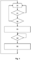
- step S0 The method starts in step S0.
- step S1 a control signal is evaluated which indicates the switching on of a gear pump (500 W maximum consumption). If a transmission pump is not detected, the method returns to start S0. If the addition of a gear pump is recognized, the method continues with step S2.
- step S2 a control signal is evaluated which indicates a critical load on the low-voltage network.
- the control signal is a binary signal generated by the energy management of the motor vehicle, which indicates that there is a critical load or, alternatively, that there is no critical load. If there is no critical load on the low-voltage network, the method returns to start S0. In the event that the gear pump is switched on, the DC / DC converter (2.5kW maximum power) does not provide enough energy or generally not enough energy is available. If there is such a critical load on the low-voltage network, the method continues with step S3.
- step S3 the power consumption of a cooling fan is reduced.
- the electric PWM (pulse width modulated) cooling fan 600W maximum consumption
- the cooling fan is switched off very quickly. Since the cooling system reacts sluggishly when the cooling fan is switched off, the cooler temperature does not increase suddenly after switching off the cooling fan, but only slowly. It is advantageous that this also builds up an induction voltage that provides additional energy. This avoids voltage peaks that would otherwise have a disruptive effect.
- step S4 the control signal, which indicates the connection of a gear pump, is checked to determine whether the gear pump still needs power or not. Once the gear pump has built up the required pressure, it is deactivated again by the engine control so that it no longer consumes electrical power. Step S4 is carried out until it is recognized that the switching on of the gear pump has ended. If it is recognized that the switching on of the gear pump has ended, then the method continues with step S5.
- step S5 the cooling fan is started up again in its previous operating state (100%) by sending a corresponding control signal to the cooling fan.
- the method finally returns to the start S0.
- the high-performance radiator fan is "interlocked" or interconnected with the high performance of the gear pump under certain conditions. At the moment the gear pump is switched on, the cooling fan is reduced to the minimum volume flow for a short time.
- the method can be carried out continuously in an energy management system in order to monitor the occurrence of current peaks and to compensate for such current peaks before they occur by switching off other components accordingly can train. This prevents the low-voltage electrical system from being overloaded.
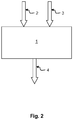
- the energy management system 1 has an interface in order to receive control signals 2, on the basis of which it is determined whether there is a critical load on the low-voltage network.
- control signals 2 can, for example, be parameters of a low-voltage battery which the energy management system 1 receives from a battery manager of the low-voltage battery.
- These control signals 2 can also be sensor data from which the energy management system can determine the current power consumption of various components of the on-board network.
- These control signals 2 can also be the output of power electronics, which inform the energy management system 1, for example, about the operating state of a DC voltage converter.
- the energy management system 1 also has an interface in order to receive a control signal 3, which informs about the connection of a high-current consumer, in particular a gear pump.
- the energy management system 1 can receive such a control signal 3, for example, directly from the respective components, or else from an engine controller.
- the energy management system 1 could also receive several such control signals 3 relating to different high-current consumers.
- the energy management system 1 also has an interface in order to output a control signal 4 which controls the power consumption or current consumption of a component, in this case in particular a cooling fan.
- a control signal 4 which controls the power consumption or current consumption of a component, in this case in particular a cooling fan.
- the cooling fan it can be, for example, a PWM signal with which the frequency of the cooling fan is controlled.
- the energy management system 1 could also receive several such control signals 4 relating to different components.
- the interfaces mentioned can include, for example, a vehicle data bus system and corresponding transmission electronics.
Description
Die Erfindung betrifft ein Bordnetz eines Kraftfahrzeugs, ein Kraftfahrzeug mit einem solchen Bordnetz und ein Verfahren zum Schalten eines Trennelements eines Bordnetzes.The invention relates to an on-board network of a motor vehicle, a motor vehicle with such an on-board network, and a method for switching an isolating element of an on-board network.
Ein Bordnetz eines Fahrzeugs enthält üblicherweise eine Reihe von Bordnetzverbrauchern, einen Starter, einen elektrischen Energiespeicher zum Versorgen der Bordnetzverbraucher und des Starters mit Energie und Trennschalter. Mit Hilfe der Trennschalter können die Bordnetzverbraucher bei einem Start eines Motors eines Fahrzeugs von dem Energiespeicher getrennt werden, um den Starter mit ausreichend Energie zu versorgen.An on-board network of a vehicle usually contains a number of on-board network consumers, a starter, an electrical energy store for supplying the on-board network consumers and the starter with energy and a disconnector. With the help of the isolating switch, the on-board electrical system consumers can be disconnected from the energy store when an engine of a vehicle is started in order to supply the starter with sufficient energy.
In herkömmlichen Bordnetzen können zudem dynamische Verbraucher enthalten sein, deren Betrieb zu Spannungsschwankungen im Bordnetz führen kann. Dadurch kann der Betrieb von Bordnetzverbrauchern, die gegenüber Spannungsschwankungen sensibel sind, gefährdet werden. Diese Spannungsschwankungen werden bisher durch den Einsatz einer Vielzahl an komplexen Bauteilen wie Gleichspannungswandlern (DC/DC-Wandler) und regelbaren Q-Dioden vermieden.Conventional electrical systems can also contain dynamic loads, the operation of which can lead to voltage fluctuations in the electrical system. This can jeopardize the operation of on-board electrical system consumers that are sensitive to voltage fluctuations. These voltage fluctuations have so far been avoided by using a large number of complex components such as direct voltage converters (DC / DC converters) and controllable Q diodes.
In ungünstigen Betriebsfällen werden die Leistungsgrenzen des DC/DC-Spannungswandlers durch eine zu hohe Niedervolt-Bordnetzlast überschritten. Resultierend daraus wird Energie aus der Niedervoltbatterie entnommen, was in einer höheren Belastung durch stärkere Zyklisierung mündet. Im ungünstigsten Fall, z.B. wenn die Batterie entladen ist oder die Batterieklemme nicht verbunden ist, kann ein Bordnetzausfall in Folge von Unterspannung auftreten.In unfavorable operating cases, the performance limits of the DC / DC voltage converter are exceeded due to an excessively high low-voltage electrical system load. As a result, energy is taken from the low-voltage battery, which results in a higher load due to stronger cycling. In the worst case, e.g. If the battery is discharged or the battery terminal is not connected, an on-board network failure can occur as a result of undervoltage.
Gemäß der europäischen Patentanmeldung
Die europäische Patentanmeldung
Die deutsche Offenlegungsschrift die
Die deutsche Offenlegungsschrift
Die deutsche Offenlegungsschrift
Die europäische Patentanmeldung
Aufgabe der vorliegenden Erfindung ist es, ein verbessertes Verfahren zur Steuerung eines Verbrauchers eines Niedervolt-Kraftfahrzeugbordnetzes und eine entsprechend eingerichtete Steuerungsvorrichtung bereitzustellen.The European
The object of the present invention is to provide an improved method for controlling a consumer of a low-voltage motor vehicle electrical system and a correspondingly configured control device.
Diese Aufgabe wird durch das erfindungsgemäße Verfahren nach Anspruch 1 und die Vorrichtung nach Anspruch 10 gelöst.This object is achieved by the method according to the invention according to
Weitere vorteilhafte Ausgestaltungen der Erfindung ergeben sich aus den Unteransprüchen und der folgenden Beschreibung bevorzugter Ausführungsbeispiele der vorliegenden Erfindung.Further advantageous embodiments of the invention emerge from the subclaims and the following description of preferred exemplary embodiments of the present invention.
Im Folgenden werden Ausführungsbeispiele eines Verfahrens zur Steuerung eines Verbrauchers eines Niedervoltbordnetzes eines Kraftfahrzeugs beschrieben, bei dem, wenn ein Zuschalten eines Hochstromverbrauchers erkannt wird, der Stromverbrauch eines anderen Verbrauchers um einen Betrag zurückgenommen wird, der dem Stromverbrauch des Hochstromverbrauchers entspricht.In the following, exemplary embodiments of a method for controlling a consumer of a low-voltage on-board network of a motor vehicle are described, in which, when a high-current consumer is connected, the power consumption of another consumer is reduced by an amount that corresponds to the power consumption of the high-current consumer.
Das Verfahren kann in einem beliebigen Kraftfahrzeug eingesetzt werden, vorzugsweise jedoch in einem Hybridfahrzeug, bei dem ein Niedervoltbordnetz von einem Hochvoltbordnetz über einen Gleichspannungswandler gespeist wird.The method can be used in any motor vehicle, but preferably in a hybrid vehicle in which a low-voltage on-board network is fed from a high-voltage on-board network via a DC voltage converter.
Das Verfahren kann als Steuersoftware implementiert sein, beispielsweise in einem Energiemanager des Kraftfahrzeugs.The method can be implemented as control software, for example in an energy manager of the motor vehicle.
Bei dem Stromverbraucher, dessen Stromverbrauch zurückgenommen wird, kann es sich um einen beliebigen Verbraucher eines Niedervolt-Kraftfahrzeugbordnetzes handeln. Vorteilhafterweise handelt es sich jedoch um einen Verbraucher mit einem ausreichend hohen Stromverbrauch, so dass eine Zurücknahme des Stromverbrauchs des Verbrauchers zu einer nicht unwesentlichen Reduzierung der Gesamtbelastung des Niedervoltbordnetzes führt.The power consumer whose power consumption is reduced can be any consumer of a low-voltage motor vehicle electrical system. Advantageously, however, it is a consumer with a sufficiently high power consumption, so that a reduction in the power consumption of the consumer leads to a not insignificant reduction in the overall load on the low-voltage on-board network.
Besonders vorteilhaft ist es, wenn es sich bei dem Verbraucher, dessen Stromwert zurückgenommen wird, um einen Verbraucher handelt, dessen Wirkung mit Trägheit auf ein Zurücknehmen des Stromwertes reagiert. Damit ist gewährleistet, dass beispielsweise ein sofortiges Abschalten des Verbrauchers nicht unmittelbar zu einer kritischen Beeinträchtigung der Funktionsfähigkeit des gesamten Kraftfahrzeugs führt.It is particularly advantageous if the consumer whose current value is being withdrawn is a consumer whose effect reacts with inertia to a reduction in the current value. This ensures that, for example, switching off the consumer immediately does not lead directly to a critical impairment of the functionality of the entire motor vehicle.
Bei dem Verbraucher, dessen Stromwert zurückgenommen wird, kann es sich beispielsweise um den Kühlerlüfter handeln, denn das Kühlungssystem weist eine gewisse Trägheit auf. Wird der Kühlerlüfter spontan abgeschaltet, führt dies nicht unmittelbar zu einer Überhitzung des Motors. Vielmehr steigt die Temperatur des Kühlungssystems nach Abschalten des Kühlerlüfters nur langsam an.The consumer whose current value is being withdrawn can, for example, be the cooling fan, because the cooling system exhibits a certain inertia. If the radiator fan is switched off spontaneously, this does not immediately lead to the engine overheating. Rather, the temperature of the cooling system rises only slowly after the cooling fan has been switched off.
Besonders vorteilhaft ist es, wenn der Verbraucher, dessen Stromwert zurückgenommen wird, eine Induktivität aufweist, so dass bei Zurücknehmen des Stromwertes des Verbrauchers eine Induktionsspannung generiert wird, welche das Niedervoltbordnetz zusätzlich speist. Dies hat den Vorteil, dass durch Herunterfahren des Verbrauchers nicht nur die Stromentnahme des Verbrauchers reduziert wird, sondern dem Niedervoltbordnetz in Momenten von Stromentnahmespitzen sogar zusätzliche Leistung zugeführt werden kann.It is particularly advantageous if the consumer whose current value is withdrawn has an inductance, so that when the consumer current value is withdrawn, an induction voltage is generated which additionally feeds the low-voltage electrical system. This has the advantage that by shutting down the consumer, not only is the consumer's current consumption reduced, but additional power can even be supplied to the low-voltage on-board network in moments of current consumption peaks.
Bei dem Hochstromverbraucher kann es sich um einen beliebigen Verbraucher eines Niedervolt-Kraftfahrzeugbordnetzes handeln. Der Begriff Hochstromverbraucher ist hier so zu verstehen, dass der Stromverbrauch des Hochstromverbrauchers für die Belastung des Bordnetzes nicht unwesentlich ist, d.h. z.B. in kritischen Betriebszuständen ein Hinzuschalten des Hochstromverbrauchers etwaige ungünstige Auswirkungen auf die Betriebssituation wie beispielsweise einen Zusammenbruch der Niedervoltspannung oder einen Ausfall eines das Niedervoltnetz speisenden Gleichspannungswandlers mit sich bringen könnte.The high-current consumer can be any consumer of a low-voltage motor vehicle electrical system. The term high-current consumer is to be understood here in such a way that the power consumption of the high-current consumer is not insignificant for the load on the vehicle electrical system, i.e. e.g. In critical operating states, switching on the high-current consumer could have any adverse effects on the operating situation, such as a collapse of the low-voltage voltage or a failure of a DC-DC converter feeding the low-voltage network.
Vorzugsweise handelt es sich bei dem Hochstromverbraucher um einen Verbraucher, der nur kurzzeitig zugeschaltet wird. Dies hat den Vorteil, dass durch Hinzuschalten des Hochstromverbrauchers nur kurzfristige Stromspitzen entstehen, die durch zeitlich beschränktes Abschalten eines anderen Verbrauchers vorübergehend kompensiert werden können.The high-current consumer is preferably a consumer that is only switched on for a short time. This has the advantage that switching on the high-current consumer only results in short-term current peaks which can be temporarily compensated for by temporarily switching off another consumer.
Bei dem Hochstromverbraucher kann es sich beispielsweise um eine Getriebepumpe (bzw. eine Ölpumpe) handeln, die für den normalen Schaltbetrieb und/oder zur Kühlung verwendet wird. Eine solche Getriebepumpe wird in bestimmten Betriebszuständen lediglich kurzfristig aktiviert, so dass eine durch Aktivierung der Getriebepumpe bewirkte Stromspitze durch ein zeitlich beschränktes Abschalten eines anderen Verbrauchers, wie beispielsweise einem Kühlerlüfter, vorübergehend kompensiert werden kann.The high-current consumer can be, for example, a gear pump (or an oil pump) that is used for normal switching operation and / or for cooling. Such a gear pump is only activated for a short time in certain operating states, so that a current peak caused by activation of the gear pump can be temporarily compensated for by temporarily switching off another consumer, such as a cooling fan.
Die vorliegende Erfindung ermöglicht es demnach, verschiedene Verbraucher miteinander zu betrachten, mithin verschiedene Verbraucher zu "verschränken" bzw. zu verschalten. Beispielsweise wird der Kühlerlüfter mit hoher Leistung unter bestimmten Bedingungen gegen die hohe Leistung der Getriebepumpe "verschränkt" bzw. verschaltet. Im Moment des Einschaltens der Getriebepumpe wird für kurze Zeit der Kühlerlüfter auf den minimalsten Volumenstrom reduziert. Hierbei wird die Trägheit des Kühlungssystems ausgenutzt. Hat die Getriebepumpe den erforderlichen Druck aufgebaut, kann der Kühlerlüfter sofort wieder hochdrehen.The present invention accordingly makes it possible to consider different consumers with one another, and consequently to "interconnect" or interconnect different consumers. For example, the high-performance radiator fan is "interlocked" or interconnected with the high performance of the gear pump under certain conditions. At the moment the gear pump is switched on, the cooling fan is reduced to the minimum volume flow for a short time. The inertia of the cooling system is used here. Once the gear pump has built up the required pressure, the radiator fan can rev up again immediately.
Bei dem Verfahren wird vorteilhafter Weise ein Steuersignal ausgewertet, welches eine kritische Belastung des Niedervoltnetzes anzeigt und wobei der Stromverbrauch des anderen Verbrauchers zurückgenommen wird, falls das Steuersignal eine kritische Belastung des Niedervoltnetzes anzeigt. Insbesondere kann das Steuersignal anzeigen, dass viele Verbraucher Energie benötigen. Das Steuersignal kann beispielsweise auch erzeugt werden, wenn zu viel Energie aus einer Niedervoltbatterie entnommen wird, insbesondere wenn die Batterie nicht mehr genug Energie enthält, um eine stabile Versorgung des Niedervoltbordnetzes zu gewährleisten. Alternativ kann das Steuersignal auch erzeugt werden, wenn eine Stromentnahme aus einem Hochvoltbordnetz einen kritischen Wert überschreitet. In die Erzeugung des Steuersignals kann beispielsweise auch einfließen, ob der Verbrennungsmotor unter Volllast (z.B. Bergauf, viel Gewicht u./o. Anhänger) betrieben wird.In the method, a control signal is advantageously evaluated which indicates a critical load on the low-voltage network and the power consumption of the other consumer is reduced if the control signal indicates a critical load on the low-voltage network. In particular, the control signal can indicate that many consumers require energy. The control signal can also be generated, for example, if too much energy is drawn from a low-voltage battery, in particular if the battery no longer contains enough energy to ensure a stable supply of the low-voltage on-board network. Alternatively, the control signal can also be generated when a current drawn from a high-voltage on-board network exceeds a critical value. The generation of the control signal can also include, for example, whether the combustion engine is operated at full load (e.g. uphill, heavy weight and / or trailer).
Das Steuersignal kann auch auf Basis einer Kombination der genannten Faktoren bestimmt werden. Das Steuersignal kann beispielsweise von einer Energiemanagement-Einheit des Kraftfahrzeugs, von einem Batteriemanager oder von einer Leistungselektronik erzeugt werden.The control signal can also be determined based on a combination of the factors mentioned. The control signal can be generated, for example, by an energy management unit of the motor vehicle, by a battery manager or by power electronics.
Ferner kann bei dem Verfahren ein Steuersignal ausgewertet werden, welches über die Zuschaltung des Hochstromverbrauchers informiert. Bei dem Steuersignal kann es sich beispielsweise um ein Signal der Motorsteuerung handeln, das einen Verbraucher wie eine Getriebepumpe aktiviert. Das Steuerverfahren der vorliegenden Erfindung kann beispielsweise den Signalfluss einer Motorsteuerung auf das Auftreten des Steuersignals überwachen. Dies hat den Vorteil, dass für die Implementierung des erfindungsgemäßen Verfahrens kein wesentlicher Eingriff in die Motorsteuerung erfolgen muss.Furthermore, in the method, a control signal can be evaluated, which provides information about the connection of the high-current consumer. The control signal can be, for example, a signal from the engine control that activates a consumer such as a gear pump. The control method of the present invention can, for example, monitor the signal flow of an engine controller for the occurrence of the control signal. This has the advantage that the implementation of the method according to the invention does not require any major intervention in the engine control.
Nach Erkennen des Steuersignals, welches über die Zuschaltung des Hochstromverbrauchers informiert, wird vorteilhafter Weise der Stromverbrauch des anderen Verbrauchers maximal zurückgenommen. Liegt beispielsweise der Leistungsverbrauch einer Getriebepumpe bei maximaler Belastung bei 500 W und der Leistungsverbrauch eines Kühlerlüfters bei 600 W, so kann durch komplettes Zurückfahren des Stromverbrauchs des Kühlerlüfters eine von der Getriebepumpe erzeugte Belastungsspitze kurzfristig kompensiert werden.After the control signal, which informs about the connection of the high-current consumer, has been recognized, the current consumption of the other consumer is advantageously reduced to a maximum. For example, if the power consumption of a gear pump at maximum load is 500 W and the power consumption of a cooling fan is 600 W, a load peak generated by the gear pump can be compensated for briefly by completely reducing the power consumption of the cooling fan.
Alternativ wird nach Erkennen des Steuersignals, welches über die Zuschaltung des Hochstromverbrauchers informiert, der Stromverbrauch des anderen Verbrauchers um einen Betrag zurückgenommen, der im Wesentlichen dem Stromverbrauch des Hochstromverbrauchers entspricht. Dazu können im Energiemanagement des Kraftfahrzeugs typische Leistungswerte der Verbraucher hinterlegt werden. Handelt es sich bei dem zurückzunehmenden Verbraucher beispielsweise um einen PWM-Kühlerlüfter, so kann dieser per Pulsweitenmodulation differenziert angesteuert werden, so dass der Stromverbrauch eingestellt werden kann. Dies hat den Vorteil, dass die Summe der Leistung nahezu konstant bleibt, bzw. bei induktiven Verbrauchern sogar geringer werden kann.Alternatively, after the detection of the control signal, which informs about the connection of the high-current consumer, the power consumption of the other consumer is reduced by an amount which essentially corresponds to the power consumption of the high-current consumer. This can be done in the energy management of the motor vehicle typical performance values of the consumers are stored. If the consumer to be withdrawn is, for example, a PWM cooling fan, it can be controlled differently by pulse width modulation so that the power consumption can be adjusted. This has the advantage that the sum of the power remains almost constant or, in the case of inductive loads, can even be lower.
Die vorliegende Erfindung betrifft auch eine Steuerungsvorrichtung für ein Kraftfahrzeug, die dazu ausgelegt ist, die oben beschriebenen Verfahren auszuführen. Bei der Steuerungsvorrichtung kann es sich beispielsweise um ein Energiemanagement-System eines Kraftfahrzeugs handeln. Die Steuerungsvorrichtung kann als ein Prozessor ausgeführt sein, auf dem Software ausgeführt wird, welche die oben beschriebenen Verfahren ausführt.The present invention also relates to a control device for a motor vehicle which is designed to carry out the methods described above. The control device can be, for example, an energy management system of a motor vehicle. The control device can be embodied as a processor on which software is executed that executes the methods described above.
Ausführungsbeispiele der Erfindung werden nun beispielhaft und unter Bezugnahme auf die beigefügten Zeichnungen beschrieben, wobei:
-
Fig. 1 schematisch ein Ausführungsbeispiel des Verfahrens zur Steuerung von Verbrauchern eines Niedervoltbordnetzes eines Kraftfahrzeugs zeigt; und -
Fig. 2 schematisch eine Steuervorrichtung zur Steuerung von Verbrauchern eines Niedervoltbordnetzes eines Kraftfahrzeugs zeigt.
-
Fig. 1 schematically shows an embodiment of the method for controlling loads of a low-voltage electrical system of a motor vehicle; and -
Fig. 2 schematically shows a control device for controlling consumers of a low-voltage electrical system of a motor vehicle.
Bezugnehmend auf das Steuerungsverfahren der
Das Verfahren startet in Schritt S0.Referring to the control method of the
The method starts in step S0.
In Schritt S1 wird ein Steuersignal ausgewertet, welches das Hinzuschalten einer Getriebepumpe (500 W Maximalverbrauch) anzeigt. Wird kein Hinzuschalten einer Getriebepumpe erkannt, so kehrt das Verfahren zum Start S0 zurück. Wird ein Hinzuschalten einer Getriebepumpe erkannt, so fährt das Verfahren mit Schritt S2 fort.In step S1, a control signal is evaluated which indicates the switching on of a gear pump (500 W maximum consumption). If a transmission pump is not detected, the method returns to start S0. If the addition of a gear pump is recognized, the method continues with step S2.
In Schritt S2 wird ein Steuersignal ausgewertet, welches eine kritische Belastung des Niedervoltnetzes anzeigt. Bei dem Steuersignal handelt es sich um ein vom Energiemanagement des Kraftfahrzeugs erzeugtes binäres Signal, welches anzeigt, dass eine kritische Belastung vorliegt, oder, alternativ, dass keine kritische Belastung vorliegt.
Liegt keine kritische Belastung des Niedervoltnetzes vor, so kehrt das Verfahren zum Start S0 zurück. Für den Fall des Einschaltens der Getriebepumpe kann es vorkommen, dass der DC/DC Wandler (2,5kW Maximalleistung) nicht genug Energie bereitstellt oder allg. nicht genug Energie vorhanden ist. Liegt solch eine kritische Belastung des Niedervoltnetzes vor, so fährt das Verfahren mit Schritt S3 fort.In step S2, a control signal is evaluated which indicates a critical load on the low-voltage network. The control signal is a binary signal generated by the energy management of the motor vehicle, which indicates that there is a critical load or, alternatively, that there is no critical load.
If there is no critical load on the low-voltage network, the method returns to start S0. In the event that the gear pump is switched on, the DC / DC converter (2.5kW maximum power) does not provide enough energy or generally not enough energy is available. If there is such a critical load on the low-voltage network, the method continues with step S3.
In Schritt S3 wird der Stromverbrauch eines Kühlerlüfters zurückgenommen. Hier wird insbesondere der elektrische PWM (PulsWeitenModulierte) Kühlerlüfter (600W Maximalverbrauch) sehr schnell von 100% auf 0 heruntergetaktet oder auf minimalsten Volumenstrom reduziert, indem ein entsprechendes Steuersignal an den Kühlerlüfter gesendet wird. Es erfolgt damit ein sehr schnelles Abschalten des Kühlerlüfters. Da das Kühlersystem mit Trägheit auf ein Abschalten des Kühlerlüfters reagiert, nimmt die Kühlertemperatur nach Abschalten des Kühlerlüfters nicht sprunghaft, sondern nur langsam zu. Vorteilhaft ist, dass dadurch auch noch eine Induktionsspannung aufgebaut wird, die zusätzlich Energie bereit stellt. Dadurch werden Spannungsspitzen vermieden, die sich ansonsten störend auswirken.In step S3, the power consumption of a cooling fan is reduced. In particular, the electric PWM (pulse width modulated) cooling fan (600W maximum consumption) is clocked down very quickly from 100% to 0 or reduced to the minimum volume flow by sending a corresponding control signal to the cooling fan. This means that the cooling fan is switched off very quickly. Since the cooling system reacts sluggishly when the cooling fan is switched off, the cooler temperature does not increase suddenly after switching off the cooling fan, but only slowly. It is advantageous that this also builds up an induction voltage that provides additional energy. This avoids voltage peaks that would otherwise have a disruptive effect.
In Schritt S4 wird das Steuersignal, welches das Hinzuschalten einer Getriebepumpe anzeigt, daraufhin überprüft, ob die Getriebepumpe noch Strom benötigt, oder nicht. Hat die Getriebepumpe den erforderlichen Druck aufgebaut, so wird sie von der Motorsteuerung wieder deaktiviert, so dass sie keine elektrische Leistung mehr verbraucht. Schritt S4 wird so lange ausgeführt, bis erkannt wird, dass das Hinzuschalten der Getriebepumpe beendet ist. Wird erkannt wird, dass das Hinzuschalten der Getriebepumpe beendet ist, dann fährt das Verfahren mit Schritt S5 fort.In step S4, the control signal, which indicates the connection of a gear pump, is checked to determine whether the gear pump still needs power or not. Once the gear pump has built up the required pressure, it is deactivated again by the engine control so that it no longer consumes electrical power. Step S4 is carried out until it is recognized that the switching on of the gear pump has ended. If it is recognized that the switching on of the gear pump has ended, then the method continues with step S5.
In Schritt S5 wird der Kühlerlüfter wieder in seinen vorigen Betriebszustand (100%) hochgefahren, indem ein entsprechendes Steuersignal an den Kühlerlüfter gesendet.In step S5, the cooling fan is started up again in its previous operating state (100%) by sending a corresponding control signal to the cooling fan.
Das Verfahren kehrt schließlich zum Start S0 zurück.The method finally returns to the start S0.
In diesem Ausführungsbeispiel wird der Kühlerlüfter mit hoher Leistung unter bestimmten Bedingungen gegen die hohe Leistung der Getriebepumpe "verschränkt" bzw. verschaltet. Im Moment des Einschaltens der Getriebepumpe wird für kurze Zeit der Kühlerlüfter auf minimalsten Volumenstrom reduziert.In this exemplary embodiment, the high-performance radiator fan is "interlocked" or interconnected with the high performance of the gear pump under certain conditions. At the moment the gear pump is switched on, the cooling fan is reduced to the minimum volume flow for a short time.
Das Verfahren kann auf diese Weise in einem Energiemanagement-System ständig ausgeführt werden, um das Auftreten von Stromspitzen zu überwachen und durch entsprechendes Abschalten anderer Komponenten solche Stromspitzen zu kompensieren, bevor sie sich ausbilden können. Dadurch kann eine Überlastung des Niedervoltbordnetzes verhindert werden.In this way, the method can be carried out continuously in an energy management system in order to monitor the occurrence of current peaks and to compensate for such current peaks before they occur by switching off other components accordingly can train. This prevents the low-voltage electrical system from being overloaded.
Bezugnehmend auf die Steuervorrichtung der
Das Energiemanagement-System 1 weist eine Schnittstelle auf, um Steuersignale 2 entgegenzunehmen, auf deren Basis ermittelt wird, ob eine kritische Belastung des Niedervoltnetzes vorliegt. Bei diesen Steuersignalen 2 kann es sich beispielsweise um Parameter einer Niedervoltbatterie handeln, welche das Energiemanagement-System 1 von einem Batteriemanager der Niedervoltbatterie erhält. Bei diesen Steuersignalen 2 kann es sich ferner um Sensordaten handeln, aus welchen das Energiemanagement-System den aktuellen Stromverbrauch verschiedenster Komponenten des Bordnetzes ermitteln kann. Bei diesen Steuersignalen 2 kann es sich ferner um die Ausgabe einer Leistungselektronik handeln, welche das Energiemanagement-System 1 beispielsweise über den Betriebszustand eines Gleichspannungswandlers informiert.Referring to the control device of
The
Das Energiemanagement-System 1 weist ferner eine Schnittstelle auf, um ein Steuersignal 3 entgegenzunehmen, welches über die Zuschaltung eines Hochstromverbrauchers, insbesondere einer Getriebepumpe informiert. Das Energiemanagement-System 1 kann solch ein Steuersignal 3 beispielsweise direkt von der jeweiligen Komponenten erhalten, oder aber auch von einer Motorsteuerung. Das Energiemanagement-System 1 könnte auch mehrere solche Steuersignale 3 betreffend unterschiedliche Hochstromverbraucher entgegennehmen.The
Das Energiemanagement-System 1 weist ferner eine Schnittstelle auf, um ein Steuersignal 4 auszugeben, welches den Leistungsverbrauch bzw. Stromverbrauch einer Komponente, hier insbesondere eines Kühlerlüfters steuert. Im Falle des Kühlerlüfters kann es sich beispielsweise um ein PWM-Signal handeln, mit dem die Frequenz des Kühlerlüfters gesteuert wird. Das Energiemanagement-System 1 könnte auch mehrere solche Steuersignale 4 betreffend unterschiedliche Komponenten entgegennehmen.The
Die genannten Schnittstellen können beispielsweise ein Fahrzeugdatenbussystem und entsprechende Übertragungselektronik umfassen.The interfaces mentioned can include, for example, a vehicle data bus system and corresponding transmission electronics.
Soweit im vorstehenden auf ein Energiemanagement-System und eine Motorsteuerung abgestellt wurde, wird der Fachmann erkennen, dass die Funktionalität dieser Steuerungen in einem Prozessor realisiert werden kann und als Software implementiert werden kann. Die Funktionalität muss nicht notwendiger Weise auf zwei getrennte Hardware-Einheiten separiert sein. Vielmehr kann die Funktionalität auch in einem zentralen Fahrzeugprozessor realisiert werden, oder auch als verteiltes System, das über mehrere Komponenten verteilt ist.As far as the above focus on an energy management system and an engine control, the person skilled in the art will recognize that the functionality of these controls can be realized in a processor and can be implemented as software. The Functionality does not necessarily have to be separated on two separate hardware units. Rather, the functionality can also be implemented in a central vehicle processor, or as a distributed system that is distributed over several components.
Ferner wird der Fachmann erkennen, dass die in den Ausführungsbeispielen angegebene Reihenfolge von Schritten nicht zwingend ist. So können beispielsweise in dem Ausführungsbeispiel der
- 11
- Energiemanagement-SystemEnergy management system
- 22
- Steuersignale zur Ermittlung einer kritischen Belastung des NiedervoltnetzesControl signals for determining a critical load on the low-voltage network
- 33
- Steuersignal welches über die Zuschaltung eines Hochstromverbrauchers informiertControl signal which informs about the connection of a high-current consumer
- 44th
- Steuersignal welches den Leistungsverbrauch einer Komponente steuertControl signal that controls the power consumption of a component
- S0S0
- Startbegin
- S1S1
- Erkennen des Hinzuschaltens einer GetriebepumpeDetection of switching on a gear pump
- S2S2
- Überprüfen auf eine kritische Belastung des NiedervoltnetzesCheck for a critical load on the low-voltage network
- S3S3
- Zurücknehmen des Stromverbrauchs eines KühlerlüftersReduce the power consumption of a cooling fan
- S4S4
- Überprüfen, ob das Hinzuschalten der Getriebepumpe beendet istCheck whether the connection of the gear pump has been completed
- S5S5
- Hochfahren des KühlerlüftersStarting up the cooling fan
Claims (9)
- Method for controlling a load of a low-voltage electrical system of a motor vehicle, in which, when a connection of a high-current load is detected (S1), the current consumption of a radiator fan is reduced by an amount (S3) corresponding to the current consumption of the high-current load.
- Method according to claim 1, wherein the load whose current value is reduced is a PWM radiator fan which is driven differentially by pulse width modulation so that the current consumption can be adjusted.
- Method according to any one of the preceding claims, wherein the load whose current value is reduced is a load whose action reacts with inertia to a reduction in the current value.
- Method according to any one of the preceding claims, wherein the load has an inductance so that, upon reduction of the current value of the load, an induction voltage is generated which additionally supplies the low-voltage electrical system.
- Method according to any one of the preceding claims, and wherein the high-current load is a gear pump.
- Method according to any one of the preceding claims, in which a control signal is evaluated (S2) which indicates a critical utilization of the low-voltage network, and wherein the current consumption of the other load is reduced if the control signal indicates a critical utilization of the low-voltage network.
- Method according to any one of the preceding claims, wherein a control signal which informs about the connection of the high-current load is evaluated (S1).
- Method according to any one of the preceding claims, wherein, after detecting the control signal which informs about the connection of the high-current load, the current consumption of the other load is maximally reduced (S3).
- Control device (1) and radiator fan for a motor vehicle, wherein the control device is designed to execute the method according to any one of the preceding claims.
Applications Claiming Priority (2)
| Application Number | Priority Date | Filing Date | Title |
|---|---|---|---|
| DE102015202453.9A DE102015202453A1 (en) | 2015-02-11 | 2015-02-11 | Method for controlling a consumer of a low-voltage on-board electrical system |
| PCT/EP2016/052683 WO2016128375A1 (en) | 2015-02-11 | 2016-02-09 | Method for controlling a load of a low-voltage vehicle electrical system |
Publications (2)
| Publication Number | Publication Date |
|---|---|
| EP3256347A1 EP3256347A1 (en) | 2017-12-20 |
| EP3256347B1 true EP3256347B1 (en) | 2020-08-26 |
Family
ID=55411356
Family Applications (1)
| Application Number | Title | Priority Date | Filing Date |
|---|---|---|---|
| EP16706147.2A Active EP3256347B1 (en) | 2015-02-11 | 2016-02-09 | Method for controlling a load of a low-voltage vehicle electrical system |
Country Status (5)
| Country | Link |
|---|---|
| US (1) | US10479299B2 (en) |
| EP (1) | EP3256347B1 (en) |
| CN (1) | CN107000662B (en) |
| DE (1) | DE102015202453A1 (en) |
| WO (1) | WO2016128375A1 (en) |
Families Citing this family (2)
| Publication number | Priority date | Publication date | Assignee | Title |
|---|---|---|---|---|
| CN213948661U (en) * | 2020-11-13 | 2021-08-13 | 赛格威科技有限公司 | All-terrain vehicle power supply system and all-terrain vehicle |
| CN214084584U (en) * | 2020-11-13 | 2021-08-31 | 赛格威科技有限公司 | All-terrain vehicle power supply system and all-terrain vehicle |
Citations (1)
| Publication number | Priority date | Publication date | Assignee | Title |
|---|---|---|---|---|
| WO2007141069A1 (en) * | 2006-06-07 | 2007-12-13 | Robert Bosch Gmbh | Power coordinator for an electrical system |
Family Cites Families (25)
| Publication number | Priority date | Publication date | Assignee | Title |
|---|---|---|---|---|
| DE2324457A1 (en) | 1973-05-11 | 1974-11-21 | Licentia Gmbh | PROCEDURE AND ARRANGEMENT FOR OPERATION MONITORING OF ELECTRIC MULTI-MOTOR DRIVES |
| DE3142913A1 (en) | 1981-10-29 | 1983-05-11 | Herbert Prof. Dr.-Ing. 3300 Braunschweig Weh | Electrical machine having an annular winding armature and permanently excited rotors |
| EP0601300B1 (en) | 1992-12-05 | 1995-12-13 | Volkswagen Aktiengesellschaft | Driving condition dependent switching of electrical consumers in a motor vehicle |
| DE19709317B4 (en) | 1997-03-07 | 2008-04-30 | Robert Bosch Gmbh | Method and device for controlling a vehicle |
| DE19931144B9 (en) * | 1998-09-08 | 2013-02-07 | Volkswagen Ag | Method for operating an electrical vehicle electrical system |
| DE19857916A1 (en) * | 1998-12-15 | 2000-06-21 | Bosch Gmbh Robert | Method and device for controlling electrical consumers in a vehicle |
| WO2001000485A1 (en) | 1999-06-24 | 2001-01-04 | Siemens Aktiengesellschaft | Propelling and driving system for boats |
| JP3624831B2 (en) | 2000-12-28 | 2005-03-02 | 株式会社デンソー | Vehicle power supply device and engine drive regulation support device |
| DE50211256D1 (en) | 2001-08-15 | 2008-01-03 | Bosch Gmbh Robert | STABILIZATION OF A PORTION NETWORK THROUGH GENERATION OF SHORT-TERM AVAILABLE ENERGY |
| DE10164463B4 (en) * | 2001-11-26 | 2017-04-27 | Volkswagen Ag | Method and device for vehicle electrical system management in a motor vehicle |
| DE10233822A1 (en) | 2002-07-25 | 2004-02-26 | Daimlerchrysler Ag | Determining mass of gas drawn into fuel cell system by compressor, e.g. in electric vehicle, involves measuring where uneven gas flow caused by compressor operation is practically negligible in effect on fuel cell operation |
| EP1405767A1 (en) * | 2002-10-02 | 2004-04-07 | Ford Global Technologies, Inc., A subsidiary of Ford Motor Company | Boardnet for a vehicle |
| DE10252292A1 (en) * | 2002-11-11 | 2004-06-09 | Siemens Ag | Method for controlling the energy distribution in a means of transport and means of transport that implements this method |
| DE10312553B3 (en) | 2003-03-21 | 2004-07-22 | Audi Ag | Automobile with several control devices switched between active and inactive conditions and central monitoring control device providing watch-dog function |
| DE10336815A1 (en) * | 2003-08-11 | 2005-03-10 | Bosch Gmbh Robert | Apparatus for controlling an electric load in terms of energy management whereby current consumption is controlled depending on the cycle of a pulse width modulated signal |
| ES2295715T3 (en) * | 2004-02-16 | 2008-04-16 | Catem Develec Gmbh | ELECTRIC CIRCUIT FOR VEHICLES WITH ACCUMULATION OF CURRENT OF THE GENERATOR INDEPENDENT OF THE BATTERY. |
| DE102004038741A1 (en) * | 2004-08-10 | 2006-02-23 | Robert Bosch Gmbh | Method for managing the energy consumption of electrical consumers in an electrical network |
| DE102005047011A1 (en) * | 2005-09-30 | 2007-04-05 | Ford Global Technologies, LLC, Dearborn | Electrical energy control device for motor vehicle, has supply control unit to control system parameters, which influence energy generation, and distribution control unit to control distribution of total energy on loads of power supply |
| DE102005057306B4 (en) * | 2005-12-01 | 2017-01-05 | Bayerische Motoren Werke Aktiengesellschaft | Method and device for stabilizing a DC electrical system |
| JP4618277B2 (en) | 2007-07-24 | 2011-01-26 | 株式会社デンソー | Power management system |
| WO2012163421A1 (en) | 2011-06-01 | 2012-12-06 | Siemens Aktiengesellschaft | Assignment of power or current strength to charging devices |
| ITTO20110893A1 (en) * | 2011-10-06 | 2013-04-07 | Alenia Aeronautica Spa | SYSTEM AND METHOD OF AUTOMATIC MANAGEMENT OF ELECTRIC POWER FOR AERONAUTICAL APPLICATIONS |
| DE102011089085A1 (en) | 2011-12-19 | 2013-06-20 | Robert Bosch Gmbh | Method and device for power management of an electric drive for a hybrid vehicle |
| DE102012222208B4 (en) * | 2012-12-04 | 2021-03-18 | Vitesco Technologies GmbH | Method for the controlled connection of several on-board network branches of a vehicle, control unit for executing the method and on-board network |
| US20140244107A1 (en) * | 2013-02-28 | 2014-08-28 | C.E. Niehoff & Co. | Battery charge voltage compensating system and method of operation |
-
2015
- 2015-02-11 DE DE102015202453.9A patent/DE102015202453A1/en not_active Withdrawn
-
2016
- 2016-02-09 CN CN201680004213.9A patent/CN107000662B/en active Active
- 2016-02-09 EP EP16706147.2A patent/EP3256347B1/en active Active
- 2016-02-09 WO PCT/EP2016/052683 patent/WO2016128375A1/en active Application Filing
-
2017
- 2017-07-29 US US15/663,705 patent/US10479299B2/en active Active
Patent Citations (1)
| Publication number | Priority date | Publication date | Assignee | Title |
|---|---|---|---|---|
| WO2007141069A1 (en) * | 2006-06-07 | 2007-12-13 | Robert Bosch Gmbh | Power coordinator for an electrical system |
Also Published As
| Publication number | Publication date |
|---|---|
| EP3256347A1 (en) | 2017-12-20 |
| CN107000662A (en) | 2017-08-01 |
| CN107000662B (en) | 2020-10-09 |
| US20170327063A1 (en) | 2017-11-16 |
| DE102015202453A1 (en) | 2016-08-11 |
| WO2016128375A1 (en) | 2016-08-18 |
| US10479299B2 (en) | 2019-11-19 |
Similar Documents
| Publication | Publication Date | Title |
|---|---|---|
| DE102014203030B4 (en) | Method for the controlled connection of several on-board network branches of a vehicle, control unit for executing the method and vehicle on-board network | |
| EP1784910B1 (en) | Voltage regulator with over-voltage protection | |
| EP2953227A1 (en) | Electrical system for a motor vehicle | |
| EP2996898B1 (en) | Drive unit for controlling an engine | |
| WO2014086651A2 (en) | Method for the controlled connection of a plurality of on-board power system branches of a vehicle, control unit for carrying out the method and on-board power system | |
| DE102013200763A1 (en) | SYSTEM AND METHOD FOR VEHICLE ENERGY MANAGEMENT | |
| EP3320204B1 (en) | Integration of starter current control and on-board electrical system disconnector switch | |
| DE102012206932A1 (en) | Motor vehicle electrical system with at least two subnets | |
| EP3116752A1 (en) | Arrangement for supplying electrical energy to a motor vehicle | |
| DE102016202638A1 (en) | Voltage converter device | |
| WO2013143847A2 (en) | Energy storing device with cooling elements, and method for cooling energy storing cells | |
| DE102008039284A1 (en) | Electrical-on board power supply operating method for motor vehicle, involves connecting or separating power system and energy system in dependent of function of operating conditions | |
| DE102014105106A1 (en) | Intelligent power distribution unit | |
| EP2840253B1 (en) | On-board electrical system of a motor vehicle and vehicle with such an on-board electrical system | |
| DE112017006219B4 (en) | Vehicle mounted power supply device | |
| DE102007005571B4 (en) | Increased availability fan assembly and method of its operation | |
| EP3256347B1 (en) | Method for controlling a load of a low-voltage vehicle electrical system | |
| DE102014105040B4 (en) | Device and method for stabilizing vehicle voltage | |
| WO2017016746A1 (en) | Method for operating a multi-phase direct voltage converter | |
| WO2014121995A2 (en) | Method for operating an energy supply unit for an on-board power system of a motor vehicle | |
| DE102008012640A1 (en) | Device for coupling several subnetworks | |
| WO2013107560A1 (en) | On-board electrical system having a d.c. converter, control device, and associated operating method | |
| DE10321872A1 (en) | Generator control with main and auxiliary controller | |
| DE102010021402A1 (en) | Electrical system for motor car, has reverse polarity protection device connected in series to energy storage unit and formed to prevent current flow due to battery attached with wrong polarity to electrical system | |
| DE102015212623A1 (en) | Method for operating parallel-connected generator units |
Legal Events
| Date | Code | Title | Description |
|---|---|---|---|
| STAA | Information on the status of an ep patent application or granted ep patent |
Free format text: STATUS: THE INTERNATIONAL PUBLICATION HAS BEEN MADE |
|
| PUAI | Public reference made under article 153(3) epc to a published international application that has entered the european phase |
Free format text: ORIGINAL CODE: 0009012 |
|
| STAA | Information on the status of an ep patent application or granted ep patent |
Free format text: STATUS: REQUEST FOR EXAMINATION WAS MADE |
|
| 17P | Request for examination filed |
Effective date: 20170911 |
|
| AK | Designated contracting states |
Kind code of ref document: A1 Designated state(s): AL AT BE BG CH CY CZ DE DK EE ES FI FR GB GR HR HU IE IS IT LI LT LU LV MC MK MT NL NO PL PT RO RS SE SI SK SM TR |
|
| AX | Request for extension of the european patent |
Extension state: BA ME |
|
| DAV | Request for validation of the european patent (deleted) | ||
| DAX | Request for extension of the european patent (deleted) | ||
| STAA | Information on the status of an ep patent application or granted ep patent |
Free format text: STATUS: EXAMINATION IS IN PROGRESS |
|
| 17Q | First examination report despatched |
Effective date: 20190503 |
|
| GRAP | Despatch of communication of intention to grant a patent |
Free format text: ORIGINAL CODE: EPIDOSNIGR1 |
|
| STAA | Information on the status of an ep patent application or granted ep patent |
Free format text: STATUS: GRANT OF PATENT IS INTENDED |
|
| INTG | Intention to grant announced |
Effective date: 20200312 |
|
| GRAS | Grant fee paid |
Free format text: ORIGINAL CODE: EPIDOSNIGR3 |
|
| GRAA | (expected) grant |
Free format text: ORIGINAL CODE: 0009210 |
|
| STAA | Information on the status of an ep patent application or granted ep patent |
Free format text: STATUS: THE PATENT HAS BEEN GRANTED |
|
| AK | Designated contracting states |
Kind code of ref document: B1 Designated state(s): AL AT BE BG CH CY CZ DE DK EE ES FI FR GB GR HR HU IE IS IT LI LT LU LV MC MK MT NL NO PL PT RO RS SE SI SK SM TR |
|
| REG | Reference to a national code |
Ref country code: GB Ref legal event code: FG4D Free format text: NOT ENGLISH |
|
| REG | Reference to a national code |
Ref country code: CH Ref legal event code: EP |
|
| REG | Reference to a national code |
Ref country code: DE Ref legal event code: R096 Ref document number: 502016010944 Country of ref document: DE |
|
| REG | Reference to a national code |
Ref country code: AT Ref legal event code: REF Ref document number: 1306076 Country of ref document: AT Kind code of ref document: T Effective date: 20200915 |
|
| REG | Reference to a national code |
Ref country code: IE Ref legal event code: FG4D Free format text: LANGUAGE OF EP DOCUMENT: GERMAN |
|
| REG | Reference to a national code |
Ref country code: LT Ref legal event code: MG4D |
|
| PG25 | Lapsed in a contracting state [announced via postgrant information from national office to epo] |
Ref country code: NO Free format text: LAPSE BECAUSE OF FAILURE TO SUBMIT A TRANSLATION OF THE DESCRIPTION OR TO PAY THE FEE WITHIN THE PRESCRIBED TIME-LIMIT Effective date: 20201126 Ref country code: GR Free format text: LAPSE BECAUSE OF FAILURE TO SUBMIT A TRANSLATION OF THE DESCRIPTION OR TO PAY THE FEE WITHIN THE PRESCRIBED TIME-LIMIT Effective date: 20201127 Ref country code: FI Free format text: LAPSE BECAUSE OF FAILURE TO SUBMIT A TRANSLATION OF THE DESCRIPTION OR TO PAY THE FEE WITHIN THE PRESCRIBED TIME-LIMIT Effective date: 20200826 Ref country code: HR Free format text: LAPSE BECAUSE OF FAILURE TO SUBMIT A TRANSLATION OF THE DESCRIPTION OR TO PAY THE FEE WITHIN THE PRESCRIBED TIME-LIMIT Effective date: 20200826 Ref country code: PT Free format text: LAPSE BECAUSE OF FAILURE TO SUBMIT A TRANSLATION OF THE DESCRIPTION OR TO PAY THE FEE WITHIN THE PRESCRIBED TIME-LIMIT Effective date: 20201228 Ref country code: BG Free format text: LAPSE BECAUSE OF FAILURE TO SUBMIT A TRANSLATION OF THE DESCRIPTION OR TO PAY THE FEE WITHIN THE PRESCRIBED TIME-LIMIT Effective date: 20201126 Ref country code: LT Free format text: LAPSE BECAUSE OF FAILURE TO SUBMIT A TRANSLATION OF THE DESCRIPTION OR TO PAY THE FEE WITHIN THE PRESCRIBED TIME-LIMIT Effective date: 20200826 Ref country code: SE Free format text: LAPSE BECAUSE OF FAILURE TO SUBMIT A TRANSLATION OF THE DESCRIPTION OR TO PAY THE FEE WITHIN THE PRESCRIBED TIME-LIMIT Effective date: 20200826 |
|
| REG | Reference to a national code |
Ref country code: NL Ref legal event code: MP Effective date: 20200826 |
|
| PG25 | Lapsed in a contracting state [announced via postgrant information from national office to epo] |
Ref country code: IS Free format text: LAPSE BECAUSE OF FAILURE TO SUBMIT A TRANSLATION OF THE DESCRIPTION OR TO PAY THE FEE WITHIN THE PRESCRIBED TIME-LIMIT Effective date: 20201226 Ref country code: PL Free format text: LAPSE BECAUSE OF FAILURE TO SUBMIT A TRANSLATION OF THE DESCRIPTION OR TO PAY THE FEE WITHIN THE PRESCRIBED TIME-LIMIT Effective date: 20200826 Ref country code: RS Free format text: LAPSE BECAUSE OF FAILURE TO SUBMIT A TRANSLATION OF THE DESCRIPTION OR TO PAY THE FEE WITHIN THE PRESCRIBED TIME-LIMIT Effective date: 20200826 Ref country code: NL Free format text: LAPSE BECAUSE OF FAILURE TO SUBMIT A TRANSLATION OF THE DESCRIPTION OR TO PAY THE FEE WITHIN THE PRESCRIBED TIME-LIMIT Effective date: 20200826 Ref country code: LV Free format text: LAPSE BECAUSE OF FAILURE TO SUBMIT A TRANSLATION OF THE DESCRIPTION OR TO PAY THE FEE WITHIN THE PRESCRIBED TIME-LIMIT Effective date: 20200826 |
|
| PG25 | Lapsed in a contracting state [announced via postgrant information from national office to epo] |
Ref country code: CZ Free format text: LAPSE BECAUSE OF FAILURE TO SUBMIT A TRANSLATION OF THE DESCRIPTION OR TO PAY THE FEE WITHIN THE PRESCRIBED TIME-LIMIT Effective date: 20200826 Ref country code: DK Free format text: LAPSE BECAUSE OF FAILURE TO SUBMIT A TRANSLATION OF THE DESCRIPTION OR TO PAY THE FEE WITHIN THE PRESCRIBED TIME-LIMIT Effective date: 20200826 Ref country code: RO Free format text: LAPSE BECAUSE OF FAILURE TO SUBMIT A TRANSLATION OF THE DESCRIPTION OR TO PAY THE FEE WITHIN THE PRESCRIBED TIME-LIMIT Effective date: 20200826 Ref country code: SM Free format text: LAPSE BECAUSE OF FAILURE TO SUBMIT A TRANSLATION OF THE DESCRIPTION OR TO PAY THE FEE WITHIN THE PRESCRIBED TIME-LIMIT Effective date: 20200826 Ref country code: EE Free format text: LAPSE BECAUSE OF FAILURE TO SUBMIT A TRANSLATION OF THE DESCRIPTION OR TO PAY THE FEE WITHIN THE PRESCRIBED TIME-LIMIT Effective date: 20200826 |
|
| REG | Reference to a national code |
Ref country code: DE Ref legal event code: R097 Ref document number: 502016010944 Country of ref document: DE |
|
| PG25 | Lapsed in a contracting state [announced via postgrant information from national office to epo] |
Ref country code: AL Free format text: LAPSE BECAUSE OF FAILURE TO SUBMIT A TRANSLATION OF THE DESCRIPTION OR TO PAY THE FEE WITHIN THE PRESCRIBED TIME-LIMIT Effective date: 20200826 Ref country code: ES Free format text: LAPSE BECAUSE OF FAILURE TO SUBMIT A TRANSLATION OF THE DESCRIPTION OR TO PAY THE FEE WITHIN THE PRESCRIBED TIME-LIMIT Effective date: 20200826 |
|
| PG25 | Lapsed in a contracting state [announced via postgrant information from national office to epo] |
Ref country code: SK Free format text: LAPSE BECAUSE OF FAILURE TO SUBMIT A TRANSLATION OF THE DESCRIPTION OR TO PAY THE FEE WITHIN THE PRESCRIBED TIME-LIMIT Effective date: 20200826 |
|
| PLBE | No opposition filed within time limit |
Free format text: ORIGINAL CODE: 0009261 |
|
| STAA | Information on the status of an ep patent application or granted ep patent |
Free format text: STATUS: NO OPPOSITION FILED WITHIN TIME LIMIT |
|
| PG25 | Lapsed in a contracting state [announced via postgrant information from national office to epo] |
Ref country code: IT Free format text: LAPSE BECAUSE OF FAILURE TO SUBMIT A TRANSLATION OF THE DESCRIPTION OR TO PAY THE FEE WITHIN THE PRESCRIBED TIME-LIMIT Effective date: 20200826 |
|
| 26N | No opposition filed |
Effective date: 20210527 |
|
| PG25 | Lapsed in a contracting state [announced via postgrant information from national office to epo] |
Ref country code: SI Free format text: LAPSE BECAUSE OF FAILURE TO SUBMIT A TRANSLATION OF THE DESCRIPTION OR TO PAY THE FEE WITHIN THE PRESCRIBED TIME-LIMIT Effective date: 20200826 |
|
| PG25 | Lapsed in a contracting state [announced via postgrant information from national office to epo] |
Ref country code: MC Free format text: LAPSE BECAUSE OF FAILURE TO SUBMIT A TRANSLATION OF THE DESCRIPTION OR TO PAY THE FEE WITHIN THE PRESCRIBED TIME-LIMIT Effective date: 20200826 |
|
| REG | Reference to a national code |
Ref country code: BE Ref legal event code: MM Effective date: 20210228 |
|
| PG25 | Lapsed in a contracting state [announced via postgrant information from national office to epo] |
Ref country code: LU Free format text: LAPSE BECAUSE OF NON-PAYMENT OF DUE FEES Effective date: 20210209 Ref country code: LI Free format text: LAPSE BECAUSE OF NON-PAYMENT OF DUE FEES Effective date: 20210228 Ref country code: CH Free format text: LAPSE BECAUSE OF NON-PAYMENT OF DUE FEES Effective date: 20210228 |
|
| PG25 | Lapsed in a contracting state [announced via postgrant information from national office to epo] |
Ref country code: IE Free format text: LAPSE BECAUSE OF NON-PAYMENT OF DUE FEES Effective date: 20210209 |
|
| REG | Reference to a national code |
Ref country code: AT Ref legal event code: MM01 Ref document number: 1306076 Country of ref document: AT Kind code of ref document: T Effective date: 20210209 |
|
| PG25 | Lapsed in a contracting state [announced via postgrant information from national office to epo] |
Ref country code: AT Free format text: LAPSE BECAUSE OF NON-PAYMENT OF DUE FEES Effective date: 20210209 |
|
| PG25 | Lapsed in a contracting state [announced via postgrant information from national office to epo] |
Ref country code: BE Free format text: LAPSE BECAUSE OF NON-PAYMENT OF DUE FEES Effective date: 20210228 |
|
| PGFP | Annual fee paid to national office [announced via postgrant information from national office to epo] |
Ref country code: FR Payment date: 20230223 Year of fee payment: 8 |
|
| PGFP | Annual fee paid to national office [announced via postgrant information from national office to epo] |
Ref country code: GB Payment date: 20230214 Year of fee payment: 8 Ref country code: DE Payment date: 20230228 Year of fee payment: 8 |
|
| P01 | Opt-out of the competence of the unified patent court (upc) registered |
Effective date: 20230523 |
|
| PG25 | Lapsed in a contracting state [announced via postgrant information from national office to epo] |
Ref country code: CY Free format text: LAPSE BECAUSE OF FAILURE TO SUBMIT A TRANSLATION OF THE DESCRIPTION OR TO PAY THE FEE WITHIN THE PRESCRIBED TIME-LIMIT Effective date: 20200826 |
|
| PG25 | Lapsed in a contracting state [announced via postgrant information from national office to epo] |
Ref country code: HU Free format text: LAPSE BECAUSE OF FAILURE TO SUBMIT A TRANSLATION OF THE DESCRIPTION OR TO PAY THE FEE WITHIN THE PRESCRIBED TIME-LIMIT; INVALID AB INITIO Effective date: 20160209 |