EP3075296B1 - Schaufelhalteranordnung für mischer - Google Patents
Schaufelhalteranordnung für mischer Download PDFInfo
- Publication number
- EP3075296B1 EP3075296B1 EP15180821.9A EP15180821A EP3075296B1 EP 3075296 B1 EP3075296 B1 EP 3075296B1 EP 15180821 A EP15180821 A EP 15180821A EP 3075296 B1 EP3075296 B1 EP 3075296B1
- Authority
- EP
- European Patent Office
- Prior art keywords
- blade holder
- handle
- cup base
- locator
- locating
- Prior art date
- Legal status (The legal status is an assumption and is not a legal conclusion. Google has not performed a legal analysis and makes no representation as to the accuracy of the status listed.)
- Active
Links
Images



Classifications
-
- A—HUMAN NECESSITIES
- A47—FURNITURE; DOMESTIC ARTICLES OR APPLIANCES; COFFEE MILLS; SPICE MILLS; SUCTION CLEANERS IN GENERAL
- A47J—KITCHEN EQUIPMENT; COFFEE MILLS; SPICE MILLS; APPARATUS FOR MAKING BEVERAGES
- A47J43/00—Implements for preparing or holding food, not provided for in other groups of this subclass
- A47J43/04—Machines for domestic use not covered elsewhere, e.g. for grinding, mixing, stirring, kneading, emulsifying, whipping or beating foodstuffs, e.g. power-driven
- A47J43/07—Parts or details, e.g. mixing tools, whipping tools
- A47J43/0716—Parts or details, e.g. mixing tools, whipping tools for machines with tools driven from the lower side
-
- A—HUMAN NECESSITIES
- A47—FURNITURE; DOMESTIC ARTICLES OR APPLIANCES; COFFEE MILLS; SPICE MILLS; SUCTION CLEANERS IN GENERAL
- A47J—KITCHEN EQUIPMENT; COFFEE MILLS; SPICE MILLS; APPARATUS FOR MAKING BEVERAGES
- A47J43/00—Implements for preparing or holding food, not provided for in other groups of this subclass
- A47J43/04—Machines for domestic use not covered elsewhere, e.g. for grinding, mixing, stirring, kneading, emulsifying, whipping or beating foodstuffs, e.g. power-driven
- A47J43/046—Machines for domestic use not covered elsewhere, e.g. for grinding, mixing, stirring, kneading, emulsifying, whipping or beating foodstuffs, e.g. power-driven with tools driven from the bottom side
-
- A—HUMAN NECESSITIES
- A47—FURNITURE; DOMESTIC ARTICLES OR APPLIANCES; COFFEE MILLS; SPICE MILLS; SUCTION CLEANERS IN GENERAL
- A47J—KITCHEN EQUIPMENT; COFFEE MILLS; SPICE MILLS; APPARATUS FOR MAKING BEVERAGES
- A47J43/00—Implements for preparing or holding food, not provided for in other groups of this subclass
- A47J43/04—Machines for domestic use not covered elsewhere, e.g. for grinding, mixing, stirring, kneading, emulsifying, whipping or beating foodstuffs, e.g. power-driven
- A47J43/07—Parts or details, e.g. mixing tools, whipping tools
- A47J43/0727—Mixing bowls
Definitions
- the present invention relates to a small kitchen appliance, in particular to a blade holder assembly for blender.
- Blenders available nowadays in the market generally include two kinds of structures.
- the first kind is that the blade holder and the cup body are in a one-piece structure and cannot be separated from each other, and it is difficult to clean the inner part of the cup and easy to breed bacteria and it is thus inhygenic. Furthermore, the finger tends to get hurt during the cleaning.
- the second kind is that the blade holder can be detached from the cup body and the blade holder is connected with the cup body by means of a screw-thread connection.
- FR 2 167 938 A1 discloses a safety mechanism for a blender to insure that a blender jar is properly mounted over the high speed comminuting blades of the blender to prevent exposure of the blades when they are revolving.
- the invention provides a blade holder assembly for blender, which can solve the problems of existing blade holder assemblies of the blender, such as a complex structure, inconvenience and insecurity and so on.
- a blade holder assembly for blender comprising a cup body, a cup base and a blade holder component, the cup body is arranged on the cup base, and the cup base connects the cup body with the blade holder component;
- the blade holder component comprises a blade holder arranged below the cup base and connected with the cup base;
- a handle is arranged on the bottom of the blade holder; connecting members are arranged on both ends of the handle;
- a locator is arranged on the bottom of the blade holder to locate the relative position of the handle and the blade holder;
- a connector is arranged at the center of the locator; and the blade holder, the locator and the connector are coaxial;
- a guide bone is arranged on the edge of the blade holder, and a rotary button is arranged in the guide bone;
- on the rotary fastener two opposing fastening members are arranged;
- the connecting members at both ends of the handle are connected with the rotary fastener;
- a guide bone is arranged
- a locating slot is arranged on the edge of the blade holder, and on said locator, a locating bone and a locating pole are arranged that form a one-piece structure with the locator; the locating bone is engaged inside the locating slot, and the locating pole and the connecting members at the both ends of the handle are arranged inside the locating bone.
- four "H"-shaped fastening positions for fixing are arranged on the bottom of the blade holder, and on the locator, four engaging positions are arranged to engage with fastening positions.
- an engaging slot is arranged in the cup base for connecting with the locating slot.
- the convex button is polygonal, said fastening member is arranged on the edge of the rotary fastener, and the inner edge of the fastening member form-fits with the outer edge of the convex button.
- the blade holder component further comprises a screw which fixes the rotary fastener on the blade holder.
- two protrusions are respectively arranged.
- a blending blade is arranged, and on edge of the surface of the blade holder, a waterproof ring is arranged.
- the present invention relates to a blade holder assembly for blender which has changed the connection type between handle and the blade holder on the blade holder component and between the blade holder and the cup base, and thus facilities the mounting and demounting of the whole blade holder assembly and is easy to operate, has a high security and easy to be widely employed.
- the invention makes use of rotation of the handle to bring the rotary fastener into rotation, and then the inner edge of the fastening member on the rotary fastener rotates along the outer edge of the convex button on the cup base and reaches locking position or separation position, so that a locking and a separation of the cup body with the blade holder is realized, and the whole structure is simple, easy to operate, and convenient. It is easy to detach the blade holder for cleaning when cleaning the blender blades and it is easy and convenient to operate and clean.
- the arrangement of the locator makes it easy to assemble the blade holder, and it is easy to locate.
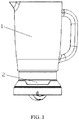
- a blade holder assembly for blender includes a cup body 1, a cup base 2 and a blade holder component 3, the cup body 1 is arranged on the cup base 2 and the cup base 2 connects the cup body 1 and the blade holder component 3.
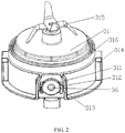
- the blade holder component 3 includes a blade holder 31 arranged just below the cup base and connected with the cup base; on the blade holder a blending blade 315 is arranged, and a waterproof ring 316 is arranged on the upper surface of the blade holder.
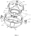
- a handle 32 is vertically arranged on the bottom of the blade holder, and on both sides of the handle 32, two protrusions 37 are respectively arranged. At both ends of the handle 32, a connecting member 33 is arranged.
- a locator 34 is arranged on the bottom of the blade holder to locate the relative position of the handle and the blade holder, and a connector 35 is arranged at the center of the blade holder.
- the blade holder, the locator and the connector are coaxially arranged, and the connector is arranged centrally in the blade holder.
- a guide bone 311 is arranged on the edge of the blade holder and in the guide bone a rotary fastener 312 is arranged on which two opposing fastening member 313 are arranged which are arranged on the edge of the rotary fastener.
- the connecting members at both ends of the handle are connected with the rotary fastener.
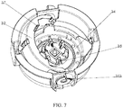
- a guide slot 21 is arranged on the inner edge of the cup base to connect with the guide bone, and in the guide slot, a polygonal convex button 22 is arranged that engages with the rotary fastener.
- the inner edge of the fastening member 313 form-fits with the outer edge of the convex button 22.
- the blade holder component further includes a screw 36 which fixes the rotary fastener on the blade holder.
- a locating slot 314 is arranged on the edge of the blade holder, and on said locator 34, two step-shaped locating bones 341 and two locating poles 342 are arranged which form a one-piece structure with the locator, and the locating bones are engaged inside the locating slot, and the locating poles and the connecting members at the both ends of the handle are engaged inside the locating bone.
- Four "H"-shaped fastening positions 344 for fixing are arranged on the bottom of the blade holder, and engaging positions 343 are arranged on the locator to engage with the fastening positions 344. When the fastening positions 344 and the engaging positions 343 are interlocked, the entire locator is locked on the bottom of the blade holder tightly.
- an engaging slot 23 is arranged which is connected with the locating slot 314.
- the present invention is implemented as follows: when holding the handle and when the plane in which the handle lies is perpendicular to the plane in which the blade holder lies, the blade holder is mounted into the cup base after the guide bone on the blade holder, which is equipped with rotary fastener, is aligned with the guide slot on the cup base. At this point of time, the guide bone, the locating slot on the blade holder are respectively inserted into the guide slot and the engaging slot on the cup base, and the fastening member on the rotary fastener is engaged on the vertical edge of the polygonal convex button. As shown in FIG.3 , at this point of time, the rotary fastener is in an unlocked position and the blade holder is separated from the cup base.
- the handle is pushed in bottom left direction or bottom right direction so that the handle is embedded completely into the edge of the blade holder and lies in the same plane with the blade holder.
- the rotation of the handle also brings the rotary fastener into rotation, and the fastening member on the rotary fastener rotates along the edge of the convex button and reaches the horizontal edge of the polygonal convex button.
- the rotary fastener lies in a locked position and the blade holder is interlocked with the cup base.
- the handle is separated so that it returns to a vertical state, the blade holder can be separated from the cup base.
- the present invention relates to a blade holder assembly for blender which has changed the connection type between handle and the blade holder on the blade holder component and between the blade holder and the cup base, and thus facilities the mounting and demounting of the whole blade holder assembly and is easy to operate, has a high security and easy to be widely employed.
- the invention makes use of rotation of the handle to bring the rotary fastener into rotation, and then the inner edge of the fastening member on the rotary fastener rotates along the outer edge of the convex button on the cup base and reaches locking position or separation position, so that a locking and a separation of the cup body with the blade holder is realized, and the whole structure is simple, easy to operate, and convenient. It is easy to detach the blade holder for cleaning when cleaning the blender blades and it is easy and convenient to operate and clean.
- the arrangement of the locator makes it easy to assemble the blade holder, and it is easy to locate.
Landscapes
- Engineering & Computer Science (AREA)
- Mechanical Engineering (AREA)
- Food Science & Technology (AREA)
- Food-Manufacturing Devices (AREA)
- Dental Tools And Instruments Or Auxiliary Dental Instruments (AREA)
Claims (8)
- Schaufelhalteranordnung für Mischer, umfassend einen Becherkörper (1), eine Becherbasis (2) und ein Schaufelhalterbauteil (3), worin der Becherkörper (1) auf der Becherbasis (2) angeordnet ist und die Becherbasis (2) den Becherkörper (1) mit dem Schaufelhalterbauteil (3) verbindet, worin das Schaufelhalterbauteil (3) einen Schaufelhalter (31), der gerade unter der Becherbasis angeordnet und mit der Becherbasis verbunden ist, umfasst; ein Handgriff (32) vertikal am Schaufelhalterboden angeordnet ist;
dadurch gekennzeichnet, dass Verbindungsteile (33) an beiden Enden des Handgriffs angeordnet sind; ein Lokalisierer (34) am Schaufelhalterboden angeordnet ist, um die relative Stellung des Handgriffs und des Schaufelhalters festzulegen; ein Verbinder (35) in der Mitte des Lokalisierers angeordnet ist, und der Schaufelhalter, der Lokalisierer und der Verbinder koaxial sind; eine Führungsstruktur (311) an der Kante des Schaufelhalters angeordnet ist, und ein Drehknopf (322) in der Führungsstruktur angeordnet ist; am Drehbefestiger zwei entgegengesetzte Befestigungselemente (313) angeordnet sind; die Verbindungsteile an beiden Enden des Handgriffs mit dem Drehbefestiger verbunden sind; ein Führungsschlitz (21) an der Innenkante der Becherbasis angeordnet ist, um sich mit der Führungsstruktur zu verbinden; im Führungsschlitz ein konvexer Knopf (22) angeordnet ist, um den Drehbefestiger zu befestigen. - Schaufelhalteranordnung nach Anspruch 1, worin ein Lokalisierungsschlitz (314) an der Kante des Schaufelhalters angeordnet ist und an dem Lokalisierer eine Lokalisierungsstruktur (341) und ein Lokalisierungsstab (342) angeordnet sind, welche eine einstückige Struktur mit dem Lokalisierer (341) bilden; die Lokalisierungsstruktur innerhalb des Lokalisierungsschlitzes eingerastet ist und der Lokalisierungsstab und die Verbindungsteile an den beiden Enden des Handgriffs innerhalb der Lokalisierungsstruktur angeordnet sind.
- Schaufelhalteranordnung nach Anspruch 2, worin vier H-förmige Befestigungspositionen (344) zur Befestigung am Schaufelhalterboden angeordnet sind, und am Lokalisierer (34) vier Eingriffspositionen (343) angeordnet sind, um mit den Befestigungspositionen einzugreifen.
- Schaufelhalteranordnung nach Anspruch 3, worin ein Eingriffsschlitz (23) in der Becherbasis angeordnet ist, um sich mit dem Lokalisierungsschlitz (314) zu verbinden.
- Schaufelhalteranordnung nach Anspruch 4, worin der konvexe Knopf (22) polygonal ist, das Befestigungselement an der Kante des Drehbefestigers angeordnet ist und die Innenkante des Befestigungselementes (313) mit der Außenkante des konvexen Knopfes (22) formschlüssig ist.
- Schaufelhalteranordnung nach den Ansprüchen 1-5, worin das Schaufelhalterbauteil ferner eine Schraube (36) umfasst, die den Drehbefestiger am Schaufelhalter fixiert.
- Schaufelhalteranordnung nach Anspruch 6, worin an zwei Seiten des Handgriffs (32) jeweils zwei Vorsprünge (37) angeordnet sind.
- Schaufelhalteranordnung nach Anspruch 7, worin am Schaufelhalter (31) eine Mischschaufel (315) angeordnet ist und an der Kante der Schaufelhalterfläche ein wasserfester Ring (316) angeordnet ist.
Applications Claiming Priority (1)
| Application Number | Priority Date | Filing Date | Title |
|---|---|---|---|
| CN201510154908.2A CN104771092B (zh) | 2015-04-03 | 2015-04-03 | 一种搅拌机的装配刀座 |
Publications (2)
| Publication Number | Publication Date |
|---|---|
| EP3075296A1 EP3075296A1 (de) | 2016-10-05 |
| EP3075296B1 true EP3075296B1 (de) | 2018-12-19 |
Family
ID=53613105
Family Applications (1)
| Application Number | Title | Priority Date | Filing Date |
|---|---|---|---|
| EP15180821.9A Active EP3075296B1 (de) | 2015-04-03 | 2015-08-12 | Schaufelhalteranordnung für mischer |
Country Status (3)
| Country | Link |
|---|---|
| US (1) | US9955820B2 (de) |
| EP (1) | EP3075296B1 (de) |
| CN (1) | CN104771092B (de) |
Families Citing this family (17)
| Publication number | Priority date | Publication date | Assignee | Title |
|---|---|---|---|---|
| AU2015291775B2 (en) * | 2014-07-17 | 2019-10-31 | Breville Pty Limited | Personal blender |
| US10898028B2 (en) * | 2017-06-30 | 2021-01-26 | Capbran Holdings, Llc | Mixer with safety mechanisms |
| CN107854007B (zh) * | 2017-11-28 | 2024-04-02 | 佛山市顺德区毅鸣佳塑料有限公司 | 食物料理机杯体与安装座连接结构 |
| CN109091033A (zh) | 2018-05-30 | 2018-12-28 | 浙江绍兴苏泊尔生活电器有限公司 | 料理机用搅拌杯组件及包括该搅拌杯组件的料理机 |
| CN109199148B (zh) * | 2018-06-15 | 2021-05-28 | 浙江绍兴苏泊尔生活电器有限公司 | 料理机用搅拌杯组件及包括该搅拌杯组件的料理机 |
| CN110151015A (zh) * | 2019-01-24 | 2019-08-23 | 浙江绍兴苏泊尔生活电器有限公司 | 料理机 |
| US11779159B2 (en) * | 2019-07-11 | 2023-10-10 | Sunbeam Products, Inc. | Locking blade base |
| CN112237388B (zh) * | 2019-07-19 | 2024-10-01 | 广东美的生活电器制造有限公司 | 食品料理机及其刀组安装结构和搅拌杯 |
| CN110279325A (zh) * | 2019-07-24 | 2019-09-27 | 佛山市威王日用电器有限公司 | 一种破壁料理机的杯体结构 |
| CN112294149B (zh) * | 2019-08-02 | 2024-07-23 | 广东美的生活电器制造有限公司 | 食物处理装置 |
| WO2021023087A1 (zh) * | 2019-08-02 | 2021-02-11 | 主力智业(深圳)电器实业有限公司 | 底盘组件和食物处理装置 |
| CN110720849A (zh) * | 2019-11-14 | 2020-01-24 | 惠阳亚伦塑胶电器实业有限公司 | 一种旋转式食物处理机 |
| CN114760893B (zh) * | 2019-11-21 | 2024-10-11 | 伊夫古德Fz有限责任公司 | 用于从冷冻食物配料制备鲜汁的机器 |
| CN113491456B (zh) * | 2021-07-16 | 2023-03-31 | 深圳市联创三金电器有限公司 | 固定器组件、刀座组件、容器组件以及食物料理机 |
| CN114532873B (zh) * | 2021-10-28 | 2023-10-27 | 浙江绍兴苏泊尔生活电器有限公司 | 搅拌杯与料理机 |
| CN115054137B (zh) * | 2022-02-24 | 2024-07-23 | 浙江绍兴苏泊尔生活电器有限公司 | 搅拌杯组件及料理机 |
| CN219331440U (zh) * | 2023-03-14 | 2023-07-14 | 江门市西屋厨房小家电有限公司 | 一种料理杯的装刀装置 |
Family Cites Families (34)
| Publication number | Priority date | Publication date | Assignee | Title |
|---|---|---|---|---|
| US2304476A (en) * | 1940-06-24 | 1942-12-08 | Stephen J Poplawski | Food and beverage mixer |
| GB953292A (en) * | 1962-11-06 | 1964-03-25 | Henry Adolph Dewenter | Shaft coupling |
| US3786999A (en) * | 1972-01-11 | 1974-01-22 | Ronson Corp | Safety mechanism to prevent shaft coupling when blades are exposed in a blender |
| JP3341961B2 (ja) * | 1994-02-28 | 2002-11-05 | 株式会社ユニシアジェックス | 軸継手構造 |
| BR9803559A (pt) * | 1998-09-09 | 2000-05-09 | Arno Sa | Liquidificador com lâminas removìveis |
| DE19912750A1 (de) * | 1999-03-22 | 2000-09-28 | Braun Gmbh | Sicherheitseinrichtung für einen Bechermixer |
| ATE255841T1 (de) * | 2000-06-22 | 2003-12-15 | Arno Sa | Küchenmaschine mit vorrichtung zum aufbewahren von werkzeugen |
| US8529118B2 (en) * | 2001-04-13 | 2013-09-10 | Sunbeam Products, Inc. | Blender cup with lid storage |
| US6609821B2 (en) * | 2001-04-13 | 2003-08-26 | Sunbeam Products, Inc. | Blender base with food processor capabilities |
| CN2618521Y (zh) * | 2003-05-26 | 2004-06-02 | 王瑞昌 | 榨汁机 |
| US7387269B2 (en) * | 2005-03-18 | 2008-06-17 | Whirlpool Corporation | Drive coupler for a food preparation device |
| GB2426384B (en) * | 2005-05-17 | 2008-02-13 | Kenwood Marks Ltd | Interlock system |
| US7566186B2 (en) * | 2005-05-20 | 2009-07-28 | Vita-Mix Corporation | Drive coupler for a blender |
| US20070140048A1 (en) * | 2005-12-16 | 2007-06-21 | Mahmoud Ismail | Seal and drain for blenders |
| US7950842B2 (en) * | 2007-03-05 | 2011-05-31 | Hamilton Beach Brands, Inc. | Durability monitoring and improvement of a blender |
| FR2917591B1 (fr) * | 2007-06-22 | 2009-07-31 | Seb Sa | Appareil de preparation culinaire muni d'un dispositif de securite |
| CN101754708B (zh) * | 2007-06-27 | 2012-04-25 | 伊恩·杰弗里·威尔逊 | 食物搅拌器组件和方法 |
| FR2923698A1 (fr) * | 2007-11-19 | 2009-05-22 | Seb Sa | Appareil electromenager de preparation culinaire comportant un support pour un organe de melange. |
| US7600706B2 (en) * | 2008-01-24 | 2009-10-13 | Yuming Huang | Safety food grinder |
| US8087818B2 (en) * | 2008-12-03 | 2012-01-03 | Whirlpool Corporation | Blade-motor coupler for a blender |
| CN201349994Y (zh) * | 2009-01-07 | 2009-11-25 | 九阳股份有限公司 | 料理机刀座与杯体的连接结构 |
| AU2011340785B2 (en) * | 2010-12-07 | 2017-03-02 | Breville Pty Limited | Blender jug and coupling |
| CN103957759B (zh) * | 2011-10-05 | 2016-10-26 | 布瑞威利私人有限公司 | 叶片和轴承组件 |
| US9924836B2 (en) * | 2012-02-15 | 2018-03-27 | Aktiebolaget Electrolux | Mixer household appliance |
| CN202820897U (zh) * | 2012-10-31 | 2013-03-27 | 惠阳亚伦塑胶电器实业有限公司 | 一种煮食搅拌机 |
| CN203723982U (zh) * | 2013-01-28 | 2014-07-23 | 九阳股份有限公司 | 一种易操作料理机 |
| US9700177B2 (en) * | 2013-03-01 | 2017-07-11 | Whirlpool Corporation | Food processing device jar lock |
| TW201502392A (zh) * | 2013-03-15 | 2015-01-16 | Vita Mix Corp | 驅動耦合器用固定夾插入件 |
| KR101497218B1 (ko) * | 2013-07-01 | 2015-02-27 | 청주대학교 산학협력단 | 수동 블렌더 |
| CN203524522U (zh) * | 2013-09-30 | 2014-04-09 | 江门市新会区浩信电器制造有限公司 | 一种具有双钩式揉面钩的多功能揉面机 |
| EP3111810A4 (de) * | 2014-02-26 | 2017-12-13 | LEE, Ming-hsien | Schneidwellenanordnung eines entsafter-schneidwerkzeughalters |
| CN103976667B (zh) * | 2014-05-13 | 2016-08-24 | 林锦坚 | 一种方便清洗的组合式搅拌杯 |
| CN204520407U (zh) * | 2015-04-03 | 2015-08-05 | 惠阳亚伦塑胶电器实业有限公司 | 一种搅拌机的装配刀座 |
| US10327595B2 (en) * | 2016-03-23 | 2019-06-25 | Capbran Holdings, Llc | Food processor |
-
2015
- 2015-04-03 CN CN201510154908.2A patent/CN104771092B/zh active Active
- 2015-08-12 EP EP15180821.9A patent/EP3075296B1/de active Active
- 2015-08-19 US US14/829,643 patent/US9955820B2/en active Active
Non-Patent Citations (1)
| Title |
|---|
| None * |
Also Published As
| Publication number | Publication date |
|---|---|
| CN104771092B (zh) | 2017-08-25 |
| US20160287017A1 (en) | 2016-10-06 |
| CN104771092A (zh) | 2015-07-15 |
| EP3075296A1 (de) | 2016-10-05 |
| US9955820B2 (en) | 2018-05-01 |
Similar Documents
| Publication | Publication Date | Title |
|---|---|---|
| US9955820B2 (en) | Blade holder assembly for blender | |
| ES2337294T5 (es) | Aparato de cocina de motor eléctrico con bloqueo eléctrico o electrónico | |
| US8240909B2 (en) | Blender jar interlock | |
| CN104582550B (zh) | 用于家用食物处理设备的安全系统 | |
| US9527052B2 (en) | Blender jar collars and interlocks | |
| EA039029B1 (ru) | Миксер с предохранительными механизмами | |
| US10799070B2 (en) | Mixing tool lock for a kitchen appliance | |
| US20150208844A1 (en) | Food processor | |
| CN109091034B (zh) | 料理机用搅拌杯组件及包括该搅拌杯组件的料理机 | |
| US11877696B2 (en) | Food processor | |
| ES2820549T3 (es) | Dispositivo de preparación de alimentos con mecanismo de bloqueo | |
| WO2016077424A1 (en) | Appliance with integrated agitator assembly | |
| EP1045658A1 (de) | Zusatzgerät mit sicherheitsglied für küchenmaschinen | |
| WO2017139942A1 (zh) | 一种工业连接器和连接结构 | |
| KR20200003202A (ko) | 블레이드들을 보울 상에 잠금 고정하기 위한 장치를 구비한, 블렌더 유형의, 액상 또는 반죽질의 식품 조리용 믹싱 및 블렌딩 기기 | |
| CN117562402A (zh) | 一种壶盖结构 | |
| KR101499112B1 (ko) | 조리용기의 탈착식 뚜껑 손잡이 | |
| CN102573587A (zh) | 旋转烹调装置 | |
| CN204520407U (zh) | 一种搅拌机的装配刀座 | |
| ES2879360T3 (es) | Aparato de mezcla y de combinación para unas preparaciones alimentarias líquidas o pastosas, equipado con un sistema de engatillado de un portacuchillas sobre un anillo de enclavamiento | |
| CN110384422A (zh) | 一种拆卸时防刀组跌落结构和搅拌装置 | |
| CN115209772B (zh) | 刀具保持器、壶组合和搅拌器 | |
| RU2620952C2 (ru) | Электробытовой прибор для резки пищевых продуктов с размещением принадлежностей для резки продуктов | |
| CN205433283U (zh) | 烹饪器具 | |
| CN217959734U (zh) | 烹饪器具 |
Legal Events
| Date | Code | Title | Description |
|---|---|---|---|
| PUAI | Public reference made under article 153(3) epc to a published international application that has entered the european phase |
Free format text: ORIGINAL CODE: 0009012 |
|
| 17P | Request for examination filed |
Effective date: 20150812 |
|
| AK | Designated contracting states |
Kind code of ref document: A1 Designated state(s): AL AT BE BG CH CY CZ DE DK EE ES FI FR GB GR HR HU IE IS IT LI LT LU LV MC MK MT NL NO PL PT RO RS SE SI SK SM TR |
|
| AX | Request for extension of the european patent |
Extension state: BA ME |
|
| STAA | Information on the status of an ep patent application or granted ep patent |
Free format text: STATUS: REQUEST FOR EXAMINATION WAS MADE |
|
| GRAP | Despatch of communication of intention to grant a patent |
Free format text: ORIGINAL CODE: EPIDOSNIGR1 |
|
| STAA | Information on the status of an ep patent application or granted ep patent |
Free format text: STATUS: GRANT OF PATENT IS INTENDED |
|
| INTG | Intention to grant announced |
Effective date: 20180710 |
|
| GRAS | Grant fee paid |
Free format text: ORIGINAL CODE: EPIDOSNIGR3 |
|
| GRAA | (expected) grant |
Free format text: ORIGINAL CODE: 0009210 |
|
| STAA | Information on the status of an ep patent application or granted ep patent |
Free format text: STATUS: THE PATENT HAS BEEN GRANTED |
|
| AK | Designated contracting states |
Kind code of ref document: B1 Designated state(s): AL AT BE BG CH CY CZ DE DK EE ES FI FR GB GR HR HU IE IS IT LI LT LU LV MC MK MT NL NO PL PT RO RS SE SI SK SM TR |
|
| REG | Reference to a national code |
Ref country code: GB Ref legal event code: FG4D |
|
| REG | Reference to a national code |
Ref country code: CH Ref legal event code: EP |
|
| REG | Reference to a national code |
Ref country code: IE Ref legal event code: FG4D |
|
| REG | Reference to a national code |
Ref country code: AT Ref legal event code: REF Ref document number: 1077771 Country of ref document: AT Kind code of ref document: T Effective date: 20190115 |
|
| REG | Reference to a national code |
Ref country code: DE Ref legal event code: R096 Ref document number: 602015021778 Country of ref document: DE |
|
| REG | Reference to a national code |
Ref country code: NL Ref legal event code: MP Effective date: 20181219 |
|
| PG25 | Lapsed in a contracting state [announced via postgrant information from national office to epo] |
Ref country code: LV Free format text: LAPSE BECAUSE OF FAILURE TO SUBMIT A TRANSLATION OF THE DESCRIPTION OR TO PAY THE FEE WITHIN THE PRESCRIBED TIME-LIMIT Effective date: 20181219 Ref country code: NO Free format text: LAPSE BECAUSE OF FAILURE TO SUBMIT A TRANSLATION OF THE DESCRIPTION OR TO PAY THE FEE WITHIN THE PRESCRIBED TIME-LIMIT Effective date: 20190319 Ref country code: LT Free format text: LAPSE BECAUSE OF FAILURE TO SUBMIT A TRANSLATION OF THE DESCRIPTION OR TO PAY THE FEE WITHIN THE PRESCRIBED TIME-LIMIT Effective date: 20181219 Ref country code: HR Free format text: LAPSE BECAUSE OF FAILURE TO SUBMIT A TRANSLATION OF THE DESCRIPTION OR TO PAY THE FEE WITHIN THE PRESCRIBED TIME-LIMIT Effective date: 20181219 Ref country code: BG Free format text: LAPSE BECAUSE OF FAILURE TO SUBMIT A TRANSLATION OF THE DESCRIPTION OR TO PAY THE FEE WITHIN THE PRESCRIBED TIME-LIMIT Effective date: 20190319 Ref country code: FI Free format text: LAPSE BECAUSE OF FAILURE TO SUBMIT A TRANSLATION OF THE DESCRIPTION OR TO PAY THE FEE WITHIN THE PRESCRIBED TIME-LIMIT Effective date: 20181219 |
|
| REG | Reference to a national code |
Ref country code: LT Ref legal event code: MG4D |
|
| REG | Reference to a national code |
Ref country code: AT Ref legal event code: MK05 Ref document number: 1077771 Country of ref document: AT Kind code of ref document: T Effective date: 20181219 |
|
| PG25 | Lapsed in a contracting state [announced via postgrant information from national office to epo] |
Ref country code: SE Free format text: LAPSE BECAUSE OF FAILURE TO SUBMIT A TRANSLATION OF THE DESCRIPTION OR TO PAY THE FEE WITHIN THE PRESCRIBED TIME-LIMIT Effective date: 20181219 Ref country code: RS Free format text: LAPSE BECAUSE OF FAILURE TO SUBMIT A TRANSLATION OF THE DESCRIPTION OR TO PAY THE FEE WITHIN THE PRESCRIBED TIME-LIMIT Effective date: 20181219 Ref country code: AL Free format text: LAPSE BECAUSE OF FAILURE TO SUBMIT A TRANSLATION OF THE DESCRIPTION OR TO PAY THE FEE WITHIN THE PRESCRIBED TIME-LIMIT Effective date: 20181219 Ref country code: GR Free format text: LAPSE BECAUSE OF FAILURE TO SUBMIT A TRANSLATION OF THE DESCRIPTION OR TO PAY THE FEE WITHIN THE PRESCRIBED TIME-LIMIT Effective date: 20190320 |
|
| PG25 | Lapsed in a contracting state [announced via postgrant information from national office to epo] |
Ref country code: NL Free format text: LAPSE BECAUSE OF FAILURE TO SUBMIT A TRANSLATION OF THE DESCRIPTION OR TO PAY THE FEE WITHIN THE PRESCRIBED TIME-LIMIT Effective date: 20181219 |
|
| PG25 | Lapsed in a contracting state [announced via postgrant information from national office to epo] |
Ref country code: IT Free format text: LAPSE BECAUSE OF FAILURE TO SUBMIT A TRANSLATION OF THE DESCRIPTION OR TO PAY THE FEE WITHIN THE PRESCRIBED TIME-LIMIT Effective date: 20181219 Ref country code: CZ Free format text: LAPSE BECAUSE OF FAILURE TO SUBMIT A TRANSLATION OF THE DESCRIPTION OR TO PAY THE FEE WITHIN THE PRESCRIBED TIME-LIMIT Effective date: 20181219 Ref country code: PT Free format text: LAPSE BECAUSE OF FAILURE TO SUBMIT A TRANSLATION OF THE DESCRIPTION OR TO PAY THE FEE WITHIN THE PRESCRIBED TIME-LIMIT Effective date: 20190419 Ref country code: PL Free format text: LAPSE BECAUSE OF FAILURE TO SUBMIT A TRANSLATION OF THE DESCRIPTION OR TO PAY THE FEE WITHIN THE PRESCRIBED TIME-LIMIT Effective date: 20181219 Ref country code: ES Free format text: LAPSE BECAUSE OF FAILURE TO SUBMIT A TRANSLATION OF THE DESCRIPTION OR TO PAY THE FEE WITHIN THE PRESCRIBED TIME-LIMIT Effective date: 20181219 |
|
| PG25 | Lapsed in a contracting state [announced via postgrant information from national office to epo] |
Ref country code: IS Free format text: LAPSE BECAUSE OF FAILURE TO SUBMIT A TRANSLATION OF THE DESCRIPTION OR TO PAY THE FEE WITHIN THE PRESCRIBED TIME-LIMIT Effective date: 20190419 Ref country code: RO Free format text: LAPSE BECAUSE OF FAILURE TO SUBMIT A TRANSLATION OF THE DESCRIPTION OR TO PAY THE FEE WITHIN THE PRESCRIBED TIME-LIMIT Effective date: 20181219 Ref country code: SK Free format text: LAPSE BECAUSE OF FAILURE TO SUBMIT A TRANSLATION OF THE DESCRIPTION OR TO PAY THE FEE WITHIN THE PRESCRIBED TIME-LIMIT Effective date: 20181219 Ref country code: EE Free format text: LAPSE BECAUSE OF FAILURE TO SUBMIT A TRANSLATION OF THE DESCRIPTION OR TO PAY THE FEE WITHIN THE PRESCRIBED TIME-LIMIT Effective date: 20181219 Ref country code: SM Free format text: LAPSE BECAUSE OF FAILURE TO SUBMIT A TRANSLATION OF THE DESCRIPTION OR TO PAY THE FEE WITHIN THE PRESCRIBED TIME-LIMIT Effective date: 20181219 |
|
| REG | Reference to a national code |
Ref country code: DE Ref legal event code: R097 Ref document number: 602015021778 Country of ref document: DE |
|
| PLBE | No opposition filed within time limit |
Free format text: ORIGINAL CODE: 0009261 |
|
| STAA | Information on the status of an ep patent application or granted ep patent |
Free format text: STATUS: NO OPPOSITION FILED WITHIN TIME LIMIT |
|
| PG25 | Lapsed in a contracting state [announced via postgrant information from national office to epo] |
Ref country code: AT Free format text: LAPSE BECAUSE OF FAILURE TO SUBMIT A TRANSLATION OF THE DESCRIPTION OR TO PAY THE FEE WITHIN THE PRESCRIBED TIME-LIMIT Effective date: 20181219 Ref country code: DK Free format text: LAPSE BECAUSE OF FAILURE TO SUBMIT A TRANSLATION OF THE DESCRIPTION OR TO PAY THE FEE WITHIN THE PRESCRIBED TIME-LIMIT Effective date: 20181219 |
|
| 26N | No opposition filed |
Effective date: 20190920 |
|
| PG25 | Lapsed in a contracting state [announced via postgrant information from national office to epo] |
Ref country code: SI Free format text: LAPSE BECAUSE OF FAILURE TO SUBMIT A TRANSLATION OF THE DESCRIPTION OR TO PAY THE FEE WITHIN THE PRESCRIBED TIME-LIMIT Effective date: 20181219 |
|
| PG25 | Lapsed in a contracting state [announced via postgrant information from national office to epo] |
Ref country code: TR Free format text: LAPSE BECAUSE OF FAILURE TO SUBMIT A TRANSLATION OF THE DESCRIPTION OR TO PAY THE FEE WITHIN THE PRESCRIBED TIME-LIMIT Effective date: 20181219 |
|
| PG25 | Lapsed in a contracting state [announced via postgrant information from national office to epo] |
Ref country code: CH Free format text: LAPSE BECAUSE OF NON-PAYMENT OF DUE FEES Effective date: 20190831 Ref country code: LI Free format text: LAPSE BECAUSE OF NON-PAYMENT OF DUE FEES Effective date: 20190831 Ref country code: MC Free format text: LAPSE BECAUSE OF FAILURE TO SUBMIT A TRANSLATION OF THE DESCRIPTION OR TO PAY THE FEE WITHIN THE PRESCRIBED TIME-LIMIT Effective date: 20181219 Ref country code: LU Free format text: LAPSE BECAUSE OF NON-PAYMENT OF DUE FEES Effective date: 20190812 |
|
| REG | Reference to a national code |
Ref country code: BE Ref legal event code: MM Effective date: 20190831 |
|
| PG25 | Lapsed in a contracting state [announced via postgrant information from national office to epo] |
Ref country code: IE Free format text: LAPSE BECAUSE OF NON-PAYMENT OF DUE FEES Effective date: 20190812 |
|
| PG25 | Lapsed in a contracting state [announced via postgrant information from national office to epo] |
Ref country code: BE Free format text: LAPSE BECAUSE OF NON-PAYMENT OF DUE FEES Effective date: 20190831 |
|
| PG25 | Lapsed in a contracting state [announced via postgrant information from national office to epo] |
Ref country code: CY Free format text: LAPSE BECAUSE OF FAILURE TO SUBMIT A TRANSLATION OF THE DESCRIPTION OR TO PAY THE FEE WITHIN THE PRESCRIBED TIME-LIMIT Effective date: 20181219 |
|
| VS25 | Lapsed in a validation state [announced via postgrant information from nat. office to epo] |
Ref country code: MA Free format text: LAPSE BECAUSE OF FAILURE TO SUBMIT A TRANSLATION OF THE DESCRIPTION OR TO PAY THE FEE WITHIN THE PRESCRIBED TIME-LIMIT Effective date: 20181219 |
|
| PG25 | Lapsed in a contracting state [announced via postgrant information from national office to epo] |
Ref country code: MT Free format text: LAPSE BECAUSE OF FAILURE TO SUBMIT A TRANSLATION OF THE DESCRIPTION OR TO PAY THE FEE WITHIN THE PRESCRIBED TIME-LIMIT Effective date: 20181219 Ref country code: HU Free format text: LAPSE BECAUSE OF FAILURE TO SUBMIT A TRANSLATION OF THE DESCRIPTION OR TO PAY THE FEE WITHIN THE PRESCRIBED TIME-LIMIT; INVALID AB INITIO Effective date: 20150812 |
|
| PG25 | Lapsed in a contracting state [announced via postgrant information from national office to epo] |
Ref country code: MK Free format text: LAPSE BECAUSE OF FAILURE TO SUBMIT A TRANSLATION OF THE DESCRIPTION OR TO PAY THE FEE WITHIN THE PRESCRIBED TIME-LIMIT Effective date: 20181219 |
|
| PGFP | Annual fee paid to national office [announced via postgrant information from national office to epo] |
Ref country code: GB Payment date: 20220704 Year of fee payment: 8 |
|
| PGFP | Annual fee paid to national office [announced via postgrant information from national office to epo] |
Ref country code: FR Payment date: 20220823 Year of fee payment: 8 |
|
| GBPC | Gb: european patent ceased through non-payment of renewal fee |
Effective date: 20230812 |
|
| PG25 | Lapsed in a contracting state [announced via postgrant information from national office to epo] |
Ref country code: GB Free format text: LAPSE BECAUSE OF NON-PAYMENT OF DUE FEES Effective date: 20230812 |
|
| PG25 | Lapsed in a contracting state [announced via postgrant information from national office to epo] |
Ref country code: GB Free format text: LAPSE BECAUSE OF NON-PAYMENT OF DUE FEES Effective date: 20230812 Ref country code: FR Free format text: LAPSE BECAUSE OF NON-PAYMENT OF DUE FEES Effective date: 20230831 |
|
| PGFP | Annual fee paid to national office [announced via postgrant information from national office to epo] |
Ref country code: DE Payment date: 20250717 Year of fee payment: 11 |