EP3075231A1 - Plant growth control system and method - Google Patents
Plant growth control system and method Download PDFInfo
- Publication number
- EP3075231A1 EP3075231A1 EP16158688.8A EP16158688A EP3075231A1 EP 3075231 A1 EP3075231 A1 EP 3075231A1 EP 16158688 A EP16158688 A EP 16158688A EP 3075231 A1 EP3075231 A1 EP 3075231A1
- Authority
- EP
- European Patent Office
- Prior art keywords
- plant
- light source
- controllable light
- irradiation position
- information
- Prior art date
- Legal status (The legal status is an assumption and is not a legal conclusion. Google has not performed a legal analysis and makes no representation as to the accuracy of the status listed.)
- Granted
Links
Images


Classifications
-
- A—HUMAN NECESSITIES
- A01—AGRICULTURE; FORESTRY; ANIMAL HUSBANDRY; HUNTING; TRAPPING; FISHING
- A01G—HORTICULTURE; CULTIVATION OF VEGETABLES, FLOWERS, RICE, FRUIT, VINES, HOPS OR SEAWEED; FORESTRY; WATERING
- A01G7/00—Botany in general
- A01G7/04—Electric or magnetic or acoustic treatment of plants for promoting growth
- A01G7/045—Electric or magnetic or acoustic treatment of plants for promoting growth with electric lighting
-
- G—PHYSICS
- G05—CONTROLLING; REGULATING
- G05B—CONTROL OR REGULATING SYSTEMS IN GENERAL; FUNCTIONAL ELEMENTS OF SUCH SYSTEMS; MONITORING OR TESTING ARRANGEMENTS FOR SUCH SYSTEMS OR ELEMENTS
- G05B19/00—Program-control systems
- G05B19/02—Program-control systems electric
- G05B19/04—Program control other than numerical control, i.e. in sequence controllers or logic controllers
- G05B19/042—Program control other than numerical control, i.e. in sequence controllers or logic controllers using digital processors
- G05B19/0421—Multiprocessor system
-
- A—HUMAN NECESSITIES
- A01—AGRICULTURE; FORESTRY; ANIMAL HUSBANDRY; HUNTING; TRAPPING; FISHING
- A01G—HORTICULTURE; CULTIVATION OF VEGETABLES, FLOWERS, RICE, FRUIT, VINES, HOPS OR SEAWEED; FORESTRY; WATERING
- A01G9/00—Cultivation in receptacles, forcing-frames or greenhouses; Edging for beds, lawn or the like
- A01G9/20—Forcing-frames; Lights, i.e. glass panels covering the forcing-frames
-
- F—MECHANICAL ENGINEERING; LIGHTING; HEATING; WEAPONS; BLASTING
- F21—LIGHTING
- F21V—FUNCTIONAL FEATURES OR DETAILS OF LIGHTING DEVICES OR SYSTEMS THEREOF; STRUCTURAL COMBINATIONS OF LIGHTING DEVICES WITH OTHER ARTICLES, NOT OTHERWISE PROVIDED FOR
- F21V23/00—Arrangement of electric circuit elements in or on lighting devices
- F21V23/003—Arrangement of electric circuit elements in or on lighting devices the elements being electronics drivers or controllers for operating the light source, e.g. for a LED array
-
- F—MECHANICAL ENGINEERING; LIGHTING; HEATING; WEAPONS; BLASTING
- F21—LIGHTING
- F21V—FUNCTIONAL FEATURES OR DETAILS OF LIGHTING DEVICES OR SYSTEMS THEREOF; STRUCTURAL COMBINATIONS OF LIGHTING DEVICES WITH OTHER ARTICLES, NOT OTHERWISE PROVIDED FOR
- F21V23/00—Arrangement of electric circuit elements in or on lighting devices
- F21V23/04—Arrangement of electric circuit elements in or on lighting devices the elements being switches
- F21V23/0442—Arrangement of electric circuit elements in or on lighting devices the elements being switches activated by means of a sensor, e.g. motion or photodetectors
- F21V23/0471—Arrangement of electric circuit elements in or on lighting devices the elements being switches activated by means of a sensor, e.g. motion or photodetectors the sensor detecting the proximity, the presence or the movement of an object or a person
-
- G—PHYSICS
- G05—CONTROLLING; REGULATING
- G05B—CONTROL OR REGULATING SYSTEMS IN GENERAL; FUNCTIONAL ELEMENTS OF SUCH SYSTEMS; MONITORING OR TESTING ARRANGEMENTS FOR SUCH SYSTEMS OR ELEMENTS
- G05B15/00—Systems controlled by a computer
- G05B15/02—Systems controlled by a computer electric
-
- F—MECHANICAL ENGINEERING; LIGHTING; HEATING; WEAPONS; BLASTING
- F21—LIGHTING
- F21V—FUNCTIONAL FEATURES OR DETAILS OF LIGHTING DEVICES OR SYSTEMS THEREOF; STRUCTURAL COMBINATIONS OF LIGHTING DEVICES WITH OTHER ARTICLES, NOT OTHERWISE PROVIDED FOR
- F21V14/00—Controlling the distribution of the light emitted by adjustment of elements
- F21V14/02—Controlling the distribution of the light emitted by adjustment of elements by movement of light sources
-
- G—PHYSICS
- G05—CONTROLLING; REGULATING
- G05B—CONTROL OR REGULATING SYSTEMS IN GENERAL; FUNCTIONAL ELEMENTS OF SUCH SYSTEMS; MONITORING OR TESTING ARRANGEMENTS FOR SUCH SYSTEMS OR ELEMENTS
- G05B13/00—Adaptive control systems, i.e. systems automatically adjusting themselves to have a performance which is optimum according to some preassigned criterion
- G05B13/02—Adaptive control systems, i.e. systems automatically adjusting themselves to have a performance which is optimum according to some preassigned criterion electric
-
- G—PHYSICS
- G05—CONTROLLING; REGULATING
- G05B—CONTROL OR REGULATING SYSTEMS IN GENERAL; FUNCTIONAL ELEMENTS OF SUCH SYSTEMS; MONITORING OR TESTING ARRANGEMENTS FOR SUCH SYSTEMS OR ELEMENTS
- G05B19/00—Program-control systems
- G05B19/02—Program-control systems electric
- G05B19/04—Program control other than numerical control, i.e. in sequence controllers or logic controllers
-
- Y—GENERAL TAGGING OF NEW TECHNOLOGICAL DEVELOPMENTS; GENERAL TAGGING OF CROSS-SECTIONAL TECHNOLOGIES SPANNING OVER SEVERAL SECTIONS OF THE IPC; TECHNICAL SUBJECTS COVERED BY FORMER USPC CROSS-REFERENCE ART COLLECTIONS [XRACs] AND DIGESTS
- Y02—TECHNOLOGIES OR APPLICATIONS FOR MITIGATION OR ADAPTATION AGAINST CLIMATE CHANGE
- Y02P—CLIMATE CHANGE MITIGATION TECHNOLOGIES IN THE PRODUCTION OR PROCESSING OF GOODS
- Y02P60/00—Technologies relating to agriculture, livestock or agroalimentary industries
- Y02P60/14—Measures for saving energy, e.g. in green houses
Definitions
- the present invention relates to the field of plant cultivation, and more particularly, to a plant growth control system and method.
- the user In order to enable the plant to receive uniform light irradiation, and then to help the plant grow better, the user needs to rotate the flower pot where the plant grows by a certain direction at intervals of a predetermined time period. For example, the user rotates the flower pot by 180 degrees every week.
- the present invention provides a plant growth control system and method.
- the following technical solutions are employed.
- the invention relates to a plant growth control system.
- the system comprises: an information collector, a processor connected to the information collector, and a controllable light source; wherein the information collector is configured to acquire growth information of a plant, the growth information comprising at least one of branch and leaf distribution information of the plant and flower distribution information of the plant; and the processor is configured to determine, according to the growth information, a target irradiation position of the controllable light source in the plant, and to control the controllable light source to irradiate the target irradiation position in the plant.
- the information collector comprises at least two light intensity sensors; wherein the light intensity sensors are configured to acquire light intensities yielded after ambient light penetrates through the plant; and the processor is further configured to determine the growth information of the plant according to the light intensities acquired by the at least two light intensity sensors.
- the system further comprises a flower pot, wherein the at least two light intensity sensors are arranged on the edge of the flower pot.
- the information collector comprises a camera; wherein the camera is configured to acquire an image containing the plant; and the processor is further configured to acquire the growth information of the plant according to the image.
- controllable light source is in a moving state or a stationary state under control of the processor.
- the system further comprises a base for accommodating the flower pot, wherein the base is in a rotation state or a stationary state under control of the processor.
- the system further comprises a human body infrared sensor; wherein the human body infrared sensor is configured to detect a human body infrared signal in an environment; and the processor is further configured to, when the human body infrared sensor detects a human body infrared signal, control the controllable light source in a predetermined control manner and/or control the flower pot where the plant grows to rotate, the predetermined control manner comprising adjusting luminance of the controllable light source or controlling the controllable light source to blink.
- a human body infrared sensor is configured to detect a human body infrared signal in an environment
- the processor is further configured to, when the human body infrared sensor detects a human body infrared signal, control the controllable light source in a predetermined control manner and/or control the flower pot where the plant grows to rotate, the predetermined control manner comprising adjusting luminance of the controllable light source or controlling the controllable light source to blink.
- the invention relates to a plant growth control method.
- the method comprises:
- the step of acquiring growth information of a plant comprises:
- the step of controlling the controllable light source to irradiate the target irradiation position in the plant comprises:
- the step of acquiring growth information of a plant comprises:
- the image further contains the light source
- the step of controlling the controllable light source to irradiate the target irradiation position in the plant comprises:
- the step of determining, according to the growth information, a target irradiation position of the controllable light source in the plant comprises:
- the method further comprises:
- the steps of the plant growth control method are determined by computer program instructions.
- the invention is also directed to a computer program for executing the steps of a plant growth control method as described above when this program is executed by a computer.
- This program can use any programming language and take the form of source code, object code or a code intermediate between source code and object code, such as a partially compiled form, or any other desirable form.
- the invention is also directed to a computer-readable information medium containing instructions of a computer program as described above.
- the information medium can be any entity or device capable of storing the program.
- the support can include storage means such as a ROM, for example a CD ROM or a microelectronic circuit ROM, or magnetic storage means, for example a diskette (floppy disk) or a hard disk.
- the information medium can be an integrated circuit in which the program is incorporated, the circuit being adapted to execute the method in question or to be used in its execution.
- Growth information of a plant is acquired, a target irradiation position of a controllable light source in the plant is determined according to the growth information, and thus the controllable light source is controlled to irradiate the target irradiation position in the plant.
- Fig. 1 is a schematic structural diagram illustrating a plant growth control system according to an example embodiment of the present invention.
- the plant growth control system 100 may comprise: an information collector 110, a processor 120 connected to the information collector 110, and at least one controllable light source 130.
- the information collector 110 is configured to acquire growth information of a plant, the growth information comprising at least one of branch and leaf distribution information of the plant and flower distribution information of the plant.
- the processor 120 is configured to determine, according to the growth information, a target irradiation position of the controllable light source 130 in the plant, and to control the controllable light source 130 to irradiate the target irradiation position in the plant.
- the controllable light source 130 refers to a light source which may change its irradiation position in the plant.
- the controllable light source is rotatable in terms of irradiation direction or movable in terms of position, or the plant is rotatable relative to the position of the controllable light source.
- the processor 120 may be connected to the controllable light source 130.
- the controllable light source 130 may be a lamp, and the lamp changes its irradiation direction under control of the processor 120.
- the controllable light source 130 may also be a light source comprising a mechanical part and a lamp.
- the mechanical part may change its position under control of the processor 120, and thus drives the lamp to change its position.
- the mechanical part may be a mechanical arm, a circular guide rail, a magnetic suspension chassis or the like, which is not limited in this embodiment.
- Fig. 1 illustrates the system by using an example in which the controllable light source 130 is a lamp.
- the plant growth control system provided by the embodiment of the present invention, growth information of a plant is acquired, a target irradiation position of a controllable light source in the plant is determined according to the growth information, and thus the controllable light source is controlled to irradiate the target irradiation position in the plant.
- the plant growth control system may collect relevant information by using a light intensity sensor or a camera and thus acquire growth information of a plant.
- the information collector 110 may comprise light intensity sensors or a camera. Therefore, plant growth control systems under such two circumstances where the information collector comprises light intensity sensors and where the information collector comprises a camera are described in different embodiments.
- Fig. 2A is a schematic structural diagram illustrating a plant growth control system according to another example embodiment of the present invention. The system is described in this embodiment using an information collector equipped with at least two light intensity sensors as an example. As illustrated in Fig. 2A , the plant growth control system 200 may comprise: an information collector 210, a processor 220 connected to the information collector 210, and at least one controllable light source 230.
- the information collector 210 is configured to acquire growth information of a plant, the growth information comprising at least one of branch and leaf distribution information of the plant and flower distribution information of the plant.
- the processor 220 is configured to determine, according to the growth information, a target irradiation position of the controllable light source 230 in the plant, and to control the controllable light source 230 to irradiate the target irradiation position in the plant.
- the controllable light source 230 refers to a light source which may change its irradiation position in the plant.
- the controllable light source is rotatable in terms of irradiation direction or movable in terms of position, or the plant is rotatable relative to the position of the controllable light source.
- the processor 220 may be connected to the controllable light source 230.
- controllable light source 230 may be a lamp, and the lamp changes its irradiation direction under control of the processor 220.
- controllable light source 230 may also be a light source comprising a mechanical part and a lamp.
- the mechanical part may change its position under control of the processor 220, and thus drives the lamp to change its position.
- the mechanical part may be a mechanical arm, a circular guide rail, a magnetic suspension chassis or the like, which is not limited in this embodiment.
- the processor 220 may determine the target irradiation position according to the following manners.
- the processor 220 may determine a side of the plant where a sparse degree of the branch and leaf distribution is less than a first threshold as the target irradiation position (the growth on the side of the plant is promoted by giving more light irradiation to the side).
- the processor 220 may determine a side of the plant where a sparse degree of the branch and leaf distribution is greater than a second threshold as the target irradiation position.
- the processor 220 may determine a position of the plant where the flowers are blooming as the target irradiation position.
- the processor 220 may determine a position of the plant where the flowers are still ready to bloom as the target irradiation position. This embodiment is described only by using the scenario where the processor determines the target irradiation position according to the above manner as an example. Optionally, the processor 220 may also determine the target irradiation position according to another manner, which is not limited in this embodiment.
- the information collector 210 may comprise at least two light intensity sensors, and each of the light intensity sensors may be configured to acquire a light intensity yielded after ambient light penetrates through the plant.
- the at least two light intensity sensors are generally arranged at the bottom of the plant. As such, when the ambient light penetrates through the plant and reaches the light intensity sensors arranged at the bottom of the plant, the light intensity sensors may respectively acquire the light intensities. To acquire distributions of the plant in various directions, the at least two light intensity sensors may be evenly arranged around the roots of the plant. In addition, each of the light intensity sensors may be always in a working state. Nevertheless, to prolong the service life of the light intensity sensors, the plant growth control system may further comprise switches for controlling the light intensity sensors. When the growth of the plant needs to be controlled, the switches are turned on and the light intensity sensors are set to the working state.
- the processor 220 may correspondingly determine the growth information of the plant according to the light intensities acquired by the at least two light intensity sensors.
- the sparser the growth of the plant is, the greater the light intensity yielded after the ambient light penetrates through the plant is; and the denser the growth of the plant is, the less the light intensity yielded after the ambient light penetrates through the plant is. Therefore, after the processor 220 obtains the light intensities, the processor 220 may determine the side corresponding to the light intensity sensor which collects a weak light intensity in the plant as a dense side, and determine the side corresponding to the light intensity sensor which collects a strong light intensity in the plant as a sparse side.
- the processor 220 may determine the branch and leaf distribution information of the plant.
- the plant growth control system may further comprise a flower pot, and at least two light intensity sensors may be arranged on the edge of the flower pot.
- the at least two light intensity sensors may be evenly arranged on the edge of the flower pot.
- the flower pot is divided into four regions in the unit of 90 degrees, and the four light intensity sensors may be arranged in the flower pot at four positions A, B, C and D as illustrated in Fig. 2B .
- each of the light intensity sensors may be integrated sensors of the flower pot; or the flower pot and the light intensity sensors may be two independent parts, and before use, a user may install the light intensity sensors on the edge of the flower pot, which is not limited in this embodiment.
- the controllable light source 230 in the plant growth control system may be in a moving state or a stationary state under control of the processor 220.
- the processor 220 may control the controllable light source 230 to move, and thus cause the irradiation position of the controllable light source 230 to move to the target irradiation position in the plant.
- the movement may be movement made by the controllable light source 230 via rotating at an angle.
- the controllable light source 230 may be a head-rotatable lamp (similar to a swing camera), the processor 220 may control rotation of the lamp head to thus control the lamp to move.
- the processor 220 may also control movement of the position of the controllable light source 230.
- the controllable light source 230 may be a suspension lamp, and the suspension lamp may change its suspension position under control of the processor 220.
- this embodiment sets no limitation thereto.
- the controllable light source 230 may be a lamp or a lamp seat (the lamp seat is used for mounting the light bulb).
- the lamp may be a suspension lamp, a ceiling lamp, or a table lamp.
- the lamp may be in red, white, yellow, green or any other color.
- the plant growth control system may further comprise a suspension system (the suspension system may comprise a system located at the lower part of the suspension lamp, or a system located at the top part of the suspension lamp, or both the systems at the lower and top parts) corresponding to the suspension lamp, and the processor 220 may move the suspension lamp by moving the suspension system.
- the number of controllable light sources may be one, or may be two or more.
- the processor 220 may selectively control one or a plurality of the controllable light sources to irradiate the target irradiation position in the plant.
- the plurality of controllable light sources may be in the same color or different colors, which is not limited in this embodiment.
- the process that the processor 220 controls the controllable light source 230 to irradiate the target irradiation position in the plant may be implemented according to any one of the following two manners:
- the processor 220 may control the controllable light source 230 in the ON state to move.
- the controllable light source 230 approximately moves to the target irradiation position. In this case, the processor 220 may control the controllable light source 230 to stop moving.
- the light intensity sensor corresponding to the target irradiation position is the light intensity sensor based on which the target irradiation position is determined.
- the processor stops movement of the controllable light source.
- the processor may also stop movement of the controllable light source when the light intensity sensor corresponding to the target irradiation position acquires a light intensity greater than a historically acquired light intensity, which is not limited in this embodiment.
- the processor 220 needs to put in the ON state the controllable light source 230 before moving the same.
- the plant growth control system may further comprise a base for accommodating the flower pot, wherein the base may be electrically connected to the processor 220, and the base may be in a rotation state or a stationary state under control of the processor 220.
- the flower pot disposed on the base may correspondingly rotate.
- the processor 220 may control the base to rotate to thus drive the flower pot to rotate.
- the target irradiation position of the plant in the flower pot moves below the light source.
- the process that the processor 220 controls the controllable light source 230 to irradiate the target irradiation position in the plant may be implemented according to the following manners:
- the processor 220 may control the base to rotate (the rotation of the base may drive the flower pot thereon to rotate as well, that is, the plant in the flower pot may also rotate).
- the processor 220 may stop rotating the base (that is, stop rotating the flower pot).
- controllable light source 230 stays in a moving state or a stationary state under control of the processor 220, or the base stays in a rotation state or a stationary state under control of the processor 220 as an example.
- controllable light source 230 and the base may both move or rotate under control of the processor 220, which is not limited in this embodiment.
- the plant growth control system in this embodiment may be a battery powered system or a system connected to a power socket for power supply.
- the system when the system is a system connected to a power socket for power supply, the system may further comprise a connection wire and a plug for connecting the socket.
- the suspension lamp when the light source is a suspension lamp, the suspension lamp may also be a wirelessly-chargeable lamp, which is not limited in this embodiment.
- the plant growth control system provided by the embodiment of the present invention, growth information of a plant is acquired, a target irradiation position of a controllable light source in the plant is determined according to the growth information, and thus the controllable light source is controlled to irradiate the target irradiation position in the plant.
- Fig. 3A is a schematic structural diagram illustrating a plant growth control system according to still another example embodiment of the present invention. The system is described in this embodiment by using an information collector equipped with a camera as an example. As illustrated in Fig. 3A , the plant growth control system 300 may comprise: an information collector 310, a processor 320 connected to the information collector 310, and at least one controllable light source 330.
- the information collector 310 is configured to acquire growth information of a plant, the growth information comprising at least one of branch and leaf distribution information of the plant and flower distribution information of the plant.
- the processor 320 is configured to determine, according to the growth information, a target irradiation position of the controllable light source 330 in the plant, and to control the controllable light source to irradiate the target irradiation position in the plant.
- the controllable light source 330 is a light source which may change its irradiation position in the plant.
- the controllable light source is rotatable in terms of irradiation direction or movable in terms of position.
- the relevant features of the controllable light source 330 are similar to those of the controllable light source described in the above embodiment, which are thus not described herein any further.
- the processor 320 may determine the target irradiation position according to the following manners.
- the processor 320 may determine a side of the plant where a sparse degree of the branch and leaf distribution is less than a first threshold as the target irradiation position, and thus the growth on the side of the plant is promoted by giving more irradiation to the side.
- the processor 320 may determine a side of the plant where a sparse degree of the branch and leaf distribution is greater than a second threshold as the target irradiation position.
- the processor 320 may determine a position of the plant where the flowers are blooming as the target irradiation position.
- the processor 320 may determine the position of the plant where the flowers are still ready to bloom as the target irradiation position. This embodiment is described only by using the scenario where the processor determines the target irradiation position according to the above manner as an example. Optionally, the processor 320 may also determine the target irradiation position according to another manner, which is not limited in this embodiment.
- the information collector 310 may comprise a camera.
- the camera is configured to acquire an image containing the plant.
- the information collector may comprise one or a plurality of cameras.
- the position of the camera may be higher than the plant.
- the camera may acquire a full-view image containing the plant.
- the position of the camera may also be as high as the plant.
- the flower pot where the plant grows may be constantly rotated such that the camera acquires a plurality of frames of images containing the plant.
- the plurality of cameras may acquire images containing the plant from different angles and points of view.
- the processor 320 may acquire the growth information of the plant according to the image.
- the processor 320 may conduct an image analysis on the acquired image, thus obtain the branch and leaf distribution, blooming flower distribution or both, and use the obtained analysis result as the growth information of the plant.
- control the controllable light source 330 in the plant growth control system may be in a moving state or a stationary state under control of the processor 320.
- the process that the processor 320 controls the controllable light source 330 to irradiate the target irradiation position in the plant may be implemented according to the following manners:
- the plant growth control system may pre-store several candidate adjustment angles, for example, clockwise adjustment angles of 90 degrees, 180 degrees and 270 degrees. After determining the relative positions, the processor 320 selects an adjustment angle closest to the target angle from all the candidate adjustment angles.
- the target angle is a precise angle by which the current position of the light source is adjusted to the target irradiation position.
- the processor 320 may determine that the controllable light source 330 needs to be clockwise adjusted by 90 degrees according to the relative positions of the controllable light source 330 and the target irradiation position (position A in the drawing).
- the processor 320 may also calculate, according to the relative positions, the angle by which the controllable light source 330 is adjusted to a central position of the target irradiation position, and determine the calculated angle as the adjustment angle, which is not limited in this embodiment.
- controllable light source is adjusted according to the adjustment angle.
- the processor 320 may move the controllable light source 330 by the determined adjustment angle, for example, clockwise movement by 90 degrees.
- the plant growth control system may further comprise a base for accommodating the flower pot, wherein the base may be electrically connected to the processor 320, and the base may be in a rotation state or a stationary state under control of the processor 320.
- the flower pot disposed on the base may correspondingly rotate.
- the process that the processor 320 controls the controllable light source 330 to irradiate the target irradiation position in the plant may be implemented according to the following manners:
- controllable light source 330 stays in a moving state or a stationary state under control of the processor 320, or the base stays in a rotation state or a stationary state under control of the processor 320 as an example.
- controllable light source 330 and the base may both move or rotate under control of the processor 320, which is not limited in this embodiment.
- the plant growth control system in this embodiment may be a battery powered system or a system connected to a power socket for power supply.
- the system when the system is a system connected to a power socket for power supply, the system may further comprise a connection wire and a plug for connecting the socket.
- the suspension lamp when the light source is a suspension lamp, the suspension lamp may also be a wirelessly-chargeable lamp, which is not limited in this embodiment.
- the plant growth control system provided by the embodiment of the present invention, growth information of a plant is acquired, a target irradiation position of a controllable light source in the plant is determined according to the growth information, and thus the controllable light source is controlled to irradiate the target irradiation position in the plant.
- the plant growth control system may further comprise a human body infrared sensor, wherein the human body infrared sensor may be electrically connected to the processor.
- the human body infrared sensor is configured to detect a human body infrared signal in an environment.
- the processor is further configured to, when the human body infrared sensor detects a human body infrared signal, control the controllable light source in a predetermined control manner and/or control the flower pot where the plant grows to rotate, the predetermined control manner comprising adjusting luminance of the controllable light source or controlling the controllable light source to blink.
- the human body infrared sensor in the plant growth control system may detect a human body infrared signal.
- the processor may increase the luminance of the light source, or control the light source to blink, or control the base of the flower pot to rotate, which brings a dazzling visual experience to a user, and greatly improves the user experience.
- the processor may increase the luminance of the light source, or control the light source to blink, or control the base of the flower pot to rotate, which brings a dazzling visual experience to a user, and greatly improves the user experience.
- the processor may increase the luminance of the light source, or control the light source to blink, or control the base of the flower pot to rotate, which brings a dazzling visual experience to a user, and greatly improves the user experience.
- the color of each light source is different from another, this will undoubtedly create a very dazzling visual experience to the user.
- the controllable light source is formed of a plurality of magnetic suspension lamps, the colors of the magnetic suspension lamps are different, and each magnetic suspension lamp may move under control of the processor.
- the human body infrared sensor detects a human body infrared signal
- these magnetic suspension lamps may stay in a rotatary movement state under control of the processor.
- a stunning visual feast is definitely brought to the user.
- the processor 120 in the plant growth control system in the above embodiments may be a processor in a smart terminal.
- the processor 120 may receive a control instruction from a user, and perform a corresponding operation according to the received control instruction.
- the control instruction is used to control the controllable light source to move or control the flower pot to rotate.
- the processor 120 may establish a wireless connection with an information transceiver apparatus of the controllable light source via an information transceiver in the smart terminal, send the control instruction to the controllable light source 130 via the established wireless connection, and thus control the controllable light source 130.
- a user may remotely control growth of the plant by using his or her smart terminal, thereby improving the user experience.
- the processor when the processor is a processor in a smart terminal, the processor may also be wirelessly connected to the information collector by using an information transceiver in the smart terminal, receive the information collected by the information collector, and process the received information, which is not limited in this embodiment.
- Fig. 4 is a flowchart illustrating a plant growth control method according to an example embodiment of the present invention.
- the plant growth control method may be performed by the plant growth control system as illustrated in Fig. 1 .
- the plant growth control method may comprise the following steps.
- step 401 growth information of a plant is acquired, wherein the growth information comprises at least one of branch and leaf distribution information of the plant and flower distribution information of the plant.
- step 402 a target irradiation position of the controllable light source in the plant is determined according to the growth information.
- step 403 the controllable light source is controlled to irradiate the target irradiation position in the plant.
- the plant growth control method provided by the embodiment of the present invention, growth information of a plant is acquired, a target irradiation position of a controllable light source in the plant is determined according to the growth information, and thus the controllable light source is controlled to irradiate the target irradiation position in the plant.
- the plant growth control system may collect relevant information by using a light intensity sensor or a camera and thus acquire growth information of a plant, the plant growth control methods under such two circumstances where the information collector comprises light intensity sensors and comprises a camera are described in different embodiments.
- Fig. 5 is a flowchart illustrating a plant growth control method according to an example embodiment of the present invention.
- the plant growth control method may be performed by the plant growth control system as illustrated in Fig. 2A .
- the plant growth control method may comprise the following steps.
- step 501 light intensities yielded after ambient light penetrates through the plant are respectively acquired by using at least two light intensity sensors arranged at the bottom of the plant.
- step 502 the growth information of the plant is determined according to at least two light intensities acquired.
- the growth information comprises at least one of branch and leaf distribution information of the plant and flower distribution information of the plant.
- step 503 a target irradiation position of the controllable light source in the plant is determined according to the growth information.
- this step may comprise:
- step 504 the controllable light source is controlled to irradiate the target irradiation position in the plant.
- this step may comprise the following three possible implementation manners:
- the plant growth control method provided by the embodiment of the present invention, growth information of a plant is acquired, a target irradiation position of a controllable light source in the plant is determined according to the growth information, and thus the controllable light source is controlled to irradiate the target irradiation position in the plant.
- Fig. 6 is a flowchart illustrating a plant growth control method according to an example embodiment of the present invention.
- the plant growth control method may be performed by the plant growth control system as illustrated in Fig. 3A .
- the plant growth control method may comprise the following steps.
- step 601 an image containing the plant is acquired by using a camera.
- step 602 the growth information of the plant is acquired according to the image.
- the growth information comprises at least one of branch and leaf distribution information of the plant and flower distribution information of the plant.
- step 603 a target irradiation position of the controllable light source in the plant is determined according to the growth information.
- a side of the plant where a sparse degree of the branch and leaf distribution is less than a first threshold is determined as the target irradiation position of the controllable light source, or a side of the plant where a sparse degree of the branch and leaf distribution is greater than a second threshold is determined as the target irradiation position of the controllable light source.
- the growth information comprises the flower distribution information
- a side of the plant where flowers are blooming is determined as the target irradiation position of the controllable light source.
- step 604 the controllable light source is controlled to irradiate the target irradiation position in the plant.
- this step may comprise:
- the plant growth control method provided by the embodiment of the present invention, growth information of a plant is acquired, a target irradiation position of a controllable light source in the plant is determined according to the growth information, and thus the controllable light source is controlled to irradiate the target irradiation position in the plant.
- the plant growth control method may further comprise the following steps.
- step 701 a human body infrared signal in an environment is detected by using a human body infrared sensor.
- step 702 when a human body infrared signal is detected, the controllable light source is controlled in a predetermined control manner and/or the flower pot where the plant grows is controlled to rotate, wherein the predetermined control manner comprises adjusting luminance of the controllable light source or controlling the controllable light source to blink.
- the human body infrared sensor in the plant growth control system may detect a human body infrared signal.
- the processor may increase the luminance of the controllable light source, or control the controllable light source to blink, or control the base of the flower pot to rotate, which brings a dazzling visual experience to a user, and greatly improves the user experience.
- the processor may increase the luminance of the controllable light source, or control the controllable light source to blink, or control the base of the flower pot to rotate, which brings a dazzling visual experience to a user, and greatly improves the user experience.
- the color of each light source is different from another, this will undoubtedly create a very dazzling visual experience to the user.
- the processor in the plant growth control system may be a processor in a smart terminal.
- the processor may receive a control instruction from a user, and perform a corresponding operation according to the received control instruction.
- the control instruction is used to control the light source to move or control the flower pot to rotate.
- a user may remotely control growth of the plant by using his or her smart terminal, thereby improving the user experience.
Landscapes
- Life Sciences & Earth Sciences (AREA)
- Engineering & Computer Science (AREA)
- Environmental Sciences (AREA)
- General Engineering & Computer Science (AREA)
- Ecology (AREA)
- Botany (AREA)
- Biodiversity & Conservation Biology (AREA)
- Forests & Forestry (AREA)
- Physics & Mathematics (AREA)
- General Physics & Mathematics (AREA)
- Microelectronics & Electronic Packaging (AREA)
- Automation & Control Theory (AREA)
- Cultivation Of Plants (AREA)
- Business, Economics & Management (AREA)
- Marine Sciences & Fisheries (AREA)
- Mining & Mineral Resources (AREA)
- Animal Husbandry (AREA)
- Health & Medical Sciences (AREA)
- Economics (AREA)
- General Health & Medical Sciences (AREA)
- Human Resources & Organizations (AREA)
- Marketing (AREA)
- Primary Health Care (AREA)
- Strategic Management (AREA)
- Tourism & Hospitality (AREA)
- General Business, Economics & Management (AREA)
- Theoretical Computer Science (AREA)
- Agronomy & Crop Science (AREA)
Abstract
Description
- The present invention relates to the field of plant cultivation, and more particularly, to a plant growth control system and method.
- With the improvement of living standards of people, more and more users start cultivating plants at homes or in offices. Because the plant generally grows facing the sun, after a period of time, the side facing the sun of the plant may grow more densely than the side not facing the sun for the reason that light irradiation on the side facing the sun is better.
- In order to enable the plant to receive uniform light irradiation, and then to help the plant grow better, the user needs to rotate the flower pot where the plant grows by a certain direction at intervals of a predetermined time period. For example, the user rotates the flower pot by 180 degrees every week.
- The present invention provides a plant growth control system and method. The following technical solutions are employed.
- According to a first aspect, the invention relates to a plant growth control system. The system comprises: an information collector, a processor connected to the information collector, and a controllable light source; wherein
the information collector is configured to acquire growth information of a plant, the growth information comprising at least one of branch and leaf distribution information of the plant and flower distribution information of the plant; and
the processor is configured to determine, according to the growth information, a target irradiation position of the controllable light source in the plant, and to control the controllable light source to irradiate the target irradiation position in the plant. - Optionally, the information collector comprises at least two light intensity sensors; wherein
the light intensity sensors are configured to acquire light intensities yielded after ambient light penetrates through the plant; and
the processor is further configured to determine the growth information of the plant according to the light intensities acquired by the at least two light intensity sensors. - Optionally, the system further comprises a flower pot, wherein the at least two light intensity sensors are arranged on the edge of the flower pot.
- Optionally, the information collector comprises a camera; wherein
the camera is configured to acquire an image containing the plant; and
the processor is further configured to acquire the growth information of the plant according to the image. - Optionally, the controllable light source is in a moving state or a stationary state under control of the processor.
- Optionally, the system further comprises a base for accommodating the flower pot, wherein the base is in a rotation state or a stationary state under control of the processor.
- Optionally, the system further comprises a human body infrared sensor; wherein
the human body infrared sensor is configured to detect a human body infrared signal in an environment; and
the processor is further configured to, when the human body infrared sensor detects a human body infrared signal, control the controllable light source in a predetermined control manner and/or control the flower pot where the plant grows to rotate, the predetermined control manner comprising adjusting luminance of the controllable light source or controlling the controllable light source to blink. - According to a second aspect, the invention relates to a plant growth control method. The method comprises:
- acquiring growth information of a plant, the growth information comprising at least one of branch and leaf distribution information of the plant and flower distribution information of the plant;
- determining, according to the growth information, a target irradiation position of the controllable light source in the plant; and
- controlling the controllable light source to irradiate the target irradiation position in the plant.
- Optionally, the step of acquiring growth information of a plant comprises:
- acquiring, by using at least two light intensity sensors arranged at the bottom of the plant, light intensities yielded after ambient light penetrates through the plant; and
- determining the growth information of the plant according to at least two light intensities acquired.
- Optionally, the step of controlling the controllable light source to irradiate the target irradiation position in the plant comprises:
- controlling the controllable light source in an ON state to rotate, and stopping rotation of the controllable light source when the light intensity sensor corresponding to the target irradiation position acquires a light intensity greater than a predetermined light intensity;
or - controlling the controllable light source in an ON state to move, and stopping movement of the controllable light source when the light intensity sensor corresponding to the target irradiation position acquires a light intensity greater than a predetermined light intensity;
or - controlling the flower pot where the plant grows to rotate, and stopping rotation of the flower pot when the light intensity sensor corresponding to the target irradiation position acquires a light intensity greater than a predetermined light intensity.
- Optionally, the step of acquiring growth information of a plant comprises:
- acquiring, by using a camera, an image containing the plant; and
- acquiring the growth information of the plant according to the image.
- Optionally, the image further contains the light source, and the step of controlling the controllable light source to irradiate the target irradiation position in the plant comprises:
- determining positions of the controllable light source and the target irradiation position relative to each other according to the image;
- determining, according to the relative positions, an adjustment angle desired for the controllable light source or the flower pot where the plant grows; and
- adjusting the controllable light source or the flower pot according to the adjustment angle.
- Optionally, the step of determining, according to the growth information, a target irradiation position of the controllable light source in the plant comprises:
- when the growth information comprises the branch and leaf distribution information, determining a side of the plant where a sparse degree of the branch and leaf distribution is less than a first threshold as the target irradiation position of the controllable light source, or determining a side of the plant where a sparse degree of the branch and leaf distribution is greater than a second threshold as the target irradiation position of the controllable light source; and
- when the growth information comprises the flower distribution information, determining a side of the plant where flowers are blooming as the target irradiation position of the controllable light source.
- Optionally, the method further comprises:
- detecting, by using a human body infrared sensor, a human body infrared signal in an environment; and
- when the human body infrared signal is detected, controlling the controllable light source in a predetermined control manner and/or control the flower pot where the plant grows to rotate, the predetermined control manner comprising adjusting luminance of the controllable light source or controlling the controllable light source to blink.
- In a particular embodiment, the steps of the plant growth control method are determined by computer program instructions.
- Consequently, according to a third aspect, the invention is also directed to a computer program for executing the steps of a plant growth control method as described above when this program is executed by a computer.
- This program can use any programming language and take the form of source code, object code or a code intermediate between source code and object code, such as a partially compiled form, or any other desirable form.
- The invention is also directed to a computer-readable information medium containing instructions of a computer program as described above.
- The information medium can be any entity or device capable of storing the program. For example, the support can include storage means such as a ROM, for example a CD ROM or a microelectronic circuit ROM, or magnetic storage means, for example a diskette (floppy disk) or a hard disk.
- Alternatively, the information medium can be an integrated circuit in which the program is incorporated, the circuit being adapted to execute the method in question or to be used in its execution.
- The technical solutions provided in the embodiments of the present invention may achieve the following beneficial effects:
- Growth information of a plant is acquired, a target irradiation position of a controllable light source in the plant is determined according to the growth information, and thus the controllable light source is controlled to irradiate the target irradiation position in the plant. This solves the problem in the related art that a user needs to rotate the flower pot where the plant grows at an interval of a predetermined time period; and achieves the effects of automatically controlling the controllable light source to irradiate a position desiring light irradiation in the plant, and simplifying user's operations.
- It shall be appreciated that the above general description and the detailed description hereinafter are only illustrative but not for limiting the present invention.
- The accompanying drawings herein, which are incorporated into and constitute a part of the specification, illustrate embodiments consistent with the present invention, and together with the specification, serve to explain the principles of the present invention.
-
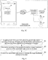
Fig. 1 is a schematic structural diagram illustrating a plant growth control system according to an example embodiment of the present invention; -
Fig. 2A is a schematic structural diagram illustrating a plant growth control system according to another example embodiment of the present invention; -
Fig. 2B is a schematic diagram illustrating positions where light intensity sensors are arranged on a flower pot according to another example embodiment of the present invention; -
Fig. 3A is a schematic structural diagram illustrating a plant growth control system according to still another example embodiment of the present invention; -
Fig. 3B is a schematic diagram illustrating positions of a controllable light source and a target irradiation position relative to each other according to still another example embodiment of the present invention; -
Fig. 3C is a schematic structural diagram illustrating a plant growth control system according to yet still another example embodiment of the present invention; -
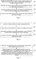
Fig. 4 is a flowchart illustrating a plant growth control method according to an example embodiment of the present invention; -
Fig. 5 is a flowchart illustrating a plant growth control method according to another example embodiment of the present invention; -
Fig. 6 is a flowchart illustrating a plant growth control method according to still another example embodiment of the present invention; and -
Fig. 7 is a flowchart illustrating a method in an alternative solution of the plant growth control method according to yet still another example embodiment of the present invention. - Reference will now be made in detail to example embodiments, examples of which are illustrated in the accompanying drawings. The following description refers to the accompanying drawings in which the same numbers in different drawings represent the same or similar elements unless otherwise represented. The implementations set forth in the following description of example embodiments do not represent all implementations consistent with the present invention. Instead, they are merely examples of systems and methods consistent with aspects related to the present invention as recited in the appended claims.
-
Fig. 1 is a schematic structural diagram illustrating a plant growth control system according to an example embodiment of the present invention. The plant growth control system 100 may comprise: aninformation collector 110, aprocessor 120 connected to theinformation collector 110, and at least one controllablelight source 130. - The
information collector 110 is configured to acquire growth information of a plant, the growth information comprising at least one of branch and leaf distribution information of the plant and flower distribution information of the plant. - The
processor 120 is configured to determine, according to the growth information, a target irradiation position of the controllablelight source 130 in the plant, and to control the controllablelight source 130 to irradiate the target irradiation position in the plant. The controllablelight source 130 refers to a light source which may change its irradiation position in the plant. For example, the controllable light source is rotatable in terms of irradiation direction or movable in terms of position, or the plant is rotatable relative to the position of the controllable light source. - The
processor 120 may be connected to the controllablelight source 130. Optionally, the controllablelight source 130 may be a lamp, and the lamp changes its irradiation direction under control of theprocessor 120. Optionally, the controllablelight source 130 may also be a light source comprising a mechanical part and a lamp. The mechanical part may change its position under control of theprocessor 120, and thus drives the lamp to change its position. The mechanical part may be a mechanical arm, a circular guide rail, a magnetic suspension chassis or the like, which is not limited in this embodiment. In addition,Fig. 1 illustrates the system by using an example in which the controllablelight source 130 is a lamp. - In conclusion, according to the plant growth control system provided by the embodiment of the present invention, growth information of a plant is acquired, a target irradiation position of a controllable light source in the plant is determined according to the growth information, and thus the controllable light source is controlled to irradiate the target irradiation position in the plant. This solves the problem in the related art that a user needs to rotate the flower pot where the plant grows at an interval of a predetermined time period; and achieves the effects of automatically controlling the controllable light source to irradiate a position desiring light irradiation in the plant, and simplifying user's operations.
- In the above embodiment, the plant growth control system may collect relevant information by using a light intensity sensor or a camera and thus acquire growth information of a plant. The
information collector 110 may comprise light intensity sensors or a camera. Therefore, plant growth control systems under such two circumstances where the information collector comprises light intensity sensors and where the information collector comprises a camera are described in different embodiments. -
Fig. 2A is a schematic structural diagram illustrating a plant growth control system according to another example embodiment of the present invention. The system is described in this embodiment using an information collector equipped with at least two light intensity sensors as an example. As illustrated inFig. 2A , the plant growth control system 200 may comprise: an information collector 210, aprocessor 220 connected to the information collector 210, and at least one controllablelight source 230. - The information collector 210 is configured to acquire growth information of a plant, the growth information comprising at least one of branch and leaf distribution information of the plant and flower distribution information of the plant.
- The
processor 220 is configured to determine, according to the growth information, a target irradiation position of the controllablelight source 230 in the plant, and to control the controllablelight source 230 to irradiate the target irradiation position in the plant. The controllablelight source 230 refers to a light source which may change its irradiation position in the plant. For example, the controllable light source is rotatable in terms of irradiation direction or movable in terms of position, or the plant is rotatable relative to the position of the controllable light source. Theprocessor 220 may be connected to the controllablelight source 230. Optionally, the controllablelight source 230 may be a lamp, and the lamp changes its irradiation direction under control of theprocessor 220. Optionally, the controllablelight source 230 may also be a light source comprising a mechanical part and a lamp. The mechanical part may change its position under control of theprocessor 220, and thus drives the lamp to change its position. The mechanical part may be a mechanical arm, a circular guide rail, a magnetic suspension chassis or the like, which is not limited in this embodiment. - Optionally, the
processor 220 may determine the target irradiation position according to the following manners. When the growth information comprises the branch and leaf distribution information, if it is desired that the plant grows more uniformly, theprocessor 220 may determine a side of the plant where a sparse degree of the branch and leaf distribution is less than a first threshold as the target irradiation position (the growth on the side of the plant is promoted by giving more light irradiation to the side). If it is desired that the plant receives more uniform light irradiation, to enable a side of the plant where the branches and leaves are dense to receive light irradiation uniformly, theprocessor 220 may determine a side of the plant where a sparse degree of the branch and leaf distribution is greater than a second threshold as the target irradiation position. When the growth information comprises the flower distribution information, to enable the blooming flowers to receive sufficient light irradiation to ensure better blooming of the flowers, theprocessor 220 may determine a position of the plant where the flowers are blooming as the target irradiation position. If it is desired that a side of the plant where the flowers are still ready to bloom would immediately and more quickly bloom, theprocessor 220 may determine a position of the plant where the flowers are still ready to bloom as the target irradiation position. This embodiment is described only by using the scenario where the processor determines the target irradiation position according to the above manner as an example. Optionally, theprocessor 220 may also determine the target irradiation position according to another manner, which is not limited in this embodiment. - The information collector 210 may comprise at least two light intensity sensors, and each of the light intensity sensors may be configured to acquire a light intensity yielded after ambient light penetrates through the plant. The at least two light intensity sensors are generally arranged at the bottom of the plant. As such, when the ambient light penetrates through the plant and reaches the light intensity sensors arranged at the bottom of the plant, the light intensity sensors may respectively acquire the light intensities. To acquire distributions of the plant in various directions, the at least two light intensity sensors may be evenly arranged around the roots of the plant. In addition, each of the light intensity sensors may be always in a working state. Nevertheless, to prolong the service life of the light intensity sensors, the plant growth control system may further comprise switches for controlling the light intensity sensors. When the growth of the plant needs to be controlled, the switches are turned on and the light intensity sensors are set to the working state.
- After each of the light intensity sensors acquires its corresponding light intensity, the
processor 220 may correspondingly determine the growth information of the plant according to the light intensities acquired by the at least two light intensity sensors. Optionally, the sparser the growth of the plant is, the greater the light intensity yielded after the ambient light penetrates through the plant is; and the denser the growth of the plant is, the less the light intensity yielded after the ambient light penetrates through the plant is. Therefore, after theprocessor 220 obtains the light intensities, theprocessor 220 may determine the side corresponding to the light intensity sensor which collects a weak light intensity in the plant as a dense side, and determine the side corresponding to the light intensity sensor which collects a strong light intensity in the plant as a sparse side. Theprocessor 220 may determine the branch and leaf distribution information of the plant. Optionally, the more the light intensity sensors are provided, the more accurate the determined distribution information of the plant is. Therefore, in practical implementation, the number of light intensity sensors may be defined according to actual needs, which is not limited in this embodiment. - Optionally, the plant growth control system may further comprise a flower pot, and at least two light intensity sensors may be arranged on the edge of the flower pot.
- The at least two light intensity sensors may be evenly arranged on the edge of the flower pot. For example, using four light intensity sensors as an example, the flower pot is divided into four regions in the unit of 90 degrees, and the four light intensity sensors may be arranged in the flower pot at four positions A, B, C and D as illustrated in
Fig. 2B . In addition, each of the light intensity sensors may be integrated sensors of the flower pot; or the flower pot and the light intensity sensors may be two independent parts, and before use, a user may install the light intensity sensors on the edge of the flower pot, which is not limited in this embodiment. - Optionally, in order to control the controllable
light source 230 to irradiate the target irradiation position in the plant, the controllablelight source 230 in the plant growth control system may be in a moving state or a stationary state under control of theprocessor 220. For example, after theprocessor 220 determines the target irradiation position, theprocessor 220 may control the controllablelight source 230 to move, and thus cause the irradiation position of the controllablelight source 230 to move to the target irradiation position in the plant. - Herein the movement may be movement made by the controllable
light source 230 via rotating at an angle. For example, the controllablelight source 230 may be a head-rotatable lamp (similar to a swing camera), theprocessor 220 may control rotation of the lamp head to thus control the lamp to move. Alternatively, theprocessor 220 may also control movement of the position of the controllablelight source 230. For example, the controllablelight source 230 may be a suspension lamp, and the suspension lamp may change its suspension position under control of theprocessor 220. However, this embodiment sets no limitation thereto. - In this embodiment, the controllable
light source 230 may be a lamp or a lamp seat (the lamp seat is used for mounting the light bulb). The lamp may be a suspension lamp, a ceiling lamp, or a table lamp. The lamp may be in red, white, yellow, green or any other color. In addition, when the lamp is a suspension lamp, the plant growth control system may further comprise a suspension system (the suspension system may comprise a system located at the lower part of the suspension lamp, or a system located at the top part of the suspension lamp, or both the systems at the lower and top parts) corresponding to the suspension lamp, and theprocessor 220 may move the suspension lamp by moving the suspension system. In addition, the number of controllable light sources may be one, or may be two or more. When there are two or more controllable light sources, theprocessor 220 may selectively control one or a plurality of the controllable light sources to irradiate the target irradiation position in the plant. Optionally, the plurality of controllable light sources may be in the same color or different colors, which is not limited in this embodiment. - Optionally, when the
processor 220 may control the controllablelight source 230 to be in a moving state or a stationary state, the process that theprocessor 220 controls the controllablelight source 230 to irradiate the target irradiation position in the plant may be implemented according to any one of the following two manners: - (1) The controllable light source in an ON state is controlled to rotate, and rotation of the controllable light source is stopped when the light intensity sensor corresponding to the target irradiation position acquires a light intensity greater than a predetermined light intensity.
When the controllablelight source 230 is a rotatable light source, theprocessor 220 may control the controllablelight source 230 in the ON state to rotate (each of the light intensity sensors collects a light intensity in real time). When the light intensity acquired by the light intensity sensor corresponding to the target irradiation position is greater than a predetermined light intensity, the controllablelight source 230 approximately moves to the target irradiation position. In this case, theprocessor 220 may control the controllablelight source 230 to stop rotating.
The light intensity sensor corresponding to the target irradiation position is the light intensity sensor based on which the target irradiation position is determined. For example, by using as an example a scenario where theprocessor 220 determines a side (that is the position corresponding to the light intensity sensor which acquires the greatest light intensity among all the light intensity sensors) of the plant where a sparse degree of the branch and leaf distribution is less than a first threshold as the target irradiation position, the light intensity sensor corresponding to the target irradiation position is the light intensity sensor which historically acquires the greatest light intensity. - (2) The controllable light source in an ON state is controlled to move, and movement of the controllable light source is stopped when the light intensity sensor corresponding to the target irradiation position acquires a light intensity greater than a predetermined light intensity.
- When the controllable
light source 230 is a movable light source, theprocessor 220 may control the controllablelight source 230 in the ON state to move. When the light intensity acquired by the light intensity sensor corresponding to the target irradiation position is greater than a predetermined light intensity, the controllablelight source 230 approximately moves to the target irradiation position. In this case, theprocessor 220 may control the controllablelight source 230 to stop moving. - The light intensity sensor corresponding to the target irradiation position is the light intensity sensor based on which the target irradiation position is determined.
- It should be noted that the above description is given only by using as an example the scenario where when the light intensity acquired by the light intensity sensor corresponding to the target irradiation position is greater than a predetermined light intensity, the processor stops movement of the controllable light source. Optionally, the processor may also stop movement of the controllable light source when the light intensity sensor corresponding to the target irradiation position acquires a light intensity greater than a historically acquired light intensity, which is not limited in this embodiment. In addition, if the initial state of the controllable
light source 230 is an OFF state, theprocessor 220 needs to put in the ON state the controllablelight source 230 before moving the same. - Optionally, the plant growth control system may further comprise a base for accommodating the flower pot, wherein the base may be electrically connected to the
processor 220, and the base may be in a rotation state or a stationary state under control of theprocessor 220. When the base rotates, the flower pot disposed on the base may correspondingly rotate. For example, after theprocessor 220 determines the target irradiation position, theprocessor 220 may control the base to rotate to thus drive the flower pot to rotate. As such, the target irradiation position of the plant in the flower pot moves below the light source. - Optionally, when the base may be in a rotation state or a stationary state under control of the
processor 220, the process that theprocessor 220 controls the controllablelight source 230 to irradiate the target irradiation position in the plant may be implemented according to the following manners: - Controlling the flower pot where the plant grows to rotate, and stopping rotation of the flower pot when the light intensity sensor corresponding to the target irradiation position acquires a light intensity greater than a predetermined light intensity. The
processor 220 may control the base to rotate (the rotation of the base may drive the flower pot thereon to rotate as well, that is, the plant in the flower pot may also rotate). When the light intensity acquired by the light intensity sensor corresponding to the target irradiation position is greater than a predetermined light intensity, the target irradiation position of the plant is substantially below the light source. In this case, theprocessor 220 may stop rotating the base (that is, stop rotating the flower pot). - This embodiment is described only by using the scenario where the controllable
light source 230 stays in a moving state or a stationary state under control of theprocessor 220, or the base stays in a rotation state or a stationary state under control of theprocessor 220 as an example. Optionally, the controllablelight source 230 and the base may both move or rotate under control of theprocessor 220, which is not limited in this embodiment. - It should be noted that, the plant growth control system in this embodiment may be a battery powered system or a system connected to a power socket for power supply. In addition, when the system is a system connected to a power socket for power supply, the system may further comprise a connection wire and a plug for connecting the socket. This embodiment sets no limitation thereto. In addition, when the light source is a suspension lamp, the suspension lamp may also be a wirelessly-chargeable lamp, which is not limited in this embodiment.
- In conclusion, according to the plant growth control system provided by the embodiment of the present invention, growth information of a plant is acquired, a target irradiation position of a controllable light source in the plant is determined according to the growth information, and thus the controllable light source is controlled to irradiate the target irradiation position in the plant. This solves the problem in the related art that a user needs to rotate the flower pot where the plant grows at an interval of a predetermined time period; and achieves the effects of automatically controlling the controllable light source to irradiate a position desiring light irradiation in the plant, and simplifying user's operations.
-
Fig. 3A is a schematic structural diagram illustrating a plant growth control system according to still another example embodiment of the present invention. The system is described in this embodiment by using an information collector equipped with a camera as an example. As illustrated inFig. 3A , the plant growth control system 300 may comprise: aninformation collector 310, aprocessor 320 connected to theinformation collector 310, and at least one controllablelight source 330. - The
information collector 310 is configured to acquire growth information of a plant, the growth information comprising at least one of branch and leaf distribution information of the plant and flower distribution information of the plant. - The
processor 320 is configured to determine, according to the growth information, a target irradiation position of the controllablelight source 330 in the plant, and to control the controllable light source to irradiate the target irradiation position in the plant. The controllablelight source 330 is a light source which may change its irradiation position in the plant. For example, the controllable light source is rotatable in terms of irradiation direction or movable in terms of position. The relevant features of the controllablelight source 330 are similar to those of the controllable light source described in the above embodiment, which are thus not described herein any further. - Optionally, the
processor 320 may determine the target irradiation position according to the following manners. When the growth information comprises the branch and leaf distribution information, if it is desired that the plant grows more uniformly, theprocessor 320 may determine a side of the plant where a sparse degree of the branch and leaf distribution is less than a first threshold as the target irradiation position, and thus the growth on the side of the plant is promoted by giving more irradiation to the side. If it is desired that the plant receives more uniform light irradiation, to enable a side where the branches and leaves are dense to receive light irradiation uniformly, theprocessor 320 may determine a side of the plant where a sparse degree of the branch and leaf distribution is greater than a second threshold as the target irradiation position. When the growth information comprises the flower distribution information, to enable the blooming flowers to receive sufficient light irradiation to ensure better blooming of the flowers, theprocessor 320 may determine a position of the plant where the flowers are blooming as the target irradiation position. If it is desired that a side of the plant where the flowers are still ready to bloom would immediately and more quickly bloom, theprocessor 320 may determine the position of the plant where the flowers are still ready to bloom as the target irradiation position. This embodiment is described only by using the scenario where the processor determines the target irradiation position according to the above manner as an example. Optionally, theprocessor 320 may also determine the target irradiation position according to another manner, which is not limited in this embodiment. - The
information collector 310 may comprise a camera. The camera is configured to acquire an image containing the plant. Optionally, the information collector may comprise one or a plurality of cameras. When there is only one camera, the position of the camera may be higher than the plant. As such, the camera may acquire a full-view image containing the plant. Nevertheless, the position of the camera may also be as high as the plant. In this case, the flower pot where the plant grows may be constantly rotated such that the camera acquires a plurality of frames of images containing the plant. In addition, when there are a plurality of cameras, the plurality of cameras may acquire images containing the plant from different angles and points of view. - After the camera acquires the image containing the plant, the
processor 320 may acquire the growth information of the plant according to the image. Optionally, theprocessor 320 may conduct an image analysis on the acquired image, thus obtain the branch and leaf distribution, blooming flower distribution or both, and use the obtained analysis result as the growth information of the plant. - Optionally, to control the controllable
light source 330 to irradiate the target irradiation position in the plant, the controllablelight source 330 in the plant growth control system may be in a moving state or a stationary state under control of theprocessor 320. - When the
processor 320 may control the controllablelight source 330 to stay in a moving state or a stationary state, the process that theprocessor 320 controls the controllablelight source 330 to irradiate the target irradiation position in the plant may be implemented according to the following manners: - First, positions of the controllable light source and the target irradiation position relative to each other are determined according to the image.
Firstly, to acquire the position of the controllablelight source 330, the image containing the plant acquired by the camera in this embodiment needs to cover the controllablelight source 330. In this way, after acquiring the images, theprocessor 320 may analyze the image containing the plant and the controllablelight source 330 to obtain positions of the controllablelight source 330 and the target irradiation position in the plant relative to each other. - Second, an adjustment angle desired for the controllable light source is determined according to the relative positions.
- The plant growth control system may pre-store several candidate adjustment angles, for example, clockwise adjustment angles of 90 degrees, 180 degrees and 270 degrees. After determining the relative positions, the
processor 320 selects an adjustment angle closest to the target angle from all the candidate adjustment angles. The target angle is a precise angle by which the current position of the light source is adjusted to the target irradiation position. By using a scenario where there is only one controllablelight source 330, and where the camera acquires the image as illustrated inFig.3B as an example, theprocessor 320 may determine that the controllablelight source 330 needs to be clockwise adjusted by 90 degrees according to the relative positions of the controllablelight source 330 and the target irradiation position (position A in the drawing). - This embodiment is described by using a scenario where the
processor 320 determines the adjustment angle by the above method as an example. Optionally, theprocessor 320 may also calculate, according to the relative positions, the angle by which the controllablelight source 330 is adjusted to a central position of the target irradiation position, and determine the calculated angle as the adjustment angle, which is not limited in this embodiment. - Third, the controllable light source is adjusted according to the adjustment angle.
- After determining the adjustment angle, the
processor 320 may move the controllablelight source 330 by the determined adjustment angle, for example, clockwise movement by 90 degrees. - Optionally, the plant growth control system may further comprise a base for accommodating the flower pot, wherein the base may be electrically connected to the
processor 320, and the base may be in a rotation state or a stationary state under control of theprocessor 320. When the base rotates, the flower pot disposed on the base may correspondingly rotate. - Optionally, when the base may be in a rotation state or a stationary state under control of the
processor 320, the process that theprocessor 320 controls the controllablelight source 330 to irradiate the target irradiation position in the plant may be implemented according to the following manners: - First, positions of the controllable light source and the target irradiation position relative to each other are determined according to the image.
- Second, an adjustment angle desired for the flower pot where the plant grows is determined according to the relative positions.
This is similar to the manner of determining the adjustment angle desired by the controllablelight source 330 described above, which is thus not described herein any further. - Third, the flower pot is adjusted according to the adjustment angle.
- This is similar to the implementation in the above embodiment, which is thus not described herein any further.
- This embodiment is described only by using the scenario where the controllable
light source 330 stays in a moving state or a stationary state under control of theprocessor 320, or the base stays in a rotation state or a stationary state under control of theprocessor 320 as an example. Optionally, the controllablelight source 330 and the base may both move or rotate under control of theprocessor 320, which is not limited in this embodiment. - It should be noted that, the plant growth control system in this embodiment may be a battery powered system or a system connected to a power socket for power supply. In addition, when the system is a system connected to a power socket for power supply, the system may further comprise a connection wire and a plug for connecting the socket. This embodiment sets no limitation thereto. In addition, when the light source is a suspension lamp, the suspension lamp may also be a wirelessly-chargeable lamp, which is not limited in this embodiment.
- In conclusion, according to the plant growth control system provided by the embodiment of the present invention, growth information of a plant is acquired, a target irradiation position of a controllable light source in the plant is determined according to the growth information, and thus the controllable light source is controlled to irradiate the target irradiation position in the plant. This solves the problem in the related art that a user needs to rotate the flower pot where the plant grows at an interval of a predetermined time period; and achieves the effects of automatically controlling the controllable light source to irradiate a position desiring light irradiation in the plant, and simplifying user's operations.
- It should be supplemented that in the above various embodiments, the plant growth control system may further comprise a human body infrared sensor, wherein the human body infrared sensor may be electrically connected to the processor. The human body infrared sensor is configured to detect a human body infrared signal in an environment.
- Correspondingly, the processor is further configured to, when the human body infrared sensor detects a human body infrared signal, control the controllable light source in a predetermined control manner and/or control the flower pot where the plant grows to rotate, the predetermined control manner comprising adjusting luminance of the controllable light source or controlling the controllable light source to blink.
- When someone approaches a plant, the human body infrared sensor in the plant growth control system may detect a human body infrared signal. At this time, the processor may increase the luminance of the light source, or control the light source to blink, or control the base of the flower pot to rotate, which brings a dazzling visual experience to a user, and greatly improves the user experience. In particular, when there are a plurality of controllable light sources, and the color of each light source is different from another, this will undoubtedly create a very dazzling visual experience to the user.
- In an application scenario of this embodiment, the controllable light source is formed of a plurality of magnetic suspension lamps, the colors of the magnetic suspension lamps are different, and each magnetic suspension lamp may move under control of the processor. As such, when the human body infrared sensor detects a human body infrared signal, these magnetic suspension lamps may stay in a rotatary movement state under control of the processor. When the magnetic suspension lamps are rotating, a stunning visual feast is definitely brought to the user.
- It should be supplemented that, referring to
Fig. 3C , theprocessor 120 in the plant growth control system in the above embodiments may be a processor in a smart terminal. Theprocessor 120 may receive a control instruction from a user, and perform a corresponding operation according to the received control instruction. The control instruction is used to control the controllable light source to move or control the flower pot to rotate. Optionally, when the control instruction is used to control the controllable light source to move, theprocessor 120 may establish a wireless connection with an information transceiver apparatus of the controllable light source via an information transceiver in the smart terminal, send the control instruction to the controllablelight source 130 via the established wireless connection, and thus control the controllablelight source 130. As such, a user may remotely control growth of the plant by using his or her smart terminal, thereby improving the user experience. - Optionally, when the processor is a processor in a smart terminal, the processor may also be wirelessly connected to the information collector by using an information transceiver in the smart terminal, receive the information collected by the information collector, and process the received information, which is not limited in this embodiment.
-
Fig. 4 is a flowchart illustrating a plant growth control method according to an example embodiment of the present invention. The plant growth control method may be performed by the plant growth control system as illustrated inFig. 1 . As illustrated inFig. 4 , the plant growth control method may comprise the following steps. - In
step 401, growth information of a plant is acquired, wherein the growth information comprises at least one of branch and leaf distribution information of the plant and flower distribution information of the plant. - In
step 402, a target irradiation position of the controllable light source in the plant is determined according to the growth information. - In
step 403, the controllable light source is controlled to irradiate the target irradiation position in the plant. - In conclusion, according to the plant growth control method provided by the embodiment of the present invention, growth information of a plant is acquired, a target irradiation position of a controllable light source in the plant is determined according to the growth information, and thus the controllable light source is controlled to irradiate the target irradiation position in the plant. This solves the problem in the related art that a user needs to rotate the flower pot where the plant grows at an interval of a predetermined time period; and achieves the effects of automatically controlling the controllable light source to irradiate a position desiring light irradiation in the plant, and simplifying user's operations.
- Since the plant growth control system may collect relevant information by using a light intensity sensor or a camera and thus acquire growth information of a plant, the plant growth control methods under such two circumstances where the information collector comprises light intensity sensors and comprises a camera are described in different embodiments.
-
Fig. 5 is a flowchart illustrating a plant growth control method according to an example embodiment of the present invention. The plant growth control method may be performed by the plant growth control system as illustrated inFig. 2A . As illustrated inFig. 5 , the plant growth control method may comprise the following steps. - In
step 501, light intensities yielded after ambient light penetrates through the plant are respectively acquired by using at least two light intensity sensors arranged at the bottom of the plant. - In
step 502, the growth information of the plant is determined according to at least two light intensities acquired. - The growth information comprises at least one of branch and leaf distribution information of the plant and flower distribution information of the plant.
- In
step 503, a target irradiation position of the controllable light source in the plant is determined according to the growth information. - Optionally, this step may comprise:
- when the growth information comprises the branch and leaf distribution information, determining a side of the plant where a sparse degree of the branch and leaf distribution is less than a first threshold as the target irradiation position of the controllable light source, or determining a side of the plant where a sparse degree of the branch and leaf distribution is greater than a second threshold as the target irradiation position of the controllable light source; and
- when the growth information comprises the flower distribution information, determining a side of the plant where flowers are blooming as the target irradiation position of the controllable light source.
- In
step 504, the controllable light source is controlled to irradiate the target irradiation position in the plant. - Optionally, this step may comprise the following three possible implementation manners:
- First, the controllable light source in an ON state is controlled to rotate, and rotation of the controllable light source is stopped when the light intensity sensor corresponding to the target irradiation position acquires a light intensity greater than a predetermined light intensity.
- Second, the controllable light source in an ON state is controlled to move, and movement of the controllable light source is stopped when the light intensity sensor corresponding to the target irradiation position acquires a light intensity greater than a predetermined light intensity.
- Third, the flower pot where the plant grows is controlled to rotate, and rotation of the flower pot is stopped when the light intensity sensor corresponding to the target irradiation position acquires a light intensity greater than a predetermined light intensity.
- In conclusion, according to the plant growth control method provided by the embodiment of the present invention, growth information of a plant is acquired, a target irradiation position of a controllable light source in the plant is determined according to the growth information, and thus the controllable light source is controlled to irradiate the target irradiation position in the plant. This solves the problem in the related art that a user needs to rotate the flower pot where the plant grows at an interval of a predetermined time period; and achieves the effects of automatically controlling the controllable light source to irradiate a position desiring light irradiation in the plant, and simplifying user's operations.
-
Fig. 6 is a flowchart illustrating a plant growth control method according to an example embodiment of the present invention. The plant growth control method may be performed by the plant growth control system as illustrated inFig. 3A . As illustrated inFig. 6 , the plant growth control method may comprise the following steps. - In
step 601, an image containing the plant is acquired by using a camera. - In
step 602, the growth information of the plant is acquired according to the image. - The growth information comprises at least one of branch and leaf distribution information of the plant and flower distribution information of the plant.
- In
step 603, a target irradiation position of the controllable light source in the plant is determined according to the growth information. - When the growth information comprises the branch and leaf distribution information, a side of the plant where a sparse degree of the branch and leaf distribution is less than a first threshold is determined as the target irradiation position of the controllable light source, or a side of the plant where a sparse degree of the branch and leaf distribution is greater than a second threshold is determined as the target irradiation position of the controllable light source.
- When the growth information comprises the flower distribution information, a side of the plant where flowers are blooming is determined as the target irradiation position of the controllable light source.
- In
step 604, the controllable light source is controlled to irradiate the target irradiation position in the plant. - Optionally, this step may comprise:
- first, determining positions of the controllable light source and the target irradiation position relative to each other according to the image;
- second, determining, according to the relative positions, an adjustment angle desired for the controllable light source or the flower pot where the plant grows; and
- third, adjusting the controllable light source or the flower pot according to the adjustment angle.
- In conclusion, according to the plant growth control method provided by the embodiment of the present invention, growth information of a plant is acquired, a target irradiation position of a controllable light source in the plant is determined according to the growth information, and thus the controllable light source is controlled to irradiate the target irradiation position in the plant. This solves the problem in the related art that a user needs to rotate the flower pot where the plant grows at an interval of a predetermined time period; and achieves the effects of automatically controlling the controllable light source to irradiate a position desiring light irradiation in the plant, and simplifying user's operations.
- It should be noted that, referring to
Fig. 7 , in the above various embodiments, the plant growth control method may further comprise the following steps. - In
step 701, a human body infrared signal in an environment is detected by using a human body infrared sensor. - In
step 702, when a human body infrared signal is detected, the controllable light source is controlled in a predetermined control manner and/or the flower pot where the plant grows is controlled to rotate, wherein the predetermined control manner comprises adjusting luminance of the controllable light source or controlling the controllable light source to blink. - When someone approaches a plant, the human body infrared sensor in the plant growth control system may detect a human body infrared signal. At this time, the processor may increase the luminance of the controllable light source, or control the controllable light source to blink, or control the base of the flower pot to rotate, which brings a dazzling visual experience to a user, and greatly improves the user experience. In particular, when there are a plurality of light sources, and the color of each light source is different from another, this will undoubtedly create a very dazzling visual experience to the user.
- It should be supplemented that, the processor in the plant growth control system may be a processor in a smart terminal. The processor may receive a control instruction from a user, and perform a corresponding operation according to the received control instruction. The control instruction is used to control the light source to move or control the flower pot to rotate. As such, a user may remotely control growth of the plant by using his or her smart terminal, thereby improving the user experience.
- It will be appreciated that the present invention is not limited to the exact construction that has been described above and illustrated in the accompanying drawings, and that various modifications and changes can be made without departing from the scope thereof. The scope of the present invention is only defined by the appended claims.
Claims (16)
- A plant growth control system (100, 200, 300), comprising: an information collector (110, 210, 310), a processor (120, 220, 320) connected to the information collector (110, 210, 310), and a controllable light source (130, 230, 330); wherein
the information collector (110, 210, 310) is configured to acquire growth information of a plant, the growth information comprising at least one of branch and leaf distribution information of the plant and flower distribution information of the plant; and
the processor (120, 220, 320) is configured to determine, according to the growth information, a target irradiation position of the controllable light source (130, 230, 330) in the plant, and to control the controllable light source (130, 230, 330) to irradiate the target irradiation position in the plant. - The system according to claim 1, wherein the information collector (210) comprises at least two light intensity sensors; wherein
the light intensity sensors are configured to acquire light intensities yielded after ambient light penetrates through the plant; and
the processor (220) is further configured to determine the growth information of the plant according to the light intensities acquired by the at least two light intensity sensors. - The system according to claim 1 or 2, wherein the system (200) further comprises a flower pot, wherein the at least two light intensity sensors are arranged on the edge of the flower pot.
- The system according to claim 1, wherein the information collector (310) comprises a camera; wherein
the camera is configured to acquire an image containing the plant; and
the processor (320) is further configured to acquire the growth information of the plant according to the image. - The system according to any one of claims 1 to 4, wherein the controllable light source (230, 330) is in a moving state or a stationary state under control of the processor (220, 320).
- The system according to any one of claims 1 to 5, wherein the system (200, 300) further comprises a base for accommodating the flower pot, wherein the base is in a rotation state or a stationary state under control of the processor (220, 320).
- The system according to any one of claims 1 to 6, wherein the system (100, 200, 300) further comprises a human body infrared sensor; wherein
the human body infrared sensor is configured to detect a human body infrared signal in an environment; and
the processor (120, 220, 320) is further configured to, when the human body infrared sensor detects the human body infrared signal, control the controllable light source (130, 230, 330) in a predetermined control manner and/or control the flower pot where the plant grows to rotate, the predetermined control manner comprising adjusting luminance of the controllable light source (130, 230, 330) or controlling the controllable light source (130, 230, 330) to blink. - A plant growth control method, wherein the method is performed by the plant growth control system (100, 200, 300) according to any one of claims 1 to 7, wherein the method comprises:acquiring (401, 502, 602) growth information of a plant, the growth information comprising at least one of branch and leaf distribution information of the plant and flower distribution information of the plant;determining (402, 503, 603), according to the growth information, a target irradiation position of the controllable light source in the plant; andcontrolling (403, 504, 604) the controllable light source to irradiate the target irradiation position in the plant.
- The method according to claim 8, wherein the step of acquiring growth information of a plant comprises:acquiring (501), by using at least two light intensity sensors arranged at the bottom of the plant, light intensities yielded after ambient light penetrates through the plant; anddetermining (502) the growth information of the plant according to at least two light intensities acquired.
- The method according to claim 8 or 9, wherein the step of controlling (504, 604) the controllable light source to irradiate the target irradiation position in the plant comprises:controlling the controllable light source in an ON state to rotate, and stopping rotation of the controllable light source when the light intensity sensor corresponding to the target irradiation position acquires a light intensity greater than a predetermined light intensity;
orcontrolling the controllable light source in an ON state to move, and stopping movement of the controllable light source when the light intensity sensor corresponding to the target irradiation position acquires a light intensity greater than a predetermined light intensity;
orcontrolling the flower pot where the plant grows to rotate, and stopping rotation of the flower pot when the light intensity sensor corresponding to the target irradiation position acquires a light intensity greater than a predetermined light intensity. - The method according to claim 8, wherein the step of acquiring growth information of a plant comprises:acquiring (601), by using a camera, an image containing the plant; andacquiring (602) the growth information of the plant according to the image.
- The method according to claim 8 or 11, wherein the image further contains the controllable light source, and the step of controlling (604) the controllable light source to irradiate the target irradiation position in the plant comprises:determining positions of the controllable light source and the target irradiation position relative to each other according to the image;determining, according to the relative positions, an adjustment angle desired for the controllable light source or the flower pot where the plant grows; andadjusting the controllable light source or the flower pot according to the adjustment angle.
- The method according to any one of claims 8 to 12, wherein the step of determining (503, 603), according to the growth information, a target irradiation position of the controllable light source in the plant comprises:when the growth information comprises the branch and leaf distribution information, determining a side of the plant where a sparse degree of the branch and leaf distribution is less than a first threshold as the target irradiation position of the controllable light source, or determining a side of the plant where a sparse degree of the branch and leaf distribution is greater than a second threshold as the target irradiation position of the controllable light source; andwhen the growth information comprises the flower distribution information, determining a side of the plant where flowers are blooming as the target irradiation position of the controllable light source.
- The method according to any one of claims 8 to 13, wherein the method further comprises:detecting (701), by using a human body infrared sensor, a human body infrared signal in an environment; andwhen the human body infrared signal is detected, controlling (702) the controllable light source in a predetermined control manner and/or controlling the flower pot where the plant grows to rotate, the predetermined control manner comprising adjusting luminance of the controllable light source or controlling the controllable light source to blink.
- A computer program, including instructions for executing the steps of a plant growth control method according to any one of claims 8 to 14 when said program is executed by a computer.
- A recording medium readable by a computer and having recorded thereon a computer program including instructions for executing the steps of a plant growth control method according to any one of claims 8 to 14.
Applications Claiming Priority (1)
| Application Number | Priority Date | Filing Date | Title |
|---|---|---|---|
| CN201510145989.XA CN104898468B (en) | 2015-03-31 | 2015-03-31 | plant growth control system and method |
Publications (2)
| Publication Number | Publication Date |
|---|---|
| EP3075231A1 true EP3075231A1 (en) | 2016-10-05 |
| EP3075231B1 EP3075231B1 (en) | 2019-07-17 |
Family
ID=54031186
Family Applications (1)
| Application Number | Title | Priority Date | Filing Date |
|---|---|---|---|
| EP16158688.8A Active EP3075231B1 (en) | 2015-03-31 | 2016-03-04 | Plant growth control system and method |
Country Status (8)
| Country | Link |
|---|---|
| US (1) | US20160286732A1 (en) |
| EP (1) | EP3075231B1 (en) |
| JP (1) | JP2017513534A (en) |
| KR (1) | KR20160127626A (en) |
| CN (1) | CN104898468B (en) |
| MX (1) | MX373482B (en) |
| RU (1) | RU2630942C2 (en) |
| WO (1) | WO2016155224A1 (en) |
Families Citing this family (20)
| Publication number | Priority date | Publication date | Assignee | Title |
|---|---|---|---|---|
| US9986621B2 (en) * | 2016-01-22 | 2018-05-29 | Lumigrow, Inc. | Lighting system for growing plants which provides a location indication |
| US10660170B2 (en) * | 2016-01-22 | 2020-05-19 | Lumigrow, Inc. | Lighting system for growing plants |
| CN105929880A (en) * | 2016-06-30 | 2016-09-07 | 沈焱 | Plant growth monitoring and environment control System for enclosed environment |
| CN106242063A (en) * | 2016-08-26 | 2016-12-21 | 武汉中科水生环境工程股份有限公司 | A kind of light compensates potent in-situ purification of water body floating bed |
| CN106375711A (en) * | 2016-08-29 | 2017-02-01 | 深圳前海弘稼科技有限公司 | Control method and control device for planting equipment, and planting equipment |
| US20180220592A1 (en) * | 2017-02-03 | 2018-08-09 | Argia Group Llc | Method and system for plant growth lighting |
| CN107908198B (en) * | 2017-11-17 | 2020-11-03 | 福建农林大学 | Illumination shaping guide system and method for plant bonsai |
| US11464173B2 (en) * | 2018-02-28 | 2022-10-11 | Aessense Technology Hong Kong Limited | Horticultural system with closed-loop light control |
| CN109121809A (en) * | 2018-09-26 | 2019-01-04 | 济南新吉纳远程测控股份有限公司 | A kind of electricity saving method and its device, application for cultivating plant by artificial light source |
| EP3650844A1 (en) * | 2018-11-09 | 2020-05-13 | B&R Industrial Automation GmbH | Illumination device for illuminating an at least one area monitored by an image sensor |
| KR102047539B1 (en) * | 2018-11-26 | 2019-11-21 | 농업회사법인 유한회사 식물공장 | Vertical hanging bed |
| KR102130453B1 (en) * | 2020-01-20 | 2020-07-08 | (주)엘앤피 | Smart lighting apparatus and method for planting |
| CN111642266A (en) * | 2020-07-06 | 2020-09-11 | 安徽理工大学 | A hanging multifunctional plant light supplement device |
| CN111990101B (en) * | 2020-09-09 | 2023-08-01 | 安徽世林照明股份有限公司 | Intelligent control vegetation lamp for big-arch shelter |
| CN113196999A (en) * | 2021-04-22 | 2021-08-03 | 常州纺织服装职业技术学院 | Indoor plant illumination control method and device |
| CN113207212B (en) * | 2021-04-22 | 2022-12-16 | 常州纺织服装职业技术学院 | A lighting control method and device for guiding plant growth direction |
| JP7448826B2 (en) * | 2021-06-25 | 2024-03-13 | 東芝情報システム株式会社 | Light irradiation leveling system |
| CN113847566B (en) * | 2021-09-24 | 2023-09-12 | 中国农业科学院都市农业研究所 | Light conversion unit and method for multi-degree-of-freedom rotary light source |
| US20230172115A1 (en) * | 2021-12-08 | 2023-06-08 | Eden Green US & Caribbean Produce Holdings Inc. | Lighting system and method for use in vertical hydroponics |
| CN114384954B (en) * | 2022-01-10 | 2023-05-23 | Tcl通讯科技(成都)有限公司 | Container control method, apparatus, container, and computer-readable storage medium |
Citations (4)
| Publication number | Priority date | Publication date | Assignee | Title |
|---|---|---|---|---|
| FR2762198A3 (en) * | 1997-04-22 | 1998-10-23 | Louis Limousin | Rotating display stand for plants |
| WO2011068182A1 (en) * | 2009-12-03 | 2011-06-09 | Okazaki Seiichi | Plant cultivation system |
| DE102011105147B3 (en) * | 2011-06-09 | 2012-11-22 | Deutsches Zentrum für Luft- und Raumfahrt e.V. | Method for illuminating plants in greenhouses and illuminating private homes artificially, involves acquiring image data of plant with camera, and detecting surface of plant |
| CN203309650U (en) * | 2013-07-16 | 2013-11-27 | 大连工大(泗阳)光源与照明工程技术研究院有限公司 | Intelligent LED (light-emitting diode) light-supplementing table lamp for plants |
Family Cites Families (20)
| Publication number | Priority date | Publication date | Assignee | Title |
|---|---|---|---|---|
| RU2122316C1 (en) * | 1993-08-31 | 1998-11-27 | Малое предприятие "Патент" Государственного научно-исследовательского и проектного института "Гипронисельпром" | Greenhouse |
| KR100414641B1 (en) * | 2000-04-07 | 2004-01-13 | 동부한농화학 주식회사 | In vivo monitoring method of transgenic plants and system using the same |
| CN1507770A (en) * | 2002-12-18 | 2004-06-30 | 薛留芳 | Method for breeding Rohdea japonica with special shape |
| JP2005295955A (en) * | 2004-04-15 | 2005-10-27 | Osaka Industrial Promotion Organization | Plant growing device |
| KR20100014558A (en) * | 2007-03-23 | 2010-02-10 | 헬리오스펙트라 악티볼라그 | System that regulates plant growth or properties |
| JP2009028491A (en) * | 2007-06-22 | 2009-02-12 | Panasonic Electric Works Co Ltd | Shelf lighting system and shelf unit lighting system |
| CN102088840B (en) * | 2008-07-11 | 2014-03-05 | 皇家飞利浦电子股份有限公司 | Illumination arrangement for illuminating horticultural growths |
| JP2011045286A (en) * | 2009-08-27 | 2011-03-10 | Institute Of National Colleges Of Technology Japan | Device and method for controlling growth of plant |
| JP5424993B2 (en) * | 2010-06-17 | 2014-02-26 | パナソニック株式会社 | Lighting device for plant disease control |
| CN103238058A (en) * | 2010-12-02 | 2013-08-07 | 日本电气株式会社 | Leaf area index measurement system, equipment, method and program |
| WO2012102372A1 (en) * | 2011-01-27 | 2012-08-02 | 公立大学法人大阪府立大学 | Plant cultivation method and plant cultivation device |
| US10767839B2 (en) * | 2012-03-30 | 2020-09-08 | Dow Agrosciences Llc | Lighting system |
| TWI510183B (en) * | 2012-04-20 | 2015-12-01 | Univ Nat Ilan | Automatic controlled mechanism of adjusting the light position by detecting the canopy height of plants |
| CN102835262A (en) * | 2012-08-23 | 2012-12-26 | 广东朗视光电技术有限公司 | A LED plant growth promotion system |
| CN104582472B (en) * | 2012-09-04 | 2018-06-05 | 飞利浦灯具控股公司 | Horticultural lighting system and horticultural production facility using the horticultural lighting system |
| CN103782825A (en) * | 2012-11-03 | 2014-05-14 | 西安道恒交通设备科技有限公司 | Flowerpot for balancing flower lighting |
| CN103782826A (en) * | 2012-11-03 | 2014-05-14 | 西安道恒交通设备科技有限公司 | Flower pot capable of controlling plants to be lighted in a balanced manner |
| CN103250600B (en) * | 2013-05-07 | 2015-02-25 | 南京农业大学 | Intelligent LEDs lamp holder adjusting and controlling system for plant factory cultivation frame |
| CN103563685B (en) * | 2013-11-25 | 2015-02-11 | 江苏大学 | Self-adaptive light supplementing system and method for plant factory |
| CN104359049B (en) * | 2014-11-03 | 2017-07-21 | 中国农业科学院农业环境与可持续发展研究所 | Plant artificial light cultivates intelligent accurate lighting energy saving method and its device |
-
2015
- 2015-03-31 CN CN201510145989.XA patent/CN104898468B/en active Active
- 2015-08-31 KR KR1020157030890A patent/KR20160127626A/en not_active Ceased
- 2015-08-31 JP JP2017508735A patent/JP2017513534A/en active Pending
- 2015-08-31 MX MX2016000594A patent/MX373482B/en active IP Right Grant
- 2015-08-31 RU RU2016101262A patent/RU2630942C2/en active
- 2015-08-31 WO PCT/CN2015/088628 patent/WO2016155224A1/en not_active Ceased
-
2016
- 2016-03-04 EP EP16158688.8A patent/EP3075231B1/en active Active
- 2016-03-28 US US15/083,222 patent/US20160286732A1/en not_active Abandoned
Patent Citations (4)
| Publication number | Priority date | Publication date | Assignee | Title |
|---|---|---|---|---|
| FR2762198A3 (en) * | 1997-04-22 | 1998-10-23 | Louis Limousin | Rotating display stand for plants |
| WO2011068182A1 (en) * | 2009-12-03 | 2011-06-09 | Okazaki Seiichi | Plant cultivation system |
| DE102011105147B3 (en) * | 2011-06-09 | 2012-11-22 | Deutsches Zentrum für Luft- und Raumfahrt e.V. | Method for illuminating plants in greenhouses and illuminating private homes artificially, involves acquiring image data of plant with camera, and detecting surface of plant |
| CN203309650U (en) * | 2013-07-16 | 2013-11-27 | 大连工大(泗阳)光源与照明工程技术研究院有限公司 | Intelligent LED (light-emitting diode) light-supplementing table lamp for plants |
Also Published As
| Publication number | Publication date |
|---|---|
| KR20160127626A (en) | 2016-11-04 |
| RU2630942C2 (en) | 2017-09-14 |
| WO2016155224A1 (en) | 2016-10-06 |
| MX373482B (en) | 2020-04-29 |
| EP3075231B1 (en) | 2019-07-17 |
| CN104898468B (en) | 2017-06-16 |
| US20160286732A1 (en) | 2016-10-06 |
| JP2017513534A (en) | 2017-06-01 |
| RU2016101262A (en) | 2017-07-21 |
| MX2016000594A (en) | 2016-12-20 |
| CN104898468A (en) | 2015-09-09 |
Similar Documents
| Publication | Publication Date | Title |
|---|---|---|
| EP3075231B1 (en) | Plant growth control system and method | |
| US11669169B2 (en) | Gesture-based load control | |
| CN101858537B (en) | 5D digital LED operation shadowless lamp and working method thereof | |
| US20170367785A1 (en) | Automatic light control for illumination of a feature of interest | |
| WO2014133195A3 (en) | Camera apparatus and method of controlling camera apparatus | |
| CN110693191A (en) | Height-adjustable intelligent table and height adjusting method thereof | |
| EP3701330B1 (en) | System and method for optical inspection of an object | |
| CN109792827A (en) | Lighting Control Configuration | |
| CN107908198A (en) | A kind of moulding guiding system and method for plant bonsai illumination | |
| CN104253944A (en) | Sight connection-based voice command issuing device and method | |
| CN114845442A (en) | A desk lamp-based intelligent lighting method, device, desk lamp and storage medium | |
| KR20210044401A (en) | Light emminting device and control method thereof | |
| CN104434158B (en) | A kind of intelligent positioning X ray breast photograph shelf | |
| US12089310B2 (en) | Controller for controlling a plurality of lighting units in a space and a method thereof | |
| CN112149473B (en) | Iris image acquisition method | |
| CN111867208A (en) | Intelligent light control system and method | |
| CN105657907B (en) | Intelligent illuminating method | |
| CN106134855A (en) | Plant is carried out the method and device of illumination | |
| KR20210003391A (en) | Circadian rhythm maintaining lighting control apparatus and method thereof | |
| CN115175418A (en) | Intelligent lighting management system and method based on Internet of things | |
| CN108758400A (en) | Desk lamp and its control method, control device | |
| CN208987090U (en) | An intelligent identification interactive projection system | |
| CN104470066B (en) | Automatic illumination control method of dome light | |
| CN205606358U (en) | Rotatory light of electric automatization | |
| CN108894718B (en) | Control method and device for shade, storage medium and electronic device |
Legal Events
| Date | Code | Title | Description |
|---|---|---|---|
| PUAI | Public reference made under article 153(3) epc to a published international application that has entered the european phase |
Free format text: ORIGINAL CODE: 0009012 |
|
| AK | Designated contracting states |
Kind code of ref document: A1 Designated state(s): AL AT BE BG CH CY CZ DE DK EE ES FI FR GB GR HR HU IE IS IT LI LT LU LV MC MK MT NL NO PL PT RO RS SE SI SK SM TR |
|
| AX | Request for extension of the european patent |
Extension state: BA ME |
|
| STAA | Information on the status of an ep patent application or granted ep patent |
Free format text: STATUS: REQUEST FOR EXAMINATION WAS MADE |
|
| 17P | Request for examination filed |
Effective date: 20170404 |
|
| RBV | Designated contracting states (corrected) |
Designated state(s): AL AT BE BG CH CY CZ DE DK EE ES FI FR GB GR HR HU IE IS IT LI LT LU LV MC MK MT NL NO PL PT RO RS SE SI SK SM TR |
|
| STAA | Information on the status of an ep patent application or granted ep patent |
Free format text: STATUS: EXAMINATION IS IN PROGRESS |
|
| 17Q | First examination report despatched |
Effective date: 20170808 |
|
| GRAP | Despatch of communication of intention to grant a patent |
Free format text: ORIGINAL CODE: EPIDOSNIGR1 |
|
| STAA | Information on the status of an ep patent application or granted ep patent |
Free format text: STATUS: GRANT OF PATENT IS INTENDED |
|
| INTG | Intention to grant announced |
Effective date: 20190212 |
|
| RIN1 | Information on inventor provided before grant (corrected) |
Inventor name: LIU, XINYU Inventor name: WU, KE |
|
| GRAS | Grant fee paid |
Free format text: ORIGINAL CODE: EPIDOSNIGR3 |
|
| GRAA | (expected) grant |
Free format text: ORIGINAL CODE: 0009210 |
|
| STAA | Information on the status of an ep patent application or granted ep patent |
Free format text: STATUS: THE PATENT HAS BEEN GRANTED |
|
| AK | Designated contracting states |
Kind code of ref document: B1 Designated state(s): AL AT BE BG CH CY CZ DE DK EE ES FI FR GB GR HR HU IE IS IT LI LT LU LV MC MK MT NL NO PL PT RO RS SE SI SK SM TR |
|
| REG | Reference to a national code |
Ref country code: GB Ref legal event code: FG4D |
|
| REG | Reference to a national code |
Ref country code: CH Ref legal event code: EP |
|
| REG | Reference to a national code |
Ref country code: IE Ref legal event code: FG4D |
|
| REG | Reference to a national code |
Ref country code: DE Ref legal event code: R096 Ref document number: 602016016872 Country of ref document: DE |
|
| REG | Reference to a national code |
Ref country code: AT Ref legal event code: REF Ref document number: 1154973 Country of ref document: AT Kind code of ref document: T Effective date: 20190815 |
|
| REG | Reference to a national code |
Ref country code: NL Ref legal event code: MP Effective date: 20190717 |
|
| REG | Reference to a national code |
Ref country code: LT Ref legal event code: MG4D |
|
| REG | Reference to a national code |
Ref country code: AT Ref legal event code: MK05 Ref document number: 1154973 Country of ref document: AT Kind code of ref document: T Effective date: 20190717 |
|
| PG25 | Lapsed in a contracting state [announced via postgrant information from national office to epo] |
Ref country code: FI Free format text: LAPSE BECAUSE OF FAILURE TO SUBMIT A TRANSLATION OF THE DESCRIPTION OR TO PAY THE FEE WITHIN THE PRESCRIBED TIME-LIMIT Effective date: 20190717 Ref country code: PT Free format text: LAPSE BECAUSE OF FAILURE TO SUBMIT A TRANSLATION OF THE DESCRIPTION OR TO PAY THE FEE WITHIN THE PRESCRIBED TIME-LIMIT Effective date: 20191118 Ref country code: AT Free format text: LAPSE BECAUSE OF FAILURE TO SUBMIT A TRANSLATION OF THE DESCRIPTION OR TO PAY THE FEE WITHIN THE PRESCRIBED TIME-LIMIT Effective date: 20190717 Ref country code: NO Free format text: LAPSE BECAUSE OF FAILURE TO SUBMIT A TRANSLATION OF THE DESCRIPTION OR TO PAY THE FEE WITHIN THE PRESCRIBED TIME-LIMIT Effective date: 20191017 Ref country code: SE Free format text: LAPSE BECAUSE OF FAILURE TO SUBMIT A TRANSLATION OF THE DESCRIPTION OR TO PAY THE FEE WITHIN THE PRESCRIBED TIME-LIMIT Effective date: 20190717 Ref country code: NL Free format text: LAPSE BECAUSE OF FAILURE TO SUBMIT A TRANSLATION OF THE DESCRIPTION OR TO PAY THE FEE WITHIN THE PRESCRIBED TIME-LIMIT Effective date: 20190717 Ref country code: BG Free format text: LAPSE BECAUSE OF FAILURE TO SUBMIT A TRANSLATION OF THE DESCRIPTION OR TO PAY THE FEE WITHIN THE PRESCRIBED TIME-LIMIT Effective date: 20191017 Ref country code: HR Free format text: LAPSE BECAUSE OF FAILURE TO SUBMIT A TRANSLATION OF THE DESCRIPTION OR TO PAY THE FEE WITHIN THE PRESCRIBED TIME-LIMIT Effective date: 20190717 Ref country code: LT Free format text: LAPSE BECAUSE OF FAILURE TO SUBMIT A TRANSLATION OF THE DESCRIPTION OR TO PAY THE FEE WITHIN THE PRESCRIBED TIME-LIMIT Effective date: 20190717 |
|
| PG25 | Lapsed in a contracting state [announced via postgrant information from national office to epo] |
Ref country code: RS Free format text: LAPSE BECAUSE OF FAILURE TO SUBMIT A TRANSLATION OF THE DESCRIPTION OR TO PAY THE FEE WITHIN THE PRESCRIBED TIME-LIMIT Effective date: 20190717 Ref country code: IS Free format text: LAPSE BECAUSE OF FAILURE TO SUBMIT A TRANSLATION OF THE DESCRIPTION OR TO PAY THE FEE WITHIN THE PRESCRIBED TIME-LIMIT Effective date: 20191117 Ref country code: LV Free format text: LAPSE BECAUSE OF FAILURE TO SUBMIT A TRANSLATION OF THE DESCRIPTION OR TO PAY THE FEE WITHIN THE PRESCRIBED TIME-LIMIT Effective date: 20190717 Ref country code: GR Free format text: LAPSE BECAUSE OF FAILURE TO SUBMIT A TRANSLATION OF THE DESCRIPTION OR TO PAY THE FEE WITHIN THE PRESCRIBED TIME-LIMIT Effective date: 20191018 Ref country code: AL Free format text: LAPSE BECAUSE OF FAILURE TO SUBMIT A TRANSLATION OF THE DESCRIPTION OR TO PAY THE FEE WITHIN THE PRESCRIBED TIME-LIMIT Effective date: 20190717 Ref country code: ES Free format text: LAPSE BECAUSE OF FAILURE TO SUBMIT A TRANSLATION OF THE DESCRIPTION OR TO PAY THE FEE WITHIN THE PRESCRIBED TIME-LIMIT Effective date: 20190717 |
|
| PG25 | Lapsed in a contracting state [announced via postgrant information from national office to epo] |
Ref country code: TR Free format text: LAPSE BECAUSE OF FAILURE TO SUBMIT A TRANSLATION OF THE DESCRIPTION OR TO PAY THE FEE WITHIN THE PRESCRIBED TIME-LIMIT Effective date: 20190717 |
|
| PG25 | Lapsed in a contracting state [announced via postgrant information from national office to epo] |
Ref country code: EE Free format text: LAPSE BECAUSE OF FAILURE TO SUBMIT A TRANSLATION OF THE DESCRIPTION OR TO PAY THE FEE WITHIN THE PRESCRIBED TIME-LIMIT Effective date: 20190717 Ref country code: PL Free format text: LAPSE BECAUSE OF FAILURE TO SUBMIT A TRANSLATION OF THE DESCRIPTION OR TO PAY THE FEE WITHIN THE PRESCRIBED TIME-LIMIT Effective date: 20190717 Ref country code: DK Free format text: LAPSE BECAUSE OF FAILURE TO SUBMIT A TRANSLATION OF THE DESCRIPTION OR TO PAY THE FEE WITHIN THE PRESCRIBED TIME-LIMIT Effective date: 20190717 Ref country code: IT Free format text: LAPSE BECAUSE OF FAILURE TO SUBMIT A TRANSLATION OF THE DESCRIPTION OR TO PAY THE FEE WITHIN THE PRESCRIBED TIME-LIMIT Effective date: 20190717 Ref country code: RO Free format text: LAPSE BECAUSE OF FAILURE TO SUBMIT A TRANSLATION OF THE DESCRIPTION OR TO PAY THE FEE WITHIN THE PRESCRIBED TIME-LIMIT Effective date: 20190717 |
|
| PG25 | Lapsed in a contracting state [announced via postgrant information from national office to epo] |
Ref country code: IS Free format text: LAPSE BECAUSE OF FAILURE TO SUBMIT A TRANSLATION OF THE DESCRIPTION OR TO PAY THE FEE WITHIN THE PRESCRIBED TIME-LIMIT Effective date: 20200224 Ref country code: SM Free format text: LAPSE BECAUSE OF FAILURE TO SUBMIT A TRANSLATION OF THE DESCRIPTION OR TO PAY THE FEE WITHIN THE PRESCRIBED TIME-LIMIT Effective date: 20190717 Ref country code: CZ Free format text: LAPSE BECAUSE OF FAILURE TO SUBMIT A TRANSLATION OF THE DESCRIPTION OR TO PAY THE FEE WITHIN THE PRESCRIBED TIME-LIMIT Effective date: 20190717 Ref country code: SK Free format text: LAPSE BECAUSE OF FAILURE TO SUBMIT A TRANSLATION OF THE DESCRIPTION OR TO PAY THE FEE WITHIN THE PRESCRIBED TIME-LIMIT Effective date: 20190717 |
|
| REG | Reference to a national code |
Ref country code: DE Ref legal event code: R097 Ref document number: 602016016872 Country of ref document: DE |
|
| PLBE | No opposition filed within time limit |
Free format text: ORIGINAL CODE: 0009261 |
|
| STAA | Information on the status of an ep patent application or granted ep patent |
Free format text: STATUS: NO OPPOSITION FILED WITHIN TIME LIMIT |
|
| PG2D | Information on lapse in contracting state deleted |
Ref country code: IS |
|
| 26N | No opposition filed |
Effective date: 20200603 |
|
| PG25 | Lapsed in a contracting state [announced via postgrant information from national office to epo] |
Ref country code: SI Free format text: LAPSE BECAUSE OF FAILURE TO SUBMIT A TRANSLATION OF THE DESCRIPTION OR TO PAY THE FEE WITHIN THE PRESCRIBED TIME-LIMIT Effective date: 20190717 |
|
| PG25 | Lapsed in a contracting state [announced via postgrant information from national office to epo] |
Ref country code: MC Free format text: LAPSE BECAUSE OF FAILURE TO SUBMIT A TRANSLATION OF THE DESCRIPTION OR TO PAY THE FEE WITHIN THE PRESCRIBED TIME-LIMIT Effective date: 20190717 |
|
| REG | Reference to a national code |
Ref country code: CH Ref legal event code: PL |
|
| REG | Reference to a national code |
Ref country code: BE Ref legal event code: MM Effective date: 20200331 |
|
| PG25 | Lapsed in a contracting state [announced via postgrant information from national office to epo] |
Ref country code: LU Free format text: LAPSE BECAUSE OF NON-PAYMENT OF DUE FEES Effective date: 20200304 |
|
| PG25 | Lapsed in a contracting state [announced via postgrant information from national office to epo] |
Ref country code: LI Free format text: LAPSE BECAUSE OF NON-PAYMENT OF DUE FEES Effective date: 20200331 Ref country code: IE Free format text: LAPSE BECAUSE OF NON-PAYMENT OF DUE FEES Effective date: 20200304 Ref country code: CH Free format text: LAPSE BECAUSE OF NON-PAYMENT OF DUE FEES Effective date: 20200331 |
|
| PG25 | Lapsed in a contracting state [announced via postgrant information from national office to epo] |
Ref country code: BE Free format text: LAPSE BECAUSE OF NON-PAYMENT OF DUE FEES Effective date: 20200331 |
|
| PG25 | Lapsed in a contracting state [announced via postgrant information from national office to epo] |
Ref country code: MT Free format text: LAPSE BECAUSE OF FAILURE TO SUBMIT A TRANSLATION OF THE DESCRIPTION OR TO PAY THE FEE WITHIN THE PRESCRIBED TIME-LIMIT Effective date: 20190717 Ref country code: CY Free format text: LAPSE BECAUSE OF FAILURE TO SUBMIT A TRANSLATION OF THE DESCRIPTION OR TO PAY THE FEE WITHIN THE PRESCRIBED TIME-LIMIT Effective date: 20190717 |
|
| PG25 | Lapsed in a contracting state [announced via postgrant information from national office to epo] |
Ref country code: MK Free format text: LAPSE BECAUSE OF FAILURE TO SUBMIT A TRANSLATION OF THE DESCRIPTION OR TO PAY THE FEE WITHIN THE PRESCRIBED TIME-LIMIT Effective date: 20190717 |
|
| REG | Reference to a national code |
Ref country code: DE Ref legal event code: R082 Ref document number: 602016016872 Country of ref document: DE Representative=s name: CBDL PATENTANWAELTE GBR, DE Ref country code: DE Ref legal event code: R082 Ref document number: 602016016872 Country of ref document: DE Representative=s name: CBDL PATENTANWAELTE EGBR, DE |
|
| P01 | Opt-out of the competence of the unified patent court (upc) registered |
Effective date: 20230523 |
|
| PGFP | Annual fee paid to national office [announced via postgrant information from national office to epo] |
Ref country code: DE Payment date: 20240320 Year of fee payment: 9 Ref country code: GB Payment date: 20240320 Year of fee payment: 9 |
|
| PGFP | Annual fee paid to national office [announced via postgrant information from national office to epo] |
Ref country code: FR Payment date: 20240328 Year of fee payment: 9 |
|
| REG | Reference to a national code |
Ref country code: DE Ref legal event code: R119 Ref document number: 602016016872 Country of ref document: DE |
|
| GBPC | Gb: european patent ceased through non-payment of renewal fee |
Effective date: 20250304 |
|
| PG25 | Lapsed in a contracting state [announced via postgrant information from national office to epo] |
Ref country code: DE Free format text: LAPSE BECAUSE OF NON-PAYMENT OF DUE FEES Effective date: 20251001 |
|
| PG25 | Lapsed in a contracting state [announced via postgrant information from national office to epo] |
Ref country code: GB Free format text: LAPSE BECAUSE OF NON-PAYMENT OF DUE FEES Effective date: 20250304 |
|
| PG25 | Lapsed in a contracting state [announced via postgrant information from national office to epo] |
Ref country code: FR Free format text: LAPSE BECAUSE OF NON-PAYMENT OF DUE FEES Effective date: 20250331 |