EP3074697B1 - Buse de ravitaillement à obturateur de fluide et appareil de purge - Google Patents
Buse de ravitaillement à obturateur de fluide et appareil de purge Download PDFInfo
- Publication number
- EP3074697B1 EP3074697B1 EP14868715.5A EP14868715A EP3074697B1 EP 3074697 B1 EP3074697 B1 EP 3074697B1 EP 14868715 A EP14868715 A EP 14868715A EP 3074697 B1 EP3074697 B1 EP 3074697B1
- Authority
- EP
- European Patent Office
- Prior art keywords
- fuel
- main
- fuel injector
- pilot
- main fuel
- Prior art date
- Legal status (The legal status is an assumption and is not a legal conclusion. Google has not performed a legal analysis and makes no representation as to the accuracy of the status listed.)
- Active
Links
- 239000000446 fuel Substances 0.000 title claims description 262
- 239000012530 fluid Substances 0.000 title claims description 43
- 238000010926 purge Methods 0.000 title description 31
- 239000007921 spray Substances 0.000 claims description 34
- 239000007788 liquid Substances 0.000 claims description 17
- 238000011144 upstream manufacturing Methods 0.000 claims description 17
- 230000001154 acute effect Effects 0.000 claims description 14
- 230000000903 blocking effect Effects 0.000 claims description 5
- 238000004891 communication Methods 0.000 claims description 4
- 238000002485 combustion reaction Methods 0.000 description 10
- 239000007789 gas Substances 0.000 description 9
- 230000003068 static effect Effects 0.000 description 9
- 238000004939 coking Methods 0.000 description 7
- 238000000034 method Methods 0.000 description 6
- 230000007935 neutral effect Effects 0.000 description 5
- 230000002829 reductive effect Effects 0.000 description 5
- 229930195733 hydrocarbon Natural products 0.000 description 4
- 150000002430 hydrocarbons Chemical class 0.000 description 4
- 230000008569 process Effects 0.000 description 4
- 230000008901 benefit Effects 0.000 description 3
- 230000015572 biosynthetic process Effects 0.000 description 3
- 239000000571 coke Substances 0.000 description 3
- 230000008020 evaporation Effects 0.000 description 3
- 238000001704 evaporation Methods 0.000 description 3
- 230000036961 partial effect Effects 0.000 description 3
- IJGRMHOSHXDMSA-UHFFFAOYSA-N Atomic nitrogen Chemical compound N#N IJGRMHOSHXDMSA-UHFFFAOYSA-N 0.000 description 2
- OKTJSMMVPCPJKN-UHFFFAOYSA-N Carbon Chemical compound [C] OKTJSMMVPCPJKN-UHFFFAOYSA-N 0.000 description 2
- 239000004215 Carbon black (E152) Substances 0.000 description 2
- UGFAIRIUMAVXCW-UHFFFAOYSA-N Carbon monoxide Chemical compound [O+]#[C-] UGFAIRIUMAVXCW-UHFFFAOYSA-N 0.000 description 2
- 230000009471 action Effects 0.000 description 2
- 229910052799 carbon Inorganic materials 0.000 description 2
- 229910002091 carbon monoxide Inorganic materials 0.000 description 2
- 238000001816 cooling Methods 0.000 description 2
- 230000000694 effects Effects 0.000 description 2
- 238000002347 injection Methods 0.000 description 2
- 239000007924 injection Substances 0.000 description 2
- 238000004519 manufacturing process Methods 0.000 description 2
- 239000000463 material Substances 0.000 description 2
- 238000002156 mixing Methods 0.000 description 2
- 239000000203 mixture Substances 0.000 description 2
- 239000012720 thermal barrier coating Substances 0.000 description 2
- 230000001133 acceleration Effects 0.000 description 1
- 230000002411 adverse Effects 0.000 description 1
- 238000000149 argon plasma sintering Methods 0.000 description 1
- QVGXLLKOCUKJST-UHFFFAOYSA-N atomic oxygen Chemical compound [O] QVGXLLKOCUKJST-UHFFFAOYSA-N 0.000 description 1
- 230000004323 axial length Effects 0.000 description 1
- 238000004140 cleaning Methods 0.000 description 1
- 230000000593 degrading effect Effects 0.000 description 1
- 230000001934 delay Effects 0.000 description 1
- 238000007599 discharging Methods 0.000 description 1
- 238000011049 filling Methods 0.000 description 1
- 238000009434 installation Methods 0.000 description 1
- 238000009413 insulation Methods 0.000 description 1
- 230000002452 interceptive effect Effects 0.000 description 1
- 238000005304 joining Methods 0.000 description 1
- 238000002844 melting Methods 0.000 description 1
- 230000008018 melting Effects 0.000 description 1
- 230000005499 meniscus Effects 0.000 description 1
- 229910052757 nitrogen Inorganic materials 0.000 description 1
- 239000001301 oxygen Substances 0.000 description 1
- 229910052760 oxygen Inorganic materials 0.000 description 1
- 230000000704 physical effect Effects 0.000 description 1
- 239000002243 precursor Substances 0.000 description 1
- 230000002250 progressing effect Effects 0.000 description 1
- 230000004044 response Effects 0.000 description 1
- 238000007789 sealing Methods 0.000 description 1
Images


Classifications
-
- F—MECHANICAL ENGINEERING; LIGHTING; HEATING; WEAPONS; BLASTING
- F23—COMBUSTION APPARATUS; COMBUSTION PROCESSES
- F23R—GENERATING COMBUSTION PRODUCTS OF HIGH PRESSURE OR HIGH VELOCITY, e.g. GAS-TURBINE COMBUSTION CHAMBERS
- F23R3/00—Continuous combustion chambers using liquid or gaseous fuel
- F23R3/28—Continuous combustion chambers using liquid or gaseous fuel characterised by the fuel supply
- F23R3/34—Feeding into different combustion zones
-
- F—MECHANICAL ENGINEERING; LIGHTING; HEATING; WEAPONS; BLASTING
- F02—COMBUSTION ENGINES; HOT-GAS OR COMBUSTION-PRODUCT ENGINE PLANTS
- F02C—GAS-TURBINE PLANTS; AIR INTAKES FOR JET-PROPULSION PLANTS; CONTROLLING FUEL SUPPLY IN AIR-BREATHING JET-PROPULSION PLANTS
- F02C7/00—Features, components parts, details or accessories, not provided for in, or of interest apart form groups F02C1/00 - F02C6/00; Air intakes for jet-propulsion plants
- F02C7/22—Fuel supply systems
- F02C7/232—Fuel valves; Draining valves or systems
-
- F—MECHANICAL ENGINEERING; LIGHTING; HEATING; WEAPONS; BLASTING
- F23—COMBUSTION APPARATUS; COMBUSTION PROCESSES
- F23R—GENERATING COMBUSTION PRODUCTS OF HIGH PRESSURE OR HIGH VELOCITY, e.g. GAS-TURBINE COMBUSTION CHAMBERS
- F23R3/00—Continuous combustion chambers using liquid or gaseous fuel
- F23R3/02—Continuous combustion chambers using liquid or gaseous fuel characterised by the air-flow or gas-flow configuration
- F23R3/04—Air inlet arrangements
- F23R3/10—Air inlet arrangements for primary air
- F23R3/12—Air inlet arrangements for primary air inducing a vortex
- F23R3/14—Air inlet arrangements for primary air inducing a vortex by using swirl vanes
-
- F—MECHANICAL ENGINEERING; LIGHTING; HEATING; WEAPONS; BLASTING
- F23—COMBUSTION APPARATUS; COMBUSTION PROCESSES
- F23R—GENERATING COMBUSTION PRODUCTS OF HIGH PRESSURE OR HIGH VELOCITY, e.g. GAS-TURBINE COMBUSTION CHAMBERS
- F23R3/00—Continuous combustion chambers using liquid or gaseous fuel
- F23R3/28—Continuous combustion chambers using liquid or gaseous fuel characterised by the fuel supply
-
- F—MECHANICAL ENGINEERING; LIGHTING; HEATING; WEAPONS; BLASTING
- F05—INDEXING SCHEMES RELATING TO ENGINES OR PUMPS IN VARIOUS SUBCLASSES OF CLASSES F01-F04
- F05D—INDEXING SCHEME FOR ASPECTS RELATING TO NON-POSITIVE-DISPLACEMENT MACHINES OR ENGINES, GAS-TURBINES OR JET-PROPULSION PLANTS
- F05D2220/00—Application
- F05D2220/30—Application in turbines
- F05D2220/32—Application in turbines in gas turbines
-
- F—MECHANICAL ENGINEERING; LIGHTING; HEATING; WEAPONS; BLASTING
- F05—INDEXING SCHEMES RELATING TO ENGINES OR PUMPS IN VARIOUS SUBCLASSES OF CLASSES F01-F04
- F05D—INDEXING SCHEME FOR ASPECTS RELATING TO NON-POSITIVE-DISPLACEMENT MACHINES OR ENGINES, GAS-TURBINES OR JET-PROPULSION PLANTS
- F05D2240/00—Components
- F05D2240/35—Combustors or associated equipment
-
- F—MECHANICAL ENGINEERING; LIGHTING; HEATING; WEAPONS; BLASTING
- F23—COMBUSTION APPARATUS; COMBUSTION PROCESSES
- F23D—BURNERS
- F23D2900/00—Special features of, or arrangements for burners using fluid fuels or solid fuels suspended in a carrier gas
- F23D2900/11101—Pulverising gas flow impinging on fuel from pre-filming surface, e.g. lip atomizers
-
- F—MECHANICAL ENGINEERING; LIGHTING; HEATING; WEAPONS; BLASTING
- F23—COMBUSTION APPARATUS; COMBUSTION PROCESSES
- F23R—GENERATING COMBUSTION PRODUCTS OF HIGH PRESSURE OR HIGH VELOCITY, e.g. GAS-TURBINE COMBUSTION CHAMBERS
- F23R2900/00—Special features of, or arrangements for continuous combustion chambers; Combustion processes therefor
- F23R2900/00004—Preventing formation of deposits on surfaces of gas turbine components, e.g. coke deposits
-
- Y—GENERAL TAGGING OF NEW TECHNOLOGICAL DEVELOPMENTS; GENERAL TAGGING OF CROSS-SECTIONAL TECHNOLOGIES SPANNING OVER SEVERAL SECTIONS OF THE IPC; TECHNICAL SUBJECTS COVERED BY FORMER USPC CROSS-REFERENCE ART COLLECTIONS [XRACs] AND DIGESTS
- Y02—TECHNOLOGIES OR APPLICATIONS FOR MITIGATION OR ADAPTATION AGAINST CLIMATE CHANGE
- Y02T—CLIMATE CHANGE MITIGATION TECHNOLOGIES RELATED TO TRANSPORTATION
- Y02T50/00—Aeronautics or air transport
- Y02T50/60—Efficient propulsion technologies, e.g. for aircraft
Definitions
- the present invention relates to gas turbine engine fuel nozzles and, more particularly, to apparatus for draining and purging gas turbine engine fuel nozzles.
- Aircraft gas turbine engines include a combustor in which fuel is burned to input heat to the engine cycle.
- Typical combustors incorporate one or more fuel injectors whose function is to introduce atomized, liquid fuel into an air flow stream at the combustor inlet so that it can be burned effectively to produce necessary heat for the cycle.
- Staged combustion systems have been developed to limit the production of undesirable combustion product components such as oxides of nitrogen (NOx), unburned hydrocarbons (HC), and carbon monoxide (CO).
- undesirable combustion product components such as oxides of nitrogen (NOx), unburned hydrocarbons (HC), and carbon monoxide (CO).
- NOx oxides of nitrogen
- HC unburned hydrocarbons
- CO carbon monoxide
- important design criteria for aircraft gas turbine engine combustion systems include provisions for high combustion temperatures, in order to provide high thermal efficiency under a variety of engine operating conditions, as well as minimizing undesirable combustion conditions that contribute to the emission of particulates, and to the emission of undesirable gases, and to the emission of combustion products that are precursors to the formation of photochemical smog.
- the nozzles of the combustor are operable to selectively inject fuel through two or more discrete stages, each stage being defined by individual fuel flowpaths within the fuel nozzle.
- the fuel nozzle may include a pilot stage that operates continuously, and a main stage that only operates at higher engine power levels.
- the fuel flowrate may also be variable within each of the stages.
- a significant concern in this type of fuel nozzle is the formation of carbon (or "coke") deposits when a liquid hydrocarbon fuel is exposed to high temperatures in the presence of oxygen. This process is referred to as “coking” and is generally a risk when temperatures exceed about 177°C (350°F).
- coking When normal staged operations stops flow to one of the aforementioned stages, a volume of fuel will continue to reside in the fuel nozzle and can be heated to coking temperatures.
- the areas of highest concern relative to coking are small main injection orifices within the fuel nozzle, where the fuel increases temperature most rapidly when main fuel flow is off due to staging . Small amounts of coke interfering with fuel flow through these orifices can make a large difference in fuel nozzle performance.
- build-up of carbon deposits can block fuel passages sufficiently to degrade fuel nozzle performance or prevent the intended operation of the fuel nozzle to the point where cleaning or replacement is necessary to prevent adverse impacts to other engine hot section components and/or restore engine cycle performance.
- a combustion chamber with an evaporator that projects into the combustion zone of the flame tube and includes a coaxial channel and to which air and fuel are supplied separately; a deflection surface is thereby arranged at the end of the evaporator channel which deflects the fuel/air mixture on all sides essentially opposite to the main flow direction prevailing in the channel; an annular channel partly surrounding the evaporator channel adjoins the deflection surface which is in communication by way of discharge openings with a mixing zone disposed upstream of the combustion zone, as viewed in the main flow direction; the mixing zone is formed by an annular space between an outer wall of the evaporator and an intermediate wall of the flame tube, in which are arranged radial webs within a first and a second plane, whereby the discharge openings of the annular channel terminate between the radial webs.
- EP 1 471 308 discloses a main fuel nozzle within a nozzle housing which has at least one main nozzle fuel circuit and a pilot nozzle fuel circuit. Spray wells extend radially through the nozzle housing and are aligned with spray orifices that extend through the main fuel nozzle. An asymmetric cyclone generates a swirling flow around the nozzle and an asymmetric static pressure differential around the housing.
- US 2012/047903 discloses an injector which includes a main nozzle body defining a central axis and having a main fuel circuit. A pilot nozzle body is mounted inboard of the main nozzle body.
- the pilot nozzle body includes a pilot air circuit on the central axis with fuel circuitry radially outboard of the pilot air circuit for delivering fuel to a fuel outlet in a downstream portion of the pilot nozzle body.
- the fuel circuitry includes a primary pilot fuel circuit configured and adapted to deliver fuel to the fuel outlet and a secondary pilot fuel circuit configured and adapted to deliver fuel to the same fuel outlet.
- US 2012/228405 teaches a flow directing device for imparting swirl on a fluid includes a flow directing body having a first surface and opposed second surface. A flow channel is defined in the first surface of the flow directing body for conducting fluids flowing through the flow directing body. The flow channel includes a channel surface set in from the first surface.
- a swirl bore extends though the flow directing body from the channel surface to the second surface of the flow directing body at an oblique angle relative to the channel surface for imparting a tangential swirl component onto fluids flowing through the swirl bore.
- staged fuel nozzle incorporating a fluid lock, a fuel purging port configuration, or both, arranged to purge excess fuel from one of the fuel nozzle stages and therefore avoid coking of fuel passages inside the fuel nozzle, while facilitating quick changeover between staged and non-staged operation.
- a fuel nozzle apparatus has a centerline axis, and includes: a main fuel injector including an enclosed interior volume in fluid communication with a plurality of fuel ports configured to discharge fuel therefrom; a main fuel conduit disposed upstream of the main fuel injector and configured to supply liquid fuel to the interior volume; and a fluid lock disposed between the main fuel conduit and the main fuel injector, the fluid lock including a plurality of parallel capillary channels.
- each capillary channel has a cross-sectional flow area of 0.002 square inches (0.00000129032 m 2 ) or less.
- a cross-sectional flow area of the main fuel conduits significantly greater than a cross-sectional flow area of one of the capillary channels.
- the main fuel injector is of annular form; and a pilot fuel injector is disposed coaxially within the main fuel injector.
- the apparatus further includes an annular venturi surrounding the pilot fuel injector; and a radial array of outer swirl vanes interconnecting the pilot fuel injector and the venturi.
- the apparatus further includes an annular outer body surrounding the main fuel injector, and having a generally cylindrical exterior surface including an array of spray wells formed therein, each spray well being aligned with one of the main fuel ports.
- some of the spray wells incorporate a scarf including a ramped portion of the exterior surface which is oriented at an acute angle to the centerline axis.
- the spray wells are arranged as: a first group which do not incorporate scarfs; and a second group which each incorporate a scarf including a ramped portion of the exterior surface which is oriented at an acute angle to the centerline axis, wherein the spray wells of the second group alternate with the spray wells of the second group around the periphery of the outer body.
- the spray wells of the second group are oriented at an acute angle to the centerline axis, in a downstream direction.
- the spray wells are arranged as: a first group which each incorporate a scarf including a ramped portion of the exterior surface which is oriented in an upstream direction, at an acute angle to the centerline axis; and a second group which each incorporate a scarf including a ramped portion of the exterior surface which is oriented in a downstream direction, at an acute angle to the centerline axis, wherein the spray wells of the second group alternate with the spray wells of the second group around the periphery of the outer body.
- a fuel nozzle apparatus includes: a centrally-located pilot fuel injector; a pilot fuel conduit coupled to pilot fuel injector; an annular venturi surrounding the pilot fuel injector; a radial array of outer swirl vanes interconnecting the pilot fuel injector and the venturi; an annular main fuel injector surrounding the pilot fuel injector, including an enclosed interior volume in fluid communication with plurality of fuel ports configured to discharge fuel therefrom; an annular outer body surrounding the main fuel injector, venturi, and pilot fuel injector, and having a generally cylindrical exterior surface, including an array of spray wells formed therein, each spray well being aligned with one of the main fuel ports), wherein some of the spray wells incorporate a scarf including a ramped portion of the exterior surface which is oriented at an acute angle to the centerline axis; a main fuel conduit disposed upstream of the main fuel injector and configured to supply liquid fuel to the interior volume; and a blocking device disposed between the main fuel conduit and the main fuel injector, the fluid lock comprising a scarf including a
- the blocking device includes a fluid lock having a plurality of parallel capillary channels.
- the apparatus further includes: a fuel system operable to supply a flow of liquid fuel; a pilot valve which is coupled to the fuel system and to the pilot fuel conduit; and a main valve which is coupled to the fuel system and to the main fuel conduit.
- the present invention provides a staged fuel nozzle incorporating a fluid lock, a fuel purging port configuration, or both, arranged to purge excess fuel from one of the fuel nozzle stages and therefore avoid coking of fuel passages inside the fuel nozzle, while facilitating quick changeover between staged and non-staged operation.
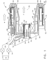
- FIG. 1 depicts an exemplary fuel nozzle 10 of a type configured to inject liquid hydrocarbon fuel into an airflow stream of a gas turbine engine combustor (not shown).
- the fuel nozzle 10 is of a "staged" type meaning it is operable to selectively inject fuel through two or more discrete stages, each stage being defined by individual fuel flowpaths within the fuel nozzle 10.
- the fuel flowrate may also be variable within each of the stages.
- the fuel nozzle 10 is connected to a fuel system 12 of a known type, operable to supply a flow of liquid fuel at varying flowrates according to operational need.
- the fuel system supplies fuel to a pilot valve 14 which coupled to a pilot fuel conduit 16, which is in turn coupled to a pilot fuel injector 18 of the fuel nozzle 10.
- the fuel system 12 also supplies fuel to a main valve 20 which is coupled to a main fuel conduit 22, which in turn supplies a main fuel injector 24.
- centerline axis 26 of the fuel nozzle 10 which is generally parallel to a centerline axis of the engine (not shown) in which the fuel nozzle 10 would be used.
- the pilot fuel injector 18 is disposed at an upstream end of the fuel nozzle 10, aligned with the centerline axis 26 and physically supported by a strut 28.
- the pilot fuel injector 18 is of a type known as "prefilming air blast", “pure air blast,” or "PAB.”
- PAB pure air blast
- Various types of pilot fuel injectors are known and may be substituted for the PAB pilot.
- the illustrated pilot fuel injector 18 includes a generally cylindrical, axially-elongated, pilot centerbody 30.
- the pilot centerbody 30 is double-walled and defines a central bore 32.
- a center swirler comprising an axially-elongated swirler centerbody 34 and a radial array of center swirl vanes 35.
- the center swirl vanes 35 are shaped and oriented to induce a swirl into air flow passing through the center swirler.
- a pilot fuel cartridge 36 is disposed with the double walls of the pilot centerbody 30.
- the pilot fuel cartridge 36 includes an axial feed passage 38 extending between the pilot fuel conduit 16 located in the strut 28, and an annular pilot feed ring 40.
- An aft end of the pilot fuel cartridge 36 communicates with an open aft end of the double walls of the pilot centerbody 30, cooperating to define a filming exit structure 42.
- An annular venturi 44 surrounds the pilot fuel injector 18. It includes, in axial sequence: a generally cylindrical upstream section 46, a throat 48 of minimum diameter, and a downstream diverging section 50.
- a radial array of outer swirl vanes 52 defining an outer air swirler extend between the pilot centerbody 30 and the venturi 44.
- the outer swirl vanes 52 physically support the pilot fuel injector 18 in cooperation with the strut 28.
- the outer swirl vanes 52 are shaped and oriented to induce a swirl into air flow passing through the outer air swirler.
- the bore of the venturi 44 defines a flowpath for a pilot air flow, generally designated "P", through the fuel nozzle 10.
- a heat shield 54 in the form of an annular, radially-extending plate may be disposed at an aft end of the diverging section 50.
- a thermal barrier coating (TBC) 56 of a known type may be applied on the surface of the heat shield 54 and/or the diverging section 50.
- the main fuel injector 24 which is annular in form surrounds the venturi 44.
- the main fuel injector 24 defines an enclosed interior volume communicating with a radial array of main fuel ports 58 through which fuel is discharged during engine operation.
- the main fuel injector 24 is supplied with fuel by the main fuel conduit 22.
- An annular outer body 60 surrounds the main fuel injector 24, venturi 44, and pilot fuel injector 18, and defines the outer extent of the fuel nozzle 10.
- the pilot fuel injector 18, venturi 44, main fuel injector 24, and outer body 60 are all coaxial with each other.
- a forward end 62 of the outer body 60 is joined to a stem housing component (not shown) when assembled.
- An aft end 64 of the outer body 60 may include an annular, radially-extending baffle 66 incorporating cooling holes 68 directed at the heat shield 54.
- the outer body 60 defines a secondary flowpath 72, in cooperation with the venturi 44 and an inner body 80 that is described below. Air passing through this secondary flowpath 72 is discharged through the cooling holes 68.
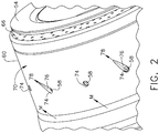
- the exterior surface 70 of the outer body 60 includes an array of recesses or openings referred to as "spray wells" 74 formed therein.
- spray wells 74 is aligned with one of the main fuel ports 58.
- the spray wells 74 may be configured to help purge fuel from the main fuel injector 24.
- some of the spray wells 74 are simple circular openings in plan view, with cylindrical walls.
- Other spray wells 74 incorporate a "scarf' comprising a ramped portion of the exterior surface 70.
- the scarf 76 When viewed in cross-section as seen in FIG. 1 , the scarf 76 has its greatest radial depth (measured relative to the exterior surface 70) at its interface with the associated main fuel port 58 and ramps or tapers outward in radial height, joining the exterior surface 70 at some distance away from the main fuel port 58.
- plan view as seen in FIG.
- the scarf 76 extends away from the main fuel port 58 along a line 78 and tapers in lateral width to a minimum width at its distal end.
- the direction that the line 78 extends defines the orientation of the scarf 76.
- the scarf may be oriented at an acute angle to the centerline axis 26.
- the scarf 76 shown in FIG. 2 is oriented in a downstream direction and thus may be referred to as a "downstream" scarf, as it is parallel to a streamline of the rotating or swirling mixer airflow M, oriented at an acute angle to the centerline axis 26, and has its distal end located downstream from the associated main fuel port 58 relative to the mixer airflow M.
- the presence or absence of the scarf 76 and orientation of the scarf 76 determines the static air pressure present at the associated main fuel port 58 during engine operation.
- the fuel nozzle 10 may include other features to perform such functions as structural support, thermal insulation, and so forth.
- an annular main ring support 78 may be connected to the strut 28 and serve as a mechanical connection between the main fuel injector 24 and stationary mounting structure such as a fuel nozzle stem (not shown).
- An annular inner body 80 surrounding the venturi 44 may serve as a radiant heat shield and also help define the boundaries of the secondary flowpath 72.
- a fluid lock 82 may be incorporated into the main fuel conduit 22 between the main valve 20 and the main fuel injector 24. As shown in FIGS. 1 and 3 , the fluid lock 82 has an upstream end 84 and a downstream end 86. An axial length "L" is defined between the upstream and downstream ends 84 and 86. The length L is selected to suit a particular application and is discussed in more detail below.
- the fluid lock 82 includes a plurality of parallel capillary channels 88 extending between the upstream and downstream ends 84 and 86.
- Each of the capillary channels 88 has a cross-sectional flow area "A1."
- the area A1 is selected considering the physical properties of the intended liquid fuel, and the material composition of the fluid lock 82, such that a capillary meniscus will remain intact across each capillary passage 88 during expected engine operating conditions (e.g. at selected temperature and acceleration conditions). This is the fundamental meaning of "capillary" as used herein.
- the capillary channels 88 would have a diameter of about 1.27mm (0.05 in) or less, corresponding to a flow area of about 1.3 mm 2 (0.002 in 2 ), where the intended liquid fuel is conventional Jet-A fuel (ASTM D1655) at temperatures ranging from ambient to 177°C (350 °F). It is noted that the capillary channels 88 may have a noncircular cross-sectional shape.
- the number of capillary channels 88 is selected to permit a desired fuel flowrate through the fluid lock 82 at appropriate fuel supply pressures. If desired, the number of capillary channels 88 may be selected such that the pressure loss across the fluid lock 82 is approximately equal to the pressure loss across an equivalent length of the main fuel conduit 22 having a cross-sectional flow area "A2," which is typically significantly greater than the flow area A1.
- the exemplary fuel nozzle 10 illustrated and described herein may be an assembly of various parts or elements. Alternatively, all or a portion of the fuel nozzle 10 or lesser subassemblies or components may be of unitary, one-piece, or monolithic configuration, and may be manufactured utilizing a rapid manufacturing process such as Direct Metal Laser Sintering (DMLS) or Direct Metal Laser Melting (DMLM).
- DMLS Direct Metal Laser Sintering
- DMLM Direct Metal Laser Melting
- both the pilot and main valves 14 and 20 are open. Liquid fuel flows under pressure from the pilot valve 14 through the pilot fuel conduit 16 into the pilot fuel cartridge 36 and is discharged into the pilot airflow P via the filming exit structure 42. The fuel subsequently atomizes and is carried downstream where it burns in the combustor (not shown).
- Liquid fuel also flows under pressure from the main valve 20 through the main fuel conduit 22, through the fluid lock 82 (if present) into the main fuel injector 24 and is discharged into the mixer airflow M via the main fuel ports 58.
- the fuel subsequently atomizes, is carried downstream, and burns in the combustor (not shown).
- pilot fuel injector 18 continues to operate and the pilot valve 14 remains open, but the main valve 20 is closed. Initially after the main valve 20 is closed, valve downstream pressure rapidly equalizes with the prevailing air pressure in the mixer airflow M and fuel flow through the main fuel ports 58 stops. If the fuel were to remain in the main fuel injector 24 it would be subject to coking as described above. At this point, the action of a purge process, such as the configuration of spray well scarfs described below, may act to positively evacuate the fuel from the fuel nozzle 10, beginning at the main fuel ports 58 and moving upstream.
- a purge process such as the configuration of spray well scarfs described below
- a volume of fuel "F” will be contained in the main fuel conduit 22 between the main valve 20 and the downstream end 86 of the fluid lock 82. More specifically, small surface tension forces of the fuel F and its adhesion to the walls of the capillary channels 88 prevent the exchange of air and fuel F at the air-liquid interface. Confining the fuel F as small fluid columns within the stationary boundaries of the capillary channels 88 reduces the mass-related forces that can be generated by the dense fuel F thereby permitting small surface tension forces to keep the fuel F in check within the confines of the capillary channels 88 of the fluid lock 82. Stated another way, a volume of fuel is positively “trapped" between the closed main valve 20 and the fluid lock 82.
- the only process by which fuel F can exit the fluid lock 82 is evaporation, beginning at the downstream end 86 and progressing upstream. If the fuel F were to clear the upstream end 84 of the fluid lock 82, there may be a tendency to drain the main fuel conduit 22, refilling the fluid lock 82 and starting a cycle of draining and filling. To avoid this situation, the length L of the fluid lock 82 may be selected based on a known or estimated evaporation rate, to ensure that evaporation does not cause the fuel-air interface to move upstream of the upstream end 84 of the fluid lock 82 for at least a selected time interval.
- the fluid lock 82 is useful in a fuel nozzle 10 whenever there is a desire to isolate or cut off liquid flow at a point downstream of a mechanical valve. By purging only the portions of the fuel nozzle 10 necessary to avoid excessive coking, a relatively small volume of fuel needs to be delivered to re-fill the fuel passages and commence discharging fuel from the main fuel ports 58 when required. This lowers combustor response time and improves engine operability as compared to a complete purge of the fuel nozzle 10 and conduit 22 as used in some prior art designs. Partial purging could be implemented using a valve (not shown) at the location of the fluid lock 82, but the fluid lock 82 has the advantage that it does not include any moving parts or sealing boundaries.
- the main fuel injector 24 communicates with an array of main fuel ports 58, each of which communicates with a single spray well 74 on the periphery of the outer body 60.
- the mixer airflow M exhibits "swirl," that is, its velocity has both axial and tangential components relative to the centerline axis 26.
- the spray wells 74 may be arranged such that alternating main fuel ports 58 are exposed to different static pressures. For example, each of the main fuel ports 58 not associated with a scarf 76 is exposed to the generally prevailing static pressure in the mixer airflow M.
- each of the main fuel ports 58 associated with a “downstream” scarf 76 is exposed to reduced static pressure relative to the prevailing static pressure in the mixer airflow M.
- lower pressure ports For purposes of description these are referred to herein as “low pressure ports.”
- one or more scarfs 76 could be oriented opposite to the orientation of the downstream scarfs 76. These would be “upstream scarfs” and the associated main fuel ports 58 would be exposed to increased static pressure relative to the prevailing static pressure in the mixer airflow M. For purposes of description these are referred to herein as “high pressure ports.”
- neutral pressure ports may alternate with low pressure ports (marked with a minus sign).
- the local static pressure differences between adjacent ports drive flow of the remaining fuel F to evacuate the main fuel injector 24.
- air enters the neutral ports (0), driving the fuel to flow tangentially in the main fuel injector 24 from the neutral ports (0) to the low-pressure ports (-), and exits the low-pressure ports (-).
- This rapidly purges the main fuel injector 24 and evacuates fuel from the portion of the main fuel conduit 22 downstream of the fluid lock 82.
- the ports and scarfs may be arranged in any configuration that will generate a pressure differential effective to drive a port-to-port purge.
- positive pressure ports could alternate with neutral pressure ports, or positive pressure ports could alternate with negative pressure ports.
- a blocking device 90 representative of either the fluid lock 82 or a functionally equivalent device is shown schematically in FIG. 4 .
- the invention described above has several advantages over the prior art. It provides a means to maintain a portion of a main circuit full of fuel from the main valve 20 downstream to the beginning of the main fuel injector 24 while still permitting the main fuel injector 24 to be purged when main fuel flow is off. This reduces the time lag for main injection associated with refilling the total volume of the main circuit after a complete purge as used in prior art designs.
- the driving purge pressure can be greatly reduced compared to a complete purge, thereby reducing the amount of hot purge air flowing thru the main fuel ports 58 and the main ring supply circuit. This reduces any added heat load imposed by purge air flow in the aft passages of the fuel nozzle 10 and provides benefit at the main fuel ports 58, leading to reduced coke formation at this location.
- the lowered heat loads associated with partial purge will also reduce thermally induced stresses in fuel passages and local structural members within the tip of the fuel nozzle 10.
- the effects of degrading material properties at temperature are reduced and overall nozzle life increases.
- main ring port-to-port purge is expected to perform the purge function in a highly consistent manner since purge circuit length is relatively short and since the main fuel injector 24 is circumferentially symmetric, meaning that the orientation of fuel nozzle installation is expected to have minimal effect on purge performance.
Claims (11)
- Appareil formant buse de carburant ayant un axe central (26), et comportant :un injecteur de carburant principal (24) comprenant un volume intérieur ;un conduit de carburant principal (22) disposé en amont de l'injecteur de carburant principal (24) et configuré pour alimenter le volume intérieur en carburant liquide ;dans lequel le volume intérieur est un volume intérieur fermé et est en outre en communication fluidique avec une pluralité d'orifices de carburant (58) configurés pour en décharger le carburant liquide ;dans lequel l'appareil formant buse comprend en outre un sas pour fluide (82) disposé entre le conduit de carburant principal (22) et l'injecteur de carburant principal (24), le sas pour fluide (82) comprenant une pluralité de canaux capillaires (88)caractérisé en ce que les canaux capillaires sont parallèles et comprennent un corps extérieur annulaire (60) entourant l'injecteur de carburant principal (24), et présentant une surface extérieure généralement cylindrique (70) comprenant un réseau de puits de pulvérisation (74) formés en son sein, chaque puits de pulvérisation (74) étant aligné avec l'un des orifices de carburant principaux (58).
- Appareil de la revendication 1, dans lequel chaque canal capillaire a une aire d'écoulement en section transversale de 0,002 pouce carré (0,00000129032 m2) ou moins.
- Appareil de la revendication 1, dans lequel une aire d'écoulement en section transversale du conduit de carburant principal (22) est supérieure à une aire d'écoulement en section transversale de l'un des canaux capillaires (88).
- Appareil selon la revendication 1, dans lequel :l'injecteur de carburant principal (24) est de forme annulaire ; etun injecteur de carburant pilote (18) est disposé coaxialement à l'intérieur de l'injecteur de carburant principal (24).
- Appareil selon la revendication 4, comprenant en outre :un venturi annulaire (44) entourant l'injecteur de carburant pilote (18) ; etun réseau radial d'aubes de tourbillonnement externes (52) reliant l'injecteur de carburant pilote (18) au venturi (44).
- Appareil selon la revendication 1, dans lequel certains des puits de pulvérisation (74) comprennent un biseau (76) comprenant une partie en rampe de la surface extérieure (70) qui est orientée selon un angle aigu par rapport à l'axe central (26).
- Appareil de la revendication 1, dans lequel les puits de pulvérisation (74) sont agencés en :un premier groupe qui ne comprend pas de biseau (76) ; etun second groupe qui incorpore chacun un biseau (76) comprenant une partie en rampe de la surface extérieure (70) qui est orientée selon un angle aigu par rapport à l'axe central (26), dans lequel les puits de pulvérisation (74) du second groupe alternent avec les puits de pulvérisation (74) du second groupe autour de la périphérie du corps extérieur (60).
- Appareil selon la revendication 7, dans lequel les puits de pulvérisation (74) du deuxième groupe sont orientés selon un angle aigu par rapport à l'axe central (26), dans une direction en aval.
- Appareil de la revendication 1, dans lequel les puits de pulvérisation (74) sont agencés de la manière suivante :un premier groupe qui incorpore chacun un biseau (76) comprenant une partie en rampe de la surface extérieure (70) qui est orientée dans une direction amont, selon un angle aigu par rapport à l'axe central (26) ; etun second groupe qui incorpore chacun un foulard (76) comprenant une partie inclinée de la surface extérieure (70) qui est orientée dans une direction en aval, selon un angle aigu par rapport à l'axe central (26), dans lequel les puits de pulvérisation (74) du second groupe alternent avec les puits de pulvérisation (74) du second groupe autour de la périphérie du corps extérieur (60).
- Appareil selon la revendication 5, dans lequel l'injecteur de carburant pilote est positionné centralement,
et dans lequel le corps extérieur annulaire (60) entoure le venturi (44) et l'injecteur de carburant pilote (18), et présente une surface extérieure généralement cylindrique (70), dans lequel certains des puits de pulvérisation (74) comprennent un biseau (76) comprenant une partie en rampe de la surface extérieure (70) qui est orientée selon un angle aigu par rapport à l'axe central (26), et comprenant en outre un dispositif de blocage (90) disposé entre le conduit de fluide principal (22) et l'injecteur de carburant principal, dans lequel le dispositif de blocage comprend le sas pour fluide. - Appareil selon la revendication précédente, comprenant en outre :un système de carburant (12) opérationnel pour fournir un flux de carburant liquide ;une vanne pilote (14) qui est couplée au système de carburant (12) et à un conduit de carburant pilote (16), le conduit de carburant pilote (16) étant couplé à l'injecteur de carburant pilote (18) ; etune vanne principale (20) qui est couplée au système de carburant (12) et au conduit de carburant principal (22).
Applications Claiming Priority (2)
| Application Number | Priority Date | Filing Date | Title |
|---|---|---|---|
| US201361909646P | 2013-11-27 | 2013-11-27 | |
| PCT/US2014/066966 WO2015122952A2 (fr) | 2013-11-27 | 2014-11-21 | Buse de ravitaillement à obturateur de fluide et appareil de purge |
Publications (2)
| Publication Number | Publication Date |
|---|---|
| EP3074697A2 EP3074697A2 (fr) | 2016-10-05 |
| EP3074697B1 true EP3074697B1 (fr) | 2019-04-10 |
Family
ID=53284487
Family Applications (1)
| Application Number | Title | Priority Date | Filing Date |
|---|---|---|---|
| EP14868715.5A Active EP3074697B1 (fr) | 2013-11-27 | 2014-11-21 | Buse de ravitaillement à obturateur de fluide et appareil de purge |
Country Status (7)
| Country | Link |
|---|---|
| US (1) | US10288293B2 (fr) |
| EP (1) | EP3074697B1 (fr) |
| JP (1) | JP6240327B2 (fr) |
| CN (1) | CN105765305B (fr) |
| BR (1) | BR112016011777A2 (fr) |
| CA (1) | CA2931246C (fr) |
| WO (1) | WO2015122952A2 (fr) |
Families Citing this family (14)
| Publication number | Priority date | Publication date | Assignee | Title |
|---|---|---|---|---|
| US20180058696A1 (en) * | 2016-08-23 | 2018-03-01 | General Electric Company | Fuel-air mixer assembly for use in a combustor of a turbine engine |
| US10739003B2 (en) * | 2016-10-03 | 2020-08-11 | United Technologies Corporation | Radial fuel shifting and biasing in an axial staged combustor for a gas turbine engine |
| CN108266274B (zh) * | 2016-12-30 | 2019-09-17 | 中国航发商用航空发动机有限责任公司 | 发动机、喷油嘴及其集油环 |
| US10775048B2 (en) * | 2017-03-15 | 2020-09-15 | General Electric Company | Fuel nozzle for a gas turbine engine |
| US10739006B2 (en) | 2017-03-15 | 2020-08-11 | General Electric Company | Fuel nozzle for a gas turbine engine |
| CN108731029B (zh) * | 2017-04-25 | 2021-10-29 | 帕克-汉尼芬公司 | 喷气燃料喷嘴 |
| WO2020123000A2 (fr) * | 2018-09-12 | 2020-06-18 | University Of Florida Research Foundation, Inc. | Injecteur de carburant pour fonctionnement de moteur à réaction hypersonique |
| CN111520750B (zh) * | 2020-03-25 | 2022-05-20 | 西北工业大学 | 新型燃烧室头部喷油结构 |
| US11639687B2 (en) * | 2020-10-22 | 2023-05-02 | Pratt & Whitney Canada Corp. | Fuel injectors and method of purging fuel injectors |
| CN114593438B (zh) * | 2020-12-02 | 2023-08-22 | 中国航发商用航空发动机有限责任公司 | 燃油喷嘴、燃烧室、燃气涡轮发动机以及防止燃油结焦的方法 |
| US20220307689A1 (en) * | 2021-03-29 | 2022-09-29 | Honeywell International Inc. | Active and passive combustion stabilization for burners for highly and rapidly varying fuel gas compositions |
| US11592177B2 (en) * | 2021-04-16 | 2023-02-28 | General Electric Company | Purging configuration for combustor mixing assembly |
| US11906165B2 (en) * | 2021-12-21 | 2024-02-20 | General Electric Company | Gas turbine nozzle having an inner air swirler passage and plural exterior fuel passages |
| US20230266012A1 (en) * | 2022-02-18 | 2023-08-24 | General Electric Company | Mixer assembly with a catalytic metal coating for a gas turbine engine |
Family Cites Families (221)
| Publication number | Priority date | Publication date | Assignee | Title |
|---|---|---|---|---|
| US1908066A (en) | 1929-08-22 | 1933-05-09 | Holzwarth Gas Turbine Co | Nozzle for gas turbines |
| GB837500A (en) | 1957-07-29 | 1960-06-15 | Cleaver Brooks Co | Oil burner purge method and system |
| US3480416A (en) | 1964-03-12 | 1969-11-25 | Sun Oil Co | Gas preparation process and apparatus |
| US3258838A (en) | 1964-08-27 | 1966-07-05 | Equipment Dev Corp | Method and apparatus for finding centers |
| US3291191A (en) | 1966-01-28 | 1966-12-13 | Sun Oil Co | Method of making a normally liquid fuel interchangeable with gas |
| GB1224521A (en) | 1968-03-27 | 1971-03-10 | Rolls Royce | Method of making an aerofoil-shaped blade or blade blank |
| FR2023239A1 (fr) | 1968-11-14 | 1970-08-07 | Mtu Muenchen Gmbh | |
| GB1281532A (en) | 1968-11-15 | 1972-07-12 | Rolls Royce | Improvements in clamping of workpieces for machining |
| US3684186A (en) | 1970-06-26 | 1972-08-15 | Ex Cell O Corp | Aerating fuel nozzle |
| US3909157A (en) | 1972-01-27 | 1975-09-30 | Chromalloy American Corp | Turbine nozzle-vane construction |
| US3837198A (en) | 1973-04-16 | 1974-09-24 | Bendix Corp | Stereoscopic gage and gaging system |
| DE2521141C3 (de) * | 1975-05-13 | 1981-01-15 | Daimler-Benz Ag, 7000 Stuttgart | Zerstäubungseinrichtung für Brennkraftmaschinen |
| DE2542719A1 (de) * | 1975-09-25 | 1977-04-07 | Daimler Benz Ag | Brennkammer |
| US4461323A (en) | 1977-08-19 | 1984-07-24 | Ngk Spark Plug Co., Ltd. | Bent honeycomb pipe assembly with central pipe |
| US4216652A (en) | 1978-06-08 | 1980-08-12 | General Motors Corporation | Integrated, replaceable combustor swirler and fuel injector |
| DE2838659C2 (de) | 1978-09-05 | 1981-07-16 | Bio-Melktechnik Swiss Hoefelmayer & Co, Niederteufen, Aargau | Schlauchanordnung für eine Viertelgemelksmaschine |
| US4327547A (en) | 1978-11-23 | 1982-05-04 | Rolls-Royce Limited | Fuel injectors |
| US4247259A (en) | 1979-04-18 | 1981-01-27 | Avco Corporation | Composite ceramic/metallic turbine blade and method of making same |
| EP0019421A3 (fr) | 1979-05-17 | 1981-01-14 | John Zink Company | Procédé pour brûler un mélange de combustible liquide et d'eau comme combustible gazeux et dispositif pour la mise en oeuvre de ce procédé |
| EP0042454A1 (fr) | 1980-06-24 | 1981-12-30 | Franz X. Wittek | Procédé de fonctionnement d'appareils à combustion et machine à combustion et dispositif de chauffage dans lequel ce procédé est mis en application |
| US4425755A (en) | 1980-09-16 | 1984-01-17 | Rolls-Royce Limited | Gas turbine dual fuel burners |
| JPS5841471U (ja) | 1981-09-12 | 1983-03-18 | 株式会社東芝 | 冷蔵庫 |
| US4584834A (en) | 1982-07-06 | 1986-04-29 | General Electric Company | Gas turbine engine carburetor |
| US4609150A (en) | 1983-07-19 | 1986-09-02 | United Technologies Corporation | Fuel nozzle for gas turbine engine |
| US4582093A (en) | 1983-12-05 | 1986-04-15 | Libbey-Owens-Ford Company | Fiber optic duct insert |
| US4674167A (en) | 1983-12-05 | 1987-06-23 | Sterling Engineered Products Inc. | Method of converting a single chambered conduit to a multi-chambered conduit |
| JPS60126521A (ja) | 1983-12-08 | 1985-07-06 | Nissan Motor Co Ltd | ガスタ−ビン用燃焼器の燃料噴射弁 |
| US4610320A (en) | 1984-09-19 | 1986-09-09 | Directional Enterprises, Inc. | Stabilizer blade |
| US4798330A (en) | 1986-02-14 | 1989-01-17 | Fuel Systems Textron Inc. | Reduced coking of fuel nozzles |
| JPS62150543U (fr) | 1986-03-18 | 1987-09-24 | ||
| US4722559A (en) | 1986-07-02 | 1988-02-02 | Heinz Bongartz | Spray hose assembly |
| US5057073A (en) | 1988-04-21 | 1991-10-15 | Vas-Cath Incorporated | Dual lumen catheter |
| US4969110A (en) | 1988-08-01 | 1990-11-06 | General Electric Company | Method of using a priori information in computerized tomography |
| GB2227190B (en) | 1989-01-24 | 1992-12-16 | Refurbished Turbine Components | Turbine blade repair |
| US5038014A (en) | 1989-02-08 | 1991-08-06 | General Electric Company | Fabrication of components by layered deposition |
| JP2798281B2 (ja) | 1989-10-31 | 1998-09-17 | 龍三 渡辺 | 粒子配列レーザー焼結方法及びその装置 |
| US5097666A (en) * | 1989-12-11 | 1992-03-24 | Sundstrand Corporation | Combustor fuel injection system |
| JPH0447479A (ja) | 1990-06-13 | 1992-02-17 | Toshiba Corp | 画像表示装置 |
| US5117637A (en) | 1990-08-02 | 1992-06-02 | General Electric Company | Combustor dome assembly |
| US5270926A (en) | 1990-12-21 | 1993-12-14 | General Electric Company | Method and apparatus for reconstructing a three-dimensional computerized tomography (CT) image of an object from incomplete cone beam projection data |
| US5460758A (en) | 1990-12-21 | 1995-10-24 | Eos Gmbh Electro Optical Systems | Method and apparatus for production of a three-dimensional object |
| US5197191A (en) | 1991-03-04 | 1993-03-30 | General Electric Company | Repair of airfoil edges |
| CA2070518C (fr) | 1991-07-01 | 2001-10-02 | Adrian Mark Ablett | Ensemble dome pour chambre de combustion |
| IT1251147B (it) | 1991-08-05 | 1995-05-04 | Ivo Panzani | Tubo multilume per separatore centrifugo particolarmente per sangue |
| JPH0586902A (ja) | 1991-09-20 | 1993-04-06 | Hitachi Ltd | 燃焼装置及びその運転方法 |
| US5321951A (en) | 1992-03-30 | 1994-06-21 | General Electric Company | Integral combustor splash plate and sleeve |
| US5309709A (en) | 1992-06-25 | 1994-05-10 | Solar Turbines Incorporated | Low emission combustion system for a gas turbine engine |
| US5321947A (en) | 1992-11-10 | 1994-06-21 | Solar Turbines Incorporated | Lean premix combustion system having reduced combustion pressure oscillation |
| US5474419A (en) | 1992-12-30 | 1995-12-12 | Reluzco; George | Flowpath assembly for a turbine diaphragm and methods of manufacture |
| US5479252A (en) | 1993-06-17 | 1995-12-26 | Ultrapointe Corporation | Laser imaging system for inspection and analysis of sub-micron particles |
| US5435884A (en) * | 1993-09-30 | 1995-07-25 | Parker-Hannifin Corporation | Spray nozzle and method of manufacturing same |
| JP3555235B2 (ja) * | 1995-04-14 | 2004-08-18 | 石川島播磨重工業株式会社 | 加圧流動層ボイラの燃料パージ方法 |
| US5715167A (en) | 1995-07-13 | 1998-02-03 | General Electric Company | Fixture for calibrated positioning of an object |
| US5761907A (en) | 1995-12-11 | 1998-06-09 | Parker-Hannifin Corporation | Thermal gradient dispersing heatshield assembly |
| US5673552A (en) | 1996-03-29 | 1997-10-07 | Solar Turbines Incorporated | Fuel injection nozzle |
| US5686676A (en) | 1996-05-07 | 1997-11-11 | Brush Wellman Inc. | Process for making improved copper/tungsten composites |
| US6032457A (en) | 1996-06-27 | 2000-03-07 | United Technologies Corporation | Fuel nozzle guide |
| US5824250A (en) | 1996-06-28 | 1998-10-20 | Alliedsignal Inc. | Gel cast molding with fugitive molds |
| US5713205A (en) | 1996-08-06 | 1998-02-03 | General Electric Co. | Air atomized discrete jet liquid fuel injector and method |
| US7194117B2 (en) | 1999-06-29 | 2007-03-20 | The Research Foundation Of State University Of New York | System and method for performing a three-dimensional virtual examination of objects, such as internal organs |
| US5916142A (en) | 1996-10-21 | 1999-06-29 | General Electric Company | Self-aligning swirler with ball joint |
| US5836163A (en) | 1996-11-13 | 1998-11-17 | Solar Turbines Incorporated | Liquid pilot fuel injection method and apparatus for a gas turbine engine dual fuel injector |
| US6144008A (en) | 1996-11-22 | 2000-11-07 | Rabinovich; Joshua E. | Rapid manufacturing system for metal, metal matrix composite materials and ceramics |
| US5794601A (en) | 1997-05-16 | 1998-08-18 | Pantone; Paul | Fuel pretreater apparatus and method |
| WO1998055800A1 (fr) | 1997-06-02 | 1998-12-10 | Solar Turbines Incorporated | Procede et dispositif d'injection d'un systeme de carburation mixte |
| US6041132A (en) | 1997-07-29 | 2000-03-21 | General Electric Company | Computed tomography inspection of composite ply structure |
| US6355086B2 (en) | 1997-08-12 | 2002-03-12 | Rolls-Royce Corporation | Method and apparatus for making components by direct laser processing |
| US6003754A (en) | 1997-10-21 | 1999-12-21 | Allison Advanced Development Co. | Airfoil for a gas turbine engine and method of manufacture |
| US5988531A (en) | 1997-11-25 | 1999-11-23 | Solar Turbines | Method of making a fuel injector |
| US5996352A (en) | 1997-12-22 | 1999-12-07 | United Technologies Corporation | Thermally decoupled swirler for a gas turbine combustor |
| US6068330A (en) | 1998-01-22 | 2000-05-30 | Honda Giken Kogyo Kabushiki Kaisha | Framework of an automobile body |
| JPH11350978A (ja) * | 1998-06-08 | 1999-12-21 | Mitsubishi Heavy Ind Ltd | 燃料ノズルパージ装置 |
| US6182436B1 (en) * | 1998-07-09 | 2001-02-06 | Pratt & Whitney Canada Corp. | Porus material torch igniter |
| US6269540B1 (en) | 1998-10-05 | 2001-08-07 | National Research Council Of Canada | Process for manufacturing or repairing turbine engine or compressor components |
| KR100291953B1 (ko) | 1999-03-15 | 2001-06-01 | 윤덕용 | 가변 용착 적층식 쾌속조형방법 및 쾌속조형장치 |
| EP1039201B1 (fr) | 1999-03-23 | 2005-11-02 | Gaimont Universal Ltd. B.V.I. | Dispositif multitubulaire extrudé |
| US6711898B2 (en) | 1999-04-01 | 2004-03-30 | Parker-Hannifin Corporation | Fuel manifold block and ring with macrolaminate layers |
| US6321541B1 (en) | 1999-04-01 | 2001-11-27 | Parker-Hannifin Corporation | Multi-circuit multi-injection point atomizer |
| US6715292B1 (en) | 1999-04-15 | 2004-04-06 | United Technologies Corporation | Coke resistant fuel injector for a low emissions combustor |
| US6227801B1 (en) | 1999-04-27 | 2001-05-08 | Pratt & Whitney Canada Corp. | Turbine engine having improved high pressure turbine cooling |
| US6405095B1 (en) | 1999-05-25 | 2002-06-11 | Nanotek Instruments, Inc. | Rapid prototyping and tooling system |
| JP3364169B2 (ja) | 1999-06-09 | 2003-01-08 | 三菱重工業株式会社 | ガスタービン及びその燃焼器 |
| US6391251B1 (en) | 1999-07-07 | 2002-05-21 | Optomec Design Company | Forming structures from CAD solid models |
| US6811744B2 (en) | 1999-07-07 | 2004-11-02 | Optomec Design Company | Forming structures from CAD solid models |
| JP2001041454A (ja) | 1999-07-27 | 2001-02-13 | Ishikawajima Harima Heavy Ind Co Ltd | 非発兼用燃料噴射ノズル |
| US6419446B1 (en) | 1999-08-05 | 2002-07-16 | United Technologies Corporation | Apparatus and method for inhibiting radial transfer of core gas flow within a core gas flow path of a gas turbine engine |
| US6283162B1 (en) | 1999-09-09 | 2001-09-04 | Boyd L. Butler | Thin boom tube exhaust pipes, method of sheet metal construction thereof, and exhaust systems which utilize such exhaust pipes for increased ground clearance on race cars |
| US6756561B2 (en) | 1999-09-30 | 2004-06-29 | National Research Council Of Canada | Laser consolidation apparatus for manufacturing precise structures |
| US6547163B1 (en) | 1999-10-01 | 2003-04-15 | Parker-Hannifin Corporation | Hybrid atomizing fuel nozzle |
| US6256995B1 (en) | 1999-11-29 | 2001-07-10 | Pratt & Whitney Canada Corp. | Simple low cost fuel nozzle support |
| US6354072B1 (en) | 1999-12-10 | 2002-03-12 | General Electric Company | Methods and apparatus for decreasing combustor emissions |
| US6460340B1 (en) | 1999-12-17 | 2002-10-08 | General Electric Company | Fuel nozzle for gas turbine engine and method of assembling |
| US6478239B2 (en) | 2000-01-25 | 2002-11-12 | John Zink Company, Llc | High efficiency fuel oil atomizer |
| US20020003001A1 (en) * | 2000-05-24 | 2002-01-10 | Weigl Bernhard H. | Surface tension valves for microfluidic applications |
| US6676892B2 (en) | 2000-06-01 | 2004-01-13 | Board Of Regents, University Texas System | Direct selective laser sintering of metals |
| US6389815B1 (en) | 2000-09-08 | 2002-05-21 | General Electric Company | Fuel nozzle assembly for reduced exhaust emissions |
| US6381964B1 (en) | 2000-09-29 | 2002-05-07 | General Electric Company | Multiple annular combustion chamber swirler having atomizing pilot |
| US6363726B1 (en) | 2000-09-29 | 2002-04-02 | General Electric Company | Mixer having multiple swirlers |
| US6367262B1 (en) | 2000-09-29 | 2002-04-09 | General Electric Company | Multiple annular swirler |
| GB0025765D0 (en) | 2000-10-20 | 2000-12-06 | Aero & Ind Technology Ltd | Fuel injector |
| US6955023B2 (en) | 2000-12-13 | 2005-10-18 | Kevin Chaite Rotheroe | Unitary metal structural member with internal reinforcement |
| DE10064267A1 (de) | 2000-12-22 | 2002-07-04 | Alstom Switzerland Ltd | Verfahren zum schnellen Herstellen von hohlen Turbinenschaufeln für die Fertigungsentwicklung und Bauteiltests |
| US20020085941A1 (en) | 2000-12-29 | 2002-07-04 | Deevi Seetharama C. | Processing of aluminides by sintering of intermetallic powders |
| US6453660B1 (en) | 2001-01-18 | 2002-09-24 | General Electric Company | Combustor mixer having plasma generating nozzle |
| US6688534B2 (en) | 2001-03-07 | 2004-02-10 | Delavan Inc | Air assist fuel nozzle |
| US6461107B1 (en) | 2001-03-27 | 2002-10-08 | General Electric Company | Turbine blade tip having thermal barrier coating-formed micro cooling channels |
| US6546732B1 (en) | 2001-04-27 | 2003-04-15 | General Electric Company | Methods and apparatus for cooling gas turbine engine combustors |
| US6442940B1 (en) | 2001-04-27 | 2002-09-03 | General Electric Company | Gas-turbine air-swirler attached to dome and combustor in single brazing operation |
| US6484489B1 (en) | 2001-05-31 | 2002-11-26 | General Electric Company | Method and apparatus for mixing fuel to decrease combustor emissions |
| US6418726B1 (en) | 2001-05-31 | 2002-07-16 | General Electric Company | Method and apparatus for controlling combustor emissions |
| US6755024B1 (en) | 2001-08-23 | 2004-06-29 | Delavan Inc. | Multiplex injector |
| CA2401060C (fr) | 2001-09-04 | 2005-04-12 | Honda Giken Kogyo Kabushiki Kaisha | Element creux de cadre de carrosserie de vehicule |
| US6523350B1 (en) | 2001-10-09 | 2003-02-25 | General Electric Company | Fuel injector fuel conduits with multiple laminated fuel strips |
| JP2003129862A (ja) | 2001-10-23 | 2003-05-08 | Toshiba Corp | タービン翼の製造方法 |
| ITMI20012780A1 (it) | 2001-12-21 | 2003-06-21 | Nuovo Pignone Spa | Dispositivo di iniezione principale di combustibile liquido per camera di combustione singola dotata di camera di pre-miscelamento di una tu |
| US6655027B2 (en) | 2002-01-15 | 2003-12-02 | General Electric Company | Methods for assembling gas turbine engine combustors |
| JP2003214300A (ja) | 2002-01-18 | 2003-07-30 | Toyota Motor Corp | インジェクタノズル製造方法 |
| US20030138679A1 (en) * | 2002-01-22 | 2003-07-24 | Ravi Prased | Fuel cartridge and reaction chamber |
| US6865889B2 (en) | 2002-02-01 | 2005-03-15 | General Electric Company | Method and apparatus to decrease combustor emissions |
| US6718770B2 (en) | 2002-06-04 | 2004-04-13 | General Electric Company | Fuel injector laminated fuel strip |
| EP1400339A1 (fr) | 2002-09-17 | 2004-03-24 | Siemens Aktiengesellschaft | Procédé pour la fabrication d'un article tridimensionnel |
| US7572524B2 (en) | 2002-09-23 | 2009-08-11 | Siemens Energy, Inc. | Method of instrumenting a component |
| US6851924B2 (en) | 2002-09-27 | 2005-02-08 | Siemens Westinghouse Power Corporation | Crack-resistance vane segment member |
| US6834505B2 (en) | 2002-10-07 | 2004-12-28 | General Electric Company | Hybrid swirler |
| US6986255B2 (en) | 2002-10-24 | 2006-01-17 | Rolls-Royce Plc | Piloted airblast lean direct fuel injector with modified air splitter |
| CA2409900C (fr) | 2002-10-29 | 2005-02-08 | Global Industries Holdings Ltd. | Tuyau d'arrosage plat et raccords pour tuyau d'arrosage plat |
| US20040086635A1 (en) | 2002-10-30 | 2004-05-06 | Grossklaus Warren Davis | Method of repairing a stationary shroud of a gas turbine engine using laser cladding |
| US6796770B2 (en) | 2002-11-06 | 2004-09-28 | Spx Corporation | Impeller and method using solid free form fabrication |
| US7007864B2 (en) | 2002-11-08 | 2006-03-07 | United Technologies Corporation | Fuel nozzle design |
| JP2004168610A (ja) | 2002-11-21 | 2004-06-17 | Toyota Motor Corp | 三次元形状焼結体の製造方法及び三次元形状焼結体 |
| US7004622B2 (en) | 2002-11-22 | 2006-02-28 | General Electric Company | Systems and methods for determining conditions of articles and methods of making such systems |
| US6915840B2 (en) | 2002-12-17 | 2005-07-12 | General Electric Company | Methods and apparatus for fabricating turbine engine airfoils |
| JP3960222B2 (ja) | 2002-12-27 | 2007-08-15 | 株式会社日立製作所 | ガスタービン燃焼器及びガスタービン燃焼器用燃料噴射ノズルとガスタービン燃焼器の燃料噴射方法 |
| US6839607B2 (en) | 2003-01-09 | 2005-01-04 | The Boeing Company | System for rapid manufacturing of replacement aerospace parts |
| US6898926B2 (en) | 2003-01-31 | 2005-05-31 | General Electric Company | Cooled purging fuel injectors |
| US6912782B2 (en) | 2003-04-09 | 2005-07-05 | Honeywell International Inc. | Forming and assembly method for multi-axial pivoting combustor liner in gas turbine engine |
| US6898938B2 (en) * | 2003-04-24 | 2005-05-31 | General Electric Company | Differential pressure induced purging fuel injector with asymmetric cyclone |
| DE10319494A1 (de) | 2003-04-30 | 2004-11-18 | Mtu Aero Engines Gmbh | Verfahren zur Reparatur und/oder Modifikation von Bauteilen einer Gasturbine |
| US7146725B2 (en) | 2003-05-06 | 2006-12-12 | Siemens Power Generation, Inc. | Repair of combustion turbine components |
| DE10326720A1 (de) | 2003-06-06 | 2004-12-23 | Rolls-Royce Deutschland Ltd & Co Kg | Brenner für eine Gasturbinenbrennkammer |
| US20050006047A1 (en) | 2003-07-10 | 2005-01-13 | General Electric Company | Investment casting method and cores and dies used therein |
| US7121095B2 (en) | 2003-08-11 | 2006-10-17 | General Electric Company | Combustor dome assembly of a gas turbine engine having improved deflector plates |
| US7062920B2 (en) | 2003-08-11 | 2006-06-20 | General Electric Company | Combustor dome assembly of a gas turbine engine having a free floating swirler |
| US6976363B2 (en) | 2003-08-11 | 2005-12-20 | General Electric Company | Combustor dome assembly of a gas turbine engine having a contoured swirler |
| US7104066B2 (en) | 2003-08-19 | 2006-09-12 | General Electric Company | Combuster swirler assembly |
| US6910864B2 (en) | 2003-09-03 | 2005-06-28 | General Electric Company | Turbine bucket airfoil cooling hole location, style and configuration |
| USD498825S1 (en) | 2003-09-08 | 2004-11-23 | Huong Huong Fu | Hose |
| JP3826196B2 (ja) | 2003-09-30 | 2006-09-27 | 独立行政法人 宇宙航空研究開発機構 | プレフィルマー式エアブラスト微粒化ノズル |
| US6951109B2 (en) | 2004-01-06 | 2005-10-04 | General Electric Company | Apparatus and methods for minimizing and/or eliminating dilution air leakage in a combustion liner assembly |
| US7363940B2 (en) | 2004-03-18 | 2008-04-29 | Parker-Hannifin Corporation | Flow-rate restrictor insert for orifice expansion device |
| EP1740304A2 (fr) | 2004-03-23 | 2007-01-10 | Velocys, Inc. | Revetements personnalises et uniformes dans un appareil a microcanaux |
| US6951227B1 (en) | 2004-04-20 | 2005-10-04 | Cheng-Wen Su | Hose with multiple holes |
| US7509735B2 (en) | 2004-04-22 | 2009-03-31 | Siemens Energy, Inc. | In-frame repairing system of gas turbine components |
| US7065972B2 (en) | 2004-05-21 | 2006-06-27 | Honeywell International, Inc. | Fuel-air mixing apparatus for reducing gas turbine combustor exhaust emissions |
| US7013649B2 (en) | 2004-05-25 | 2006-03-21 | General Electric Company | Gas turbine engine combustor mixer |
| TWI262992B (en) | 2004-06-01 | 2006-10-01 | Sunonwealth Electr Mach Ind Co | Housing structure for an axial-blowing heat-dissipating fan |
| US7207775B2 (en) | 2004-06-03 | 2007-04-24 | General Electric Company | Turbine bucket with optimized cooling circuit |
| US6993916B2 (en) | 2004-06-08 | 2006-02-07 | General Electric Company | Burner tube and method for mixing air and gas in a gas turbine engine |
| US7144221B2 (en) | 2004-07-30 | 2006-12-05 | General Electric Company | Method and apparatus for assembling gas turbine engines |
| US20060042083A1 (en) | 2004-08-27 | 2006-03-02 | Baker Martin C | Repair of turbines on wing |
| WO2006079459A1 (fr) | 2005-01-25 | 2006-08-03 | Norbert Abels | Procedes de mise en forme d'ebauches crues et articles realises par ces procedes |
| US7237730B2 (en) | 2005-03-17 | 2007-07-03 | Pratt & Whitney Canada Corp. | Modular fuel nozzle and method of making |
| EP1874674B1 (fr) * | 2005-04-14 | 2013-06-05 | Gyros Patent Ab | Bouchons liquides |
| US7779636B2 (en) | 2005-05-04 | 2010-08-24 | Delavan Inc | Lean direct injection atomizer for gas turbine engines |
| US7581396B2 (en) | 2005-07-25 | 2009-09-01 | General Electric Company | Mixer assembly for combustor of a gas turbine engine having a plurality of counter-rotating swirlers |
| US20070028595A1 (en) | 2005-07-25 | 2007-02-08 | Mongia Hukam C | High pressure gas turbine engine having reduced emissions |
| US20070028618A1 (en) | 2005-07-25 | 2007-02-08 | General Electric Company | Mixer assembly for combustor of a gas turbine engine having a main mixer with improved fuel penetration |
| US7565803B2 (en) | 2005-07-25 | 2009-07-28 | General Electric Company | Swirler arrangement for mixer assembly of a gas turbine engine combustor having shaped passages |
| US7415826B2 (en) | 2005-07-25 | 2008-08-26 | General Electric Company | Free floating mixer assembly for combustor of a gas turbine engine |
| US7464553B2 (en) | 2005-07-25 | 2008-12-16 | General Electric Company | Air-assisted fuel injector for mixer assembly of a gas turbine engine combustor |
| US7540154B2 (en) | 2005-08-11 | 2009-06-02 | Mitsubishi Heavy Industries, Ltd. | Gas turbine combustor |
| US20070071902A1 (en) | 2005-09-23 | 2007-03-29 | The Boeing Company | Rapid part fabrication employing integrated components |
| US8327538B2 (en) | 2005-10-17 | 2012-12-11 | General Electric Company | Methods to facilitate extending gas turbine engine useful life |
| US7531123B2 (en) | 2005-10-27 | 2009-05-12 | The Boeing Company | Direct manufactured self-contained parts kit |
| US7559202B2 (en) | 2005-11-15 | 2009-07-14 | Pratt & Whitney Canada Corp. | Reduced thermal stress fuel nozzle assembly |
| US7788927B2 (en) | 2005-11-30 | 2010-09-07 | General Electric Company | Turbine engine fuel nozzles and methods of assembling the same |
| US20070141375A1 (en) | 2005-12-20 | 2007-06-21 | Budinger David E | Braze cladding for direct metal laser sintered materials |
| US7429166B2 (en) * | 2005-12-20 | 2008-09-30 | General Electric Company | Methods and apparatus for gas turbine engines |
| US7434313B2 (en) | 2005-12-22 | 2008-10-14 | General Electric Company | Method for repairing a turbine engine vane assembly and repaired assembly |
| FR2896031B1 (fr) | 2006-01-09 | 2008-04-18 | Snecma Sa | Dispositif d'injection multimode pour chambre de combustion, notamment d'un turboreacteur |
| FR2896030B1 (fr) | 2006-01-09 | 2008-04-18 | Snecma Sa | Refroidissement d'un dispositif d'injection multimode pour chambre de combustion, notamment d'un turboreacteur |
| US7506510B2 (en) | 2006-01-17 | 2009-03-24 | Delavan Inc | System and method for cooling a staged airblast fuel injector |
| US8629368B2 (en) | 2006-01-30 | 2014-01-14 | Dm3D Technology, Llc | High-speed, ultra precision manufacturing station that combines direct metal deposition and EDM |
| US7358457B2 (en) | 2006-02-22 | 2008-04-15 | General Electric Company | Nozzle for laser net shape manufacturing |
| US20070207002A1 (en) | 2006-03-01 | 2007-09-06 | Roh Warren E | Cargo restraint anchor device for pick-up trucks |
| US7762073B2 (en) | 2006-03-01 | 2010-07-27 | General Electric Company | Pilot mixer for mixer assembly of a gas turbine engine combustor having a primary fuel injector and a plurality of secondary fuel injection ports |
| GB2437977A (en) | 2006-05-12 | 2007-11-14 | Siemens Ag | A swirler for use in a burner of a gas turbine engine |
| US7845549B2 (en) | 2006-05-31 | 2010-12-07 | General Electric Company | MIM braze preforms |
| US7951412B2 (en) | 2006-06-07 | 2011-05-31 | Medicinelodge Inc. | Laser based metal deposition (LBMD) of antimicrobials to implant surfaces |
| FR2903169B1 (fr) | 2006-06-29 | 2011-11-11 | Snecma | Dispositif d'injection d'un melange d'air et de carburant, chambre de combustion et turbomachine munies d'un tel dispositif |
| ATE544548T1 (de) | 2006-07-14 | 2012-02-15 | Avioprop S R L | Verfahren zum massenherstellen dreidimensionale gegenstände aus intermetallische verbindungen |
| US7926286B2 (en) | 2006-09-26 | 2011-04-19 | Pratt & Whitney Canada Corp. | Heat shield for a fuel manifold |
| US7827800B2 (en) | 2006-10-19 | 2010-11-09 | Pratt & Whitney Canada Corp. | Combustor heat shield |
| US7856826B2 (en) | 2006-11-10 | 2010-12-28 | General Electric Company | Combustor dome mixer retaining means |
| US7748221B2 (en) | 2006-11-17 | 2010-07-06 | Pratt & Whitney Canada Corp. | Combustor heat shield with variable cooling |
| US7651772B2 (en) | 2007-01-31 | 2010-01-26 | Continental Carbon Company | Core-shell carbon black pellets and method of forming same |
| US20080182017A1 (en) | 2007-01-31 | 2008-07-31 | General Electric Company | Laser net shape manufacturing and repair using a medial axis toolpath deposition method |
| US8691329B2 (en) | 2007-01-31 | 2014-04-08 | General Electric Company | Laser net shape manufacturing using an adaptive toolpath deposition method |
| US8256221B2 (en) | 2007-04-05 | 2012-09-04 | Siemens Energy, Inc. | Concentric tube support assembly |
| US20080314878A1 (en) | 2007-06-22 | 2008-12-25 | General Electric Company | Apparatus and method for controlling a machining system |
| US7665306B2 (en) | 2007-06-22 | 2010-02-23 | Honeywell International Inc. | Heat shields for use in combustors |
| JP4863085B2 (ja) | 2007-06-25 | 2012-01-25 | アイシン精機株式会社 | エンジン排ガス用浄化装置およびエンジン駆動式空気調和機 |
| US8316541B2 (en) | 2007-06-29 | 2012-11-27 | Pratt & Whitney Canada Corp. | Combustor heat shield with integrated louver and method of manufacturing the same |
| US20090032610A1 (en) * | 2007-07-30 | 2009-02-05 | Michael Scot Rosko | Anti-Drip fluid delivery device |
| US7712313B2 (en) | 2007-08-22 | 2010-05-11 | Pratt & Whitney Canada Corp. | Fuel nozzle for a gas turbine engine |
| US8196845B2 (en) | 2007-09-17 | 2012-06-12 | Delavan Inc | Flexure seal for fuel injection nozzle |
| US9188341B2 (en) | 2008-04-11 | 2015-11-17 | General Electric Company | Fuel nozzle |
| WO2009126721A2 (fr) | 2008-04-11 | 2009-10-15 | General Electric Company | Réparation d'un composant d'injecteur de carburant |
| US20090255256A1 (en) | 2008-04-11 | 2009-10-15 | General Electric Company | Method of manufacturing combustor components |
| US9046039B2 (en) * | 2008-05-06 | 2015-06-02 | Rolls-Royce Plc | Staged pilots in pure airblast injectors for gas turbine engines |
| US8104286B2 (en) | 2009-01-07 | 2012-01-31 | General Electric Company | Methods and systems to enhance flame holding in a gas turbine engine |
| US8108058B2 (en) | 2009-02-09 | 2012-01-31 | The Boeing Company | Method of analyzing composite structures |
| US20100263382A1 (en) | 2009-04-16 | 2010-10-21 | Alfred Albert Mancini | Dual orifice pilot fuel injector |
| DE102009053350B4 (de) * | 2009-11-17 | 2011-09-22 | Khs Gmbh | Füllelement |
| SG173932A1 (en) | 2010-02-25 | 2011-09-29 | United Technologies Corp | Repair of a coating on a turbine component |
| US20110259976A1 (en) | 2010-04-22 | 2011-10-27 | Matthew Tyler | Fuel injector purge tip structure |
| EP2397763A1 (fr) | 2010-06-17 | 2011-12-21 | Siemens Aktiengesellschaft | Buse d'injection, brûleur et turbine à gaz |
| US8726668B2 (en) | 2010-12-17 | 2014-05-20 | General Electric Company | Fuel atomization dual orifice fuel nozzle |
| US9310073B2 (en) * | 2011-03-10 | 2016-04-12 | Rolls-Royce Plc | Liquid swirler flow control |
| US20120227408A1 (en) | 2011-03-10 | 2012-09-13 | Delavan Inc. | Systems and methods of pressure drop control in fluid circuits through swirling flow mitigation |
| US8950188B2 (en) | 2011-09-09 | 2015-02-10 | General Electric Company | Turning guide for combustion fuel nozzle in gas turbine and method to turn fuel flow entering combustion chamber |
-
2014
- 2014-11-21 BR BR112016011777A patent/BR112016011777A2/pt not_active Application Discontinuation
- 2014-11-21 WO PCT/US2014/066966 patent/WO2015122952A2/fr active Application Filing
- 2014-11-21 EP EP14868715.5A patent/EP3074697B1/fr active Active
- 2014-11-21 CN CN201480065056.3A patent/CN105765305B/zh active Active
- 2014-11-21 JP JP2016533696A patent/JP6240327B2/ja active Active
- 2014-11-21 CA CA2931246A patent/CA2931246C/fr active Active
- 2014-11-21 US US15/039,065 patent/US10288293B2/en active Active
Non-Patent Citations (1)
| Title |
|---|
| None * |
Also Published As
| Publication number | Publication date |
|---|---|
| WO2015122952A3 (fr) | 2015-11-26 |
| WO2015122952A2 (fr) | 2015-08-20 |
| US20170159938A1 (en) | 2017-06-08 |
| CA2931246C (fr) | 2019-09-24 |
| CN105765305A (zh) | 2016-07-13 |
| BR112016011777A2 (pt) | 2017-08-08 |
| US10288293B2 (en) | 2019-05-14 |
| CN105765305B (zh) | 2018-05-08 |
| EP3074697A2 (fr) | 2016-10-05 |
| JP6240327B2 (ja) | 2017-11-29 |
| CA2931246A1 (fr) | 2015-08-20 |
| JP2017500472A (ja) | 2017-01-05 |
Similar Documents
| Publication | Publication Date | Title |
|---|---|---|
| EP3074697B1 (fr) | Buse de ravitaillement à obturateur de fluide et appareil de purge | |
| US11300295B2 (en) | Fuel nozzle structure for air assist injection | |
| US8387391B2 (en) | Aerodynamically enhanced fuel nozzle | |
| EP1445539B1 (fr) | Purge d'injecteurs de carburant par pression différentielle induite | |
| EP1445540B1 (fr) | Injecteur de carburant autopurgeur refroidi | |
| EP1471308B1 (fr) | Injecteur de combustible avec système de purge induite par pression différentielle avec cyclone asymétrique | |
| US6622488B2 (en) | Pure airblast nozzle | |
| US20170276365A1 (en) | Combustion System with Panel Fuel Injector | |
| US10184665B2 (en) | Prefilming air blast (PAB) pilot having annular splitter surrounding a pilot fuel injector | |
| EP2466206A2 (fr) | Déflecteur de résidus de conduit d'écoulement de refroidissement dans une buse de combustible | |
| EP2466207A2 (fr) | Buse de combustible à double orifice d'atomisation de carburant | |
| EP3126741B1 (fr) | Cartouche de combustible liquide de précouche | |
| EP3104081A1 (fr) | Pilote de souffle d'air de préfilmage (pab) pour chambres de combustion à faibles émissions | |
| JP3826196B2 (ja) | プレフィルマー式エアブラスト微粒化ノズル | |
| RU2531714C2 (ru) | Система горелки для установки для сжигания топлива в виде текучей среды и способ работы такой системы горелки | |
| EP2705300B1 (fr) | Lance de combustible pilote refroidi pour chambre de combustion de turbine a gaz | |
| US11592177B2 (en) | Purging configuration for combustor mixing assembly |
Legal Events
| Date | Code | Title | Description |
|---|---|---|---|
| PUAI | Public reference made under article 153(3) epc to a published international application that has entered the european phase |
Free format text: ORIGINAL CODE: 0009012 |
|
| 17P | Request for examination filed |
Effective date: 20160627 |
|
| AK | Designated contracting states |
Kind code of ref document: A2 Designated state(s): AL AT BE BG CH CY CZ DE DK EE ES FI FR GB GR HR HU IE IS IT LI LT LU LV MC MK MT NL NO PL PT RO RS SE SI SK SM TR |
|
| AX | Request for extension of the european patent |
Extension state: BA ME |
|
| DAX | Request for extension of the european patent (deleted) | ||
| STAA | Information on the status of an ep patent application or granted ep patent |
Free format text: STATUS: EXAMINATION IS IN PROGRESS |
|
| 17Q | First examination report despatched |
Effective date: 20170919 |
|
| GRAP | Despatch of communication of intention to grant a patent |
Free format text: ORIGINAL CODE: EPIDOSNIGR1 |
|
| STAA | Information on the status of an ep patent application or granted ep patent |
Free format text: STATUS: GRANT OF PATENT IS INTENDED |
|
| INTG | Intention to grant announced |
Effective date: 20181023 |
|
| GRAS | Grant fee paid |
Free format text: ORIGINAL CODE: EPIDOSNIGR3 |
|
| GRAA | (expected) grant |
Free format text: ORIGINAL CODE: 0009210 |
|
| STAA | Information on the status of an ep patent application or granted ep patent |
Free format text: STATUS: THE PATENT HAS BEEN GRANTED |
|
| AK | Designated contracting states |
Kind code of ref document: B1 Designated state(s): AL AT BE BG CH CY CZ DE DK EE ES FI FR GB GR HR HU IE IS IT LI LT LU LV MC MK MT NL NO PL PT RO RS SE SI SK SM TR |
|
| REG | Reference to a national code |
Ref country code: GB Ref legal event code: FG4D |
|
| REG | Reference to a national code |
Ref country code: CH Ref legal event code: EP Ref country code: AT Ref legal event code: REF Ref document number: 1119205 Country of ref document: AT Kind code of ref document: T Effective date: 20190415 |
|
| REG | Reference to a national code |
Ref country code: IE Ref legal event code: FG4D |
|
| REG | Reference to a national code |
Ref country code: DE Ref legal event code: R096 Ref document number: 602014044667 Country of ref document: DE |
|
| REG | Reference to a national code |
Ref country code: NL Ref legal event code: MP Effective date: 20190410 |
|
| REG | Reference to a national code |
Ref country code: LT Ref legal event code: MG4D |
|
| REG | Reference to a national code |
Ref country code: AT Ref legal event code: MK05 Ref document number: 1119205 Country of ref document: AT Kind code of ref document: T Effective date: 20190410 |
|
| PG25 | Lapsed in a contracting state [announced via postgrant information from national office to epo] |
Ref country code: NL Free format text: LAPSE BECAUSE OF FAILURE TO SUBMIT A TRANSLATION OF THE DESCRIPTION OR TO PAY THE FEE WITHIN THE PRESCRIBED TIME-LIMIT Effective date: 20190410 |
|
| PG25 | Lapsed in a contracting state [announced via postgrant information from national office to epo] |
Ref country code: FI Free format text: LAPSE BECAUSE OF FAILURE TO SUBMIT A TRANSLATION OF THE DESCRIPTION OR TO PAY THE FEE WITHIN THE PRESCRIBED TIME-LIMIT Effective date: 20190410 Ref country code: LT Free format text: LAPSE BECAUSE OF FAILURE TO SUBMIT A TRANSLATION OF THE DESCRIPTION OR TO PAY THE FEE WITHIN THE PRESCRIBED TIME-LIMIT Effective date: 20190410 Ref country code: AL Free format text: LAPSE BECAUSE OF FAILURE TO SUBMIT A TRANSLATION OF THE DESCRIPTION OR TO PAY THE FEE WITHIN THE PRESCRIBED TIME-LIMIT Effective date: 20190410 Ref country code: ES Free format text: LAPSE BECAUSE OF FAILURE TO SUBMIT A TRANSLATION OF THE DESCRIPTION OR TO PAY THE FEE WITHIN THE PRESCRIBED TIME-LIMIT Effective date: 20190410 Ref country code: SE Free format text: LAPSE BECAUSE OF FAILURE TO SUBMIT A TRANSLATION OF THE DESCRIPTION OR TO PAY THE FEE WITHIN THE PRESCRIBED TIME-LIMIT Effective date: 20190410 Ref country code: HR Free format text: LAPSE BECAUSE OF FAILURE TO SUBMIT A TRANSLATION OF THE DESCRIPTION OR TO PAY THE FEE WITHIN THE PRESCRIBED TIME-LIMIT Effective date: 20190410 Ref country code: NO Free format text: LAPSE BECAUSE OF FAILURE TO SUBMIT A TRANSLATION OF THE DESCRIPTION OR TO PAY THE FEE WITHIN THE PRESCRIBED TIME-LIMIT Effective date: 20190710 Ref country code: PT Free format text: LAPSE BECAUSE OF FAILURE TO SUBMIT A TRANSLATION OF THE DESCRIPTION OR TO PAY THE FEE WITHIN THE PRESCRIBED TIME-LIMIT Effective date: 20190910 |
|
| PG25 | Lapsed in a contracting state [announced via postgrant information from national office to epo] |
Ref country code: GR Free format text: LAPSE BECAUSE OF FAILURE TO SUBMIT A TRANSLATION OF THE DESCRIPTION OR TO PAY THE FEE WITHIN THE PRESCRIBED TIME-LIMIT Effective date: 20190711 Ref country code: PL Free format text: LAPSE BECAUSE OF FAILURE TO SUBMIT A TRANSLATION OF THE DESCRIPTION OR TO PAY THE FEE WITHIN THE PRESCRIBED TIME-LIMIT Effective date: 20190410 Ref country code: RS Free format text: LAPSE BECAUSE OF FAILURE TO SUBMIT A TRANSLATION OF THE DESCRIPTION OR TO PAY THE FEE WITHIN THE PRESCRIBED TIME-LIMIT Effective date: 20190410 Ref country code: LV Free format text: LAPSE BECAUSE OF FAILURE TO SUBMIT A TRANSLATION OF THE DESCRIPTION OR TO PAY THE FEE WITHIN THE PRESCRIBED TIME-LIMIT Effective date: 20190410 Ref country code: BG Free format text: LAPSE BECAUSE OF FAILURE TO SUBMIT A TRANSLATION OF THE DESCRIPTION OR TO PAY THE FEE WITHIN THE PRESCRIBED TIME-LIMIT Effective date: 20190710 |
|
| PG25 | Lapsed in a contracting state [announced via postgrant information from national office to epo] |
Ref country code: AT Free format text: LAPSE BECAUSE OF FAILURE TO SUBMIT A TRANSLATION OF THE DESCRIPTION OR TO PAY THE FEE WITHIN THE PRESCRIBED TIME-LIMIT Effective date: 20190410 Ref country code: IS Free format text: LAPSE BECAUSE OF FAILURE TO SUBMIT A TRANSLATION OF THE DESCRIPTION OR TO PAY THE FEE WITHIN THE PRESCRIBED TIME-LIMIT Effective date: 20190810 |
|
| REG | Reference to a national code |
Ref country code: DE Ref legal event code: R026 Ref document number: 602014044667 Country of ref document: DE |
|
| PLBI | Opposition filed |
Free format text: ORIGINAL CODE: 0009260 |
|
| PLAX | Notice of opposition and request to file observation + time limit sent |
Free format text: ORIGINAL CODE: EPIDOSNOBS2 |
|
| PG25 | Lapsed in a contracting state [announced via postgrant information from national office to epo] |
Ref country code: SK Free format text: LAPSE BECAUSE OF FAILURE TO SUBMIT A TRANSLATION OF THE DESCRIPTION OR TO PAY THE FEE WITHIN THE PRESCRIBED TIME-LIMIT Effective date: 20190410 Ref country code: EE Free format text: LAPSE BECAUSE OF FAILURE TO SUBMIT A TRANSLATION OF THE DESCRIPTION OR TO PAY THE FEE WITHIN THE PRESCRIBED TIME-LIMIT Effective date: 20190410 Ref country code: CZ Free format text: LAPSE BECAUSE OF FAILURE TO SUBMIT A TRANSLATION OF THE DESCRIPTION OR TO PAY THE FEE WITHIN THE PRESCRIBED TIME-LIMIT Effective date: 20190410 Ref country code: RO Free format text: LAPSE BECAUSE OF FAILURE TO SUBMIT A TRANSLATION OF THE DESCRIPTION OR TO PAY THE FEE WITHIN THE PRESCRIBED TIME-LIMIT Effective date: 20190410 Ref country code: DK Free format text: LAPSE BECAUSE OF FAILURE TO SUBMIT A TRANSLATION OF THE DESCRIPTION OR TO PAY THE FEE WITHIN THE PRESCRIBED TIME-LIMIT Effective date: 20190410 |
|
| 26 | Opposition filed |
Opponent name: UNITED TECHNOLOGIES CORPORATION Effective date: 20200110 |
|
| PG25 | Lapsed in a contracting state [announced via postgrant information from national office to epo] |
Ref country code: SM Free format text: LAPSE BECAUSE OF FAILURE TO SUBMIT A TRANSLATION OF THE DESCRIPTION OR TO PAY THE FEE WITHIN THE PRESCRIBED TIME-LIMIT Effective date: 20190410 Ref country code: IT Free format text: LAPSE BECAUSE OF FAILURE TO SUBMIT A TRANSLATION OF THE DESCRIPTION OR TO PAY THE FEE WITHIN THE PRESCRIBED TIME-LIMIT Effective date: 20190410 |
|
| PG25 | Lapsed in a contracting state [announced via postgrant information from national office to epo] |
Ref country code: TR Free format text: LAPSE BECAUSE OF FAILURE TO SUBMIT A TRANSLATION OF THE DESCRIPTION OR TO PAY THE FEE WITHIN THE PRESCRIBED TIME-LIMIT Effective date: 20190410 |
|
| PG25 | Lapsed in a contracting state [announced via postgrant information from national office to epo] |
Ref country code: SI Free format text: LAPSE BECAUSE OF FAILURE TO SUBMIT A TRANSLATION OF THE DESCRIPTION OR TO PAY THE FEE WITHIN THE PRESCRIBED TIME-LIMIT Effective date: 20190410 |
|
| PLBB | Reply of patent proprietor to notice(s) of opposition received |
Free format text: ORIGINAL CODE: EPIDOSNOBS3 |
|
| REG | Reference to a national code |
Ref country code: CH Ref legal event code: PL |
|
| PLAB | Opposition data, opponent's data or that of the opponent's representative modified |
Free format text: ORIGINAL CODE: 0009299OPPO |
|
| PG25 | Lapsed in a contracting state [announced via postgrant information from national office to epo] |
Ref country code: MC Free format text: LAPSE BECAUSE OF FAILURE TO SUBMIT A TRANSLATION OF THE DESCRIPTION OR TO PAY THE FEE WITHIN THE PRESCRIBED TIME-LIMIT Effective date: 20190410 Ref country code: CH Free format text: LAPSE BECAUSE OF NON-PAYMENT OF DUE FEES Effective date: 20191130 Ref country code: LU Free format text: LAPSE BECAUSE OF NON-PAYMENT OF DUE FEES Effective date: 20191121 Ref country code: LI Free format text: LAPSE BECAUSE OF NON-PAYMENT OF DUE FEES Effective date: 20191130 |
|
| R26 | Opposition filed (corrected) |
Opponent name: RAYTHEON TECHNOLOGIES CORPORATION Effective date: 20200110 |
|
| REG | Reference to a national code |
Ref country code: BE Ref legal event code: MM Effective date: 20191130 |
|
| PG25 | Lapsed in a contracting state [announced via postgrant information from national office to epo] |
Ref country code: IE Free format text: LAPSE BECAUSE OF NON-PAYMENT OF DUE FEES Effective date: 20191121 |
|
| PG25 | Lapsed in a contracting state [announced via postgrant information from national office to epo] |
Ref country code: BE Free format text: LAPSE BECAUSE OF NON-PAYMENT OF DUE FEES Effective date: 20191130 |
|
| PG25 | Lapsed in a contracting state [announced via postgrant information from national office to epo] |
Ref country code: CY Free format text: LAPSE BECAUSE OF FAILURE TO SUBMIT A TRANSLATION OF THE DESCRIPTION OR TO PAY THE FEE WITHIN THE PRESCRIBED TIME-LIMIT Effective date: 20190410 |
|
| REG | Reference to a national code |
Ref country code: DE Ref legal event code: R100 Ref document number: 602014044667 Country of ref document: DE |
|
| PG25 | Lapsed in a contracting state [announced via postgrant information from national office to epo] |
Ref country code: HU Free format text: LAPSE BECAUSE OF FAILURE TO SUBMIT A TRANSLATION OF THE DESCRIPTION OR TO PAY THE FEE WITHIN THE PRESCRIBED TIME-LIMIT; INVALID AB INITIO Effective date: 20141121 Ref country code: MT Free format text: LAPSE BECAUSE OF FAILURE TO SUBMIT A TRANSLATION OF THE DESCRIPTION OR TO PAY THE FEE WITHIN THE PRESCRIBED TIME-LIMIT Effective date: 20190410 |
|
| PLCK | Communication despatched that opposition was rejected |
Free format text: ORIGINAL CODE: EPIDOSNREJ1 |
|
| PLBN | Opposition rejected |
Free format text: ORIGINAL CODE: 0009273 |
|
| STAA | Information on the status of an ep patent application or granted ep patent |
Free format text: STATUS: OPPOSITION REJECTED |
|
| 27O | Opposition rejected |
Effective date: 20210611 |
|
| PG25 | Lapsed in a contracting state [announced via postgrant information from national office to epo] |
Ref country code: MK Free format text: LAPSE BECAUSE OF FAILURE TO SUBMIT A TRANSLATION OF THE DESCRIPTION OR TO PAY THE FEE WITHIN THE PRESCRIBED TIME-LIMIT Effective date: 20190410 |
|
| P01 | Opt-out of the competence of the unified patent court (upc) registered |
Effective date: 20230414 |
|
| PGFP | Annual fee paid to national office [announced via postgrant information from national office to epo] |
Ref country code: GB Payment date: 20231019 Year of fee payment: 10 |
|
| PGFP | Annual fee paid to national office [announced via postgrant information from national office to epo] |
Ref country code: FR Payment date: 20231019 Year of fee payment: 10 Ref country code: DE Payment date: 20231019 Year of fee payment: 10 |