EP1400339A1 - Procédé pour la fabrication d'un article tridimensionnel - Google Patents
Procédé pour la fabrication d'un article tridimensionnel Download PDFInfo
- Publication number
- EP1400339A1 EP1400339A1 EP02020817A EP02020817A EP1400339A1 EP 1400339 A1 EP1400339 A1 EP 1400339A1 EP 02020817 A EP02020817 A EP 02020817A EP 02020817 A EP02020817 A EP 02020817A EP 1400339 A1 EP1400339 A1 EP 1400339A1
- Authority
- EP
- European Patent Office
- Prior art keywords
- subsets
- shaped body
- feed
- dimensional shaped
- starting
- Prior art date
- Legal status (The legal status is an assumption and is not a legal conclusion. Google has not performed a legal analysis and makes no representation as to the accuracy of the status listed.)
- Withdrawn
Links
- LSHUIGIYBNJHEQ-UHFFFAOYSA-N C(CC1CCCC1)C1CCC1 Chemical compound C(CC1CCCC1)C1CCC1 LSHUIGIYBNJHEQ-UHFFFAOYSA-N 0.000 description 1
Images

Classifications
-
- C—CHEMISTRY; METALLURGY
- C30—CRYSTAL GROWTH
- C30B—SINGLE-CRYSTAL GROWTH; UNIDIRECTIONAL SOLIDIFICATION OF EUTECTIC MATERIAL OR UNIDIRECTIONAL DEMIXING OF EUTECTOID MATERIAL; REFINING BY ZONE-MELTING OF MATERIAL; PRODUCTION OF A HOMOGENEOUS POLYCRYSTALLINE MATERIAL WITH DEFINED STRUCTURE; SINGLE CRYSTALS OR HOMOGENEOUS POLYCRYSTALLINE MATERIAL WITH DEFINED STRUCTURE; AFTER-TREATMENT OF SINGLE CRYSTALS OR A HOMOGENEOUS POLYCRYSTALLINE MATERIAL WITH DEFINED STRUCTURE; APPARATUS THEREFOR
- C30B29/00—Single crystals or homogeneous polycrystalline material with defined structure characterised by the material or by their shape
- C30B29/60—Single crystals or homogeneous polycrystalline material with defined structure characterised by the material or by their shape characterised by shape
-
- B—PERFORMING OPERATIONS; TRANSPORTING
- B22—CASTING; POWDER METALLURGY
- B22F—WORKING METALLIC POWDER; MANUFACTURE OF ARTICLES FROM METALLIC POWDER; MAKING METALLIC POWDER; APPARATUS OR DEVICES SPECIALLY ADAPTED FOR METALLIC POWDER
- B22F10/00—Additive manufacturing of workpieces or articles from metallic powder
- B22F10/20—Direct sintering or melting
- B22F10/28—Powder bed fusion, e.g. selective laser melting [SLM] or electron beam melting [EBM]
-
- B—PERFORMING OPERATIONS; TRANSPORTING
- B22—CASTING; POWDER METALLURGY
- B22F—WORKING METALLIC POWDER; MANUFACTURE OF ARTICLES FROM METALLIC POWDER; MAKING METALLIC POWDER; APPARATUS OR DEVICES SPECIALLY ADAPTED FOR METALLIC POWDER
- B22F12/00—Apparatus or devices specially adapted for additive manufacturing; Auxiliary means for additive manufacturing; Combinations of additive manufacturing apparatus or devices with other processing apparatus or devices
- B22F12/50—Means for feeding of material, e.g. heads
- B22F12/55—Two or more means for feeding material
-
- B—PERFORMING OPERATIONS; TRANSPORTING
- B23—MACHINE TOOLS; METAL-WORKING NOT OTHERWISE PROVIDED FOR
- B23P—METAL-WORKING NOT OTHERWISE PROVIDED FOR; COMBINED OPERATIONS; UNIVERSAL MACHINE TOOLS
- B23P15/00—Making specific metal objects by operations not covered by a single other subclass or a group in this subclass
- B23P15/04—Making specific metal objects by operations not covered by a single other subclass or a group in this subclass turbine or like blades from several pieces
-
- B—PERFORMING OPERATIONS; TRANSPORTING
- B29—WORKING OF PLASTICS; WORKING OF SUBSTANCES IN A PLASTIC STATE IN GENERAL
- B29C—SHAPING OR JOINING OF PLASTICS; SHAPING OF MATERIAL IN A PLASTIC STATE, NOT OTHERWISE PROVIDED FOR; AFTER-TREATMENT OF THE SHAPED PRODUCTS, e.g. REPAIRING
- B29C64/00—Additive manufacturing, i.e. manufacturing of three-dimensional [3D] objects by additive deposition, additive agglomeration or additive layering, e.g. by 3D printing, stereolithography or selective laser sintering
- B29C64/10—Processes of additive manufacturing
- B29C64/141—Processes of additive manufacturing using only solid materials
- B29C64/153—Processes of additive manufacturing using only solid materials using layers of powder being selectively joined, e.g. by selective laser sintering or melting
-
- C—CHEMISTRY; METALLURGY
- C30—CRYSTAL GROWTH
- C30B—SINGLE-CRYSTAL GROWTH; UNIDIRECTIONAL SOLIDIFICATION OF EUTECTIC MATERIAL OR UNIDIRECTIONAL DEMIXING OF EUTECTOID MATERIAL; REFINING BY ZONE-MELTING OF MATERIAL; PRODUCTION OF A HOMOGENEOUS POLYCRYSTALLINE MATERIAL WITH DEFINED STRUCTURE; SINGLE CRYSTALS OR HOMOGENEOUS POLYCRYSTALLINE MATERIAL WITH DEFINED STRUCTURE; AFTER-TREATMENT OF SINGLE CRYSTALS OR A HOMOGENEOUS POLYCRYSTALLINE MATERIAL WITH DEFINED STRUCTURE; APPARATUS THEREFOR
- C30B11/00—Single-crystal growth by normal freezing or freezing under temperature gradient, e.g. Bridgman-Stockbarger method
-
- B—PERFORMING OPERATIONS; TRANSPORTING
- B22—CASTING; POWDER METALLURGY
- B22F—WORKING METALLIC POWDER; MANUFACTURE OF ARTICLES FROM METALLIC POWDER; MAKING METALLIC POWDER; APPARATUS OR DEVICES SPECIALLY ADAPTED FOR METALLIC POWDER
- B22F10/00—Additive manufacturing of workpieces or articles from metallic powder
- B22F10/30—Process control
- B22F10/38—Process control to achieve specific product aspects, e.g. surface smoothness, density, porosity or hollow structures
-
- B—PERFORMING OPERATIONS; TRANSPORTING
- B22—CASTING; POWDER METALLURGY
- B22F—WORKING METALLIC POWDER; MANUFACTURE OF ARTICLES FROM METALLIC POWDER; MAKING METALLIC POWDER; APPARATUS OR DEVICES SPECIALLY ADAPTED FOR METALLIC POWDER
- B22F12/00—Apparatus or devices specially adapted for additive manufacturing; Auxiliary means for additive manufacturing; Combinations of additive manufacturing apparatus or devices with other processing apparatus or devices
- B22F12/10—Auxiliary heating means
- B22F12/13—Auxiliary heating means to preheat the material
-
- B—PERFORMING OPERATIONS; TRANSPORTING
- B22—CASTING; POWDER METALLURGY
- B22F—WORKING METALLIC POWDER; MANUFACTURE OF ARTICLES FROM METALLIC POWDER; MAKING METALLIC POWDER; APPARATUS OR DEVICES SPECIALLY ADAPTED FOR METALLIC POWDER
- B22F12/00—Apparatus or devices specially adapted for additive manufacturing; Auxiliary means for additive manufacturing; Combinations of additive manufacturing apparatus or devices with other processing apparatus or devices
- B22F12/10—Auxiliary heating means
- B22F12/17—Auxiliary heating means to heat the build chamber or platform
-
- B—PERFORMING OPERATIONS; TRANSPORTING
- B22—CASTING; POWDER METALLURGY
- B22F—WORKING METALLIC POWDER; MANUFACTURE OF ARTICLES FROM METALLIC POWDER; MAKING METALLIC POWDER; APPARATUS OR DEVICES SPECIALLY ADAPTED FOR METALLIC POWDER
- B22F2998/00—Supplementary information concerning processes or compositions relating to powder metallurgy
-
- B—PERFORMING OPERATIONS; TRANSPORTING
- B22—CASTING; POWDER METALLURGY
- B22F—WORKING METALLIC POWDER; MANUFACTURE OF ARTICLES FROM METALLIC POWDER; MAKING METALLIC POWDER; APPARATUS OR DEVICES SPECIALLY ADAPTED FOR METALLIC POWDER
- B22F2999/00—Aspects linked to processes or compositions used in powder metallurgy
-
- B—PERFORMING OPERATIONS; TRANSPORTING
- B23—MACHINE TOOLS; METAL-WORKING NOT OTHERWISE PROVIDED FOR
- B23P—METAL-WORKING NOT OTHERWISE PROVIDED FOR; COMBINED OPERATIONS; UNIVERSAL MACHINE TOOLS
- B23P2700/00—Indexing scheme relating to the articles being treated, e.g. manufactured, repaired, assembled, connected or other operations covered in the subgroups
- B23P2700/12—Laminated parts
-
- Y—GENERAL TAGGING OF NEW TECHNOLOGICAL DEVELOPMENTS; GENERAL TAGGING OF CROSS-SECTIONAL TECHNOLOGIES SPANNING OVER SEVERAL SECTIONS OF THE IPC; TECHNICAL SUBJECTS COVERED BY FORMER USPC CROSS-REFERENCE ART COLLECTIONS [XRACs] AND DIGESTS
- Y02—TECHNOLOGIES OR APPLICATIONS FOR MITIGATION OR ADAPTATION AGAINST CLIMATE CHANGE
- Y02P—CLIMATE CHANGE MITIGATION TECHNOLOGIES IN THE PRODUCTION OR PROCESSING OF GOODS
- Y02P10/00—Technologies related to metal processing
- Y02P10/25—Process efficiency
Definitions
- the invention relates to a method for producing a three-dimensional shaped body.
- DE 199 03 436 C2 describes a process for the production three-dimensional shaped body known, in which a first Envelope is built up and then with a second Material is at least partially filled.
- the envelope is an essential requirement for the procedure.
- EP 892 090 A1 shows a method for repairing a three-dimensional body, in which only near the surface Area a layer is applied.
- the object is achieved by a method according to claim 1. Different consistencies become at least two layered subsets of at least one starting material connected to a three-dimensional shaped body.
- Figure 1 shows an exemplary device 1 to the perform the method according to the invention.
- a starting plate 4 for example, is arranged within an optionally available heater 34, on which a first layered subset 7 of at least one first starting material rests.
- the subset 7 can be shifted relative to the heater 34 in a direction 25 of the three-dimensional shaped body or the heater 34 is shifted relative to the subset 7 or the shaped body to be assembled.
- subset 7 is, for example, a layered powder compact, a powder bed 52 to be built up in layers (FIG. 6) or a sheet metal or a metal foil (both in layer form).
- At least one laser 16 the desired geometry for the to produce three-dimensional moldings, if this is not yet available.
- the first layer-shaped subset 7 is compressed, for example. This is necessary for powder compacts and powder fillings, not necessarily for sheet metal or metal foils. This can be done by known thermal compression processes (sintering) or with laser beams 13 or electron beams that originate from the laser 16 and act on the subset 7 (laser sintering). The laser beams 13 can completely or partially cover the first subset 7 and, if necessary, even melt the material of the first subset 7.
- the laser 16 and / or its laser beams 13 can change their position in relation to the first subset 7 in all spatial directions.
- a CAD model of the three-dimensional shaped body is stored in a control unit 37, so that the laser (s) 16 / laser beams 13 are controlled in such a way that the desired three-dimensional shaped body with its outer and outer surfaces is formed from the first partial quantity 7 and further partial quantities 10 (FIG. 2) inner dimensions according to the CAD model.
- the laser 16 can cause the subset 7 to be compressed and, if necessary, the first subset 7 to be shaped. Shaping does not have to take place, for example, if the shape of the powder compact already corresponds to the corresponding part of the three-dimensional shaped body, for example after its shrinkage after compression. As many layer-shaped subsets 10 are required to complete the shaped body as it corresponds to the height of the shaped body in the direction of assembly 25.
- Figure 2 shows a further process step of inventive method.
- a second layer-shaped partial quantity 10 is arranged on the first partial quantity 7.
- the second subset 10 consists, but not necessarily, of a second starting material, for example, in order to generate a material gradient in the molded body, for example.
- the second subset 10 is also compressed, for example, in particular by exposure to laser beams 13.
- Laser 16 may also effect shaping of second subset 10.
- the layer-like subsets 7, 10 are connected to one another by the thermal treatment, for example by laser treatment, for example by sintering or fusion.
- the three-dimensional shaped body to be produced from the at least two subsets 7, 10 has a directionally solidified structure, ie a single-crystalline structure (SX) or only grain boundaries (DS) along one direction (assembly direction 25).
- SX single-crystalline structure
- DS grain boundaries
- the starting plate 4 has a desired crystalline structure of the three-dimensional shaped body to be produced.
- the first step the first partial amount 7 is melted and cooled in a controlled manner, the desired crystalline structure being produced.
- the second subset 10 is placed and melted, as a result of which it connects to the first subset 7.
- the first subset 7 is melted slightly on the surface.
- the solidification front with the desired crystalline structure migrates from the first subset 7 into the second subset 10 by suitable guidance, for example of the heater 34 and / or heating by the laser 16.
- This process can be repeated any number of times.
- EP 892 090 A1 which is expressly intended to be part of this disclosure.
- the dimensions of the subsets 7, 10 therefore do not have to correspond to the desired three-dimensional shaped body.
- An outer shape or shell, such as. B. is necessary when casting, is not necessary here.
- the connection of the layered subsets is repeated until the molded body has been formed.
- the molded body is created entirely from individual layers, for example 0.1 mm to 1 cm thick.
- the shaped body perpendicular to a plane in which the layer-shaped subsets 7, 10 extend is longer than the extent of the shaped body in this plane, as is the case, for example, with a turbine blade.
- a turbine blade is manufactured, for example, layer by layer starting with the blade root up to the blade tip.
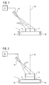
- FIG. 3 shows a cross section of a subset 7, 10 perpendicular to the assembly direction 25.
- the subset 7 is, for example, a powder compact, which has a cavity 19 inside, which is enclosed by a wall 22.
- Such hollow components are used in particular as turbine blades (three-dimensional component) which are cooled in the interior 19 and are enclosed by an outer wall 22.
- the subset 7, 10 can also be a powder compact which has no cavity 19.
- the laser beams 13 By suitable guiding of the laser beams 13, only the areas of the partial quantity 7, 10 are compressed or melted and left to solidify, which correspond to the wall 22 of the component to be produced (three-dimensional shaped body).
- the pressed powder in the middle remains undensified and loose and can be easily removed after the three-dimensional shaped body has been produced.
- Metal sheets or foils can also be used, which are given their outer and inner shape by the laser 16 and are then melted.
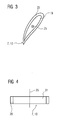
- FIG. 4 shows further subsets 7, 10.
- the subset 7, 10 is, for example, a powder compact and its composition can have a gradient or a layer structure in the direction of construction 25 or in the plane perpendicular to the direction of construction 25. The latter is the case in Figure 4.
- the subset 7, 10 consists, for example, of a material, for example a powder for a nickel or cobalt-based superalloy.
- the inner region 31 is encased by a layer 28 which has a different material composition than that of the inner region 31.
- This is, for example, a powder for an MCrAlY layer, where M stands for element from the group iron, cobalt or nickel.
- FIG. 5 shows an example of a first subset 7, a second subset 10 in which fibers 40 are arranged and a further subset 55.
- the fibers 40 can be directional or randomly jumbled. Fiber mats can also be used.
- the fibers 40 may have been pressed into powder compacts 7, 10 or may already be present in the metal sheets.
- the next layered subset 55 may, but need not, have any fibers either because, for example, no mechanical reinforcement is necessary there.
- the three-dimensional shaped body thus has a material gradient, as is also present in principle in FIG. 4.
- FIG. 6 shows a further device 1 for carrying out the method according to the invention.
- the laser 16 strikes a powder bed 52 with its laser beams 13, which represents a further consistency of the at least one starting material.
- the method is started with a certain amount of powder of a first starting material, which represents the powder bed 52 (first subset 7).
- first and / or a second material feed 46, 49 further material in the form of powder (second subset 10) is continuously or discontinuously added to the powder bed 52, so that the powder bed 52 increases in layers in the direction of construction 25.
- the composition of the supplied material can change by adding a second starting material to the first starting material in order to obtain an even distribution of a second phase (material supply for the second starting material is constant in terms of time and place, based on the powder bed 52) or by a material gradient in the subset to generate (material supply for second starting material locally, based on the powder bed 52, and possibly different in time).
- the material feeds 46, 49 can be moved locally in all directions (x, y, z).
- the first material feed 46 feeds, for example, a matrix material and the second material feed 49 can feed fibers, second phases or other components, for example.
- the laser beams 13 are used to compact only the areas of the powder bed 52 that are specified in a specified CAD model. After completion of the three-dimensional shaped body, the compressed material is removed from the loose powder filling 52. Fibers 40 or other second phases can also be present in the powder filling 52.
- first and second material feeds 46, 49 can be controlled by temporally and / or locally controlling the first and second material feeds 46, 49.
- the matrix material of the component to be manufactured is fed through the first material feed 46.
- the second material feed 49 can locally feed fibers, second phases or other constituents in different concentrations in order to generate the gradient.
- the material feeds 46, 49 can be moved in the lateral plane and in the assembly direction 25, so that a different material composition can take place in an inner and an outer area, for example by the first material feed 46 in the inner area 31 (FIG. 4) being a material feeds a superalloy and the second material feed 49 in the outer area 28 feeds, for example, the same material enriched with, for example, aluminum, chromium or MCrAlY (FIG. 4).
- a gradient in the composition can exist in the direction of construction 25 and in the plane perpendicular thereto.
- a turbine blade can have a different composition on its convex side than on the concave side. This type of gradient cannot be achieved with a casting process.
- a material gradient can be generated by changing the composition of the material over time, which is supplied via the material feeds 46, 49. If the material feed 46, 49 with respect to the three-dimensional shaped body to be produced is oriented such that the material there should have a different composition, the composition in the material feeds 46, 49 is changed at the appropriate point in time. This can be repeated from time to time.
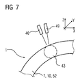
- the explanations for the production of gradients or of second phases in the shaped body apply to the different methods described in this application (FIGS. 2, 6 and 7)
- Figure 7 shows a further device 1 to a perform the method according to the invention.
- a three-dimensional shaped body can also be produced without powder compacts 7, 10, powder fillings 52.
- the partial quantities 7, 70 are supplied in the form of powder via the first and / or second material feed 46, 49 on the starting plate 4 only to those locations where the geometry of the three-dimensional shaped body to be produced requires.
- the supplied material is connected to one another and compressed by means of electron beams or laser beams 13 with a laser focal spot 43, for example.
- the material feeds 46, 49 and the laser 16 or its laser beams 13 can be guided in three-dimensional space according to the desired geometry of the molded body.
Priority Applications (6)
| Application Number | Priority Date | Filing Date | Title |
|---|---|---|---|
| EP02020817A EP1400339A1 (fr) | 2002-09-17 | 2002-09-17 | Procédé pour la fabrication d'un article tridimensionnel |
| ES03798113T ES2266909T3 (es) | 2002-09-17 | 2003-08-20 | Procedimiento para producir un cuerpo de moldeo tridimensional. |
| PCT/EP2003/009236 WO2004028786A1 (fr) | 2002-09-17 | 2003-08-20 | Procede pour realiser un element moule tridimensionnel |
| DE50304075T DE50304075D1 (de) | 2002-09-17 | 2003-08-20 | Verfahren zum herstellen eines dreidimensionalen formkörpers |
| US10/527,429 US7455740B2 (en) | 2002-09-17 | 2003-08-20 | Method for producing a three-dimensional moulded body |
| EP03798113A EP1539465B1 (fr) | 2002-09-17 | 2003-08-20 | Procede pour realiser un element moule tridimensionnel |
Applications Claiming Priority (1)
| Application Number | Priority Date | Filing Date | Title |
|---|---|---|---|
| EP02020817A EP1400339A1 (fr) | 2002-09-17 | 2002-09-17 | Procédé pour la fabrication d'un article tridimensionnel |
Publications (1)
| Publication Number | Publication Date |
|---|---|
| EP1400339A1 true EP1400339A1 (fr) | 2004-03-24 |
Family
ID=31896865
Family Applications (2)
| Application Number | Title | Priority Date | Filing Date |
|---|---|---|---|
| EP02020817A Withdrawn EP1400339A1 (fr) | 2002-09-17 | 2002-09-17 | Procédé pour la fabrication d'un article tridimensionnel |
| EP03798113A Expired - Lifetime EP1539465B1 (fr) | 2002-09-17 | 2003-08-20 | Procede pour realiser un element moule tridimensionnel |
Family Applications After (1)
| Application Number | Title | Priority Date | Filing Date |
|---|---|---|---|
| EP03798113A Expired - Lifetime EP1539465B1 (fr) | 2002-09-17 | 2003-08-20 | Procede pour realiser un element moule tridimensionnel |
Country Status (5)
| Country | Link |
|---|---|
| US (1) | US7455740B2 (fr) |
| EP (2) | EP1400339A1 (fr) |
| DE (1) | DE50304075D1 (fr) |
| ES (1) | ES2266909T3 (fr) |
| WO (1) | WO2004028786A1 (fr) |
Cited By (11)
| Publication number | Priority date | Publication date | Assignee | Title |
|---|---|---|---|---|
| WO2008034413A1 (fr) | 2006-09-21 | 2008-03-27 | Mtu Aero Engines Gmbh | Procédé de réparation |
| WO2008046386A1 (fr) * | 2006-10-18 | 2008-04-24 | Mtu Aero Engines Gmbh | Procédé de fabrication d'un élément de turbine à gaz |
| WO2008046388A1 (fr) * | 2006-10-18 | 2008-04-24 | Mtu Aero Engines Gmbh | Rotor de turbine haute pression et son procédé de réalisation |
| DE102007033715A1 (de) * | 2007-07-19 | 2009-01-22 | Siemens Ag | Verfahren zum Aufbringen einer aus mehreren Materialien bestehenden Produktschicht auf einen Formkörper |
| DE102008056336A1 (de) * | 2008-11-07 | 2010-05-12 | Mtu Aero Engines Gmbh | Reparaturverfahren |
| WO2010057469A1 (fr) * | 2008-11-22 | 2010-05-27 | Mtu Aero Engines Gmbh | Procédé pour fabriquer ou réparer des éléments de turbine à gaz |
| DE102009051479A1 (de) * | 2009-10-30 | 2011-05-05 | Mtu Aero Engines Gmbh | Verfahren und Vorrichtung zur Herstellung eines Bauteils einer Strömungsmaschine |
| WO2013075683A1 (fr) * | 2011-11-22 | 2013-05-30 | Mtu Aero Engines Gmbh | Procédé et dispositif de production additive d'un élément structural au moyen d'un faisceau laser ; élément structural correspondant |
| ITCO20120058A1 (it) * | 2012-12-13 | 2014-06-14 | Nuovo Pignone Srl | Metodi per produrre pale divise di turbomacchine mediante produzione additiva, pale di turbomacchina e turbomacchine |
| EP2815824A1 (fr) * | 2013-06-21 | 2014-12-24 | Siemens Aktiengesellschaft | Procédé de fabrication d'un composant |
| FR3046559A1 (fr) * | 2016-01-12 | 2017-07-14 | Inetyx | Procede et installation de fabrication d'un objet tridimensionnel |
Families Citing this family (38)
| Publication number | Priority date | Publication date | Assignee | Title |
|---|---|---|---|---|
| US20070163114A1 (en) * | 2006-01-13 | 2007-07-19 | General Electric Company | Methods for fabricating components |
| JP4744480B2 (ja) * | 2007-05-30 | 2011-08-10 | 株式会社日立製作所 | 仮想計算機システム |
| US8029642B2 (en) | 2007-07-27 | 2011-10-04 | The Boeing Company | Tape removal apparatus and process |
| US8345269B2 (en) | 2007-09-22 | 2013-01-01 | The Boeing Company | Method and apparatus for measuring the width of composite tape |
| US7922856B2 (en) * | 2008-01-02 | 2011-04-12 | The Boeing Company | Graphite tape supply and backing paper take-up apparatus |
| US8557074B2 (en) | 2008-02-27 | 2013-10-15 | The Boeing Company | Reduced complexity automatic fiber placement apparatus and method |
| US8986482B2 (en) | 2008-07-08 | 2015-03-24 | The Boeing Company | Method and apparatus for producing composite structures |
| EP2226149A1 (fr) * | 2009-03-04 | 2010-09-08 | Siemens Aktiengesellschaft | Procédé de soudure en deux étapes |
| US8308101B2 (en) | 2009-03-09 | 2012-11-13 | The Boeing Company | Simplified fiber tensioning for automated fiber placement machines |
| US8454788B2 (en) | 2009-03-13 | 2013-06-04 | The Boeing Company | Method and apparatus for placing short courses of composite tape |
| DE102009048665A1 (de) * | 2009-09-28 | 2011-03-31 | Siemens Aktiengesellschaft | Turbinenschaufel und Verfahren zu deren Herstellung |
| DE102010011059A1 (de) | 2010-03-11 | 2011-09-15 | Global Beam Technologies Ag | Verfahren und Vorrichtung zur Herstellung eines Bauteils |
| DE102010034337A1 (de) * | 2010-08-14 | 2012-02-16 | Mtu Aero Engines Gmbh | Verfahren zum Verbinden einer Turbinenschaufel mit einer Turbinenscheibe oder einem Turbinenring |
| US8691333B2 (en) * | 2011-06-28 | 2014-04-08 | Honeywell International Inc. | Methods for manufacturing engine components with structural bridge devices |
| DE102011080187A1 (de) * | 2011-08-01 | 2013-02-07 | Siemens Aktiengesellschaft | Verfahren zum Erzeugen einer Schaufel für eine Strömungskraftmaschine und Schaufel für eine Strömungskraftmaschine |
| DE102011081112A1 (de) | 2011-08-17 | 2013-02-21 | Rolls-Royce Deutschland Ltd & Co Kg | Verfahren zur Herstellung eines Bauteils für hohe thermische Belastungen, ein Bauteil herstellbar mit dem Verfahren und ein Flugzeugtriebwerk mit dem Bauteil |
| US9266170B2 (en) | 2012-01-27 | 2016-02-23 | Honeywell International Inc. | Multi-material turbine components |
| DE102012212587A1 (de) * | 2012-07-18 | 2014-01-23 | Eos Gmbh Electro Optical Systems | Vorrichtung und Verfahren zum schichtweisen Herstellen eines dreidimensionalen Objekts |
| EP2696028A1 (fr) * | 2012-08-06 | 2014-02-12 | Siemens Aktiengesellschaft | Composant de turbomachine pour courant de gaz chauds d'une turbine à gaz |
| US20140099476A1 (en) * | 2012-10-08 | 2014-04-10 | Ramesh Subramanian | Additive manufacture of turbine component with multiple materials |
| US9770781B2 (en) * | 2013-01-31 | 2017-09-26 | Siemens Energy, Inc. | Material processing through optically transmissive slag |
| US20150030871A1 (en) * | 2013-07-26 | 2015-01-29 | Gerald J. Bruck | Functionally graded thermal barrier coating system |
| EP2839905A1 (fr) * | 2013-08-22 | 2015-02-25 | Astrium GmbH | Fabrication de composants à partir de pièces fabriquées à partir de différents matériaux, notamment de composants de transport spatial tels que des chambres de combustion pour propulseurs |
| EP2843192B1 (fr) * | 2013-08-28 | 2021-03-24 | Safran Aero Boosters SA | Aube composite réalisée par fabrication additive et procédé de fabrication associé |
| CN105705278B (zh) | 2013-11-14 | 2018-06-22 | 通用电气公司 | 单晶合金构件的分层制造 |
| BR112016011777A2 (pt) | 2013-11-27 | 2017-08-08 | Gen Electric | Aparelhos de bocal de combustível |
| DE102013226298A1 (de) | 2013-12-17 | 2015-06-18 | MTU Aero Engines AG | Belichtung bei generativer Fertigung |
| US20160318104A1 (en) * | 2013-12-20 | 2016-11-03 | United Technologies Corporation | Gradient sintered metal preform |
| CA2933539C (fr) | 2013-12-23 | 2022-01-18 | General Electric Company | Injecteur de carburant dote de structures de support souples |
| US10451282B2 (en) | 2013-12-23 | 2019-10-22 | General Electric Company | Fuel nozzle structure for air assist injection |
| US9815139B2 (en) * | 2014-01-22 | 2017-11-14 | Siemens Energy, Inc. | Method for processing a part with an energy beam |
| DE102014212176A1 (de) * | 2014-06-25 | 2015-12-31 | Siemens Aktiengesellschaft | Pulverbettbasiertes additives Fertigungsverfahren und Anlage zur Durchführung dieses Verfahrens |
| EP3206817A4 (fr) * | 2014-10-14 | 2018-07-04 | Siemens Energy, Inc. | Fabrication additive au laser de composants en trois dimensions contenant de multiples matériaux formés en tant que systèmes intégrés |
| US20160228995A1 (en) * | 2015-02-05 | 2016-08-11 | Siemens Energy, Inc. | Material repair process using laser and ultrasound |
| JP2017036484A (ja) * | 2015-08-11 | 2017-02-16 | 株式会社日立製作所 | 金属製品製造方法 |
| US10267718B2 (en) * | 2016-04-01 | 2019-04-23 | Caterpillar Inc. | Additive manufactured component that indicates wear and system and method thereof |
| DE102017130126A1 (de) | 2017-12-15 | 2019-06-19 | Deutsches Zentrum für Luft- und Raumfahrt e.V. | Gyroskopie-Trägerstruktur, inertiale Raumflugkörper-Messeinheit und Raumflugkörper |
| CN109277699A (zh) * | 2018-09-28 | 2019-01-29 | 浙江浙能技术研究院有限公司 | 一种异种钢管接头的增材制造方法 |
Citations (3)
| Publication number | Priority date | Publication date | Assignee | Title |
|---|---|---|---|---|
| WO1992010343A1 (fr) * | 1990-12-07 | 1992-06-25 | Board Of Regents, The University Of Texas System | Fabrication de pieces par formation composite de poudres precurseurs |
| WO2001045882A2 (fr) * | 1999-11-16 | 2001-06-28 | Triton Systems, Inc. | Production par laser de composites a matrice metal renforcee de maniere discontinue |
| US6355086B2 (en) * | 1997-08-12 | 2002-03-12 | Rolls-Royce Corporation | Method and apparatus for making components by direct laser processing |
Family Cites Families (10)
| Publication number | Priority date | Publication date | Assignee | Title |
|---|---|---|---|---|
| US4036599A (en) * | 1973-07-12 | 1977-07-19 | E. I. Du Pont De Nemours And Company | Polycrystalline alumina fibers as reinforcement in magnesium matrix |
| US3939895A (en) * | 1974-11-18 | 1976-02-24 | General Electric Company | Method for casting directionally solidified articles |
| US4085415A (en) * | 1976-05-06 | 1978-04-18 | Fuji Photo Film Co., Ltd. | Photographic processing apparatus |
| US4543235A (en) * | 1982-09-22 | 1985-09-24 | United Technologies Corporation | Eutectic superalloy compositions and articles |
| US6350326B1 (en) * | 1996-01-15 | 2002-02-26 | The University Of Tennessee Research Corporation | Method for practicing a feedback controlled laser induced surface modification |
| CN1074689C (zh) | 1996-04-04 | 2001-11-14 | E·O·帕通电子焊接研究院电子束工艺国际中心 | 基体上制备有跨厚度化学组成和结构梯度并陶瓷外层方法 |
| EP0892090B1 (fr) | 1997-02-24 | 2008-04-23 | Sulzer Innotec Ag | Procédé de fabrication de structure monocristallines |
| EP0861927A1 (fr) * | 1997-02-24 | 1998-09-02 | Sulzer Innotec Ag | Procédé de fabrication de structures monocristallines |
| DE19903436C2 (de) | 1999-01-29 | 2001-02-08 | Fraunhofer Ges Forschung | Verfahren zur Herstellung dreidimensionaler Formkörper |
| DE10024343A1 (de) | 2000-05-17 | 2001-11-22 | Gfe Met & Mat Gmbh | Bauteil auf Basis von gamma-TiAl-Legierungen mit Bereichen mit gradiertem Gefüge |
-
2002
- 2002-09-17 EP EP02020817A patent/EP1400339A1/fr not_active Withdrawn
-
2003
- 2003-08-20 DE DE50304075T patent/DE50304075D1/de not_active Expired - Lifetime
- 2003-08-20 US US10/527,429 patent/US7455740B2/en active Active
- 2003-08-20 ES ES03798113T patent/ES2266909T3/es not_active Expired - Lifetime
- 2003-08-20 EP EP03798113A patent/EP1539465B1/fr not_active Expired - Lifetime
- 2003-08-20 WO PCT/EP2003/009236 patent/WO2004028786A1/fr not_active Application Discontinuation
Patent Citations (3)
| Publication number | Priority date | Publication date | Assignee | Title |
|---|---|---|---|---|
| WO1992010343A1 (fr) * | 1990-12-07 | 1992-06-25 | Board Of Regents, The University Of Texas System | Fabrication de pieces par formation composite de poudres precurseurs |
| US6355086B2 (en) * | 1997-08-12 | 2002-03-12 | Rolls-Royce Corporation | Method and apparatus for making components by direct laser processing |
| WO2001045882A2 (fr) * | 1999-11-16 | 2001-06-28 | Triton Systems, Inc. | Production par laser de composites a matrice metal renforcee de maniere discontinue |
Cited By (23)
| Publication number | Priority date | Publication date | Assignee | Title |
|---|---|---|---|---|
| WO2008034413A1 (fr) | 2006-09-21 | 2008-03-27 | Mtu Aero Engines Gmbh | Procédé de réparation |
| WO2008046386A1 (fr) * | 2006-10-18 | 2008-04-24 | Mtu Aero Engines Gmbh | Procédé de fabrication d'un élément de turbine à gaz |
| WO2008046388A1 (fr) * | 2006-10-18 | 2008-04-24 | Mtu Aero Engines Gmbh | Rotor de turbine haute pression et son procédé de réalisation |
| EP2218530A1 (fr) * | 2006-10-18 | 2010-08-18 | MTU Aero Engines AG | Un rotor de turbine à haute pression et son procédé de fabrication |
| DE102007033715A1 (de) * | 2007-07-19 | 2009-01-22 | Siemens Ag | Verfahren zum Aufbringen einer aus mehreren Materialien bestehenden Produktschicht auf einen Formkörper |
| DE102008056336A1 (de) * | 2008-11-07 | 2010-05-12 | Mtu Aero Engines Gmbh | Reparaturverfahren |
| US8708682B2 (en) | 2008-11-07 | 2014-04-29 | Mtu Aero Engines Gmbh | Repair method |
| WO2010057469A1 (fr) * | 2008-11-22 | 2010-05-27 | Mtu Aero Engines Gmbh | Procédé pour fabriquer ou réparer des éléments de turbine à gaz |
| DE102009051479A1 (de) * | 2009-10-30 | 2011-05-05 | Mtu Aero Engines Gmbh | Verfahren und Vorrichtung zur Herstellung eines Bauteils einer Strömungsmaschine |
| US10144062B2 (en) | 2009-10-30 | 2018-12-04 | Mtu Aero Engines Gmbh | Method and device for producing a component of a turbomachine |
| EP2782705B1 (fr) | 2011-11-22 | 2017-09-13 | MTU Aero Engines GmbH | Procédé de production additive d'un élément structural au moyen d'un faisceau laser avant, pendant et apres l'assemblage |
| WO2013075683A1 (fr) * | 2011-11-22 | 2013-05-30 | Mtu Aero Engines Gmbh | Procédé et dispositif de production additive d'un élément structural au moyen d'un faisceau laser ; élément structural correspondant |
| US10830068B2 (en) | 2011-11-22 | 2020-11-10 | MTU Aero Engines AG | Method and device for the generative production of a component using a laser beam and corresponding turbo-engine component |
| EP2743452A1 (fr) * | 2012-12-13 | 2014-06-18 | Nuovo Pignone S.p.A. | Procédés de fabrication d'aubes divisées de turbomachines par fabrication additive |
| ITCO20120058A1 (it) * | 2012-12-13 | 2014-06-14 | Nuovo Pignone Srl | Metodi per produrre pale divise di turbomacchine mediante produzione additiva, pale di turbomacchina e turbomacchine |
| EP2815824A1 (fr) * | 2013-06-21 | 2014-12-24 | Siemens Aktiengesellschaft | Procédé de fabrication d'un composant |
| FR3046559A1 (fr) * | 2016-01-12 | 2017-07-14 | Inetyx | Procede et installation de fabrication d'un objet tridimensionnel |
| WO2017121746A1 (fr) | 2016-01-12 | 2017-07-20 | Inetyx | Procédé et installation de fabrication d'un objet tridimensionnel |
| KR20180103893A (ko) * | 2016-01-12 | 2018-09-19 | 이네티스 | 3-차원적인 물체를 제조하기 위한 방법 및 설비 |
| CN108698170A (zh) * | 2016-01-12 | 2018-10-23 | 依耐提科斯公司 | 用于制造三维物体的方法和设备 |
| CN108698170B (zh) * | 2016-01-12 | 2020-07-28 | 依耐提科斯公司 | 用于制造三维物体的方法和设备 |
| US10850351B2 (en) | 2016-01-12 | 2020-12-01 | Inetyx | Method and facility for manufacturing a three-dimensional object |
| KR102643378B1 (ko) * | 2016-01-12 | 2024-03-04 | 이네티스 | 3-차원적인 물체를 제조하기 위한 방법 및 설비 |
Also Published As
| Publication number | Publication date |
|---|---|
| WO2004028786A1 (fr) | 2004-04-08 |
| EP1539465B1 (fr) | 2006-06-28 |
| US20050268998A1 (en) | 2005-12-08 |
| EP1539465A1 (fr) | 2005-06-15 |
| ES2266909T3 (es) | 2007-03-01 |
| US7455740B2 (en) | 2008-11-25 |
| DE50304075D1 (de) | 2006-08-10 |
Similar Documents
| Publication | Publication Date | Title |
|---|---|---|
| EP1539465B1 (fr) | Procede pour realiser un element moule tridimensionnel | |
| DE102008031925B4 (de) | Duales Herstellungsverfahren für Kleinserienprodukte | |
| EP3099469B1 (fr) | Procédé et dispositif de commande améliorée de l'apport d'énergie dans un procédé de construction additive par génération de couches | |
| EP2785481B1 (fr) | Procédé de fabrication d'un corps façonné par montage en couches de matière en poudre | |
| EP1341664B1 (fr) | Procede de production d'un composant et dispositif correspondant | |
| EP1720676B1 (fr) | Procede et dispositif pour generer des enregistrements de commande pour produire des articles par frittage ou coulee sans matrice, ainsi que dispositif pour cette production | |
| EP1568472B1 (fr) | Procédé et dispositif de fabrication de produits par frittage et/ou fusion | |
| DE10344902B4 (de) | Verfahren zum Herstellen eines dreidimensionalen Objekts | |
| EP3017895A1 (fr) | Fabrication d'un composant par fusion laser selective | |
| DE102011005929A1 (de) | Vorrichtung und Verfahren zum Herstellen eines Bauteils in Schichtbauweise | |
| DE102010029078A1 (de) | Verfahren zur Herstellung eines Gegenstandes durch schichtweises Aufbauen aus pulverförmigem Werkstoff | |
| WO2009024258A1 (fr) | Procédé de fabrication et utilisation d'un composant | |
| DE102018202506A1 (de) | Additives Herstellverfahren mit kontrollierter Verfestigung und zugehörige Vorrichtung | |
| EP3077180A1 (fr) | Procédé de production accélérée d'objets par fabrication générative | |
| DE102007057450A1 (de) | Verfahren und Vorrichtung zur Herstellung eines dreidimensionalen Gegenstandes aus einem verfestigbaren Material | |
| DE102017207264A1 (de) | Homogenisierung des Energieeintrags | |
| WO2019011641A1 (fr) | Procédé pour un élément à fabriquer de manière additive présentant une structure superficielle prédéfinie | |
| DE102016225178A1 (de) | Schichtbauvorrichtung und Schichtbauverfahren zum additiven Herstellen zumindest eines Bauteilbereichs eines Bauteils | |
| WO2018206581A1 (fr) | Entrée d'énergie spécifique à la position | |
| DE10065594C2 (de) | Verfahren zum Herstellen von 3-dimensionalen Sinter Werkstücken | |
| EP3718729B1 (fr) | Procédé de fabrication à fabrication additive de composants et traitement ultérieur | |
| EP3416813B1 (fr) | Outil d'usinage et son procédé de fabrication au moyen d'un processus de fabrication par couches génératif | |
| DE102018209239A1 (de) | Fertigungsverfahren für ein formgebendes Werkzeugteil eines Presshärtwerkzeugs | |
| DE102006044044A1 (de) | Verfahren und Vorrichtung zur Herstellung eines dreidimensionalen Gegenstandes aus einem verfestigbaren Material | |
| DE102018206147A1 (de) | Additives Fertigungsverfahren |
Legal Events
| Date | Code | Title | Description |
|---|---|---|---|
| PUAI | Public reference made under article 153(3) epc to a published international application that has entered the european phase |
Free format text: ORIGINAL CODE: 0009012 |
|
| AK | Designated contracting states |
Kind code of ref document: A1 Designated state(s): AT BE BG CH CY CZ DE DK EE ES FI FR GB GR IE IT LI LU MC NL PT SE SK TR |
|
| AX | Request for extension of the european patent |
Extension state: AL LT LV MK RO SI |
|
| AKX | Designation fees paid | ||
| REG | Reference to a national code |
Ref country code: DE Ref legal event code: 8566 |
|
| STAA | Information on the status of an ep patent application or granted ep patent |
Free format text: STATUS: THE APPLICATION IS DEEMED TO BE WITHDRAWN |
|
| 18D | Application deemed to be withdrawn |
Effective date: 20040925 |