EP1400339A1 - Method for manufacturing a three-dimensional object - Google Patents
Method for manufacturing a three-dimensional object Download PDFInfo
- Publication number
- EP1400339A1 EP1400339A1 EP02020817A EP02020817A EP1400339A1 EP 1400339 A1 EP1400339 A1 EP 1400339A1 EP 02020817 A EP02020817 A EP 02020817A EP 02020817 A EP02020817 A EP 02020817A EP 1400339 A1 EP1400339 A1 EP 1400339A1
- Authority
- EP
- European Patent Office
- Prior art keywords
- subsets
- shaped body
- feed
- dimensional shaped
- starting
- Prior art date
- Legal status (The legal status is an assumption and is not a legal conclusion. Google has not performed a legal analysis and makes no representation as to the accuracy of the status listed.)
- Withdrawn
Links
- LSHUIGIYBNJHEQ-UHFFFAOYSA-N C(CC1CCCC1)C1CCC1 Chemical compound C(CC1CCCC1)C1CCC1 LSHUIGIYBNJHEQ-UHFFFAOYSA-N 0.000 description 1
Images

Classifications
-
- C—CHEMISTRY; METALLURGY
- C30—CRYSTAL GROWTH
- C30B—SINGLE-CRYSTAL GROWTH; UNIDIRECTIONAL SOLIDIFICATION OF EUTECTIC MATERIAL OR UNIDIRECTIONAL DEMIXING OF EUTECTOID MATERIAL; REFINING BY ZONE-MELTING OF MATERIAL; PRODUCTION OF A HOMOGENEOUS POLYCRYSTALLINE MATERIAL WITH DEFINED STRUCTURE; SINGLE CRYSTALS OR HOMOGENEOUS POLYCRYSTALLINE MATERIAL WITH DEFINED STRUCTURE; AFTER-TREATMENT OF SINGLE CRYSTALS OR A HOMOGENEOUS POLYCRYSTALLINE MATERIAL WITH DEFINED STRUCTURE; APPARATUS THEREFOR
- C30B29/00—Single crystals or homogeneous polycrystalline material with defined structure characterised by the material or by their shape
- C30B29/60—Single crystals or homogeneous polycrystalline material with defined structure characterised by the material or by their shape characterised by shape
-
- B—PERFORMING OPERATIONS; TRANSPORTING
- B22—CASTING; POWDER METALLURGY
- B22F—WORKING METALLIC POWDER; MANUFACTURE OF ARTICLES FROM METALLIC POWDER; MAKING METALLIC POWDER; APPARATUS OR DEVICES SPECIALLY ADAPTED FOR METALLIC POWDER
- B22F10/00—Additive manufacturing of workpieces or articles from metallic powder
- B22F10/20—Direct sintering or melting
- B22F10/28—Powder bed fusion, e.g. selective laser melting [SLM] or electron beam melting [EBM]
-
- B—PERFORMING OPERATIONS; TRANSPORTING
- B22—CASTING; POWDER METALLURGY
- B22F—WORKING METALLIC POWDER; MANUFACTURE OF ARTICLES FROM METALLIC POWDER; MAKING METALLIC POWDER; APPARATUS OR DEVICES SPECIALLY ADAPTED FOR METALLIC POWDER
- B22F12/00—Apparatus or devices specially adapted for additive manufacturing; Auxiliary means for additive manufacturing; Combinations of additive manufacturing apparatus or devices with other processing apparatus or devices
- B22F12/50—Means for feeding of material, e.g. heads
- B22F12/55—Two or more means for feeding material
-
- B—PERFORMING OPERATIONS; TRANSPORTING
- B23—MACHINE TOOLS; METAL-WORKING NOT OTHERWISE PROVIDED FOR
- B23P—METAL-WORKING NOT OTHERWISE PROVIDED FOR; COMBINED OPERATIONS; UNIVERSAL MACHINE TOOLS
- B23P15/00—Making specific metal objects by operations not covered by a single other subclass or a group in this subclass
- B23P15/04—Making specific metal objects by operations not covered by a single other subclass or a group in this subclass turbine or like blades from several pieces
-
- B—PERFORMING OPERATIONS; TRANSPORTING
- B29—WORKING OF PLASTICS; WORKING OF SUBSTANCES IN A PLASTIC STATE IN GENERAL
- B29C—SHAPING OR JOINING OF PLASTICS; SHAPING OF MATERIAL IN A PLASTIC STATE, NOT OTHERWISE PROVIDED FOR; AFTER-TREATMENT OF THE SHAPED PRODUCTS, e.g. REPAIRING
- B29C64/00—Additive manufacturing, i.e. manufacturing of three-dimensional [3D] objects by additive deposition, additive agglomeration or additive layering, e.g. by 3D printing, stereolithography or selective laser sintering
- B29C64/10—Processes of additive manufacturing
- B29C64/141—Processes of additive manufacturing using only solid materials
- B29C64/153—Processes of additive manufacturing using only solid materials using layers of powder being selectively joined, e.g. by selective laser sintering or melting
-
- C—CHEMISTRY; METALLURGY
- C30—CRYSTAL GROWTH
- C30B—SINGLE-CRYSTAL GROWTH; UNIDIRECTIONAL SOLIDIFICATION OF EUTECTIC MATERIAL OR UNIDIRECTIONAL DEMIXING OF EUTECTOID MATERIAL; REFINING BY ZONE-MELTING OF MATERIAL; PRODUCTION OF A HOMOGENEOUS POLYCRYSTALLINE MATERIAL WITH DEFINED STRUCTURE; SINGLE CRYSTALS OR HOMOGENEOUS POLYCRYSTALLINE MATERIAL WITH DEFINED STRUCTURE; AFTER-TREATMENT OF SINGLE CRYSTALS OR A HOMOGENEOUS POLYCRYSTALLINE MATERIAL WITH DEFINED STRUCTURE; APPARATUS THEREFOR
- C30B11/00—Single-crystal growth by normal freezing or freezing under temperature gradient, e.g. Bridgman-Stockbarger method
-
- B—PERFORMING OPERATIONS; TRANSPORTING
- B22—CASTING; POWDER METALLURGY
- B22F—WORKING METALLIC POWDER; MANUFACTURE OF ARTICLES FROM METALLIC POWDER; MAKING METALLIC POWDER; APPARATUS OR DEVICES SPECIALLY ADAPTED FOR METALLIC POWDER
- B22F10/00—Additive manufacturing of workpieces or articles from metallic powder
- B22F10/30—Process control
- B22F10/38—Process control to achieve specific product aspects, e.g. surface smoothness, density, porosity or hollow structures
-
- B—PERFORMING OPERATIONS; TRANSPORTING
- B22—CASTING; POWDER METALLURGY
- B22F—WORKING METALLIC POWDER; MANUFACTURE OF ARTICLES FROM METALLIC POWDER; MAKING METALLIC POWDER; APPARATUS OR DEVICES SPECIALLY ADAPTED FOR METALLIC POWDER
- B22F12/00—Apparatus or devices specially adapted for additive manufacturing; Auxiliary means for additive manufacturing; Combinations of additive manufacturing apparatus or devices with other processing apparatus or devices
- B22F12/10—Auxiliary heating means
- B22F12/13—Auxiliary heating means to preheat the material
-
- B—PERFORMING OPERATIONS; TRANSPORTING
- B22—CASTING; POWDER METALLURGY
- B22F—WORKING METALLIC POWDER; MANUFACTURE OF ARTICLES FROM METALLIC POWDER; MAKING METALLIC POWDER; APPARATUS OR DEVICES SPECIALLY ADAPTED FOR METALLIC POWDER
- B22F12/00—Apparatus or devices specially adapted for additive manufacturing; Auxiliary means for additive manufacturing; Combinations of additive manufacturing apparatus or devices with other processing apparatus or devices
- B22F12/10—Auxiliary heating means
- B22F12/17—Auxiliary heating means to heat the build chamber or platform
-
- B—PERFORMING OPERATIONS; TRANSPORTING
- B22—CASTING; POWDER METALLURGY
- B22F—WORKING METALLIC POWDER; MANUFACTURE OF ARTICLES FROM METALLIC POWDER; MAKING METALLIC POWDER; APPARATUS OR DEVICES SPECIALLY ADAPTED FOR METALLIC POWDER
- B22F2998/00—Supplementary information concerning processes or compositions relating to powder metallurgy
-
- B—PERFORMING OPERATIONS; TRANSPORTING
- B22—CASTING; POWDER METALLURGY
- B22F—WORKING METALLIC POWDER; MANUFACTURE OF ARTICLES FROM METALLIC POWDER; MAKING METALLIC POWDER; APPARATUS OR DEVICES SPECIALLY ADAPTED FOR METALLIC POWDER
- B22F2999/00—Aspects linked to processes or compositions used in powder metallurgy
-
- B—PERFORMING OPERATIONS; TRANSPORTING
- B23—MACHINE TOOLS; METAL-WORKING NOT OTHERWISE PROVIDED FOR
- B23P—METAL-WORKING NOT OTHERWISE PROVIDED FOR; COMBINED OPERATIONS; UNIVERSAL MACHINE TOOLS
- B23P2700/00—Indexing scheme relating to the articles being treated, e.g. manufactured, repaired, assembled, connected or other operations covered in the subgroups
- B23P2700/12—Laminated parts
-
- Y—GENERAL TAGGING OF NEW TECHNOLOGICAL DEVELOPMENTS; GENERAL TAGGING OF CROSS-SECTIONAL TECHNOLOGIES SPANNING OVER SEVERAL SECTIONS OF THE IPC; TECHNICAL SUBJECTS COVERED BY FORMER USPC CROSS-REFERENCE ART COLLECTIONS [XRACs] AND DIGESTS
- Y02—TECHNOLOGIES OR APPLICATIONS FOR MITIGATION OR ADAPTATION AGAINST CLIMATE CHANGE
- Y02P—CLIMATE CHANGE MITIGATION TECHNOLOGIES IN THE PRODUCTION OR PROCESSING OF GOODS
- Y02P10/00—Technologies related to metal processing
- Y02P10/25—Process efficiency
Definitions
- the invention relates to a method for producing a three-dimensional shaped body.
- DE 199 03 436 C2 describes a process for the production three-dimensional shaped body known, in which a first Envelope is built up and then with a second Material is at least partially filled.
- the envelope is an essential requirement for the procedure.
- EP 892 090 A1 shows a method for repairing a three-dimensional body, in which only near the surface Area a layer is applied.
- the object is achieved by a method according to claim 1. Different consistencies become at least two layered subsets of at least one starting material connected to a three-dimensional shaped body.
- Figure 1 shows an exemplary device 1 to the perform the method according to the invention.
- a starting plate 4 for example, is arranged within an optionally available heater 34, on which a first layered subset 7 of at least one first starting material rests.
- the subset 7 can be shifted relative to the heater 34 in a direction 25 of the three-dimensional shaped body or the heater 34 is shifted relative to the subset 7 or the shaped body to be assembled.
- subset 7 is, for example, a layered powder compact, a powder bed 52 to be built up in layers (FIG. 6) or a sheet metal or a metal foil (both in layer form).
- At least one laser 16 the desired geometry for the to produce three-dimensional moldings, if this is not yet available.
- the first layer-shaped subset 7 is compressed, for example. This is necessary for powder compacts and powder fillings, not necessarily for sheet metal or metal foils. This can be done by known thermal compression processes (sintering) or with laser beams 13 or electron beams that originate from the laser 16 and act on the subset 7 (laser sintering). The laser beams 13 can completely or partially cover the first subset 7 and, if necessary, even melt the material of the first subset 7.
- the laser 16 and / or its laser beams 13 can change their position in relation to the first subset 7 in all spatial directions.
- a CAD model of the three-dimensional shaped body is stored in a control unit 37, so that the laser (s) 16 / laser beams 13 are controlled in such a way that the desired three-dimensional shaped body with its outer and outer surfaces is formed from the first partial quantity 7 and further partial quantities 10 (FIG. 2) inner dimensions according to the CAD model.
- the laser 16 can cause the subset 7 to be compressed and, if necessary, the first subset 7 to be shaped. Shaping does not have to take place, for example, if the shape of the powder compact already corresponds to the corresponding part of the three-dimensional shaped body, for example after its shrinkage after compression. As many layer-shaped subsets 10 are required to complete the shaped body as it corresponds to the height of the shaped body in the direction of assembly 25.
- Figure 2 shows a further process step of inventive method.
- a second layer-shaped partial quantity 10 is arranged on the first partial quantity 7.
- the second subset 10 consists, but not necessarily, of a second starting material, for example, in order to generate a material gradient in the molded body, for example.
- the second subset 10 is also compressed, for example, in particular by exposure to laser beams 13.
- Laser 16 may also effect shaping of second subset 10.
- the layer-like subsets 7, 10 are connected to one another by the thermal treatment, for example by laser treatment, for example by sintering or fusion.
- the three-dimensional shaped body to be produced from the at least two subsets 7, 10 has a directionally solidified structure, ie a single-crystalline structure (SX) or only grain boundaries (DS) along one direction (assembly direction 25).
- SX single-crystalline structure
- DS grain boundaries
- the starting plate 4 has a desired crystalline structure of the three-dimensional shaped body to be produced.
- the first step the first partial amount 7 is melted and cooled in a controlled manner, the desired crystalline structure being produced.
- the second subset 10 is placed and melted, as a result of which it connects to the first subset 7.
- the first subset 7 is melted slightly on the surface.
- the solidification front with the desired crystalline structure migrates from the first subset 7 into the second subset 10 by suitable guidance, for example of the heater 34 and / or heating by the laser 16.
- This process can be repeated any number of times.
- EP 892 090 A1 which is expressly intended to be part of this disclosure.
- the dimensions of the subsets 7, 10 therefore do not have to correspond to the desired three-dimensional shaped body.
- An outer shape or shell, such as. B. is necessary when casting, is not necessary here.
- the connection of the layered subsets is repeated until the molded body has been formed.
- the molded body is created entirely from individual layers, for example 0.1 mm to 1 cm thick.
- the shaped body perpendicular to a plane in which the layer-shaped subsets 7, 10 extend is longer than the extent of the shaped body in this plane, as is the case, for example, with a turbine blade.
- a turbine blade is manufactured, for example, layer by layer starting with the blade root up to the blade tip.
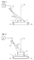
- FIG. 3 shows a cross section of a subset 7, 10 perpendicular to the assembly direction 25.
- the subset 7 is, for example, a powder compact, which has a cavity 19 inside, which is enclosed by a wall 22.
- Such hollow components are used in particular as turbine blades (three-dimensional component) which are cooled in the interior 19 and are enclosed by an outer wall 22.
- the subset 7, 10 can also be a powder compact which has no cavity 19.
- the laser beams 13 By suitable guiding of the laser beams 13, only the areas of the partial quantity 7, 10 are compressed or melted and left to solidify, which correspond to the wall 22 of the component to be produced (three-dimensional shaped body).
- the pressed powder in the middle remains undensified and loose and can be easily removed after the three-dimensional shaped body has been produced.
- Metal sheets or foils can also be used, which are given their outer and inner shape by the laser 16 and are then melted.
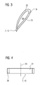
- FIG. 4 shows further subsets 7, 10.
- the subset 7, 10 is, for example, a powder compact and its composition can have a gradient or a layer structure in the direction of construction 25 or in the plane perpendicular to the direction of construction 25. The latter is the case in Figure 4.
- the subset 7, 10 consists, for example, of a material, for example a powder for a nickel or cobalt-based superalloy.
- the inner region 31 is encased by a layer 28 which has a different material composition than that of the inner region 31.
- This is, for example, a powder for an MCrAlY layer, where M stands for element from the group iron, cobalt or nickel.
- FIG. 5 shows an example of a first subset 7, a second subset 10 in which fibers 40 are arranged and a further subset 55.
- the fibers 40 can be directional or randomly jumbled. Fiber mats can also be used.
- the fibers 40 may have been pressed into powder compacts 7, 10 or may already be present in the metal sheets.
- the next layered subset 55 may, but need not, have any fibers either because, for example, no mechanical reinforcement is necessary there.
- the three-dimensional shaped body thus has a material gradient, as is also present in principle in FIG. 4.
- FIG. 6 shows a further device 1 for carrying out the method according to the invention.
- the laser 16 strikes a powder bed 52 with its laser beams 13, which represents a further consistency of the at least one starting material.
- the method is started with a certain amount of powder of a first starting material, which represents the powder bed 52 (first subset 7).
- first and / or a second material feed 46, 49 further material in the form of powder (second subset 10) is continuously or discontinuously added to the powder bed 52, so that the powder bed 52 increases in layers in the direction of construction 25.
- the composition of the supplied material can change by adding a second starting material to the first starting material in order to obtain an even distribution of a second phase (material supply for the second starting material is constant in terms of time and place, based on the powder bed 52) or by a material gradient in the subset to generate (material supply for second starting material locally, based on the powder bed 52, and possibly different in time).
- the material feeds 46, 49 can be moved locally in all directions (x, y, z).
- the first material feed 46 feeds, for example, a matrix material and the second material feed 49 can feed fibers, second phases or other components, for example.
- the laser beams 13 are used to compact only the areas of the powder bed 52 that are specified in a specified CAD model. After completion of the three-dimensional shaped body, the compressed material is removed from the loose powder filling 52. Fibers 40 or other second phases can also be present in the powder filling 52.
- first and second material feeds 46, 49 can be controlled by temporally and / or locally controlling the first and second material feeds 46, 49.
- the matrix material of the component to be manufactured is fed through the first material feed 46.
- the second material feed 49 can locally feed fibers, second phases or other constituents in different concentrations in order to generate the gradient.
- the material feeds 46, 49 can be moved in the lateral plane and in the assembly direction 25, so that a different material composition can take place in an inner and an outer area, for example by the first material feed 46 in the inner area 31 (FIG. 4) being a material feeds a superalloy and the second material feed 49 in the outer area 28 feeds, for example, the same material enriched with, for example, aluminum, chromium or MCrAlY (FIG. 4).
- a gradient in the composition can exist in the direction of construction 25 and in the plane perpendicular thereto.
- a turbine blade can have a different composition on its convex side than on the concave side. This type of gradient cannot be achieved with a casting process.
- a material gradient can be generated by changing the composition of the material over time, which is supplied via the material feeds 46, 49. If the material feed 46, 49 with respect to the three-dimensional shaped body to be produced is oriented such that the material there should have a different composition, the composition in the material feeds 46, 49 is changed at the appropriate point in time. This can be repeated from time to time.
- the explanations for the production of gradients or of second phases in the shaped body apply to the different methods described in this application (FIGS. 2, 6 and 7)
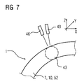
- Figure 7 shows a further device 1 to a perform the method according to the invention.
- a three-dimensional shaped body can also be produced without powder compacts 7, 10, powder fillings 52.
- the partial quantities 7, 70 are supplied in the form of powder via the first and / or second material feed 46, 49 on the starting plate 4 only to those locations where the geometry of the three-dimensional shaped body to be produced requires.
- the supplied material is connected to one another and compressed by means of electron beams or laser beams 13 with a laser focal spot 43, for example.
- the material feeds 46, 49 and the laser 16 or its laser beams 13 can be guided in three-dimensional space according to the desired geometry of the molded body.
Abstract
Description
Die Erfindung betrifft ein Verfahren zum Herstellen eines dreidimensionalen Formkörpers.The invention relates to a method for producing a three-dimensional shaped body.
Aus der DE 199 03 436 C2 ist ein Verfahren zur Herstellung dreidimensionaler Formkörper bekannt, bei dem zuerst ein Hüllkörper aufgebaut wird und anschließend mit einem zweiten Material zumindest teilweise gefüllt wird. Der Hüllkörper ist eine wesentliche Voraussetzung für das Verfahren.DE 199 03 436 C2 describes a process for the production three-dimensional shaped body known, in which a first Envelope is built up and then with a second Material is at least partially filled. The envelope is an essential requirement for the procedure.
Die EP 892 090 A1 zeigt ein Verfahren zur Reparatur eines dreidimensionalen Körpers, bei dem nur im oberflächennahen Bereich eine Schicht aufgetragen wird.EP 892 090 A1 shows a method for repairing a three-dimensional body, in which only near the surface Area a layer is applied.
Die US-PS 4,085,415, die US-PS 3,939,895, die US-PS 4,543,235
sowie die US-PS 4,036,599 zeigen Verfahren, um in gegossenen
Bauteilen Fasern einzubringen.
Zum Giessen werden Gussschalen benötigt.US Pat. No. 4,085,415, US Pat. No. 3,939,895, US Pat. No. 4,543,235 and US Pat. No. 4,036,599 show processes for introducing fibers into cast components.
Casting trays are required for casting.
Die DE 100 24 343 A1 sowie die EP 0 799 904 B1 zeigen Verfahren zur Erzeugung von Gradienten in einem metallischen oder einem keramischen Gefüge.DE 100 24 343 A1 and EP 0 799 904 B1 show Process for generating gradients in a metallic or a ceramic structure.
Es ist daher Aufgabe der Erfindung ein Verfahren aufzuzeigen, bei dem auf einfache Art und Weise ein dreidimensionaler Formkörper hergestellt werden kann.It is therefore an object of the invention to demonstrate a method in a simple way a three-dimensional Shaped body can be produced.
Die Aufgabe wird gelöst durch ein Verfahren gemäß Anspruch 1.
Dabei werden verschiedene Konsistenzen zumindest zweier
schichtförmiger Teilmengen zumindest eines Ausgangsmaterials
zu einem dreidimensionalen Formkörper verbunden. The object is achieved by a method according to
Vorteilhafte Weiterbildungen der Erfindung ergeben sich aus den Unteransprüchen.Advantageous further developments of the invention result from the subclaims.
Es zeigen
Figur 1 zeigt eine beispielhafte Vorrichtung 1, um das
erfindungsgemäße Verfahren durchzuführen.Figure 1 shows an
Innerhalb einer optional vorhandenen Heizung 34 ist bspw.
eine Startplatte 4 angeordnet, auf der eine erste
schichtförmige Teilmenge 7 aus zumindest einem ersten
Ausgangsmaterial aufliegt.
Die Teilmenge 7 kann gegenüber der Heizung 34 in einer
Aufbaurichtung 25 des dreidimensionalen Formkörpers
verschoben werden oder die Heizung 34 wird gegenüber der
Teilmenge 7 bzw. dem aufzubauenden Formkörper verschoben.A starting plate 4, for example, is arranged within an optionally
The
Aus der schichtförmigen Teilmenge 7 wird ein
dreidimensionaler Formkörper, bspw. eine Turbinenschaufel
hergestellt.
Die Teilmenge 7 ist von der Konsistenz her bspw. ein
schichtförmiger Pulverpressling, eine schichtweise
aufzubauende Pulverschüttung 52 (Fig. 6) oder ein Blech bzw.
eine Metallfolie (beide schichtförmig). A three-dimensional shaped body, for example a turbine blade, is produced from the
In terms of consistency,
Im Falle von Metallfolien oder Blechen schneidet bspw.
zumindest ein Laser 16 die gewünschte Geometrie für den
herzustellenden dreidimensionalen Formkörper heraus, wenn
diese noch nicht vorliegt.In the case of metal foils or sheets, for example,
at least one
In einem der ersten Verfahrensschritte wird die erste
schichtförmige Teilmenge 7 bspw. verdichtet. Dies ist bei
Pulverpresslingen und Pulverschüttungen notwendig, nicht
unbedingt bei Blechen oder Metallfolien.
Dies kann durch bekannte thermische Verdichtungsverfahren
(Sintern) oder mit Laserstrahlen 13 oder Elektronenstrahlen
erfolgen, die aus dem Laser 16 stammen und die Teilmenge 7
beaufschlagen (Lasersintern).
Die Laserstrahlen 13 können die erste Teilmenge 7 ganz oder
teilweise bedecken und das Material der ersten Teilmenge 7
sogar ggf. aufschmelzen.In one of the first method steps, the first layer-
This can be done by known thermal compression processes (sintering) or with
The
Der Laser 16 und/oder seine Laserstrahlen 13 können ihre
Position gegenüber der ersten Teilmenge 7 in allen
Raumrichtungen verändern. In einer Steuerungseinheit 37 ist
ein CAD Modell des dreidimensionalen Formkörpers
abgespeichert, so dass der/die Laser 16/Laserstrahlen 13 so
gesteuert werden, dass aus der ersten Teilmenge 7 und
weiteren Teilmengen 10 (Fig. 2) der gewünschte
dreidimensionale Formkörper mit seinen äußeren und inneren
Abmessungen gemäß des CAD Modells entsteht.
Der Laser 16 kann bewirken, dass die Teilmenge 7 verdichtet
wird und ggf. eine Formgebung der ersten Teilmenge 7 erfolgt.
Eine Formgebung muss bspw. nicht erfolgen, wenn der
Pulverpressling in seiner Form bereits dem entsprechenden
Teil des dreidimensionalen Formkörpers bspw. nach seiner
Schrumpfung nach der Verdichtung entspricht.
Zur Fertigstellung des Formkörpers werden so viele
schichtförmige Teilmengen 10 benötigt, wie es der Höhe des
Formkörpers in der Aufbaurichtung 25 entspricht. The
The
As many layer-
Figur 2 zeigt einen weiteren Verfahrensschritt des erfindungsgemäßen Verfahrens.Figure 2 shows a further process step of inventive method.
Auf die erste Teilmenge 7 wird eine zweite schichtförmige
Teilmenge 10 angeordnet.
Die zweite Teilmenge 10 besteht, aber nicht notwendigerweise,
bspw. aus einem zweiten Ausgangsmaterial, um bspw. einen
Materialgradienten im Formkörper zu erzeugen.
Die zweite Teilmenge 10 wird bspw. ebenfalls verdichtet,
insbesondere durch Beaufschlagung mit Laserstrahlen 13.
Der Laser 16 bewirkt ggf. auch eine Formgebung der zweiten
Teilmenge 10.
Durch die thermische Behandlung, bspw. durch die
Laserbehandlung, werden die schichtförmigen Teilmengen 7, 10
miteinander verbunden, bspw. durch Versinterung oder
Verschmelzung.A second layer-shaped
The
The
The layer-
Eine weitere Möglichkeit zur Herstellung eines
dreidimensionalen Formkörpers besteht darin, dass der aus den
zumindest zwei Teilmengen 7, 10 herzustellende
dreidimensionale Formkörper eine gerichtet erstarrte Struktur
aufweist, d.h. eine einkristalline Struktur (SX) oder nur
Korngrenzen (DS) entlang einer Richtung (Aufbaurichtung 25).
Dies kann beispielsweise dadurch erfolgen, dass bspw. die
Startplatte 4 eine gewünschte kristalline Struktur des
herzustellenden dreidimensionalen Formkörpers aufweist.
Für dieses Verfahren wird im ersten Schritt (Figur 1) die
erste Teilmenge 7 aufgeschmolzen und kontrolliert abgekühlt,
wobei die gewünschte kristalline Struktur entsteht.
In einem zweiten Schritt (Figur 2) wird die zweite Teilmenge
10 aufgelegt und aufgeschmolzen, wodurch sie sich mit der
ersten Teilmenge 7 verbindet. Ggf. wird die erste Teilmenge 7
an der Oberfläche leicht aufgeschmolzen.
Durch geeignete Führung bspw. der Heizung 34 und/oder eine
Erwärmung durch den Laser 16 wandert die Erstarrungsfront mit
der gewünschten kristallinen Struktur aus der ersten
Teilmenge 7 in der zweiten Teilmenge 10 weiter.
Dieses Verfahren kann beliebig oft wiederholt werden.
Bezüglich der Wachstumsbedingungen zum Herstellen von
kristallinen Strukturen mittels epitaktischem Wachstum ist
hier auf die EP 892 090 A1 verwiesen, die ausdrücklich
Bestandteil dieser Offenbarung sein soll.
Durch die Verwendung des Lasers 16, d.h. einer entsprechenden
Bewegung der Laserstrahlen über die Teilmengen 7, 10, werden
bspw. nur die Bereiche der Teilmengen 7, 10 verdichtet oder
aufgeschmolzen, die den Maßen des gewünschten herzustellenden
dreidimensionalen Formkörpers entsprechen. Die Teilmengen 7,
10 müssen in ihren Abmessungen also nicht dem gewünschten
dreidimensionalen Formkörper entsprechen.
Eine äußere Form oder Hülle, wie z. B. beim Gießen notwendig
ist, ist hier nicht notwendig.
Das Verbinden der schichtförmigen Teilmengen wird so oft
wiederholt bis der Formkörper entstanden ist.
Der Formkörper ist komplett nur aus einzelnen Schichten, die
beispielsweise 0,1 mm bis 1 cm dick sind, entstanden.
Insbesondere ist der Formkörper senkrecht zu einer Ebene, in
der sich die schichtförmigen Teilmengen 7, 10 erstrecken,
länger als die Ausdehnung des Formkörpers in dieser Ebene,
wie es bspw. bei einer Turbinenschaufel der Fall ist. Eine
solche Turbinenschaufel wird bspw. beginnend mit dem
Schaufelfuss Schicht für Schicht bis zur Schaufelspitze
hergestellt.Another possibility for producing a three-dimensional shaped body is that the three-dimensional shaped body to be produced from the at least two
For this method, in the first step (FIG. 1), the first
In a second step (FIG. 2), the
The solidification front with the desired crystalline structure migrates from the
This process can be repeated any number of times. With regard to the growth conditions for producing crystalline structures by means of epitaxial growth, reference is made here to EP 892 090 A1, which is expressly intended to be part of this disclosure.
By using the
An outer shape or shell, such as. B. is necessary when casting, is not necessary here.
The connection of the layered subsets is repeated until the molded body has been formed.
The molded body is created entirely from individual layers, for example 0.1 mm to 1 cm thick. In particular, the shaped body perpendicular to a plane in which the layer-shaped
Figur 3 zeigt einen Querschnitt einer Teilmenge 7, 10
senkrecht zur Aufbaurichtung 25.
Die Teilmenge 7 ist beispielsweise ein Pulverpressling, der
im Inneren einen Hohlraum 19 aufweist, der von einer Wand 22
umschlossen wird. Solche hohlen Bauteile werden insbesondere
als Turbinenschaufeln (dreidimensionales Bauteil) verwendet,
die im Inneren 19 gekühlt werden und von einer äusseren Wand
22 umschlossen sind. FIG. 3 shows a cross section of a
The
Die Teilmenge 7, 10 kann auch ein Pulverpressling sein, der
keinen Hohlraum 19 aufweist.
Durch eine geeignete Führung der Laserstrahlen 13 werden nur
die Bereiche der Teilmenge 7, 10 verdichtet oder
aufgeschmolzen und erstarren gelassen, die der Wand 22 des
herzustellenden Bauteils (dreidimensionalen Formkörper)
entsprechen. Das gepresste Pulver in der Mitte bleibt
unverdichtet und lose und kann nach der Herstellung des
dreidimensionalen Formkörpers leicht entfernt werden.
Ebenso können Metallbleche oder Folien verwendet werden, die
durch den Laser 16 ihre äußere und innere Form erhalten und
danach aufgeschmolzen werden.The
By suitable guiding of the
Metal sheets or foils can also be used, which are given their outer and inner shape by the
Figur 4 zeigt weitere Teilmengen 7, 10.
Die Teilmenge 7, 10 ist bspw. ein Pulverpressling und kann in
ihrer Zusammensetzung einen Gradienten oder einen
Schichtaufbau in Aufbaurichtung 25 oder in der Ebene
senkrecht zur Aufbaurichtung 25 aufweisen. Letzteres ist in
Figur 4 der Fall.
In einem inneren Bereich 31 besteht die Teilmenge 7, 10
beispielsweise aus einem Material, beispielsweise einem
Pulver für eine Nickel- oder Kobalt-basierte Superlegierung.
Im äußeren Bereich ist der Innenbereich 31 durch eine Schicht
28 umhüllt, die eine andere Materialzusammensetzung als die
des Innenbereichs 31 aufweist. Dies ist z.B. ein Pulver für
eine MCrAlY-Schicht, wobei M für Element der Gruppe Eisen,
Kobalt oder Nickel steht.
Bei der Beaufschlagung der Teilmengen 7, 10, 52 mit den
Laserstrahlen 13 werden ggf. deren Parameter (Intensität,
Wellenlänge, Grösse,..) dem Gradienten angepasst. FIG. 4 shows
The
In an
When the
Figur 5 zeigt beispielhaft eine erste Teilmenge 7, eine
zweite Teilmenge 10, in denen Fasern 40 angeordnet sind und
eine weitere Teilmenge 55.
Die Fasern 40 können gerichtet oder wahllos durcheinander
angeordnet sein. Ebenso können Fasermatten verwendet werden.
Die Fasern 40 können in Pulverpresslingen 7, 10 mit
eingepresst worden sein oder bereits in den Blechen vorhanden
sein.
Die nächste schichtförmige Teilmenge 55 kann, muss aber
keineswegs ebenfalls keine Fasern aufweisen, weil bspw. dort
keine mechanische Verstärkung notwendig ist. Der
dreidimensionale Formkörper weist somit einen
Materialgradienten auf, wie er im Grundsatz auch in Figur 4
vorliegt.FIG. 5 shows an example of a
The
The next
Figur 6 zeigt eine weitere Vorrichtung 1, um das
erfindungsgemässe Verfahren durchzuführen.
Der Laser 16 beaufschlagt mit seinen Laserstrahlen 13 eine
Pulverschüttung 52, die eine weitere Konsistenz des zumindest
einen Ausgangsmaterials darstellt.
Das Verfahren wird gestartet mit einer bestimmten Menge von
Pulver eines ersten Ausgangsmaterials, die die
Pulverschüttung 52 darstellt (erste Teilmenge 7).
Über eine erste und/oder auch eine zweite Materialzufuhr 46,
49 wird kontinuierlich oder diskontinuierlich der
Pulverschüttung 52 weiteres Material in Form von Pulver
(zweite Teilmenge 10) hinzugeführt, so dass die
Pulverschüttung 52 schichtweise in der Aufbaurichtung 25
zunimmt.
Die Zusammensetzung des zugeführten Materials kann sich durch
Zugabe eines zweiten Ausgangsmaterial zum ersten
Ausgangsmaterial verändern, um eine gleichmässige Verteilung
einer Zweitphase zu erhalten (Materialzufuhr für zweites
Ausgangsmaterial ist zeitlich und örtlich, bezogen auf die
Pulverschüttung 52, konstant) oder um einen
Materialgradienten in der Teilmenge zu erzeugen
(Materialzufuhr für zweites Ausgangsmaterial örtlich, bezogen
auf die Pulverschüttung 52, und ggf. zeitlich verschieden).
Die Materialzufuhren 46, 49 können in allen Richtungen
(x,y,z) örtlich bewegt werden.
Die erste Materialzuführung 46 führt bspw. ein Matrixmaterial
zu und die zweite Materialzuführung 49 kann bspw. Fasern,
Zweitphasen oder andere Bestandteile zuführen.
Mit den Laserstrahlen 13 werden nur die Bereiche der
Pulverschüttung 52 verdichtet, die in einem vorgegebenen CAD-Modell
vorgegeben sind.
Nach der Fertigstellung des dreidimensionalen Formkörpers
wird das verdichtete Material aus der losen Pulverschüttung
52 herausgenommen.
In der Pulverschüttung 52 können auch Fasern 40 oder sonstige
Zweitphasen vorhanden sein.FIG. 6 shows a
The
The method is started with a certain amount of powder of a first starting material, which represents the powder bed 52 (first subset 7).
Via a first and / or a
The composition of the supplied material can change by adding a second starting material to the first starting material in order to obtain an even distribution of a second phase (material supply for the second starting material is constant in terms of time and place, based on the powder bed 52) or by a material gradient in the subset to generate (material supply for second starting material locally, based on the
The
The
After completion of the three-dimensional shaped body, the compressed material is removed from the loose powder filling 52.
Ebenso ist es möglich, durch zeitliche und/oder örtliche
Steuerung der ersten und zweiten Materialzuführungen 46, 49,
Materialgradienten in lateraler Ebene (senkrecht zur
Aufbaurichtung 25) oder in Aufbaurichtung 25 herzustellen.
Beispielsweise wird durch die erste Materialzuführung 46 das
Matrixmaterial des herzustellenden Bauteils zugeführt.
Die zweite Materialzuführung 49 kann örtlich in verschiedener
Konzentration Fasern, Zweitphasen oder andere Bestandteile
zuführen, um den Gradienten zu erzeugen.
Die Materialzuführungen 46, 49 können in der lateralen Ebene
und in Aufbaurichtung 25 bewegt werden, so dass in einem
inneren und einem äusseren Bereich eine andere
Materialzusammensetzung erfolgen kann, indem bspw. die erste
Materialzuführung 46 im inneren Bereich 31 (Fig. 4) ein
Material einer Superlegierung zuführt und die zweite
Materialzufuhr 49 im äusseren Bereich 28 bspw. dasselbe
Material, angereichert mit bspw. Aluminium, Chrom, oder
MCrAlY zuführt (Fig. 4). It is also possible to control material gradients in the lateral plane (perpendicular to the assembly direction 25) or in the
The
The material feeds 46, 49 can be moved in the lateral plane and in the
Ein Gradient in der Zusammensetzung kann in Aufbaurichtung 25
und in der dazu senkrechten Ebene vorhanden sein.
So kann bspw. eine Turbinenschaufel auf ihrer konvexen Seite
eine andere Zusammensetzung aufweisen als auf der konkaven
Seite. Diese Art des Gradienten ist mit einem Gussverfahren
nicht zu realisieren.
Ebenso kann durch eine zeitlich veränderte Zusammensetzung
des Materials, das über die Materialzuführungen 46, 49
zugeführt wird, ein Materialgradient erzeugt werden.
Wenn die Materialzuführung 46, 49 bzgl. des herzustellenden
dreidimensionalen Formkörpers so ausgerichtet ist, dass dort
das Material eine andere Zusammensetzung aufweisen soll, so
wird die Zusammensetzung in den Materialzuführungen 46, 49 zu
dem entsprechenden Zeitpunkt geändert. Dies kann sich von
Zeit zu Zeit wiederholen.
Die Ausführungen zur Herstellung von Gradienten oder von
Zweitphasen in dem Formkörper gelten für die verschiedenen
Methoden, die in dieser Anmeldung beschrieben sind, (Fig. 2,
6, und 7)A gradient in the composition can exist in the direction of
For example, a turbine blade can have a different composition on its convex side than on the concave side. This type of gradient cannot be achieved with a casting process.
Likewise, a material gradient can be generated by changing the composition of the material over time, which is supplied via the material feeds 46, 49.
If the
The explanations for the production of gradients or of second phases in the shaped body apply to the different methods described in this application (FIGS. 2, 6 and 7)
Figur 7 zeigt eine weitere Vorrichtung 1, um ein
erfindungsgemässes Verfahren durchzuführen.Figure 7 shows a
Es kann auch ohne Pulverpresslinge 7, 10, Pulverschüttungen
52 ein dreidimensionaler Formkörper hergestellt werden.
Die Teilmengen 7, 70 werden in Form von Pulver über die erste
und/oder zweite Materialzuführung 46, 49 auf der Startplatte
4 nur den Stellen zugeführt, wo es die Geometrie des
herzustellenden dreidimensionalen Formkörpers erfordert. Das
zugeführte Material wird bspw. mittels Elektronenstrahlen
oder Laserstrahlen 13 mit einem Laserbrennfleck 43
beaufschlagt miteinander verbunden und verdichtet.
Die Materialzuführungen 46, 49 sowie der Laser 16 bzw. seine
Laserstrahlen 13 können entsprechend der gewünschten
Geometrie des Formkörpers im dreidimensionalen Raum geführt
werden.A three-dimensional shaped body can also be produced without
The
The material feeds 46, 49 and the
Claims (20)
die den kompletten Formkörper ergeben,
wobei die Teilmengen (7,10,52) des zumindest einen Ausgangsmaterials miteinander verbunden werden.Method for producing a complete three-dimensional shaped body in layers from at least two layer-shaped subsets (7, 10, 52) of at least one first starting material,
that make up the complete molded body,
wherein the subsets (7, 10, 52) of the at least one starting material are connected to one another.
dadurch gekennzeichnet, dass
eine Verdichtungsbehandlung mit zumindest einer der Teilmengen (7,10,52) durchgeführt wird.Method according to claim 1,
characterized in that
a compression treatment is carried out with at least one of the subsets (7, 10, 52).
dadurch gekennzeichnet, dass
eine thermische Verdichtungsbehandlung durchgeführt wird.Method according to claim 2,
characterized in that
thermal compression treatment is carried out.
dadurch gekennzeichnet, dass
ein Laser (16) verwendet wird,
um die Teilmengen (7,10,52) miteinander zu verbinden.Method according to claim 1,
characterized in that
a laser (16) is used
to connect the subsets (7,10,52).
dadurch gekennzeichnet, dass
ein Laser (16) zur Verdichtungsbehandlung verwendet wird. Method according to claim 2 or 3,
characterized in that
a laser (16) is used for the compaction treatment.
dadurch gekennzeichnet, dass
als Teilmenge (7,10) ein Pulverpressling oder ein Blech oder eine Metallfolie verwendet wird.Method according to claim 1,
characterized in that
a powder compact or a sheet metal or a metal foil is used as a partial quantity (7, 10).
dadurch gekennzeichnet, dass
das Ausgangsmaterial (7,10,52) aufgeschmolzen und gerichtet erstarrt wird
so dass die Verdichtung durch eine gerichtete Erstarrung mittels epitaktischem Wachstum erfolgt.Method according to claim 2,
characterized in that
the starting material (7,10,52) is melted and solidified in a directed manner
so that densification takes place by directional solidification by means of epitaxial growth.
dadurch gekennzeichnet, dass
durch die gerichtete Erstarrung ein dreidimensionaler Formkörper mit Korngrenzen gebildet wird,
wobei die Korngrenzen nur in einer Richtung (25) verlaufen.Method according to claim 7,
characterized in that
a three-dimensional shaped body with grain boundaries is formed by the directional solidification,
the grain boundaries running only in one direction (25).
dadurch gekennzeichnet, dass
durch die gerichtete Erstarrung ein einkristalliner dreidimensionaler Formkörper gebildet wird. Method according to claim 7,
characterized in that
a single-crystalline three-dimensional shaped body is formed by the directional solidification.
dadurch gekennzeichnet, dass
eine Startplatte (4) mit einer bestimmten kristallinen Struktur verwendet wird,
die die kristalline Struktur für den dreidimensionalen Formkörper vorgibt.The method of claim 7, 8 or 9,
characterized in that
a starting plate (4) with a certain crystalline structure is used,
which specifies the crystalline structure for the three-dimensional shaped body.
dadurch gekennzeichnet, dass
der dreidimensionale Formkörper so hergestellt wird,
dass er einen Materialgradienten aufweist.Method according to claim 1,
characterized in that
the three-dimensional shaped body is produced in such a way
that it has a material gradient.
dadurch gekennzeichnet, dass
zumindest eine der Teilmengen (7,10,52) einen Materialgradienten aufweist.A method according to claim 11,
characterized in that
at least one of the subsets (7, 10, 52) has a material gradient.
dadurch gekennzeichnet, dass zumindest eine Materialzuführung (46,49) benutzt wird, um Material für den Formkörper zuzuführen, und
dass der Materialgradient hergestellt wird durch zeitliche und/oder örtliche Steuerung der Materialzuführungen (46,49). A method according to claim 11,
characterized in that at least one material feed (46, 49) is used to feed material for the molded body, and
that the material gradient is created by temporal and / or local control of the material feeds (46, 49).
dadurch gekennzeichnet, dass zumindest eine Materialzuführung (46,49) für die Zuführung von Teilmengen (7,10,52) zumindest eines Ausgangsmaterials verwendet wird, und
dass während einer bestimmten Zeitdauer durch die zumindest eine Materialzuführung (46, 49) Ausgangsmaterial zugeführt wird,
wobei sich während dieser Zeitdauer die Materialzusammensetzung des Ausgangsmaterials ändert,
die durch die zumindest eine Materialzufuhr (46,49) zugeführt wird,
so dass ein Materialgradient in den Teilmengen (7,10,52) erzeugt wird.A method according to claim 11 or 13,
characterized in that at least one material feed (46, 49) is used for the feed of partial quantities (7, 10, 52) of at least one starting material, and
that starting material is supplied by the at least one material feed (46, 49) for a certain period of time,
during which the material composition of the starting material changes,
which is fed through the at least one material feed (46, 49),
so that a material gradient is created in the subsets (7,10,52).
dadurch gekennzeichnet, dass
durch zumindest zwei Materialzuführungen (46,49) Teilmengen (7,10,52) für das Ausgangsmaterial zugeführt werden,
wobei die erste Materialzuführung (46) eine erste Materialzusammensetzung zuführt und
die zweite Materialzuführung (49) ein zweite Materialzusammensetzung zuführt,
und die das beiden Materialzuführungen (46,49) jeweilige Material an verschiedenen Stellen zuführen,
so dass ein Materialgradient in den Teilmengen (7,10,52) erzeugt wird. A method according to claim 11 or 13,
characterized in that
partial quantities (7, 10, 52) for the starting material are supplied by at least two material feeds (46, 49),
wherein the first material feed (46) feeds a first material composition and
the second material feeder (49) feeds a second material composition,
and which feed the respective material feeders (46, 49) at different points,
so that a material gradient is created in the subsets (7,10,52).
dadurch gekennzeichnet, dass
die Geometrie des herzustellenden dreidimensionalen Formkörpers durch eine Bewegung der Laserstrahlen (13) des Lasers (16) über die Teilmengen (7,10,52) festgelegt wird.Method according to claim 4 or 5,
characterized in that
the geometry of the three-dimensional shaped body to be produced is determined by moving the laser beams (13) of the laser (16) over the subsets (7, 10, 52).
dadurch gekennzeichnet, dass
eine Zusatzheizung (34) verwendet wird,
um die Startplatte (4) und/oder das Ausgangsmaterial (7,10,52) aufzuheizen oder
auf einer bestimmten Temperatur zu halten.A method according to claim 1 or 10,
characterized in that
an additional heater (34) is used,
to heat the starting plate (4) and / or the starting material (7,10,52) or
to keep at a certain temperature.
dadurch gekennzeichnet, dass
der Formkörper nur aus schichtförmigen Teilmengen (7,10,52) gebildet wird.Method according to claim 1,
characterized in that
the shaped body is formed only from layer-shaped subsets (7, 10, 52).
dadurch gekennzeichnet, dass
die schichtförmigen Teilmengen (7,10) eine Dicke von 0,1 mm bis 1cm haben. Method according to claim 1,
characterized in that
the layered subsets (7, 10) have a thickness of 0.1 mm to 1 cm.
dadurch gekennzeichnet, dass
der Formkörper senkrecht zu einer Ebene,
in der sich die schichtförmigen Teilmengen (7,10) erstrecken,
länger ist als die Ausdehnung des Formkörpers in dieser Ebene.Method according to claim 1,
characterized in that
the shaped body perpendicular to a plane,
in which the layered subsets (7, 10) extend,
is longer than the extent of the shaped body in this plane.
Priority Applications (6)
| Application Number | Priority Date | Filing Date | Title |
|---|---|---|---|
| EP02020817A EP1400339A1 (en) | 2002-09-17 | 2002-09-17 | Method for manufacturing a three-dimensional object |
| US10/527,429 US7455740B2 (en) | 2002-09-17 | 2003-08-20 | Method for producing a three-dimensional moulded body |
| ES03798113T ES2266909T3 (en) | 2002-09-17 | 2003-08-20 | PROCEDURE TO PRODUCE A THREE DIMENSIONAL MOLDING BODY. |
| EP03798113A EP1539465B1 (en) | 2002-09-17 | 2003-08-20 | Method for producing a three-dimensional moulded body |
| PCT/EP2003/009236 WO2004028786A1 (en) | 2002-09-17 | 2003-08-20 | Method for producing a three-dimensional moulded body |
| DE50304075T DE50304075D1 (en) | 2002-09-17 | 2003-08-20 | METHOD FOR PRODUCING A THREE-DIMENSIONAL MOLDED BODY |
Applications Claiming Priority (1)
| Application Number | Priority Date | Filing Date | Title |
|---|---|---|---|
| EP02020817A EP1400339A1 (en) | 2002-09-17 | 2002-09-17 | Method for manufacturing a three-dimensional object |
Publications (1)
| Publication Number | Publication Date |
|---|---|
| EP1400339A1 true EP1400339A1 (en) | 2004-03-24 |
Family
ID=31896865
Family Applications (2)
| Application Number | Title | Priority Date | Filing Date |
|---|---|---|---|
| EP02020817A Withdrawn EP1400339A1 (en) | 2002-09-17 | 2002-09-17 | Method for manufacturing a three-dimensional object |
| EP03798113A Expired - Lifetime EP1539465B1 (en) | 2002-09-17 | 2003-08-20 | Method for producing a three-dimensional moulded body |
Family Applications After (1)
| Application Number | Title | Priority Date | Filing Date |
|---|---|---|---|
| EP03798113A Expired - Lifetime EP1539465B1 (en) | 2002-09-17 | 2003-08-20 | Method for producing a three-dimensional moulded body |
Country Status (5)
| Country | Link |
|---|---|
| US (1) | US7455740B2 (en) |
| EP (2) | EP1400339A1 (en) |
| DE (1) | DE50304075D1 (en) |
| ES (1) | ES2266909T3 (en) |
| WO (1) | WO2004028786A1 (en) |
Cited By (11)
| Publication number | Priority date | Publication date | Assignee | Title |
|---|---|---|---|---|
| WO2008034413A1 (en) | 2006-09-21 | 2008-03-27 | Mtu Aero Engines Gmbh | Method of repair |
| WO2008046388A1 (en) * | 2006-10-18 | 2008-04-24 | Mtu Aero Engines Gmbh | High-pressure turbine rotor, and method for the production thereof |
| WO2008046386A1 (en) * | 2006-10-18 | 2008-04-24 | Mtu Aero Engines Gmbh | Method for producing a gas turbine component |
| DE102007033715A1 (en) * | 2007-07-19 | 2009-01-22 | Siemens Ag | A method of applying a multi-material product layer to a molded article |
| DE102008056336A1 (en) * | 2008-11-07 | 2010-05-12 | Mtu Aero Engines Gmbh | repair procedures |
| WO2010057469A1 (en) * | 2008-11-22 | 2010-05-27 | Mtu Aero Engines Gmbh | Method for producing or repairing gas turbine components |
| DE102009051479A1 (en) * | 2009-10-30 | 2011-05-05 | Mtu Aero Engines Gmbh | Method and device for producing a component of a turbomachine |
| WO2013075683A1 (en) * | 2011-11-22 | 2013-05-30 | Mtu Aero Engines Gmbh | Method and device for the generative production of a component using a laser beam and corresponding turbo-engine component |
| ITCO20120058A1 (en) * | 2012-12-13 | 2014-06-14 | Nuovo Pignone Srl | METHODS FOR MANUFACTURING BLADES DIVIDED IN TURBOMACCHINE BY ADDITIVE PRODUCTION, TURBOMACCHINA POLES AND TURBOMACHINES |
| EP2815824A1 (en) * | 2013-06-21 | 2014-12-24 | Siemens Aktiengesellschaft | Method for producing a component |
| FR3046559A1 (en) * | 2016-01-12 | 2017-07-14 | Inetyx | METHOD AND INSTALLATION FOR MANUFACTURING A THREE-DIMENSIONAL OBJECT |
Families Citing this family (38)
| Publication number | Priority date | Publication date | Assignee | Title |
|---|---|---|---|---|
| US20070163114A1 (en) * | 2006-01-13 | 2007-07-19 | General Electric Company | Methods for fabricating components |
| JP4744480B2 (en) * | 2007-05-30 | 2011-08-10 | 株式会社日立製作所 | Virtual computer system |
| US8029642B2 (en) | 2007-07-27 | 2011-10-04 | The Boeing Company | Tape removal apparatus and process |
| US8345269B2 (en) | 2007-09-22 | 2013-01-01 | The Boeing Company | Method and apparatus for measuring the width of composite tape |
| US7922856B2 (en) * | 2008-01-02 | 2011-04-12 | The Boeing Company | Graphite tape supply and backing paper take-up apparatus |
| US8557074B2 (en) | 2008-02-27 | 2013-10-15 | The Boeing Company | Reduced complexity automatic fiber placement apparatus and method |
| US8986482B2 (en) | 2008-07-08 | 2015-03-24 | The Boeing Company | Method and apparatus for producing composite structures |
| EP2226149A1 (en) * | 2009-03-04 | 2010-09-08 | Siemens Aktiengesellschaft | Two-step welding method |
| US8308101B2 (en) | 2009-03-09 | 2012-11-13 | The Boeing Company | Simplified fiber tensioning for automated fiber placement machines |
| US8454788B2 (en) | 2009-03-13 | 2013-06-04 | The Boeing Company | Method and apparatus for placing short courses of composite tape |
| DE102009048665A1 (en) * | 2009-09-28 | 2011-03-31 | Siemens Aktiengesellschaft | Turbine blade and method for its production |
| DE102010011059A1 (en) | 2010-03-11 | 2011-09-15 | Global Beam Technologies Ag | Method and device for producing a component |
| DE102010034337A1 (en) * | 2010-08-14 | 2012-02-16 | Mtu Aero Engines Gmbh | Method for connecting a turbine blade with a turbine disk or a turbine ring |
| US8691333B2 (en) | 2011-06-28 | 2014-04-08 | Honeywell International Inc. | Methods for manufacturing engine components with structural bridge devices |
| DE102011080187A1 (en) * | 2011-08-01 | 2013-02-07 | Siemens Aktiengesellschaft | A method of producing a blade for a turbomachine and blade for a turbomachine |
| DE102011081112A1 (en) | 2011-08-17 | 2013-02-21 | Rolls-Royce Deutschland Ltd & Co Kg | Method for producing a component for high thermal loads, a component produced by the method and an aircraft engine with the component |
| US9266170B2 (en) | 2012-01-27 | 2016-02-23 | Honeywell International Inc. | Multi-material turbine components |
| DE102012212587A1 (en) * | 2012-07-18 | 2014-01-23 | Eos Gmbh Electro Optical Systems | Apparatus and method for layering a three-dimensional object |
| EP2696028A1 (en) * | 2012-08-06 | 2014-02-12 | Siemens Aktiengesellschaft | A turbomachine component for hot gas path of a gas turbine |
| US20140099476A1 (en) * | 2012-10-08 | 2014-04-10 | Ramesh Subramanian | Additive manufacture of turbine component with multiple materials |
| US9770781B2 (en) * | 2013-01-31 | 2017-09-26 | Siemens Energy, Inc. | Material processing through optically transmissive slag |
| US20150030871A1 (en) * | 2013-07-26 | 2015-01-29 | Gerald J. Bruck | Functionally graded thermal barrier coating system |
| EP2839905A1 (en) * | 2013-08-22 | 2015-02-25 | Astrium GmbH | Manufacturing of components from parts made from different materials, particularly of space transportation components such as combustion chambers for thrusters |
| EP2843192B1 (en) * | 2013-08-28 | 2021-03-24 | Safran Aero Boosters SA | Composite blade made by additive manufacturing and associated manufacturing process |
| JP6216881B2 (en) * | 2013-11-14 | 2017-10-18 | ゼネラル・エレクトリック・カンパニイ | Laminated production of single crystal alloy parts |
| US10288293B2 (en) | 2013-11-27 | 2019-05-14 | General Electric Company | Fuel nozzle with fluid lock and purge apparatus |
| DE102013226298A1 (en) | 2013-12-17 | 2015-06-18 | MTU Aero Engines AG | Exposure to generative production |
| WO2015094720A1 (en) * | 2013-12-20 | 2015-06-25 | United Technologies Corporation | Gradient sintered metal preform |
| US10451282B2 (en) | 2013-12-23 | 2019-10-22 | General Electric Company | Fuel nozzle structure for air assist injection |
| WO2015147935A1 (en) | 2013-12-23 | 2015-10-01 | General Electric Company | Fuel nozzle with flexible support structures |
| US9815139B2 (en) * | 2014-01-22 | 2017-11-14 | Siemens Energy, Inc. | Method for processing a part with an energy beam |
| DE102014212176A1 (en) * | 2014-06-25 | 2015-12-31 | Siemens Aktiengesellschaft | Powder bed-based additive manufacturing process and apparatus for carrying out this process |
| CN106794519B (en) * | 2014-10-14 | 2019-05-28 | 西门子能源有限公司 | The laser gain material of the three-dimensional part comprising multiple material of being formed as one system manufactures |
| US20160228995A1 (en) * | 2015-02-05 | 2016-08-11 | Siemens Energy, Inc. | Material repair process using laser and ultrasound |
| JP2017036484A (en) * | 2015-08-11 | 2017-02-16 | 株式会社日立製作所 | Metallic product production method |
| US10267718B2 (en) * | 2016-04-01 | 2019-04-23 | Caterpillar Inc. | Additive manufactured component that indicates wear and system and method thereof |
| DE102017130126A1 (en) | 2017-12-15 | 2019-06-19 | Deutsches Zentrum für Luft- und Raumfahrt e.V. | Gyroscope carrier structure, inertial spacecraft measurement unit and spacecraft |
| CN109277699A (en) * | 2018-09-28 | 2019-01-29 | 浙江浙能技术研究院有限公司 | A kind of increasing material manufacturing method of heterogenous steel pipe connector |
Citations (3)
| Publication number | Priority date | Publication date | Assignee | Title |
|---|---|---|---|---|
| WO1992010343A1 (en) * | 1990-12-07 | 1992-06-25 | Board Of Regents, The University Of Texas System | Producing parts by compound formation of precursor powders |
| WO2001045882A2 (en) * | 1999-11-16 | 2001-06-28 | Triton Systems, Inc. | Laser fabrication of discontinuously reinforced metal matrix composites |
| US6355086B2 (en) * | 1997-08-12 | 2002-03-12 | Rolls-Royce Corporation | Method and apparatus for making components by direct laser processing |
Family Cites Families (10)
| Publication number | Priority date | Publication date | Assignee | Title |
|---|---|---|---|---|
| US4036599A (en) | 1973-07-12 | 1977-07-19 | E. I. Du Pont De Nemours And Company | Polycrystalline alumina fibers as reinforcement in magnesium matrix |
| US3939895A (en) | 1974-11-18 | 1976-02-24 | General Electric Company | Method for casting directionally solidified articles |
| US4085415A (en) | 1976-05-06 | 1978-04-18 | Fuji Photo Film Co., Ltd. | Photographic processing apparatus |
| US4543235A (en) | 1982-09-22 | 1985-09-24 | United Technologies Corporation | Eutectic superalloy compositions and articles |
| US6350326B1 (en) * | 1996-01-15 | 2002-02-26 | The University Of Tennessee Research Corporation | Method for practicing a feedback controlled laser induced surface modification |
| CN1074689C (en) | 1996-04-04 | 2001-11-14 | E·O·帕通电子焊接研究院电子束工艺国际中心 | Method of producing on substrate of protective coatings with chemical composition and structure gradient across thickness and with top ceramic layer |
| EP0892090B1 (en) | 1997-02-24 | 2008-04-23 | Sulzer Innotec Ag | Method for manufacturing single crystal structures |
| EP0861927A1 (en) * | 1997-02-24 | 1998-09-02 | Sulzer Innotec Ag | Method for manufacturing single crystal structures |
| DE19903436C2 (en) | 1999-01-29 | 2001-02-08 | Fraunhofer Ges Forschung | Process for the production of three-dimensional shaped bodies |
| DE10024343A1 (en) | 2000-05-17 | 2001-11-22 | Gfe Met & Mat Gmbh | One-piece component used e.g. for valves in combustion engines has a lamella cast structure |
-
2002
- 2002-09-17 EP EP02020817A patent/EP1400339A1/en not_active Withdrawn
-
2003
- 2003-08-20 EP EP03798113A patent/EP1539465B1/en not_active Expired - Lifetime
- 2003-08-20 US US10/527,429 patent/US7455740B2/en active Active
- 2003-08-20 WO PCT/EP2003/009236 patent/WO2004028786A1/en not_active Application Discontinuation
- 2003-08-20 DE DE50304075T patent/DE50304075D1/en not_active Expired - Lifetime
- 2003-08-20 ES ES03798113T patent/ES2266909T3/en not_active Expired - Lifetime
Patent Citations (3)
| Publication number | Priority date | Publication date | Assignee | Title |
|---|---|---|---|---|
| WO1992010343A1 (en) * | 1990-12-07 | 1992-06-25 | Board Of Regents, The University Of Texas System | Producing parts by compound formation of precursor powders |
| US6355086B2 (en) * | 1997-08-12 | 2002-03-12 | Rolls-Royce Corporation | Method and apparatus for making components by direct laser processing |
| WO2001045882A2 (en) * | 1999-11-16 | 2001-06-28 | Triton Systems, Inc. | Laser fabrication of discontinuously reinforced metal matrix composites |
Cited By (23)
| Publication number | Priority date | Publication date | Assignee | Title |
|---|---|---|---|---|
| WO2008034413A1 (en) | 2006-09-21 | 2008-03-27 | Mtu Aero Engines Gmbh | Method of repair |
| WO2008046388A1 (en) * | 2006-10-18 | 2008-04-24 | Mtu Aero Engines Gmbh | High-pressure turbine rotor, and method for the production thereof |
| WO2008046386A1 (en) * | 2006-10-18 | 2008-04-24 | Mtu Aero Engines Gmbh | Method for producing a gas turbine component |
| EP2218530A1 (en) * | 2006-10-18 | 2010-08-18 | MTU Aero Engines AG | High Pressure Turbine Rotor and Process for its Manufacture |
| DE102007033715A1 (en) * | 2007-07-19 | 2009-01-22 | Siemens Ag | A method of applying a multi-material product layer to a molded article |
| DE102008056336A1 (en) * | 2008-11-07 | 2010-05-12 | Mtu Aero Engines Gmbh | repair procedures |
| US8708682B2 (en) | 2008-11-07 | 2014-04-29 | Mtu Aero Engines Gmbh | Repair method |
| WO2010057469A1 (en) * | 2008-11-22 | 2010-05-27 | Mtu Aero Engines Gmbh | Method for producing or repairing gas turbine components |
| DE102009051479A1 (en) * | 2009-10-30 | 2011-05-05 | Mtu Aero Engines Gmbh | Method and device for producing a component of a turbomachine |
| US10144062B2 (en) | 2009-10-30 | 2018-12-04 | Mtu Aero Engines Gmbh | Method and device for producing a component of a turbomachine |
| EP2782705B1 (en) | 2011-11-22 | 2017-09-13 | MTU Aero Engines GmbH | Method of generative producing a component using a laser beam before, during and after the assembly |
| WO2013075683A1 (en) * | 2011-11-22 | 2013-05-30 | Mtu Aero Engines Gmbh | Method and device for the generative production of a component using a laser beam and corresponding turbo-engine component |
| US10830068B2 (en) | 2011-11-22 | 2020-11-10 | MTU Aero Engines AG | Method and device for the generative production of a component using a laser beam and corresponding turbo-engine component |
| EP2743452A1 (en) * | 2012-12-13 | 2014-06-18 | Nuovo Pignone S.p.A. | Methods of manufacturing divided blades of turbomachines by additive manufacturing |
| ITCO20120058A1 (en) * | 2012-12-13 | 2014-06-14 | Nuovo Pignone Srl | METHODS FOR MANUFACTURING BLADES DIVIDED IN TURBOMACCHINE BY ADDITIVE PRODUCTION, TURBOMACCHINA POLES AND TURBOMACHINES |
| EP2815824A1 (en) * | 2013-06-21 | 2014-12-24 | Siemens Aktiengesellschaft | Method for producing a component |
| FR3046559A1 (en) * | 2016-01-12 | 2017-07-14 | Inetyx | METHOD AND INSTALLATION FOR MANUFACTURING A THREE-DIMENSIONAL OBJECT |
| WO2017121746A1 (en) | 2016-01-12 | 2017-07-20 | Inetyx | Method and facility for manufacturing a three-dimensional object |
| KR20180103893A (en) * | 2016-01-12 | 2018-09-19 | 이네티스 | Method and apparatus for manufacturing a three-dimensional object |
| CN108698170A (en) * | 2016-01-12 | 2018-10-23 | 依耐提科斯公司 | Method and apparatus for manufacturing three-dimension object |
| CN108698170B (en) * | 2016-01-12 | 2020-07-28 | 依耐提科斯公司 | Method and apparatus for manufacturing three-dimensional objects |
| US10850351B2 (en) | 2016-01-12 | 2020-12-01 | Inetyx | Method and facility for manufacturing a three-dimensional object |
| KR102643378B1 (en) * | 2016-01-12 | 2024-03-04 | 이네티스 | Method and equipment for manufacturing three-dimensional objects |
Also Published As
| Publication number | Publication date |
|---|---|
| US20050268998A1 (en) | 2005-12-08 |
| WO2004028786A1 (en) | 2004-04-08 |
| ES2266909T3 (en) | 2007-03-01 |
| US7455740B2 (en) | 2008-11-25 |
| DE50304075D1 (en) | 2006-08-10 |
| EP1539465B1 (en) | 2006-06-28 |
| EP1539465A1 (en) | 2005-06-15 |
Similar Documents
| Publication | Publication Date | Title |
|---|---|---|
| EP1539465B1 (en) | Method for producing a three-dimensional moulded body | |
| DE102008031925B4 (en) | Dual manufacturing process for small series products | |
| EP3099469B1 (en) | Method and device for the improved control of the energy input in a generative layer construction method | |
| EP2785481B1 (en) | Process for producing a shaped body by layerwise buildup from material powder | |
| EP1720676B1 (en) | Method and device used to produce a set of control data for producing products by free-form sintering and/or melting, in addition to a device for the production thereof | |
| EP1568472B1 (en) | Method and device for producing parts by sintering and/or melting | |
| DE10344902B4 (en) | Method for producing a three-dimensional object | |
| EP3017895A1 (en) | Manufacture of a component through selective laser melting | |
| WO2002042056A1 (en) | Generative method for producing a part and device for carrying out this method | |
| DE102011005929A1 (en) | Device and method for producing a component in layered construction | |
| DE102010029078A1 (en) | Producing an article by layer-wise structures made of powdered metallic or ceramic material, comprises individually preparing material powder layers subsequent to each other on a support, and location-selectively solidifying each layer | |
| WO2009024258A1 (en) | Method for the production of a building component and use of the building component produced according to the method | |
| DE102018202506A1 (en) | Controlled solidification additive manufacturing process and associated apparatus | |
| EP3077180A1 (en) | Process for the accelerated production of objects by means of generative manufacturing | |
| DE102007057450A1 (en) | Producing three-dimensional articles e.g. injection mold, comprises applying and pressing solidifyable fluid or powdered material layer on target surface, and illuminating selected part of the layer with energy beam or material beam | |
| WO2019011641A1 (en) | Method for a component with a predetermined surface structure to be produced by additive manufacturing | |
| DE102016225178A1 (en) | Layer construction device and layer construction method for the additive production of at least one component region of a component | |
| WO2018206581A1 (en) | Position-specific input of energy | |
| EP0681521B1 (en) | Process and device for producing three-dimensional objects | |
| DE10065594C2 (en) | Process for the production of 3-dimensional sintered workpieces | |
| EP3718729B1 (en) | Production method with additive component manufacture and finishing | |
| EP3416813B1 (en) | Processing tool and method for production thereof by means of a generative layer construction process | |
| DE102018209239A1 (en) | Production method for a forming tool part of a press-hardening tool | |
| DE102006044044A1 (en) | Method and device for producing a three-dimensional article from a solidifiable material | |
| DE102018206147A1 (en) | Additive manufacturing process |
Legal Events
| Date | Code | Title | Description |
|---|---|---|---|
| PUAI | Public reference made under article 153(3) epc to a published international application that has entered the european phase |
Free format text: ORIGINAL CODE: 0009012 |
|
| AK | Designated contracting states |
Kind code of ref document: A1 Designated state(s): AT BE BG CH CY CZ DE DK EE ES FI FR GB GR IE IT LI LU MC NL PT SE SK TR |
|
| AX | Request for extension of the european patent |
Extension state: AL LT LV MK RO SI |
|
| AKX | Designation fees paid | ||
| REG | Reference to a national code |
Ref country code: DE Ref legal event code: 8566 |
|
| STAA | Information on the status of an ep patent application or granted ep patent |
Free format text: STATUS: THE APPLICATION IS DEEMED TO BE WITHDRAWN |
|
| 18D | Application deemed to be withdrawn |
Effective date: 20040925 |